EP4414764A1 - General traffic headlight - Google Patents
General traffic headlight Download PDFInfo
- Publication number
- EP4414764A1 EP4414764A1 EP23166252.9A EP23166252A EP4414764A1 EP 4414764 A1 EP4414764 A1 EP 4414764A1 EP 23166252 A EP23166252 A EP 23166252A EP 4414764 A1 EP4414764 A1 EP 4414764A1
- Authority
- EP
- European Patent Office
- Prior art keywords
- free
- form surface
- light
- collimator
- baffle
- Prior art date
- Legal status (The legal status is an assumption and is not a legal conclusion. Google has not performed a legal analysis and makes no representation as to the accuracy of the status listed.)
- Pending
Links
Images


Classifications
-
- G—PHYSICS
- G02—OPTICS
- G02B—OPTICAL ELEMENTS, SYSTEMS OR APPARATUS
- G02B19/00—Condensers, e.g. light collectors or similar non-imaging optics
- G02B19/0033—Condensers, e.g. light collectors or similar non-imaging optics characterised by the use
- G02B19/0047—Condensers, e.g. light collectors or similar non-imaging optics characterised by the use for use with a light source
- G02B19/0061—Condensers, e.g. light collectors or similar non-imaging optics characterised by the use for use with a light source the light source comprising a LED
-
- B—PERFORMING OPERATIONS; TRANSPORTING
- B60—VEHICLES IN GENERAL
- B60Q—ARRANGEMENT OF SIGNALLING OR LIGHTING DEVICES, THE MOUNTING OR SUPPORTING THEREOF OR CIRCUITS THEREFOR, FOR VEHICLES IN GENERAL
- B60Q1/00—Arrangement of optical signalling or lighting devices, the mounting or supporting thereof or circuits therefor
- B60Q1/02—Arrangement of optical signalling or lighting devices, the mounting or supporting thereof or circuits therefor the devices being primarily intended to illuminate the way ahead or to illuminate other areas of way or environments
- B60Q1/04—Arrangement of optical signalling or lighting devices, the mounting or supporting thereof or circuits therefor the devices being primarily intended to illuminate the way ahead or to illuminate other areas of way or environments the devices being headlights
-
- B—PERFORMING OPERATIONS; TRANSPORTING
- B62—LAND VEHICLES FOR TRAVELLING OTHERWISE THAN ON RAILS
- B62J—CYCLE SADDLES OR SEATS; AUXILIARY DEVICES OR ACCESSORIES SPECIALLY ADAPTED TO CYCLES AND NOT OTHERWISE PROVIDED FOR, e.g. ARTICLE CARRIERS OR CYCLE PROTECTORS
- B62J6/00—Arrangement of optical signalling or lighting devices on cycles; Mounting or supporting thereof; Circuits therefor
- B62J6/02—Headlights
- B62J6/022—Headlights specially adapted for motorcycles or the like
- B62J6/026—Headlights specially adapted for motorcycles or the like characterised by the structure, e.g. casings
-
- F—MECHANICAL ENGINEERING; LIGHTING; HEATING; WEAPONS; BLASTING
- F21—LIGHTING
- F21S—NON-PORTABLE LIGHTING DEVICES; SYSTEMS THEREOF; VEHICLE LIGHTING DEVICES SPECIALLY ADAPTED FOR VEHICLE EXTERIORS
- F21S41/00—Illuminating devices specially adapted for vehicle exteriors, e.g. headlamps
- F21S41/10—Illuminating devices specially adapted for vehicle exteriors, e.g. headlamps characterised by the light source
- F21S41/14—Illuminating devices specially adapted for vehicle exteriors, e.g. headlamps characterised by the light source characterised by the type of light source
- F21S41/141—Light emitting diodes [LED]
- F21S41/143—Light emitting diodes [LED] the main emission direction of the LED being parallel to the optical axis of the illuminating device
-
- F—MECHANICAL ENGINEERING; LIGHTING; HEATING; WEAPONS; BLASTING
- F21—LIGHTING
- F21S—NON-PORTABLE LIGHTING DEVICES; SYSTEMS THEREOF; VEHICLE LIGHTING DEVICES SPECIALLY ADAPTED FOR VEHICLE EXTERIORS
- F21S41/00—Illuminating devices specially adapted for vehicle exteriors, e.g. headlamps
- F21S41/10—Illuminating devices specially adapted for vehicle exteriors, e.g. headlamps characterised by the light source
- F21S41/14—Illuminating devices specially adapted for vehicle exteriors, e.g. headlamps characterised by the light source characterised by the type of light source
- F21S41/141—Light emitting diodes [LED]
- F21S41/151—Light emitting diodes [LED] arranged in one or more lines
-
- F—MECHANICAL ENGINEERING; LIGHTING; HEATING; WEAPONS; BLASTING
- F21—LIGHTING
- F21S—NON-PORTABLE LIGHTING DEVICES; SYSTEMS THEREOF; VEHICLE LIGHTING DEVICES SPECIALLY ADAPTED FOR VEHICLE EXTERIORS
- F21S41/00—Illuminating devices specially adapted for vehicle exteriors, e.g. headlamps
- F21S41/20—Illuminating devices specially adapted for vehicle exteriors, e.g. headlamps characterised by refractors, transparent cover plates, light guides or filters
- F21S41/25—Projection lenses
- F21S41/255—Lenses with a front view of circular or truncated circular outline
-
- F—MECHANICAL ENGINEERING; LIGHTING; HEATING; WEAPONS; BLASTING
- F21—LIGHTING
- F21S—NON-PORTABLE LIGHTING DEVICES; SYSTEMS THEREOF; VEHICLE LIGHTING DEVICES SPECIALLY ADAPTED FOR VEHICLE EXTERIORS
- F21S41/00—Illuminating devices specially adapted for vehicle exteriors, e.g. headlamps
- F21S41/20—Illuminating devices specially adapted for vehicle exteriors, e.g. headlamps characterised by refractors, transparent cover plates, light guides or filters
- F21S41/285—Refractors, transparent cover plates, light guides or filters not provided in groups F21S41/24 - F21S41/2805
-
- F—MECHANICAL ENGINEERING; LIGHTING; HEATING; WEAPONS; BLASTING
- F21—LIGHTING
- F21S—NON-PORTABLE LIGHTING DEVICES; SYSTEMS THEREOF; VEHICLE LIGHTING DEVICES SPECIALLY ADAPTED FOR VEHICLE EXTERIORS
- F21S41/00—Illuminating devices specially adapted for vehicle exteriors, e.g. headlamps
- F21S41/30—Illuminating devices specially adapted for vehicle exteriors, e.g. headlamps characterised by reflectors
- F21S41/32—Optical layout thereof
- F21S41/322—Optical layout thereof the reflector using total internal reflection
-
- F—MECHANICAL ENGINEERING; LIGHTING; HEATING; WEAPONS; BLASTING
- F21—LIGHTING
- F21S—NON-PORTABLE LIGHTING DEVICES; SYSTEMS THEREOF; VEHICLE LIGHTING DEVICES SPECIALLY ADAPTED FOR VEHICLE EXTERIORS
- F21S41/00—Illuminating devices specially adapted for vehicle exteriors, e.g. headlamps
- F21S41/40—Illuminating devices specially adapted for vehicle exteriors, e.g. headlamps characterised by screens, non-reflecting members, light-shielding members or fixed shades
- F21S41/43—Illuminating devices specially adapted for vehicle exteriors, e.g. headlamps characterised by screens, non-reflecting members, light-shielding members or fixed shades characterised by the shape thereof
-
- F—MECHANICAL ENGINEERING; LIGHTING; HEATING; WEAPONS; BLASTING
- F21—LIGHTING
- F21S—NON-PORTABLE LIGHTING DEVICES; SYSTEMS THEREOF; VEHICLE LIGHTING DEVICES SPECIALLY ADAPTED FOR VEHICLE EXTERIORS
- F21S8/00—Lighting devices intended for fixed installation
-
- F—MECHANICAL ENGINEERING; LIGHTING; HEATING; WEAPONS; BLASTING
- F21—LIGHTING
- F21V—FUNCTIONAL FEATURES OR DETAILS OF LIGHTING DEVICES OR SYSTEMS THEREOF; STRUCTURAL COMBINATIONS OF LIGHTING DEVICES WITH OTHER ARTICLES, NOT OTHERWISE PROVIDED FOR
- F21V1/00—Shades for light sources, i.e. lampshades for table, floor, wall or ceiling lamps
-
- F—MECHANICAL ENGINEERING; LIGHTING; HEATING; WEAPONS; BLASTING
- F21—LIGHTING
- F21V—FUNCTIONAL FEATURES OR DETAILS OF LIGHTING DEVICES OR SYSTEMS THEREOF; STRUCTURAL COMBINATIONS OF LIGHTING DEVICES WITH OTHER ARTICLES, NOT OTHERWISE PROVIDED FOR
- F21V11/00—Screens not covered by groups F21V1/00, F21V3/00, F21V7/00 or F21V9/00
-
- F—MECHANICAL ENGINEERING; LIGHTING; HEATING; WEAPONS; BLASTING
- F21—LIGHTING
- F21V—FUNCTIONAL FEATURES OR DETAILS OF LIGHTING DEVICES OR SYSTEMS THEREOF; STRUCTURAL COMBINATIONS OF LIGHTING DEVICES WITH OTHER ARTICLES, NOT OTHERWISE PROVIDED FOR
- F21V5/00—Refractors for light sources
- F21V5/04—Refractors for light sources of lens shape
-
- F—MECHANICAL ENGINEERING; LIGHTING; HEATING; WEAPONS; BLASTING
- F21—LIGHTING
- F21V—FUNCTIONAL FEATURES OR DETAILS OF LIGHTING DEVICES OR SYSTEMS THEREOF; STRUCTURAL COMBINATIONS OF LIGHTING DEVICES WITH OTHER ARTICLES, NOT OTHERWISE PROVIDED FOR
- F21V7/00—Reflectors for light sources
- F21V7/0091—Reflectors for light sources using total internal reflection
-
- F—MECHANICAL ENGINEERING; LIGHTING; HEATING; WEAPONS; BLASTING
- F21—LIGHTING
- F21V—FUNCTIONAL FEATURES OR DETAILS OF LIGHTING DEVICES OR SYSTEMS THEREOF; STRUCTURAL COMBINATIONS OF LIGHTING DEVICES WITH OTHER ARTICLES, NOT OTHERWISE PROVIDED FOR
- F21V7/00—Reflectors for light sources
- F21V7/04—Optical design
-
- G—PHYSICS
- G02—OPTICS
- G02B—OPTICAL ELEMENTS, SYSTEMS OR APPARATUS
- G02B19/00—Condensers, e.g. light collectors or similar non-imaging optics
-
- G—PHYSICS
- G02—OPTICS
- G02B—OPTICAL ELEMENTS, SYSTEMS OR APPARATUS
- G02B19/00—Condensers, e.g. light collectors or similar non-imaging optics
- G02B19/0004—Condensers, e.g. light collectors or similar non-imaging optics characterised by the optical means employed
- G02B19/0028—Condensers, e.g. light collectors or similar non-imaging optics characterised by the optical means employed refractive and reflective surfaces, e.g. non-imaging catadioptric systems
-
- G—PHYSICS
- G02—OPTICS
- G02B—OPTICAL ELEMENTS, SYSTEMS OR APPARATUS
- G02B27/00—Optical systems or apparatus not provided for by any of the groups G02B1/00 - G02B26/00, G02B30/00
- G02B27/0012—Optical design, e.g. procedures, algorithms, optimisation routines
-
- G—PHYSICS
- G02—OPTICS
- G02B—OPTICAL ELEMENTS, SYSTEMS OR APPARATUS
- G02B27/00—Optical systems or apparatus not provided for by any of the groups G02B1/00 - G02B26/00, G02B30/00
- G02B27/09—Beam shaping, e.g. changing the cross-sectional area, not otherwise provided for
- G02B27/0916—Adapting the beam shape of a semiconductor light source such as a laser diode or an LED, e.g. for efficiently coupling into optical fibers
-
- G—PHYSICS
- G02—OPTICS
- G02B—OPTICAL ELEMENTS, SYSTEMS OR APPARATUS
- G02B27/00—Optical systems or apparatus not provided for by any of the groups G02B1/00 - G02B26/00, G02B30/00
- G02B27/30—Collimators
-
- G—PHYSICS
- G02—OPTICS
- G02B—OPTICAL ELEMENTS, SYSTEMS OR APPARATUS
- G02B3/00—Simple or compound lenses
-
- F—MECHANICAL ENGINEERING; LIGHTING; HEATING; WEAPONS; BLASTING
- F21—LIGHTING
- F21W—INDEXING SCHEME ASSOCIATED WITH SUBCLASSES F21K, F21L, F21S and F21V, RELATING TO USES OR APPLICATIONS OF LIGHTING DEVICES OR SYSTEMS
- F21W2102/00—Exterior vehicle lighting devices for illuminating purposes
-
- F—MECHANICAL ENGINEERING; LIGHTING; HEATING; WEAPONS; BLASTING
- F21—LIGHTING
- F21W—INDEXING SCHEME ASSOCIATED WITH SUBCLASSES F21K, F21L, F21S and F21V, RELATING TO USES OR APPLICATIONS OF LIGHTING DEVICES OR SYSTEMS
- F21W2107/00—Use or application of lighting devices on or in particular types of vehicles
- F21W2107/10—Use or application of lighting devices on or in particular types of vehicles for land vehicles
-
- F—MECHANICAL ENGINEERING; LIGHTING; HEATING; WEAPONS; BLASTING
- F21—LIGHTING
- F21Y—INDEXING SCHEME ASSOCIATED WITH SUBCLASSES F21K, F21L, F21S and F21V, RELATING TO THE FORM OR THE KIND OF THE LIGHT SOURCES OR OF THE COLOUR OF THE LIGHT EMITTED
- F21Y2115/00—Light-generating elements of semiconductor light sources
- F21Y2115/10—Light-emitting diodes [LED]
-
- G—PHYSICS
- G02—OPTICS
- G02B—OPTICAL ELEMENTS, SYSTEMS OR APPARATUS
- G02B19/00—Condensers, e.g. light collectors or similar non-imaging optics
- G02B19/0004—Condensers, e.g. light collectors or similar non-imaging optics characterised by the optical means employed
- G02B19/0009—Condensers, e.g. light collectors or similar non-imaging optics characterised by the optical means employed having refractive surfaces only
- G02B19/0014—Condensers, e.g. light collectors or similar non-imaging optics characterised by the optical means employed having refractive surfaces only at least one surface having optical power
-
- G—PHYSICS
- G02—OPTICS
- G02B—OPTICAL ELEMENTS, SYSTEMS OR APPARATUS
- G02B3/00—Simple or compound lenses
- G02B3/02—Simple or compound lenses with non-spherical faces
- G02B3/04—Simple or compound lenses with non-spherical faces with continuous faces that are rotationally symmetrical but deviate from a true sphere, e.g. so called "aspheric" lenses
-
- G—PHYSICS
- G06—COMPUTING OR CALCULATING; COUNTING
- G06N—COMPUTING ARRANGEMENTS BASED ON SPECIFIC COMPUTATIONAL MODELS
- G06N3/00—Computing arrangements based on biological models
- G06N3/004—Artificial life, i.e. computing arrangements simulating life
- G06N3/006—Artificial life, i.e. computing arrangements simulating life based on simulated virtual individual or collective life forms, e.g. social simulations or particle swarm optimisation [PSO]
Definitions
- the present invention relates to a lighting technology, in particular to a headlight for a vehicle.
- LED vehicle lights have the advantages of being long in illumination distance, low in power requirements and high in brightness.
- the motorcycle lights and the electric headlights comply with the relevant regulatory requirements, it is necessary to carry out adaptive design on LED vehicle lights with different wheels.
- the technical problem to be solved by the present invention is how to simplify the adaptive design of LED vehicle lights, so that the LED vehicle lights are allowed to meet the needs of a variety of traffic lighting, and accord with the relevant regulatory requirements.
- a general traffic headlight includes LEDs, a free-form surface convergence system located in front of the LEDs, a baffle located in front of the free-form surface convergence system, and a free-form surface outer lens located in front of the baffle, where the free-form surface convergence system includes a collimator and a free-form surface; and all light rays are shot into the distance in parallel along an optical axis by the collimator, and the free-form surface at a light-emitting window is employed to design a light shape that meets the regulatory requirements.
- a structure of the headlight in this design is mainly composed of the collimator, the free-form surface, and the free-form surface outer lens. All the light rays are shot into the distance in parallel along the optical axis by the collimator, and the free-form surface at the light-emitting window is employed to design the light shape that meets the regulatory requirements.
- the LEDs are adopted as light sources. The light emitted by the LEDs forms parallel light through the collimator, and is then scattered and deflected via the free-form surface outer lens so as to meet the relevant regulatory requirements and regulations, thus achieving the effects of illuminating the road surface and preventing glare at the same time.
- the entire free-form surface light convergence system in this design is designed and optimized by employing the free-form surface.
- the system is divided into two parts, i.e., a total reflection portion and a refraction portion.
- the system can control the distribution of light. Light control is performed by analyzing the regulatory requirements for different vehicles, so that the overall volume can be made smaller.
- the free-form surface is used for design, so that the light-gathering efficiency of the whole light convergence system will be higher, and the volume thereof will be smaller.
- the free-form surface light convergence system can be better than the conventional light convergence system.
- the free-form surface light convergence system is designed by combining direct calculation with an optimization algorithm.
- a light source is approximated to a point light source, the surface of the light convergence system is approximated to a plane, and a mesh mapping method and an iterative algorithm are used to solve refracting and total reflecting surfaces, so that an initial surface shape of the light convergence system is obtained.
- an optical model is established according to the structure of a vehicle light, the light source is set as a surface light source, the refracting and total reflecting surfaces of the light convergence system are optimized at the same time, and a surface shape of the light convergence system is finally obtained.
- the vehicle light can be made more versatile and smaller in size, realizes the versatility of different vehicle lighting, and has the characteristics of being long in lighting distance, high in lighting intensity, low in energy consumption, and the like.
- the baffle in this design is not a single baffle.
- the baffle includes a combination of baffles for various traffic vehicles, such as a baffle with a 45-degree angle or a 15-degree angle for a car; when being used for a motorcycle, the baffle will be replaced with a flat baffle without an angle; the flat baffle is also used for lighting an electric vehicle; and the flat baffle can also be used for lighting a bicycle.
- the power of a chip and the corresponding particle number will be adjusted accordingly, but there is no need to redesign an inner lens.
- the lighting needs of the different vehicles such as electric vehicles, motorcycles and automobiles, can be met.
- the free-form surface convergence system is designed, the lighting changes caused by the different particle numbers and power have been taken into account, which can be used to meet different vehicle lighting requirements.
- a brand new design of a general LED traffic headlight with light distribution for a car, a motorcycle, or the like includes LEDs, a free-form surface convergence system 40, a different type of baffle 30, and a free-form surface outer lens 10.
- the LEDs are installed on an LED particle board 50, the LED particle board is installed on a radiator 60, the radiator is provided with a decorative frame 20, and the free-form surface outer lens 10, the baffle 30, and the free-form surface convergence system 40 are located in the decorative frame 20.
- the baffle 30 is installed on a baffle bearing frame 31, and the baffle bearing frame is installed on the radiator 60.
- the core of the free-form surface convergence system 40 is to divide an light incident end of a condenser into different areas in a circumferential direction to carry out separate design in the different areas, thus meeting the lighting requirements of different traffic vehicles at the same time, or meeting the needs of special vehicles for the special lighting effects at different positions in the circumferential direction of the condenser.
- the free-form surface convergence system 40 divides a small-angle incident light receiving surface into multiple refracting surfaces, so that the refracting surfaces have at least two focal length specifications.
- the orthogonal projections of the refracting surfaces along the direction of a designed optical axis are sectors with the same center, and the sum of central angles of all the sectors is 360 degrees.
- a step structure is formed at a junction of every two adjacent refracting surfaces, and a plane passing through the designed optical axis is used as an interface.
- This method is equivalent to performing circumferential sector partition on the small-angle incident light receiving surface at the light incident end with the designed optical axis as a center, which can make the different areas in the circumferential direction of the condenser have different light collection efficiencies, light utilization rates and lighting effects. Furthermore, the structure is relatively simple, and the light distribution can be quickly controlled, so that the lighting requirements of the different vehicles are met.
- the total reflecting surface at the light incident end is further divided into a plurality of total reflection blocks.
- All the total reflection blocks are segments of rotating surfaces whose rotation axes coincide with the designed optical axis, but there are at least two different plane curves that form the total reflection blocks.
- the orthographic projections of all the total reflection blocks along the direction of the designed optical axis are sector rings with the same center, and the sum of central angles corresponding to all the sector rings is 360 degrees.
- a step structure is formed at a junction of every two adjacent total reflection blocks, and a plane passing through the designed optical axis is used as an interface.
- the total reflection blocks and the refracting surfaces are in one-to-one correspondence in a radial direction, and the central angles corresponding to the total reflection blocks coincide with the central angles corresponding to the refracting surfaces.
- the light distribution is projected by means of the free-form surface outer lens 10. After corresponding calculation, different regulatory requirements and illumination requirements can be met.
- the vehicle lights of the different vehicles are different in traffic lighting requirements and regulatory requirements.
- the main method is to control the free-form surface convergence system 40, the change of the baffle 30 and the number of LED particles.
- the free-form surface convergence system 40 includes a collimator and a free-form surface.
- a collimation optimizing lens method is first designed.
- the optical design of the LED collimator for the vehicle light is based on extended LED light sources. Based on LED point light sources, the LED collimator for the vehicle light is designed as an initial structure. A surface light source is discretized into the several point light sources, and a contour for the LED collimator for the vehicle light is designed for each of the point light sources. The contours for the collimator are respectively multiplied by weight coefficients, the weighted contours are superimposed, and then the superimposed contour is optimized, and the optimized variables are the weight coefficients.
- a particle swarm optimization algorithm is used to find the best weight ratio, so that the system efficiency is improved.
- the simulation verification shows that the efficiency can be increased by 20% to 30%.
- the working principle of the optimized collimator is total reflection. In a process of light transmission, part of the light is transmitted by light using the principle of total reflection. Because the collimator is rotationally axisymmetric, only an upper half part of the collimator is analyzed. As shown in FIG. 5 , a split line MN divides the light emitted from a point O into two parts. When the light is refracted to the interior through a part ac of an inner wall of an inner hole, the light that reaches an outer contour curve ab of the collimator will be completely reflected by an internal structure of the collimator, and is thus emitted in parallel.
- the refraction from a center cd of the inner hole to the interior mainly uses an aspheric lens to make the light emitted in parallel on the basis of a design imaging principle of an optical system of an automotive headlight based on a double free-form surface lens. Finally, the two parts of light are emitted in parallel on a light-emitting surface of the collimator, and both the two parts of light are collimated light.
- the collimator optimized in the previous step is used to design.
- a light-emitting window of the collimator is the free-form surface.
- the free-form surface of the collimator can be used for light shape distribution.
- the data design of the free-form surface is carried out according to a road surface illumination required by a bus and an intensity value of a 25 m of test point.
- the surface shape of the free-form surface designed at the light-emitting window of the collimator is designed according to the intensity required by the test point, and then the change in the surface shape of the free-form surface is controlled, so that the intensity values of different demand points are met.
- the different intensity requirements can be met according to the arbitrary changes of the free-form surface. Intensity value rise and fall as well as width requirement design can be achieved, so as to realize miniaturization and high efficiency in an actual lighting process while meeting the verification of regulations.
- the intensity values of all regulatory points shall be taken into account.
- the regulatory points such as 75R and 50R
- the corresponding baffle 30 and the number of particles need to be replaced, so that the lighting needs of the motorcycles can be met.
- the free-form surface converging system 40 is designed, the illumination changes caused by different numbers of the particles and power have been considered, and different illumination requirements can be met by using such changes.
Landscapes
- Engineering & Computer Science (AREA)
- Physics & Mathematics (AREA)
- General Engineering & Computer Science (AREA)
- Optics & Photonics (AREA)
- General Physics & Mathematics (AREA)
- Mechanical Engineering (AREA)
- Microelectronics & Electronic Packaging (AREA)
- Theoretical Computer Science (AREA)
- General Health & Medical Sciences (AREA)
- Mathematical Physics (AREA)
- Data Mining & Analysis (AREA)
- Molecular Biology (AREA)
- Computing Systems (AREA)
- Computational Linguistics (AREA)
- Biophysics (AREA)
- Evolutionary Computation (AREA)
- Software Systems (AREA)
- Biomedical Technology (AREA)
- Artificial Intelligence (AREA)
- Life Sciences & Earth Sciences (AREA)
- Health & Medical Sciences (AREA)
- Non-Portable Lighting Devices Or Systems Thereof (AREA)
Abstract
The present invention discloses a general traffic headlight, including LEDs, a free-form surface convergence system located in front of the LEDs, a baffle located in front of the free-form surface convergence system, and a free-form surface outer lens located in front of the baffle. The free-form surface convergence system includes a collimator and a free-form surface; and all light rays are shot into the distance in parallel along an optical axis by the collimator, and the free-form surface at a light-emitting window is employed to design a light shape that meets the regulatory requirements. A structure of the headlight in this design is mainly composed of the collimator, the free-form surface, and the free-form surface outer lens. All the light rays are shot into the distance in parallel along the optical axis by the collimator, and the free-form surface at the light-emitting window is employed to design the light shape that meets the regulatory requirements. The LEDs are adopted as light sources. The light emitted by the LEDs forms parallel light through the collimator, and is then scattered and deflected via the free-form surface outer lens so as to meet the relevant regulatory requirements and regulations, thus achieving the effects of illuminating the road surface and preventing glare at the same time.
Description
- The present invention relates to a lighting technology, in particular to a headlight for a vehicle.
- Traffic headlights has experienced a development history of incandescent lamps, halogen lamps, xenon headlights, LEDs and lasers, where the LEDs are the most commonly used light sources for traffic lights, and the LED is a novel vehicle light source that has emerged in recent years. Compared with incandescent lamps, the halogen lamps, and vehicle lights, LED vehicle lights have the advantages of being long in illumination distance, low in power requirements and high in brightness. In order to make the LEDs applicable to the lighting needs of automobile headlights, motorcycle lights and electric headlights, and to make the automobile headlights, the motorcycle lights and the electric headlights comply with the relevant regulatory requirements, it is necessary to carry out adaptive design on LED vehicle lights with different wheels.
- The technical problem to be solved by the present invention is how to simplify the adaptive design of LED vehicle lights, so that the LED vehicle lights are allowed to meet the needs of a variety of traffic lighting, and accord with the relevant regulatory requirements.
- In order to solve the above technical problem, the present invention provides the following technical solution: a general traffic headlight includes LEDs, a free-form surface convergence system located in front of the LEDs, a baffle located in front of the free-form surface convergence system, and a free-form surface outer lens located in front of the baffle, where the free-form surface convergence system includes a collimator and a free-form surface; and all light rays are shot into the distance in parallel along an optical axis by the collimator, and the free-form surface at a light-emitting window is employed to design a light shape that meets the regulatory requirements.
- A structure of the headlight in this design is mainly composed of the collimator, the free-form surface, and the free-form surface outer lens. All the light rays are shot into the distance in parallel along the optical axis by the collimator, and the free-form surface at the light-emitting window is employed to design the light shape that meets the regulatory requirements. The LEDs are adopted as light sources. The light emitted by the LEDs forms parallel light through the collimator, and is then scattered and deflected via the free-form surface outer lens so as to meet the relevant regulatory requirements and regulations, thus achieving the effects of illuminating the road surface and preventing glare at the same time.
- The entire free-form surface light convergence system in this design is designed and optimized by employing the free-form surface. The system is divided into two parts, i.e., a total reflection portion and a refraction portion. The system can control the distribution of light. Light control is performed by analyzing the regulatory requirements for different vehicles, so that the overall volume can be made smaller. The free-form surface is used for design, so that the light-gathering efficiency of the whole light convergence system will be higher, and the volume thereof will be smaller. The free-form surface light convergence system can be better than the conventional light convergence system. During the design of the free-form surface light convergence system, the free-form surface light convergence system is designed by combining direct calculation with an optimization algorithm. First, a light source is approximated to a point light source, the surface of the light convergence system is approximated to a plane, and a mesh mapping method and an iterative algorithm are used to solve refracting and total reflecting surfaces, so that an initial surface shape of the light convergence system is obtained. After that, an optical model is established according to the structure of a vehicle light, the light source is set as a surface light source, the refracting and total reflecting surfaces of the light convergence system are optimized at the same time, and a surface shape of the light convergence system is finally obtained.
- The present invention employs a free-form surface design to reshape the light. Compared with ordinary lenses, the present invention reduces the number and thickness of used lenses while maintaining the same reshaping effect. By using the plurality of LEDs as the light sources, the brightness of the vehicle light is greatly increased. By replacing different particles and adjusting the power of the LEDs, different vehicle lighting requirements can be met.
- Due to adoption of the technical solution provided by the present invention, the vehicle light can be made more versatile and smaller in size, realizes the versatility of different vehicle lighting, and has the characteristics of being long in lighting distance, high in lighting intensity, low in energy consumption, and the like.
- The free-form surface outer lens is a polynomial aspheric surface, and a surface equation thereof is as follows:

- The baffle in this design is not a single baffle. The baffle includes a combination of baffles for various traffic vehicles, such as a baffle with a 45-degree angle or a 15-degree angle for a car; when being used for a motorcycle, the baffle will be replaced with a flat baffle without an angle; the flat baffle is also used for lighting an electric vehicle; and the flat baffle can also be used for lighting a bicycle. When the baffle is replaced, the power of a chip and the corresponding particle number will be adjusted accordingly, but there is no need to redesign an inner lens. By changing the baffle and particles, the lighting needs of the different vehicles, such as electric vehicles, motorcycles and automobiles, can be met. When the free-form surface convergence system is designed, the lighting changes caused by the different particle numbers and power have been taken into account, which can be used to meet different vehicle lighting requirements.
- The present invention will be further illustrated below in conjunction with the accompanying drawings:
-
FIG. 1 is a schematic diagram of a brand new general LED traffic headlight with light distribution for a car, a motorcycle, or the like; -
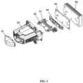
FIG. 2 is an exploded view ofFIG. 1 ; -
FIG. 3 is an exploded view ofFIG. 2 ; -
FIG. 4 is a two-dimensional structure diagram of the brand new general LED traffic headlight with light distribution for a car, a motorcycle, or the like; -
FIG. 5 is a schematic diagram of a free-form surface convergence system inFIG 4 ; and -
FIG. 6 is a schematic diagram of a calculation process of the free-form surface convergence system. - The following reference numerals on the drawings are described below:
- 10 denotes a free-form surface outer lens;
- 20 denotes a decorative frame;
- 30 denotes a baffle; 31 denotes a baffle bearing frame;
- 40 denotes a free-form surface convergence system;
- 50 denotes an LED particle board; and
- 60 denotes a radiator.
- In conjunction with
FIG. 1 to FIG. 4 , a brand new design of a general LED traffic headlight with light distribution for a car, a motorcycle, or the like includes LEDs, a free-formsurface convergence system 40, a different type ofbaffle 30, and a free-form surfaceouter lens 10. The LEDs are installed on anLED particle board 50, the LED particle board is installed on aradiator 60, the radiator is provided with adecorative frame 20, and the free-form surfaceouter lens 10, thebaffle 30, and the free-formsurface convergence system 40 are located in thedecorative frame 20. Thebaffle 30 is installed on a baffle bearingframe 31, and the baffle bearing frame is installed on theradiator 60. - The core of the free-form
surface convergence system 40 is to divide an light incident end of a condenser into different areas in a circumferential direction to carry out separate design in the different areas, thus meeting the lighting requirements of different traffic vehicles at the same time, or meeting the needs of special vehicles for the special lighting effects at different positions in the circumferential direction of the condenser. - As shown in
FIG. 5 , the free-formsurface convergence system 40 divides a small-angle incident light receiving surface into multiple refracting surfaces, so that the refracting surfaces have at least two focal length specifications. The orthogonal projections of the refracting surfaces along the direction of a designed optical axis are sectors with the same center, and the sum of central angles of all the sectors is 360 degrees. A step structure is formed at a junction of every two adjacent refracting surfaces, and a plane passing through the designed optical axis is used as an interface. This method is equivalent to performing circumferential sector partition on the small-angle incident light receiving surface at the light incident end with the designed optical axis as a center, which can make the different areas in the circumferential direction of the condenser have different light collection efficiencies, light utilization rates and lighting effects. Furthermore, the structure is relatively simple, and the light distribution can be quickly controlled, so that the lighting requirements of the different vehicles are met. - After that, the total reflecting surface at the light incident end is further divided into a plurality of total reflection blocks. All the total reflection blocks are segments of rotating surfaces whose rotation axes coincide with the designed optical axis, but there are at least two different plane curves that form the total reflection blocks. The orthographic projections of all the total reflection blocks along the direction of the designed optical axis are sector rings with the same center, and the sum of central angles corresponding to all the sector rings is 360 degrees. A step structure is formed at a junction of every two adjacent total reflection blocks, and a plane passing through the designed optical axis is used as an interface.
- Preferably, the total reflection blocks and the refracting surfaces are in one-to-one correspondence in a radial direction, and the central angles corresponding to the total reflection blocks coincide with the central angles corresponding to the refracting surfaces. After controlling the light distribution of the design of the free-form
surface convergence system 40, the light distribution is projected by means of the free-form surfaceouter lens 10. After corresponding calculation, different regulatory requirements and illumination requirements can be met. - The vehicle lights of the different vehicles are different in traffic lighting requirements and regulatory requirements. In order to achieve a versatile vehicle light design, the main method is to control the free-form
surface convergence system 40, the change of thebaffle 30 and the number of LED particles. - In the aspect of structural design, the free-form
surface convergence system 40 includes a collimator and a free-form surface. - In order to overcome the defect of the traditional LED collimator for a vehicle light in realization of high efficiency, a collimation optimizing lens method is first designed. The optical design of the LED collimator for the vehicle light is based on extended LED light sources. Based on LED point light sources, the LED collimator for the vehicle light is designed as an initial structure. A surface light source is discretized into the several point light sources, and a contour for the LED collimator for the vehicle light is designed for each of the point light sources. The contours for the collimator are respectively multiplied by weight coefficients, the weighted contours are superimposed, and then the superimposed contour is optimized, and the optimized variables are the weight coefficients. A particle swarm optimization algorithm is used to find the best weight ratio, so that the system efficiency is improved. The simulation verification shows that the efficiency can be increased by 20% to 30%. The working principle of the optimized collimator is total reflection. In a process of light transmission, part of the light is transmitted by light using the principle of total reflection. Because the collimator is rotationally axisymmetric, only an upper half part of the collimator is analyzed. As shown in
FIG. 5 , a split line MN divides the light emitted from a point O into two parts. When the light is refracted to the interior through a part ac of an inner wall of an inner hole, the light that reaches an outer contour curve ab of the collimator will be completely reflected by an internal structure of the collimator, and is thus emitted in parallel. The refraction from a center cd of the inner hole to the interior mainly uses an aspheric lens to make the light emitted in parallel on the basis of a design imaging principle of an optical system of an automotive headlight based on a double free-form surface lens. Finally, the two parts of light are emitted in parallel on a light-emitting surface of the collimator, and both the two parts of light are collimated light. - The collimator optimized in the previous step is used to design. A light-emitting window of the collimator is the free-form surface. The free-form surface of the collimator can be used for light shape distribution. The data design of the free-form surface is carried out according to a road surface illumination required by a bus and an intensity value of a 25 m of test point. The surface shape of the free-form surface designed at the light-emitting window of the collimator is designed according to the intensity required by the test point, and then the change in the surface shape of the free-form surface is controlled, so that the intensity values of different demand points are met. The different intensity requirements can be met according to the arbitrary changes of the free-form surface. Intensity value rise and fall as well as width requirement design can be achieved, so as to realize miniaturization and high efficiency in an actual lighting process while meeting the verification of regulations.
- In the design, it is necessary to take into account the common points and similarities between different regulations, and then different needs are met by controlling light distribution. For example, when the automotive road lighting requirements need to be met, the intensity values of all regulatory points shall be taken into account. For example, at the regulatory points such as 75R and 50R, if you want to use the module to meet the lighting needs of motorcycles, the corresponding
baffle 30 and the number of particles need to be replaced, so that the lighting needs of the motorcycles can be met. When the free-formsurface converging system 40 is designed, the illumination changes caused by different numbers of the particles and power have been considered, and different illumination requirements can be met by using such changes. - The above content is only an exemplary implementation of the present invention. For those of ordinary skilled in the art, according to the idea of the present invention, there will be changes in the specific implementations and application scope, and the content of the Description should not be construed as a limitation on the present invention.
Claims (7)
- A general traffic headlight, comprising LEDs, a free-form surface convergence system (40) located in front of the LEDs, a baffle (30) located in front of the free-form surface convergence system, and a free-form surface outer lens (10) located in front of the baffle, wherein the free-form surface convergence system comprises a collimator and a free-form surface; and all light rays are shot into the distance in parallel along an optical axis by the collimator, and the free-form surface at a light-emitting window is employed to design a light shape that meets the regulatory requirements.
- The general traffic headlight according to claim 1, wherein the LEDs are installed on an LED particle board (50), the LED particle board is installed on a radiator (60), the radiator is provided with a decorative frame (20), and the free-form surface outer lens (10), the baffle (30), and the free-form surface convergence system (40) are located in the decorative frame.
- The general traffic headlight according to claim 2, wherein the baffle (30) is installed on a baffle bearing frame (31), and the baffle bearing frame is installed on the radiator (60).
- The general traffic headlight according to claim 1, wherein the free-form surface outer lens (10) is made of silica gel.
- The general traffic headlight according to claim 1, wherein the free-form surface outer lens (10) has an aspheric structure, and a surface equation thereof is as follows:

- The general traffic headlight according to claim 1, wherein based on LED point light sources, an LED collimator for a vehicle light is designed as an initial structure, a surface light source is discretized into the several point light sources, and a contour for the LED collimator for the vehicle light is designed for each of the point light sources; the contours for the collimator are respectively multiplied by weight coefficients, the weighted contours are superimposed, and then the superimposed contour is optimized, and the optimized variables are the weight coefficients; and a particle swarm optimization algorithm is used to find the best weight ratio.
- The general traffic headlight according to claim 6, wherein a surface shape of the free-form surface designed at the light-emitting window of the collimator is designed according to the intensity required by a test point, thus meeting intensity values required by different test points.
Applications Claiming Priority (1)
| Application Number | Priority Date | Filing Date | Title |
|---|---|---|---|
| CN202310093865.6A CN116906844A (en) | 2023-02-10 | 2023-02-10 | General headlight of traffic |
Publications (1)
| Publication Number | Publication Date |
|---|---|
| EP4414764A1 true EP4414764A1 (en) | 2024-08-14 |
Family
ID=85800656
Family Applications (1)
| Application Number | Title | Priority Date | Filing Date |
|---|---|---|---|
| EP23166252.9A Pending EP4414764A1 (en) | 2023-02-10 | 2023-03-31 | General traffic headlight |
Country Status (3)
| Country | Link |
|---|---|
| EP (1) | EP4414764A1 (en) |
| JP (1) | JP7492693B1 (en) |
| CN (1) | CN116906844A (en) |
Citations (3)
| Publication number | Priority date | Publication date | Assignee | Title |
|---|---|---|---|---|
| US20160061398A1 (en) * | 2014-08-26 | 2016-03-03 | Hyundai Mobis Co., Ltd. | Optical structure for vehicle |
| US20210208469A1 (en) * | 2019-08-02 | 2021-07-08 | Giant Leap Holdings, Llc | Light control by means of forced translation, rotation, orientation, and deformation of particles using dielectrophoresis |
| US20220074564A1 (en) * | 2019-05-20 | 2022-03-10 | Hasco Vision Technology Co., Ltd. | Vehicle lamp optical element assembly, vehicle illumination module, vehicle lamp, and vehicle |
Family Cites Families (8)
| Publication number | Priority date | Publication date | Assignee | Title |
|---|---|---|---|---|
| JP4464310B2 (en) * | 2005-04-19 | 2010-05-19 | 株式会社小糸製作所 | Projection type automotive headlamp |
| JP2009087897A (en) * | 2007-10-03 | 2009-04-23 | Harison Toshiba Lighting Corp | Optical component and vehicle lamp using the same |
| US10690311B2 (en) | 2017-01-27 | 2020-06-23 | Maxell, Ltd. | Headlight device |
| CN110494771B (en) * | 2017-02-08 | 2022-01-18 | 巨跃控股有限责任公司 | Light steering and focusing by dielectrophoresis |
| CN110173669B (en) * | 2019-06-25 | 2024-06-18 | 华域视觉科技(上海)有限公司 | Car light optical element assembly, car light and car |
| EP3839324A1 (en) | 2019-12-16 | 2021-06-23 | ZKW Group GmbH | Lighting device for a motor vehicle headlight |
| CN111322580B (en) * | 2020-02-14 | 2022-09-27 | 天津科技大学 | A laser vehicle lamp based on free-form surface lens and its design method |
| CN220506543U (en) * | 2023-02-10 | 2024-02-20 | 上海久科通用配件有限公司 | A general traffic headlight |
-
2023
- 2023-02-10 CN CN202310093865.6A patent/CN116906844A/en active Pending
- 2023-03-31 EP EP23166252.9A patent/EP4414764A1/en active Pending
- 2023-05-06 JP JP2023076418A patent/JP7492693B1/en active Active
Patent Citations (3)
| Publication number | Priority date | Publication date | Assignee | Title |
|---|---|---|---|---|
| US20160061398A1 (en) * | 2014-08-26 | 2016-03-03 | Hyundai Mobis Co., Ltd. | Optical structure for vehicle |
| US20220074564A1 (en) * | 2019-05-20 | 2022-03-10 | Hasco Vision Technology Co., Ltd. | Vehicle lamp optical element assembly, vehicle illumination module, vehicle lamp, and vehicle |
| US20210208469A1 (en) * | 2019-08-02 | 2021-07-08 | Giant Leap Holdings, Llc | Light control by means of forced translation, rotation, orientation, and deformation of particles using dielectrophoresis |
Also Published As
| Publication number | Publication date |
|---|---|
| JP7492693B1 (en) | 2024-05-30 |
| CN116906844A (en) | 2023-10-20 |
| JP2024114565A (en) | 2024-08-23 |
Similar Documents
| Publication | Publication Date | Title |
|---|---|---|
| CN102330948B (en) | Reflector and combined headlamp for LED automobile illumination | |
| CN102606977B (en) | Optical lens with free-form surfaces for LED automobile headlight | |
| CN107036028B (en) | LED automobile dipped headlight with multiple reflection structure | |
| CN103062698B (en) | Ground vehicle area-corresponding pointing light distribution type LED lamp and manufacturing method thereof | |
| CN101858550B (en) | LED light source of dipped headlamp of automobile, with cut-off line | |
| JP7154219B2 (en) | Multifocal collimating lens and headlight assembly for automotive low beam | |
| JP4387783B2 (en) | Projector type headlight | |
| CN211875908U (en) | Optical element, headlamp module, vehicle lamp and vehicle | |
| CN103363418B (en) | The microlens array type headlamp of LED automobile illumination | |
| CN103206668A (en) | Free-form surface lens for projection-type light emitting diode (LED) automobile dipped headlight | |
| CN201706353U (en) | Automotive Optical Module | |
| CN220506543U (en) | A general traffic headlight | |
| CN106989342B (en) | Far and near integrated LED headlights | |
| CN203431672U (en) | LED (Light Emitting Diode) microlens-arrayed headlamp for automotive lighting | |
| EP4414764A1 (en) | General traffic headlight | |
| US20230272899A1 (en) | Small aperture low-beam and high-beam system and methods | |
| CN117469615A (en) | A vehicle low beam lamp and its design method | |
| TWI414726B (en) | Light collecting lens, module and lamp with multiple curvature surfaces | |
| CN116859584A (en) | Design method of free-form surface convergence system | |
| TWI870855B (en) | Vehicle headlight | |
| US7150551B2 (en) | Complex reflector for a vehicle headlamp, and method for the manufacture of the reflector | |
| CN210050733U (en) | Light guide far and near light unit system | |
| CN202868571U (en) | High beam headlamp optical lens used for LED automotive headlamp illumination | |
| TWM648138U (en) | Vehicle headlight | |
| CN209744279U (en) | A bifocal convex lens type high and low beam headlight without moving baffle |
Legal Events
| Date | Code | Title | Description |
|---|---|---|---|
| PUAI | Public reference made under article 153(3) epc to a published international application that has entered the european phase |
Free format text: ORIGINAL CODE: 0009012 |
|
| STAA | Information on the status of an ep patent application or granted ep patent |
Free format text: STATUS: REQUEST FOR EXAMINATION WAS MADE |
|
| 17P | Request for examination filed |
Effective date: 20230331 |
|
| AK | Designated contracting states |
Kind code of ref document: A1 Designated state(s): AL AT BE BG CH CY CZ DE DK EE ES FI FR GB GR HR HU IE IS IT LI LT LU LV MC ME MK MT NL NO PL PT RO RS SE SI SK SM TR |