EP4414687A1 - Optical measuring method, and optical measuring device - Google Patents
Optical measuring method, and optical measuring device Download PDFInfo
- Publication number
- EP4414687A1 EP4414687A1 EP22889776.5A EP22889776A EP4414687A1 EP 4414687 A1 EP4414687 A1 EP 4414687A1 EP 22889776 A EP22889776 A EP 22889776A EP 4414687 A1 EP4414687 A1 EP 4414687A1
- Authority
- EP
- European Patent Office
- Prior art keywords
- measured
- obj
- light
- optical measurement
- pulsed light
- Prior art date
- Legal status (The legal status is an assumption and is not a legal conclusion. Google has not performed a legal analysis and makes no representation as to the accuracy of the status listed.)
- Pending
Links
Images




Classifications
-
- G—PHYSICS
- G01—MEASURING; TESTING
- G01J—MEASUREMENT OF INTENSITY, VELOCITY, SPECTRAL CONTENT, POLARISATION, PHASE OR PULSE CHARACTERISTICS OF INFRARED, VISIBLE OR ULTRAVIOLET LIGHT; COLORIMETRY; RADIATION PYROMETRY
- G01J3/00—Spectrometry; Spectrophotometry; Monochromators; Measuring colours
- G01J3/02—Details
- G01J3/0205—Optical elements not provided otherwise, e.g. optical manifolds, diffusers, windows
- G01J3/0218—Optical elements not provided otherwise, e.g. optical manifolds, diffusers, windows using optical fibers
-
- G—PHYSICS
- G01—MEASURING; TESTING
- G01J—MEASUREMENT OF INTENSITY, VELOCITY, SPECTRAL CONTENT, POLARISATION, PHASE OR PULSE CHARACTERISTICS OF INFRARED, VISIBLE OR ULTRAVIOLET LIGHT; COLORIMETRY; RADIATION PYROMETRY
- G01J3/00—Spectrometry; Spectrophotometry; Monochromators; Measuring colours
- G01J3/02—Details
- G01J3/10—Arrangements of light sources specially adapted for spectrometry or colorimetry
-
- G—PHYSICS
- G01—MEASURING; TESTING
- G01J—MEASUREMENT OF INTENSITY, VELOCITY, SPECTRAL CONTENT, POLARISATION, PHASE OR PULSE CHARACTERISTICS OF INFRARED, VISIBLE OR ULTRAVIOLET LIGHT; COLORIMETRY; RADIATION PYROMETRY
- G01J3/00—Spectrometry; Spectrophotometry; Monochromators; Measuring colours
- G01J3/28—Investigating the spectrum
- G01J3/2803—Investigating the spectrum using photoelectric array detector
-
- G—PHYSICS
- G01—MEASURING; TESTING
- G01N—INVESTIGATING OR ANALYSING MATERIALS BY DETERMINING THEIR CHEMICAL OR PHYSICAL PROPERTIES
- G01N21/00—Investigating or analysing materials by the use of optical means, i.e. using sub-millimetre waves, infrared, visible or ultraviolet light
- G01N21/17—Systems in which incident light is modified in accordance with the properties of the material investigated
- G01N21/25—Colour; Spectral properties, i.e. comparison of effect of material on the light at two or more different wavelengths or wavelength bands
- G01N21/31—Investigating relative effect of material at wavelengths characteristic of specific elements or molecules, e.g. atomic absorption spectrometry
-
- G—PHYSICS
- G01—MEASURING; TESTING
- G01N—INVESTIGATING OR ANALYSING MATERIALS BY DETERMINING THEIR CHEMICAL OR PHYSICAL PROPERTIES
- G01N21/00—Investigating or analysing materials by the use of optical means, i.e. using sub-millimetre waves, infrared, visible or ultraviolet light
- G01N21/84—Systems specially adapted for particular applications
- G01N21/85—Investigating moving fluids or granular solids
-
- G—PHYSICS
- G01—MEASURING; TESTING
- G01N—INVESTIGATING OR ANALYSING MATERIALS BY DETERMINING THEIR CHEMICAL OR PHYSICAL PROPERTIES
- G01N21/00—Investigating or analysing materials by the use of optical means, i.e. using sub-millimetre waves, infrared, visible or ultraviolet light
- G01N21/84—Systems specially adapted for particular applications
- G01N2021/845—Objects on a conveyor
-
- G—PHYSICS
- G01—MEASURING; TESTING
- G01N—INVESTIGATING OR ANALYSING MATERIALS BY DETERMINING THEIR CHEMICAL OR PHYSICAL PROPERTIES
- G01N33/00—Investigating or analysing materials by specific methods not covered by groups G01N1/00 - G01N31/00
- G01N33/02—Food
-
- G—PHYSICS
- G01—MEASURING; TESTING
- G01N—INVESTIGATING OR ANALYSING MATERIALS BY DETERMINING THEIR CHEMICAL OR PHYSICAL PROPERTIES
- G01N33/00—Investigating or analysing materials by specific methods not covered by groups G01N1/00 - G01N31/00
- G01N33/02—Food
- G01N33/14—Beverages
Definitions
- the present disclosure relates to an optical measurement apparatus.
- Spectroscopic analysis has been widely used for component analysis and inspection of target objects.
- a target object is illuminated with measurement light, and a spectrum of object light affected by the target object is measured.
- Optical characteristic such as reflection characteristic (wavelength dependence) or transmission characteristic is obtainable, according to relationship between spectrum of the object light and spectrum of the measurement light.
- Patent Literatures 1 and 2 disclose product inspection apparatuses. These product inspection apparatuses have a pulsed light source structured to illuminate a target object with pulsed light, a photodetector arranged at a position where light from the target object is incident, and a calculator structured to estimate spectral characteristic of the target object according to an output from the photodetector.
- the product inspection apparatus cannot provide accurate spectrometry, unless a timing at which the target object passes through a measurement point synchronizes with a timing of light illumination by the pulsed light source. This requires a mechanism for synchronizing the positioning with the illumination timing, and thus has complicated the device.
- the present disclosure has been made considering the aforementioned problem, and an exemplary object of which is to provide a method and an apparatus capable of accurately measuring an object to be measured in motion without omission, without synchronizing positioning of the object to be measured with the timing of light illumination.
- An optical measurement method includes: a first step of illuminating an illumination area through which an object to be measured passes with pulsed light whose wavelength changes with time, at a predetermined repetition frequency; a second step of detecting, with a photodetector, light from the object to be measured illuminated with the pulsed light in the first step; and
- the optical measurement apparatus includes: an illumination device structured to illuminate an illumination area through which an object to be measured passes with pulsed light whose wavelength changes with time, at a predetermined repetition frequency; and a photodetector structured to detect light from the object to be measured illuminated with the pulsed light; the optical measurement apparatus being structured to use a detection signal generated by the photodetector, for calculating an optical spectrum of the object to be measured, and to satisfy a relational expression f ⁇ D ⁇ d / v ⁇ 2.0 with a repetition frequency of the pulsed light given by f [Hz], an effective size of the object to be measured in a moving direction given by D [m], a moving speed of the object to be measured given by v [m/s], and a size of an illumination spot of the pulsed light on a surface of the object to be measured in the moving direction given by d [m].
- a certain embodiment of the present disclosure can provide a method and a device capable of accurately measuring an object to be measured in motion without omission, with no need for synchronizing positioning of the object to be measured and the timing of light illumination.
- An optical measurement method includes the following processes.
- First step Illuminating an illumination area through which an object to be measured passes with pulsed light whose wavelength changes with time, at a predetermined repetition frequency.
- Second step Detecting, with a photodetector, light from the object to be measured illuminated with the pulsed light in the first step.
- Third step Obtaining an optical spectrum of the object to be measured with reference to a detection signal generated by the photodetector in the second step.
- An optical measurement apparatus has an illumination device structured to illuminate an illumination area through which an object to be measured passes with pulsed light whose wavelength changes with time, at a predetermined repetition frequency, and a photodetector structured to receive light from the object to be measured illuminated with the pulsed light.
- a detection signal generated by the photodetector is used for calculating an optical spectrum of the object to be measured.
- a relational expression of f ⁇ D ⁇ d / v ⁇ 2.0 holds, with the repetition frequency of the pulsed light given by f [Hz], an effective size of the object to be measured in a moving direction given by D [m], a moving speed of the object to be measured given by v [m/s], and a size of an illumination spot of the pulsed light on a surface of the object to be measured in the moving direction given by d [m]. If the object to be measured is in accelerated motion, it suffices to employ average speed for the moving speed v [v/m].
- satisfaction of the relation (1) ensures that at least one shot of pulsed light is incident on the object to be measured in motion, over the duration (pulse width) of the pulse.
- the "effective size” refers to the size of a part of the object to be measured that substantially takes part in the spectrometry.
- the effective size is determined by a region excluding the shielded part, since the shielded part does not take part in the measurement.
- f ⁇ D ⁇ d / v ⁇ 10.0 may hold. This ensures that at least nine shots of pulsed light are incident on the object to be measured. In this case, S/N may be improved by integrating at least nine times of output from the photodetector.
- f ⁇ D ⁇ d / v ⁇ 500.0 may hold. This ensures that at least 499 shots of the pulsed light are incident on the object to be measured in motion.
- S/N may be improved by integrating at least 499 times of output from the photodetector. This is effective in a case where the transmittance is low when measuring transmitted light through the object to be measured.
- f ⁇ D ⁇ d / v ⁇ 5000.0 may hold. This ensures that at least 4999 shots of the pulsed light are incident on the object to be measured in motion.
- S/N may be improved by integrating at least 4999 times of output from the photodetector. This is effective in a case where the transmittance is very low (10% or lower, for example) when measuring transmitted light through the object to be measured.
- v > 0.5 m/s may hold.
- the moving speed of v > 0.5 m/s comes under the category of high speed, in usual application of spectrometry.
- the faster the moving speed the more difficult the control.
- this embodiment with no need for timing adjustment, is particularly useful for applications with fast moving speed.
- the object to be measured may be moved by conveyance with a conveyor. This case is advantageous in terms of easiness of control of the moving speed v.
- the object to be measured may be moved by falling.
- the measurement of the object to be measured, while supporting it with a supporting member or the like, would undesirably shield a part of the light due to the supporting member
- the present system can measure the object to be measured in a free space, thus solving the problem of shielding of light.
- the system can also omit any means for conveying the object to be measured, or can simplify the structure.
- the object to be measured may be moved by sliding on a slope.
- the system can omit any means for conveying the object to be measured, or can simplify the structure.
- the illumination device may have a broadband pulsed light source, and a pulse stretcher structured to stretch a pulse width of the pulsed light emitted from the pulsed light source, so as to establish 1:1 correspondence between a wavelength and an elapsed time per pulse.
- the pulse stretcher may have: an array waveguide grating structured to spatially divide the pulsed light emitted from the pulsed light source corresponding to a wavelength; and a plurality of fibers in a number corresponded to the number of division of wavelength by the arrayed waveguide grating.
- Fig. 1 is a block diagram illustrating an optical measurement apparatus 100 according to an embodiment.
- the optical measurement apparatus 100 is a spectrometer structured to measure a transmission spectrum of an object OBJ, and mainly includes an illumination device 200, a light receiving device 300, a conveyor 400, and a processor 500.
- an illumination device 200 a light receiving device 300
- a conveyor 400 a conveyor
- a processor 500 a processor for controlling the illumination device 200, the light receiving device 300 or the like as a block for simplicity, this does not mean that any components constituting each device are enclosed in a single enclosure.
- the top, bottom, left and right in the drawings do not restrict arrangement of the individual components in the actual optical measurement apparatus 100, or the travel direction of light.
- the illumination device 200 illuminates an illumination area through which an object to be measured OBJ passes, with pulsed light (referred to as measurement light, hereinafter) S IN whose wavelength changes with time, at a predetermined repetition frequency.
- the measurement light S IN has a 1:1 correspondence between time and wavelength. This is stated as “measurement light S IN has uniqueness of wavelength”.
- the illumination device 200 may only be configured with use of any of known techniques, for which those described in Patent Literatures 1 and 2 are applicable.
- the conveyor 400 supports and conveys the object to be measured OBJ.
- the verb "support” encompasses not only physically fixing the object to be measured OBJ, but also holding it within a certain range.
- the object to be measured OBJ moves across the illumination area, with the aid of the conveyor 400.
- the illumination device 200 in this embodiment operates asynchronously with the conveyance of the object to be measured OBJ with the conveyor 400, in other words, runs freely.
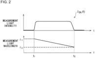
- Fig. 2 is a drawing explaining the measurement light S IN .
- the upper tier of Fig. 2 illustrates intensity (time waveform) I IN (t) of the measurement light S IN
- the lower tier illustrates a temporal change in wavelength ⁇ of the measurement light S IN .
- the measurement light S IN in this example is given by one pulse, having dominant wavelength ⁇ 1 at the leading edge, and dominant wavelength ⁇ 2 at the trailing edge.
- the wavelength changes with time within one pulse between ⁇ 1 and ⁇ 2 .
- the measurement light S IN is given by a positively chirped pulse ( ⁇ 1 > ⁇ 2 ) whose frequency increases with time, in other words, whose wavelength shortens with time.
- the measurement light S IN may alternatively be a negatively chirped pulse whose wavelength becomes longer with time ( ⁇ 1 ⁇ ⁇ 2 ).
- the measurement light S IN is illuminated on a first face (top face) of the object to be measured OBJ, transmitted through the object to be measured OBJ, and emitted as transmitted light (also referred to as object light, hereinafter) S OBJ from a second face (bottom face).
- transmitted light also referred to as object light, hereinafter
- I OBJ ⁇ T ⁇ ⁇ I IN ⁇
- the object light S OBJ may include regular transmitted light and diffuse transmitted light
- this embodiment is particularly suitable for spectrometry of an object OBJ in which the diffuse transmitted light is dominant.
- the regular transmitted light is emitted in the same direction as the optical axis of the measurement light S IN , meanwhile the object light S OBJ , which is the diffuse transmitted light, is widely emitted not only in the direction of the optical axis of the measurement light S IN but also in any direction different therefrom.
- the diffuse transmitted light is emitted with an intensity distribution that follows the cosine characteristic.
- the light receiving device 300 is provided on the opposite side of the illumination device 200 while placing the conveyor 400 in between, and detects the diffuse transmitted light emitted from the second face of the object to be measured OBJ.
- the light receiving device 300 contains a photodetector 302 structured to detect the diffuse transmitted light of the object to be measured OBJ as the object light S OBJ .
- the light receiving device 300 may also contain a condensing optical system or the like, which is however unillustrated in Fig. 1 .
- the photodetector 302 is a photoelectric conversion element that converts optical signal into electric signal, and is exemplified by photodiode, avalanche photodiode, phototransistor, photomultiplier tube making use of a photoelectric effect, and photoconductive element making use of change in electric resistance upon light illumination.
- Output of the photodetector 302 is converted by an A/D converter into digital detection signal, and then supplied to a processor 500.
- the detection signal represents a time waveform I OBJ (t) of the object light S OBJ .
- the processor 500 generates a spectrum I OBJ ( ⁇ ) of the object light S OBJ , from the output signal of the light receiving device 300.
- the processor 500 then calculates transmittance T( ⁇ ) of the object OBJ, with use of the spectrum I IN ( ⁇ ) of the measurement light S IN and the spectrum I OBJ ( ⁇ ) of the object light S OBJ .
- T ⁇ I OBJ ⁇ / I IN ⁇
- the spectrum I IN ( ⁇ ) of the measurement light S IN is obtainable, alternatively by splitting a part of the measurement light S IN to be branched to another route, typically with use of a beam splitter on the side of the object to be measured OBJ closer to the illumination device 200, and by measuring a time waveform I IN (t) of the branched measurement light S IN with use of another light receiving device (not illustrated in Fig. 1 ) other than the light receiving device 300.
- a preliminarily measured spectrum I IN ( ⁇ ) may be held and used.
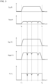
- Fig. 3 is a drawing explaining spectroscopy with use of the optical measurement apparatus 100 illustrated in Fig. 1 . Since the measurement light S IN has the 1:1 correspondence between time t and wavelength A as described previously, so that the waveform I IN (t) on the time-domain basis can be converted into the spectrum I IN ( ⁇ ) on the frequency-domain basis.
- time waveform I OBJ (t) of the object light S OBJ generated from the measurement light S IN will have the 1:1 correspondence between time t and wavelength A.
- the processor 500 can therefore convert the waveform I OBJ (t) of the object light S OBJ given by the output of the light receiving device 300, into the spectrum I OBJ ( ⁇ ) of the object light S OBJ .
- the processor 500 can calculate transmittance T( ⁇ ) of the object to be measured OBJ from I OBJ ( ⁇ )/I IN ( ⁇ ), which is a ratio of two spectra I OBJ ( ⁇ ) and I IN ( ⁇ ).
- Figs. 4(a) and (b) are drawings explaining light illumination in the optical measurement apparatus 100.
- Fig. 4(a) illustrates the object to be measured OBJ and an instantaneous illumination spot SP of the measurement light S IN .
- the object to be measured OBJ actually moves while keeping the illumination spot SP stationary, the description herein will be made on relative movement in which the illumination spot SP moves.
- the object to be measured OBJ and the illumination spot SP herein will be depicted with circles, the shapes thereof are not particularly limited.
- the object light S OBJ emitted through the bottom face of the object to be measured OBJ is shielded by the conveyor 400. That is, the shielded area of the object to be measured OBJ does not take part in the measurement.
- the effective size D of the object to be measured OBJ in this case is given by the width of the opening of the conveyor 400.
- the conveyor 400 illustrated in Fig. 1 has a transparent part that supports and conveys the object to be measured OBJ, the effective size of the object to be measured OBJ will coincide with the actual size of the object to be measured OBJ.
- Fig. 4 (b) illustrates an illumination area A formed by the pulsed light. With the pulse width of the measurement light given by Tp [s], the width of the illumination area A linearly extends with respect to the pulse width Tp.
- Fig. 4 (b) illustrates illumination areas A formed by two temporally adjacent pulses.
- Tr 1/f [s] of the pulsed light.
- f [Hz] represents the repetition frequency of the pulsed light.
- the pulse width Tp of the measurement light is smaller than the period Tr of the light illumination, between which the relation below holds. Tp ⁇ Tr
- Tp/Tr is also referred to as duty cycle.
- the illumination device 200 in this embodiment operates asynchronously with the conveyance of the object to be measured OBJ with the conveyor 400, as described previously.
- at least one shot of pulsed light is necessarily illuminated on the object to be measured OBJ in motion without going out thereof in any situation, over the duration of the pulse (pulse width).
- at least one illumination area A should completely fall within the object to be measured OBJ without going out thereof. Conditions required herein will be described.
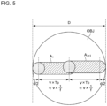
- Fig. 5 is a drawing explaining illumination conditions of the pulsed light.
- the duty cycle of the pulsed measurement light S IN is infinitely close to 1 (that is, Tp ⁇ Tr).
- Fig. 6 is a drawing illustrating an exemplary pulsed light illumination onto the object to be measured. Since the conveyance of the object to be measured OBJ and the illumination of the pulsed light are asynchronous, so that the positional relation between the illumination area A and the object to be measured OBJ drifts in the left-right direction, as illustrated in Fig. 6.
- the center illumination area A i+1 from among the three sequential illumination areas A i , A i+1 and A i+2 , completely falls within the object to be measured OBJ, even if the timing of shot of the pulsed light were shifted ahead or behind on the time axis.
- the illumination area A i which partially goes out of the object to be measured OBJ is considered to lack the first half of the time waveform I OBJ (t) of the object light S OBJ illustrated in Fig. 3 , or to lack information of the object to be measured OBJ.
- the illumination area A i+2 is considered to lack the latter half of the time waveform I OBJ (t) of the object light S OBJ illustrated in Fig. 3 , or to lack information of the object to be measured OBJ.
- the time waveforms I OBJ (t) of the object light S OBJ which correspond to the illumination areas A i and A i+2 are, therefore, preferably omitted, rather than being incorporated in the spectrometry.
- a method of omitting the improper time waveforms I OBJ (t) is not limited.
- the improper time waveforms I OBJ (t) may be left uncaptured by an A/D converter.
- the improper time waveforms I OBJ (t) may be captured by the A/D converter, and then omitted from the integration by way of signal processing. Whether a certain time waveform I OBJ (t) is improper or not may be judged from the waveform. Alternatively, the judgment may be made by monitoring the position of the object to be measured OBJ and the position of the illumination area A.
- the situation illustrated in Fig. 6 can employ the center one of the three temporally sequential shots of pulsed light for the spectrometry.
- the expression (1) is modified to obtain expression (1a) that describes allowable frequency range. f ⁇ 2.0 ⁇ v / D ⁇ d
- relational expression (2) is given as a conditional expression. f ⁇ D ⁇ d / v ⁇ 10.0
- S/N may be improved by integrating at least nine times of output from the photodetector. Meanwhile with small K, the measurement is suitable for obtaining reflection spectrum.
- relational expression (3) is given as a conditional expression.
- S/N may be improved by integrating at least 499 times of output from the photodetector. This is effective in a case where the transmittance is low when measuring transmitted light through the object to be measured OBJ.
- relational expression (4) is given as a conditional expression. f ⁇ D ⁇ d / v ⁇ 5000.0
- S/N may be improved by integrating at least 4999 times of output from the photodetector. This is effective in a case where the transmittance is very low (10% or lower, for example) when measuring transmitted light through the object to be measured OBJ.
- optical measurement apparatus 100 The structure and operation of the optical measurement apparatus 100 have been described. Next, experiments with use of the optical measurement apparatus 100 will be described.
- the illumination device 200 is a pulse spectroscopic light source equipped with an array waveguide grating (AWG).
- the pulsed light S IN has a wavelength of 900 to 1300 nm, and a stretching time of 0.5 ⁇ s (50 channels at 2 m intervals).
- the repetition frequency f of the pulsed light is variable.
- Size D of the object to be measured OBJ in the moving direction (a part exposed as a face to be illuminated): 11 mm
- Size D of the object to be measured OBJ in the moving direction (a part exposed as a face to be illuminated): 1.1 mm
- Spot size d of the pulsed light on the face of the object to be measured OBJ 0.1 mm
- FIG. 8 is a diagram illustrating an inspection apparatus 800 as a mode of the optical measurement apparatus 100.
- the inspection apparatus 800 inspects a large amount of products P such as food and beverage, and determines the quality. Food and beverage have a transmittance on the order of 1/100 to 1/1000.
- the inspection apparatus 800 has the illumination device 200, the light receiving device 300, the conveyor 400, and the processor 500.
- the inspection apparatus 800 additionally has a light receiving device 810, a beam damper 820, a digitizer 830, and a pump 840.
- the illumination device 200 has a light source 210, a pulse stretcher 220, and an illumination optical system 230.
- the light source 210 produces a continuous spectrum of at least 10 nm bandwidth, and more specifically produces a broad coherent pulsed light in an infrared region from 900 to 1300 nm.
- the light source 210 may be a super continuum (SC) light source having a pulsed laser and a non-linear element.
- the pulsed laser usable here includes mode locked laser, microchip laser, and fiber laser.
- the non-linear element usable here includes non-linear fiber such as photonic crystal fiber.
- the pulse stretcher 220 stretches the pulse width of the pulsed light generated by the light source 210, so as to establish the 1:1 correspondence between time and wavelength.
- the pulse stretcher 220 may be constituted by a single wavelength dispersion fiber.
- the pulse stretcher 220 may be constituted by a demultiplexer that branches the pulsed light into a plurality of paths wavelength by wavelength, a plurality of fibers (a fiber bundle) that gives different delays to the plurality of paths, and a multiplexer that recombines outputs of the plurality of fibers.
- the demultiplexer may be constituted by a planar lightwave circuits (PLC), and more specifically by an array waveguide grating (AWG). The individual fibers that constitute the fiber bundle have different lengths.
- each support part 401 has a recess 410.
- a plurality of products P are placed in the recesses 410 with use of a mounter (not illustrated), on the upstream side (left side in the drawing).
- the conveyor 400 conveys the plurality of support parts 401 in the direction of arrangement thereof (rightwards in the drawing).
- the faces of the recess 410 the surface on which the product P is placed will be referred to as a top face, and the opposite surface will be referred to as a back face.
- the illumination optical system 230 illuminates the illumination region 10 with stretched pulses used as the measurement light S IN .
- the illumination region 10 is situated at a point where the product P passes, that is, where the recess 410 passes.
- the illumination optical system 230 may be constituted by a transmission optical system such as a lens, a reflection optical system such as a mirror, or a combination thereof. With movement of the recess 410, the products P sequentially pass across the illumination region 10.
- the light source 210 repeatedly generates the pulsed light at a predetermined frequency (period).
- Operating frequency of the light source 210 may only be determined according to the moving speed of the recess 410, or, the conveying speed of the products P, so that a plurality of shots of measurement light S IN will be illuminated on the same product P while the product P resides in the illumination region 10. More specifically, the repetition frequency f is determined so as to satisfy the aforementioned relational expression (1).
- Operation of the light source 210 is independent of operation of the conveyor 400, in other words, position of the products P.
- the measurement light S IN is, therefore, repeatedly illuminated on the illumination region 10, even if the product P is not placed in the recess 410.
- the light receiving device 300 is provided above the recess 410.
- the recess 410 has a through-hole 412 formed in the bottom face.
- the through-hole 412 is formed to guide the measurement light S IN from the illumination optical system 230, to the bottom face of the product P.
- a part of the product P as the object to be measured which takes part in the spectrometry, in other words, a part exposed to be illuminated by the measurement light S IN (pulsed light) corresponds to the through-hole 412.
- the size (diameter) of the through-hole 412 rather than the size (diameter) of the product P, gives the effective size D of the product P.
- a pump 840 may be provided on the back side of the recess 410.
- the pump 840 constitutes a suction unit, with which the back side of the recess 410 is evacuated to produce a negative pressure, making the product P adhere to the recess 410, thereby preventing the product P from falling off from the recess 410 as the product P is conveyed.
- the light receiving device 300 measures a time waveform I OBJ (t) of the object light S OBJ .
- a beam damper 820 to prevent stray light.
- the light receiving device 810 is provided to measure the spectrum of the measurement light S IN .
- the illumination optical system 230 branches a part of the measurement light S IN into a separate arm as the reference light S REF , typically with use of a beam splitter.
- the light receiving device 810 measures a time waveform I REF (t) of the reference light S REF branched into the separate arm.
- the time waveform I REF (t) is equivalent to the time waveform I IN (t) of the measurement light S IN .
- the digitizer 830 having an A/D converter, samples outputs of the light receiving device 300 and the light receiving device 810, that is, time waveforms I OBJ (T) and I REF (t), respectively, at a predetermined sampling frequency, and converts them respectively into waveform data D OBJ (t) and D IN (t) of digital signals.
- the digitizer 830 is omissible, when using the light receiving devices 300 and 810 designed for digital output.
- the processor 500 processes the digital waveform data D OBJ (t) and D IN (t) to obtain a transmission characteristic (or absorption characteristic) T( ⁇ ) of the product P.
- the processor 500 may be implemented by a general-purpose or dedicated computer having a processor, a memory, and a storage medium such as hard disk, while combined with software program. The processing by the processor 500 is as described above.
- the transmission spectrum of the product P may be accurately measured, without synchronizing the timing of conveyance of the product P with the timing of light illumination by the illumination device 200.
- the object light S OBJ may be prevented from being shielded by the through-hole 412, thereby enabling detection of much more object light S OBJ by the light receiving device 300.
- the measurement light S IN will leak through the through-hole 412 towards the light receiving device 300.
- the light receiving device 300 were arranged on the optical axis OA2 of the measurement light S IN , and no product P were placed on the optical axis OA2, the high-intensity measurement light S IN would be incident directly on the photodetector 302. This is not desirable.
- the light receiving device 300 is preferably structured to avoid incidence of the measurement light S IN on the photodetector 302, when there is no product P placed in the recess 410.
- the light receiving device 300 is structured so that a component S ⁇ of the diffuse transmitted light (object light S OBJ ) of the object to be measured OBJ, which is emitted in a direction deviated from the optical axis OA2 of the measurement light S IN (with deviation angle ⁇ ), is incident on the photodetector 302.
- the light receiving device 300 may thus be protected even in the absence of the product P in the recess 410.
- the light source 210 of the illumination device 200 in this case may be allowed to freely run asynchronously with the operation of the conveyor 400, and also there is no need for shutter control in synchronization with the operation of the conveyor 400.
- Fig. 9 is a diagram illustrating an optical measurement apparatus 100A according to Modified Example 1.
- the light receiving device 300 is arranged to detect reflected light on the object to be measured OBJ as the object light S OBJ .
- neither the measurement light S IN nor the object light S OBJ is shielded, so that the effective size of the object to be measured OBJ coincides with the actual size of the object to be measured OBJ.
- a mode of supporting and transfer of the product P is not limited thereto.
- the product P may move while being placed on a roller conveyor or on a simple belt. In this case, the intervals between the adjacent products P will become non-uniform, and this makes it difficult to predict the time the object to be measured OBJ passes through the illumination region. Even in such situation, the spectrum of the object to be measured OBJ may be accurately measured, by determining the illumination repetition frequency f so as to satisfy the expression (1).
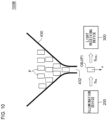
- Fig. 10 is a diagram illustrating an optical measurement apparatus 100B according to Modified Example 3.
- the optical measurement apparatus 100B has a drop-type transfer device 430.
- the object to be measured OBJ falls from a drop port 432 of the transfer device 430.
- the object to be measured OBJ when freely falls, is in accelerated motion.
- the illumination device 200 illuminates the object to be measured OBJ, during falling in a free space, with the measurement light S IN at the repetition frequency f.
- the light receiving device 300 measures the transmitted light or reflected light from the object to be measured OBJ.
- the velocity v in the expression (1) may be an average speed or a maximum speed when intercepting the measurement light S IN .
- neither the measurement light S IN nor the object light S OBJ is shielded, so that the effective size of the object to be measured OBJ coincides with the actual size of the object to be measured OBJ.
- Modified Example 3 can measure the object to be measured OBJ in the free space, and can therefore solve the problem of light shielding. Another advantage is that the means for conveying the object to be measured OBJ is omissible, or that the structure may be simplified.
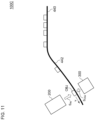
- Fig. 11 is a diagram illustrating an optical measurement apparatus 100C according to Modified Example 4.
- the optical measurement apparatus 100C has a transfer device 440.
- the transfer device 440 has a slope 442.
- the object to be measured OBJ slides on the slope 442 so as to move across the illumination range of the illumination device 200.
- the light receiving device 300 measures the transmitted light or reflected light from the object to be measured OBJ.
- the velocity v in the expression (1) may only be an average speed or a maximum speed when intercepting the measurement light S IN .
- OBJ object to be measured P product, 100 optical measurement apparatus, 200 illumination device, 210 light source, 220 pulse stretcher, 230 illumination optical system, 300 light receiving device, 302 photodetector, 400 conveyor, 401 support part, 410 recess, 412 through-hole, 430 transfer device, 432 drop port, 440 transfer device, 442 slope, 500 processor, 800 inspection apparatus, 810 light receiving device, S IN measurement light, S OBJ object light, 820 beam damper, 830 digitizer, 840 pump
Landscapes
- Physics & Mathematics (AREA)
- Spectroscopy & Molecular Physics (AREA)
- General Physics & Mathematics (AREA)
- Biochemistry (AREA)
- Chemical & Material Sciences (AREA)
- Analytical Chemistry (AREA)
- Life Sciences & Earth Sciences (AREA)
- General Health & Medical Sciences (AREA)
- Health & Medical Sciences (AREA)
- Immunology (AREA)
- Pathology (AREA)
- Investigating Or Analysing Materials By Optical Means (AREA)
- Spectrometry And Color Measurement (AREA)
Abstract
Description
- The present disclosure relates to an optical measurement apparatus.
- Spectroscopic analysis has been widely used for component analysis and inspection of target objects. In the spectroscopic analysis, a target object is illuminated with measurement light, and a spectrum of object light affected by the target object is measured. Optical characteristic such as reflection characteristic (wavelength dependence) or transmission characteristic is obtainable, according to relationship between spectrum of the object light and spectrum of the measurement light.
-
Patent Literatures -
- [Patent Literature 1]
JP 2020-159971 A - [Patent Literature 2]
JP 2020-159973 A - The product inspection apparatus cannot provide accurate spectrometry, unless a timing at which the target object passes through a measurement point synchronizes with a timing of light illumination by the pulsed light source. This requires a mechanism for synchronizing the positioning with the illumination timing, and thus has complicated the device.
- The present disclosure has been made considering the aforementioned problem, and an exemplary object of which is to provide a method and an apparatus capable of accurately measuring an object to be measured in motion without omission, without synchronizing positioning of the object to be measured with the timing of light illumination.
- An optical measurement method according to an aspect of the present disclosure includes: a first step of illuminating an illumination area through which an object to be measured passes with pulsed light whose wavelength changes with time, at a predetermined repetition frequency; a second step of detecting, with a photodetector, light from the object to be measured illuminated with the pulsed light in the first step; and
- a third step of obtaining an optical spectrum of the object to be measured with reference to a detection signal generated by the photodetector in the second step. A relational expression of

- holds, with the repetition frequency of a pulsed light given by f [Hz], an effective size of the object to be measured OBJ in a moving direction given by D [m], a moving speed of the object to be measured OBJ given by v [m/s], and a size of an illumination spot of the pulsed light on a surface of the object to be measured OBJ in the moving direction given by d [m].
- Another aspect of the present disclosure relates to an optical measurement apparatus. The optical measurement apparatus includes: an illumination device structured to illuminate an illumination area through which an object to be measured passes with pulsed light whose wavelength changes with time, at a predetermined repetition frequency; and a photodetector structured to detect light from the object to be measured illuminated with the pulsed light; the optical measurement apparatus being structured to use a detection signal generated by the photodetector, for calculating an optical spectrum of the object to be measured, and to satisfy a relational expression

- Note also free combinations of these constituents, and also any of the constituents and expressions exchanged among the method, apparatus and system, are valid as the embodiments of the present invention.
- A certain embodiment of the present disclosure can provide a method and a device capable of accurately measuring an object to be measured in motion without omission, with no need for synchronizing positioning of the object to be measured and the timing of light illumination.
-
- [
Fig. 1] Fig. 1 is a block diagram illustrating an optical measurement apparatus according to an embodiment. - [
Fig. 2] Fig. 2 is a diagram explaining measurement light SIN. - [
Fig. 3] Fig. 3 is a drawing explaining spectroscopy with use of the optical measurement apparatus illustrated inFig. 1 . - [
Fig. 4] Figs. 4(a) and (b) are drawings explaining light illumination in the optical measurement apparatus. - [
Fig. 5] Fig. 5 is a drawing explaining illumination conditions of a pulsed light. - [
Fig. 6] Fig. 6 is a drawing illustrating an exemplary pulsed light illumination onto an object to be measured. - [
Fig. 7] Figs. 7(a) and (b) are charts summarizing experimental results underCondition 1 andCondition 2. - [
Fig. 8] Fig. 8 is a diagram illustrating an inspection apparatus as a mode of the optical measurement apparatus. - [
Fig. 9] Fig. 9 is a diagram illustrating an optical measurement apparatus according to Modified Example 1. - [
Fig. 10] Fig. 10 is a diagram illustrating an optical measurement apparatus according to Modified Example 3. - [
Fig. 11] Fig. 11 is a diagram illustrating an optical measurement apparatus according to Modified Example 4. - Some exemplary embodiments of the present disclosure will be outlined. This outline is intended for briefing some concepts of one or more embodiments, for the purpose of basic understanding of the embodiments, as an introduction before detailed description that follows, without limiting the scope of the invention or disclosure. This outline is not an extensive overview of all possible embodiments, and is therefore intended neither to specify key elements of all embodiments, nor to delineate the scope of some or all of the embodiments. For convenience, the term "one embodiment" may be used to designate one embodiment (Example or Modified Example), or a plurality of embodiments (Examples or Modified Examples) disclosed in this specification.
- An optical measurement method according to one embodiment includes the following processes.
- First step: Illuminating an illumination area through which an object to be measured passes with pulsed light whose wavelength changes with time, at a predetermined repetition frequency.
- Second step: Detecting, with a photodetector, light from the object to be measured illuminated with the pulsed light in the first step.
- Third step: Obtaining an optical spectrum of the object to be measured with reference to a detection signal generated by the photodetector in the second step.
- A relational expression (1) below

- An optical measurement apparatus according to one embodiment has an illumination device structured to illuminate an illumination area through which an object to be measured passes with pulsed light whose wavelength changes with time, at a predetermined repetition frequency, and a photodetector structured to receive light from the object to be measured illuminated with the pulsed light. A detection signal generated by the photodetector is used for calculating an optical spectrum of the object to be measured. A relational expression of

- In a case where the pulsed light is illuminated asynchronously with motion of the object to be measured in the optical measurement apparatus/method according to one embodiment, satisfaction of the relation (1) ensures that at least one shot of pulsed light is incident on the object to be measured in motion, over the duration (pulse width) of the pulse.
- This enables accurate measurement of the object to be measured without omission, with no need for synchronizing positioning of the object to be measured and the timing of illumination.
- Now, the "effective size" refers to the size of a part of the object to be measured that substantially takes part in the spectrometry. In an exemplary case where a part or whole of the light is shielded on the incident side of the pulsed light onto the object to be measured, or on the outgoing side of the light from the object to be measured, the effective size is determined by a region excluding the shielded part, since the shielded part does not take part in the measurement.
- In one embodiment,

- In one embodiment,

- In one embodiment,

- In one embodiment, v > 0.5 m/s may hold.
- The moving speed of v > 0.5 m/s comes under the category of high speed, in usual application of spectrometry. When controlling the timing of illumination in synchronization with positioning of the object to be measured, the faster the moving speed, the more difficult the control. In contrast, this embodiment, with no need for timing adjustment, is particularly useful for applications with fast moving speed.
- In one embodiment, the object to be measured may be moved by conveyance with a conveyor. This case is advantageous in terms of easiness of control of the moving speed v.
- In one embodiment, the object to be measured may be moved by falling. Although the measurement of the object to be measured, while supporting it with a supporting member or the like, would undesirably shield a part of the light due to the supporting member, the present system can measure the object to be measured in a free space, thus solving the problem of shielding of light. The system can also omit any means for conveying the object to be measured, or can simplify the structure.
- In one embodiment, the object to be measured may be moved by sliding on a slope. Thus the system can omit any means for conveying the object to be measured, or can simplify the structure.
- In one embodiment, the illumination device may have a broadband pulsed light source, and a pulse stretcher structured to stretch a pulse width of the pulsed light emitted from the pulsed light source, so as to establish 1:1 correspondence between a wavelength and an elapsed time per pulse.
- In one embodiment, the pulse stretcher may have: an array waveguide grating structured to spatially divide the pulsed light emitted from the pulsed light source corresponding to a wavelength; and a plurality of fibers in a number corresponded to the number of division of wavelength by the arrayed waveguide grating.
- The present disclosure will be explained below on the basis of preferred embodiments, referring to the attached drawings. All constituents, members and processes illustrated in the individual drawings will be given same reference numerals, so as to properly avoid redundant explanations. The embodiments are merely illustrative, and are not restrictive about the disclosure. All features and combinations thereof described in the embodiments are not always essential to the disclosure.
- Dimensions (thickness, length, width, etc.) of the individual members illustrated in the drawings may be appropriately enlarged or shrunk for easy understanding. Furthermore, the dimensions of the plurality of members do not necessarily indicate the dimensional relationship among them, so that a certain member A, if depicted thicker than another member B in a drawing, may even be thinner than the member B.
-
Fig. 1 is a block diagram illustrating anoptical measurement apparatus 100 according to an embodiment. Theoptical measurement apparatus 100 is a spectrometer structured to measure a transmission spectrum of an object OBJ, and mainly includes anillumination device 200, alight receiving device 300, aconveyor 400, and aprocessor 500. Although some drawings will occasionally depict theillumination device 200, thelight receiving device 300 or the like as a block for simplicity, this does not mean that any components constituting each device are enclosed in a single enclosure. Also note that the top, bottom, left and right in the drawings do not restrict arrangement of the individual components in the actualoptical measurement apparatus 100, or the travel direction of light. - The
illumination device 200 illuminates an illumination area through which an object to be measured OBJ passes, with pulsed light (referred to as measurement light, hereinafter) SIN whose wavelength changes with time, at a predetermined repetition frequency. The measurement light SIN has a 1:1 correspondence between time and wavelength. This is stated as "measurement light SIN has uniqueness of wavelength". Theillumination device 200 may only be configured with use of any of known techniques, for which those described inPatent Literatures - The
conveyor 400 supports and conveys the object to be measured OBJ. Now the verb "support" encompasses not only physically fixing the object to be measured OBJ, but also holding it within a certain range. The object to be measured OBJ moves across the illumination area, with the aid of theconveyor 400. Theillumination device 200 in this embodiment operates asynchronously with the conveyance of the object to be measured OBJ with theconveyor 400, in other words, runs freely. -
Fig. 2 is a drawing explaining the measurement light SIN. The upper tier ofFig. 2 illustrates intensity (time waveform) IIN(t) of the measurement light SIN, and the lower tier illustrates a temporal change in wavelength λ of the measurement light SIN. - The measurement light SIN in this example is given by one pulse, having dominant wavelength λ1 at the leading edge, and dominant wavelength λ2 at the trailing edge. The wavelength changes with time within one pulse between λ1 and λ2. In this example, the measurement light SIN is given by a positively chirped pulse (λ1 > λ2) whose frequency increases with time, in other words, whose wavelength shortens with time. Note that the measurement light SIN may alternatively be a negatively chirped pulse whose wavelength becomes longer with time (λ1 < λ2).
- Referring now back to
Fig. 1 . The measurement light SIN is illuminated on a first face (top face) of the object to be measured OBJ, transmitted through the object to be measured OBJ, and emitted as transmitted light (also referred to as object light, hereinafter) SOBJ from a second face (bottom face). With a spectrum of the measurement light SIN given as IIN(λ), and with a wavelength dependence of the transmittance of the object light SOBJ given as T(A), a spectrum IOBJ(λ) of the object light SOBJ is given by the equation below.
- Although the object light SOBJ may include regular transmitted light and diffuse transmitted light, this embodiment is particularly suitable for spectrometry of an object OBJ in which the diffuse transmitted light is dominant. The regular transmitted light is emitted in the same direction as the optical axis of the measurement light SIN, meanwhile the object light SOBJ, which is the diffuse transmitted light, is widely emitted not only in the direction of the optical axis of the measurement light SIN but also in any direction different therefrom. For example, with the direction of the optical axis given by 0°, the diffuse transmitted light is emitted with an intensity distribution that follows the cosine characteristic.
- The
light receiving device 300 is provided on the opposite side of theillumination device 200 while placing theconveyor 400 in between, and detects the diffuse transmitted light emitted from the second face of the object to be measured OBJ. Thelight receiving device 300 contains aphotodetector 302 structured to detect the diffuse transmitted light of the object to be measured OBJ as the object light SOBJ. Besides thephotodetector 302, thelight receiving device 300 may also contain a condensing optical system or the like, which is however unillustrated inFig. 1 . - The
photodetector 302 is a photoelectric conversion element that converts optical signal into electric signal, and is exemplified by photodiode, avalanche photodiode, phototransistor, photomultiplier tube making use of a photoelectric effect, and photoconductive element making use of change in electric resistance upon light illumination. - Output of the
photodetector 302 is converted by an A/D converter into digital detection signal, and then supplied to aprocessor 500. The detection signal represents a time waveform IOBJ(t) of the object light SOBJ. - The
processor 500 generates a spectrum IOBJ(λ) of the object light SOBJ, from the output signal of thelight receiving device 300. Theprocessor 500 then calculates transmittance T(λ) of the object OBJ, with use of the spectrum IIN(λ) of the measurement light SIN and the spectrum IOBJ(λ) of the object light SOBJ.
- The spectrum IIN(λ) of the measurement light SIN is obtainable, alternatively by splitting a part of the measurement light SIN to be branched to another route, typically with use of a beam splitter on the side of the object to be measured OBJ closer to the
illumination device 200, and by measuring a time waveform IIN(t) of the branched measurement light SIN with use of another light receiving device (not illustrated inFig. 1 ) other than thelight receiving device 300. Alternatively in a case with high stability of the measurement light SIN, a preliminarily measured spectrum IIN(λ) may be held and used. -
Fig. 3 is a drawing explaining spectroscopy with use of theoptical measurement apparatus 100 illustrated inFig. 1 . Since the measurement light SIN has the 1:1 correspondence between time t and wavelength A as described previously, so that the waveform IIN (t) on the time-domain basis can be converted into the spectrum IIN(λ) on the frequency-domain basis. - Also the time waveform IOBJ(t) of the object light SOBJ generated from the measurement light SIN will have the 1:1 correspondence between time t and wavelength A. The
processor 500 can therefore convert the waveform IOBJ(t) of the object light SOBJ given by the output of thelight receiving device 300, into the spectrum IOBJ(λ) of the object light SOBJ. - The
processor 500 can calculate transmittance T(λ) of the object to be measured OBJ from IOBJ(λ)/IIN(λ), which is a ratio of two spectra IOBJ(λ) and IIN(λ). - Given that the relation between time t and wavelength A in the measurement light SIN is expressed by a function A = f(t). Most simply, the wavelength A varies linearly with time t according to a linear function. Lowering of the time waveform IOBJ(t) of the object light SOBJ at a certain time tx means that the transmission spectrum T(λ) has an absorption spectrum at a wavelength λx = f(tx).
- Note that the processing in the
processor 500 is not limited thereto. The transmission spectrum T(λ) may be calculated alternatively by calculating T(t) = IOBJ(t)/IIN(t), which is the ratio of two time waveforms IOBJ(t) and IIN(t), and then by converting a variable t of the time waveform T(t) into A. -
Figs. 4(a) and (b) are drawings explaining light illumination in theoptical measurement apparatus 100.Fig. 4(a) illustrates the object to be measured OBJ and an instantaneous illumination spot SP of the measurement light SIN. Although the object to be measured OBJ actually moves while keeping the illumination spot SP stationary, the description herein will be made on relative movement in which the illumination spot SP moves. While the object to be measured OBJ and the illumination spot SP herein will be depicted with circles, the shapes thereof are not particularly limited. - Letting the effective size in the moving direction (rightward in the drawing) of the object to be measured OBJ be D [m], and the moving speed of the object to be measured OBJ be v [m/s]. Referring to
Fig. 1 , the object light SOBJ emitted through the bottom face of the object to be measured OBJ is shielded by theconveyor 400. That is, the shielded area of the object to be measured OBJ does not take part in the measurement. The effective size D of the object to be measured OBJ in this case is given by the width of the opening of theconveyor 400. - If the
conveyor 400 illustrated inFig. 1 has a transparent part that supports and conveys the object to be measured OBJ, the effective size of the object to be measured OBJ will coincide with the actual size of the object to be measured OBJ. - Referring now back to
Figs. 4(a) and (b) . Letting the size of the illumination spot of the measurement light SIN in the moving direction, on the face of the object to be measured OBJ, be d [m]. Assume that a relational expression d < D holds.Fig. 4 (b) illustrates an illumination area A formed by the pulsed light. With the pulse width of the measurement light given by Tp [s], the width of the illumination area A linearly extends with respect to the pulse width Tp. -
Fig. 4 (b) illustrates illumination areas A formed by two temporally adjacent pulses. The interval between the two illumination areas A becomes longer, corresponding to the repetition period Tr = 1/f [s] of the pulsed light. Now, f [Hz] represents the repetition frequency of the pulsed light. The pulse width Tp of the measurement light is smaller than the period Tr of the light illumination, between which the relation below holds.
- Tp/Tr is also referred to as duty cycle.
- The
illumination device 200 in this embodiment operates asynchronously with the conveyance of the object to be measured OBJ with theconveyor 400, as described previously. In this case, at least one shot of pulsed light is necessarily illuminated on the object to be measured OBJ in motion without going out thereof in any situation, over the duration of the pulse (pulse width). In other words, as illustrated inFig. 4(b) , at least one illumination area A should completely fall within the object to be measured OBJ without going out thereof. Conditions required herein will be described. -
Fig. 5 is a drawing explaining illumination conditions of the pulsed light. Consider now a case where the duty cycle of the pulsed measurement light SIN is infinitely close to 1 (that is, Tp ≈ Tr).Fig. 5 illustrates a state in which both illumination areas Ai and Ai+1 formed by two (K = 2) temporally sequential shots of pulsed light fall within the object to be measured OBJ without going out thereof. In this state, the following equation holds.
- In this case, two (K = 2) shots of pulsed light are used for the spectrometry.
-
Fig. 6 is a drawing illustrating an exemplary pulsed light illumination onto the object to be measured. Since the conveyance of the object to be measured OBJ and the illumination of the pulsed light are asynchronous, so that the positional relation between the illumination area A and the object to be measured OBJ drifts in the left-right direction, as illustrated inFig. 6. Fig. 6 illustrates illumination areas Ai, Ai+1, and Ai+2 formed by three (= K + 1) temporally sequential shots of pulsed light. In a case where the aforementioned equation holds, the center illumination area Ai+1, from among the three sequential illumination areas Ai, Ai+1 and Ai+2, completely falls within the object to be measured OBJ, even if the timing of shot of the pulsed light were shifted ahead or behind on the time axis. - In the situation illustrated in
Fig. 6 , the illumination area Ai which partially goes out of the object to be measured OBJ is considered to lack the first half of the time waveform IOBJ(t) of the object light SOBJ illustrated inFig. 3 , or to lack information of the object to be measured OBJ. Similarly, also the illumination area Ai+2 is considered to lack the latter half of the time waveform IOBJ(t) of the object light SOBJ illustrated inFig. 3 , or to lack information of the object to be measured OBJ. - The time waveforms IOBJ(t) of the object light SOBJ which correspond to the illumination areas Ai and Ai+2 are, therefore, preferably omitted, rather than being incorporated in the spectrometry. A method of omitting the improper time waveforms IOBJ(t) is not limited. For example, the improper time waveforms IOBJ(t) may be left uncaptured by an A/D converter. Alternatively, the improper time waveforms IOBJ(t) may be captured by the A/D converter, and then omitted from the integration by way of signal processing. Whether a certain time waveform IOBJ(t) is improper or not may be judged from the waveform. Alternatively, the judgment may be made by monitoring the position of the object to be measured OBJ and the position of the illumination area A.
- In this way, the situation illustrated in
Fig. 6 can employ the center one of the three temporally sequential shots of pulsed light for the spectrometry. - The discussion above teaches that a condition under which one illumination area A always falls within the object to be measured OBJ in any situation, in other words, a condition under which at least one shot of pulsed light is illuminated on the object to be measured OBJ over the duration of the pulse (pulse width) Tp, is given by

- With f, D, d and v specified so as to satisfy the relational expression (1), it now becomes possible to accurately measure the object to be measured OBJ in motion without omission, with no need for synchronizing positioning of the object to be measured and the timing of illumination.
- The expression (1) is modified to obtain expression (1a) that describes allowable frequency range.

- While the discussion above has dealt with a condition under which one object to be measured OBJ is reliably illuminated with one shot of pulsed light, the expression (1a) can be generalized by incorporating an arbitrary constant K (K ≥ 2) to obtain equation (1b).

- With the repetition frequency f specified so as to satisfy the equation (1b), it is ensured that at least (K - 1) shots of pulse are illuminated on the object to be measured OBJ, over the entire ranges of the individual pulse widths. As the constant K made larger, the number of shots of the pulsed light incident on one object to be measured OBJ increases, thus improving SIN.
- For example, with K ≥ 10, then relational expression (2) is given as a conditional expression.

- This ensures that at least nine shots of pulsed light are incident on the object to be measured. In this case, S/N may be improved by integrating at least nine times of output from the photodetector. Meanwhile with small K, the measurement is suitable for obtaining reflection spectrum.
- For example, with K ≥ 500, then relational expression (3) is given as a conditional expression.

- This ensures that at least 499 shots of the pulsed light are incident on the object to be measured in motion. In this case, S/N may be improved by integrating at least 499 times of output from the photodetector. This is effective in a case where the transmittance is low when measuring transmitted light through the object to be measured OBJ.
- For example, with K ≥ 5000, then relational expression (4) is given as a conditional expression.

- This ensures that at least 4999 shots of the pulsed light are incident on the object to be measured in motion. In this case, S/N may be improved by integrating at least 4999 times of output from the photodetector. This is effective in a case where the transmittance is very low (10% or lower, for example) when measuring transmitted light through the object to be measured OBJ.
- The structure and operation of the
optical measurement apparatus 100 have been described. Next, experiments with use of theoptical measurement apparatus 100 will be described. - The
illumination device 200 is a pulse spectroscopic light source equipped with an array waveguide grating (AWG). The pulsed light SIN has a wavelength of 900 to 1300 nm, and a stretching time of 0.5 µs (50 channels at 2 m intervals). The repetition frequency f of the pulsed light is variable. - The experiment was conducted with use of 100 object to be measured OBJ (n = 100), under two types of
conditions - Size D of the object to be measured OBJ in the moving direction (a part exposed as a face to be illuminated): 11 mm
- Spot size d of the pulsed light on the face of the object to be measured OBJ: 1 mm
- Moving speed v of the object to be measured OBJ: 1 m/s
- Intervals between the object to be measured OBJ: 1.57 mm
- A detection signal of the
photodetector 302 was acquired with a digitizer, a gate signal (width = 11 msec, period = 12.57 msec) synchronized with the movement of the object to be measured OBJ was input to the digitizer, and data was collected during ON-time of the gate signal, while triggered with a seed laser, at a capture time of 0.5 psec. - Size D of the object to be measured OBJ in the moving direction (a part exposed as a face to be illuminated): 1.1 mm Spot size d of the pulsed light on the face of the object to be measured OBJ: 0.1 mm
- Moving speed v of the object to be measured OBJ: 10 m/s
- Intervals between the object to be measured OBJ: 11.47 mm
- Under
condition 2, a gate signal having a width of 0.11 msec and a period of 1.257 msec was used. The capture time was 0.5 psec. -
Figs. 7(a) and (b) are chart summarizing experimental results obtained underCondition 1 andCondition 2. Reference will now be made onFig. 7(a) . Fifty percent (50 pieces) of the object to be measured OBJ failed to yield accurate spectra at f = 50 Hz, whereas all of 100 pieces of the object to be measured OBJ accurately went through the spectrometry at 100 Hz, 200 Hz, and 1 kHz. - Reference will then be made on
Fig. 7(b) . Fifty pieces of the object to be measured OBJ failed to yield accurate spectra at f = 5 kHz, and one piece of the object to be measured OBJ failed to yield accurate spectra at f = 10 kHz. Accurate spectra were obtained at f = 20 kHz and 100 kHz. - These experimental results support the validity of the relational expression (1).
- Next, applications of the
optical measurement apparatus 100 according to the embodiment will be explained. Theoptical measurement apparatus 100 is applicable to an inspection apparatus typically for food and beverage products having been powdered and solidified.Fig. 8 is a diagram illustrating aninspection apparatus 800 as a mode of theoptical measurement apparatus 100. Theinspection apparatus 800 inspects a large amount of products P such as food and beverage, and determines the quality. Food and beverage have a transmittance on the order of 1/100 to 1/1000. - As has been described regarding the
optical measurement apparatus 100, theinspection apparatus 800 has theillumination device 200, thelight receiving device 300, theconveyor 400, and theprocessor 500. Theinspection apparatus 800 additionally has alight receiving device 810, abeam damper 820, adigitizer 830, and apump 840. - The
illumination device 200 has alight source 210, apulse stretcher 220, and an illuminationoptical system 230. Thelight source 210 produces a continuous spectrum of at least 10 nm bandwidth, and more specifically produces a broad coherent pulsed light in an infrared region from 900 to 1300 nm. Thelight source 210 may be a super continuum (SC) light source having a pulsed laser and a non-linear element. The pulsed laser usable here includes mode locked laser, microchip laser, and fiber laser. The non-linear element usable here includes non-linear fiber such as photonic crystal fiber. - The
pulse stretcher 220 stretches the pulse width of the pulsed light generated by thelight source 210, so as to establish the 1:1 correspondence between time and wavelength. Thepulse stretcher 220 may be constituted by a single wavelength dispersion fiber. - Alternatively, the
pulse stretcher 220 may be constituted by a demultiplexer that branches the pulsed light into a plurality of paths wavelength by wavelength, a plurality of fibers (a fiber bundle) that gives different delays to the plurality of paths, and a multiplexer that recombines outputs of the plurality of fibers. The demultiplexer may be constituted by a planar lightwave circuits (PLC), and more specifically by an array waveguide grating (AWG). The individual fibers that constitute the fiber bundle have different lengths. - In the
conveyor 400, eachsupport part 401 has arecess 410. A plurality of products P are placed in therecesses 410 with use of a mounter (not illustrated), on the upstream side (left side in the drawing). Theconveyor 400 conveys the plurality ofsupport parts 401 in the direction of arrangement thereof (rightwards in the drawing). Of the faces of therecess 410, the surface on which the product P is placed will be referred to as a top face, and the opposite surface will be referred to as a back face. - The illumination
optical system 230 illuminates theillumination region 10 with stretched pulses used as the measurement light SIN. Theillumination region 10 is situated at a point where the product P passes, that is, where therecess 410 passes. The illuminationoptical system 230 may be constituted by a transmission optical system such as a lens, a reflection optical system such as a mirror, or a combination thereof. With movement of therecess 410, the products P sequentially pass across theillumination region 10. - The
light source 210 repeatedly generates the pulsed light at a predetermined frequency (period). Operating frequency of thelight source 210 may only be determined according to the moving speed of therecess 410, or, the conveying speed of the products P, so that a plurality of shots of measurement light SIN will be illuminated on the same product P while the product P resides in theillumination region 10. More specifically, the repetition frequency f is determined so as to satisfy the aforementioned relational expression (1). - Operation of the
light source 210 is independent of operation of theconveyor 400, in other words, position of the products P. The measurement light SIN is, therefore, repeatedly illuminated on theillumination region 10, even if the product P is not placed in therecess 410. - The
light receiving device 300 is provided above therecess 410. Therecess 410 has a through-hole 412 formed in the bottom face. The through-hole 412 is formed to guide the measurement light SIN from the illuminationoptical system 230, to the bottom face of the product P. In this structure, a part of the product P as the object to be measured, which takes part in the spectrometry, in other words, a part exposed to be illuminated by the measurement light SIN (pulsed light), corresponds to the through-hole 412. Hence, the size (diameter) of the through-hole 412, rather than the size (diameter) of the product P, gives the effective size D of the product P. - A
pump 840 may be provided on the back side of therecess 410. Thepump 840 constitutes a suction unit, with which the back side of therecess 410 is evacuated to produce a negative pressure, making the product P adhere to therecess 410, thereby preventing the product P from falling off from therecess 410 as the product P is conveyed. - The
light receiving device 300 measures a time waveform IOBJ(t) of the object light SOBJ. On the optical axis OA2 of the measurement light SIN, there is also provided abeam damper 820 to prevent stray light. - The
light receiving device 810 is provided to measure the spectrum of the measurement light SIN. The illuminationoptical system 230 branches a part of the measurement light SIN into a separate arm as the reference light SREF, typically with use of a beam splitter. Thelight receiving device 810 measures a time waveform IREF(t) of the reference light SREF branched into the separate arm. The time waveform IREF(t) is equivalent to the time waveform IIN(t) of the measurement light SIN. - The
digitizer 830, having an A/D converter, samples outputs of thelight receiving device 300 and thelight receiving device 810, that is, time waveforms IOBJ(T) and IREF(t), respectively, at a predetermined sampling frequency, and converts them respectively into waveform data DOBJ(t) and DIN(t) of digital signals. - The
digitizer 830 is omissible, when using thelight receiving devices - The
processor 500 processes the digital waveform data DOBJ(t) and DIN(t) to obtain a transmission characteristic (or absorption characteristic) T(λ) of the product P. Theprocessor 500 may be implemented by a general-purpose or dedicated computer having a processor, a memory, and a storage medium such as hard disk, while combined with software program. The processing by theprocessor 500 is as described above. - With the
inspection apparatus 800, the transmission spectrum of the product P may be accurately measured, without synchronizing the timing of conveyance of the product P with the timing of light illumination by theillumination device 200. - With the
inspection apparatus 800 thus structured to illuminate the product P with the measurement light SIN from behind theconveyor 400, the object light SOBJ may be prevented from being shielded by the through-hole 412, thereby enabling detection of much more object light SOBJ by thelight receiving device 300. - Note in the
inspection apparatus 800 illustrated inFig. 8 , with no product P placed in therecess 410, the measurement light SIN will leak through the through-hole 412 towards thelight receiving device 300. Assuming a case in which thelight receiving device 300 were arranged on the optical axis OA2 of the measurement light SIN, and no product P were placed on the optical axis OA2, the high-intensity measurement light SIN would be incident directly on thephotodetector 302. This is not desirable. Hence, thelight receiving device 300 is preferably structured to avoid incidence of the measurement light SIN on thephotodetector 302, when there is no product P placed in therecess 410. - For example, the
light receiving device 300 is structured so that a component Sθ of the diffuse transmitted light (object light SOBJ) of the object to be measured OBJ, which is emitted in a direction deviated from the optical axis OA2 of the measurement light SIN (with deviation angle θ), is incident on thephotodetector 302. - It now suffices that the object light SOBJ in the direction of the optical axis OA2 will not be incident on the
photodetector 302, while allowing incidence on an incident aperture of thelight receiving device 300. - The
light receiving device 300 may thus be protected even in the absence of the product P in therecess 410. Thelight source 210 of theillumination device 200 in this case may be allowed to freely run asynchronously with the operation of theconveyor 400, and also there is no need for shutter control in synchronization with the operation of theconveyor 400. - Next, Modified Examples will be described.
- Although the transmission spectrum of the object to be measured OBJ was measured in the embodiment, reflection spectrum may alternatively be measured.
Fig. 9 is a diagram illustrating anoptical measurement apparatus 100A according to Modified Example 1. Thelight receiving device 300 is arranged to detect reflected light on the object to be measured OBJ as the object light SOBJ. In the case illustrated inFig. 9 , neither the measurement light SIN nor the object light SOBJ is shielded, so that the effective size of the object to be measured OBJ coincides with the actual size of the object to be measured OBJ. - Although the product P as the object to be measured OBJ was placed in the
recess 410 inFig. 8 , a mode of supporting and transfer of the product P is not limited thereto. The product P may move while being placed on a roller conveyor or on a simple belt. In this case, the intervals between the adjacent products P will become non-uniform, and this makes it difficult to predict the time the object to be measured OBJ passes through the illumination region. Even in such situation, the spectrum of the object to be measured OBJ may be accurately measured, by determining the illumination repetition frequency f so as to satisfy the expression (1). -
Fig. 10 is a diagram illustrating anoptical measurement apparatus 100B according to Modified Example 3. Theoptical measurement apparatus 100B has a drop-type transfer device 430. The object to be measured OBJ falls from adrop port 432 of thetransfer device 430. The object to be measured OBJ, when freely falls, is in accelerated motion. - The
illumination device 200 illuminates the object to be measured OBJ, during falling in a free space, with the measurement light SIN at the repetition frequency f. Thelight receiving device 300 measures the transmitted light or reflected light from the object to be measured OBJ. In this case, the velocity v in the expression (1) may be an average speed or a maximum speed when intercepting the measurement light SIN. In the case illustrated inFig. 10 , neither the measurement light SIN nor the object light SOBJ is shielded, so that the effective size of the object to be measured OBJ coincides with the actual size of the object to be measured OBJ. - Modified Example 3 can measure the object to be measured OBJ in the free space, and can therefore solve the problem of light shielding. Another advantage is that the means for conveying the object to be measured OBJ is omissible, or that the structure may be simplified.
-
Fig. 11 is a diagram illustrating anoptical measurement apparatus 100C according to Modified Example 4. Theoptical measurement apparatus 100C has atransfer device 440. Thetransfer device 440 has aslope 442. The object to be measured OBJ slides on theslope 442 so as to move across the illumination range of theillumination device 200. - The
light receiving device 300 measures the transmitted light or reflected light from the object to be measured OBJ. For a case where the object to be measured OBJ is in accelerated motion, the velocity v in the expression (1) may only be an average speed or a maximum speed when intercepting the measurement light SIN. - OBJ object to be measured, P product, 100 optical measurement apparatus, 200 illumination device, 210 light source, 220 pulse stretcher, 230 illumination optical system, 300 light receiving device, 302 photodetector, 400 conveyor, 401 support part, 410 recess, 412 through-hole, 430 transfer device, 432 drop port, 440 transfer device, 442 slope, 500 processor, 800 inspection apparatus, 810 light receiving device, SIN measurement light, SOBJ object light, 820 beam damper, 830 digitizer, 840 pump
Claims (17)
- An optical measurement method comprising:a first step of illuminating an illumination area through which an object to be measured passes with pulsed light whose wavelength changes with time, at a predetermined repetition frequency;a second step of detecting, with a photodetector, light from the object to be measured illuminated with the pulsed light in the first step; anda third step of obtaining an optical spectrum of the object to be measured with reference to a detection signal generated by the photodetector in the second step,the method being structured to satisfy a relational expression
 with a repetition frequency of the pulsed light given by f [Hz], an effective size of the object to be measured in a moving direction given by D [m], a moving speed of the object to be measured given by v [m/s], and a size of an illumination spot of the pulsed light on a surface of the object to be measured in the moving direction given by d [m].
 - The optical measurement method according to claim 1, being structured to satisfy a relational expression.

- The optical measurement method according to claim 1, being structured to satisfy a relational expression.

- The optical measurement method according to claim 1, being structured to satisfy a relational expression.

- The optical measurement method according to any one of claims 1 to 4, wherein v > 0.5 m/s.
- The optical measurement method according to any one of claims 1 to 4, wherein the object to be measured moves while conveyed with a conveyor.
- The optical measurement method according to any one of claims 1 to 4, wherein the object to be measured moves by falling.
- The optical measurement method according to any one of claims 1 to 4, wherein the object to be measured moves by sliding on a slope.
- An optical measurement apparatus comprising:an illumination device structured to illuminate an illumination area through which an object to be measured passes with pulsed light whose wavelength changes with time, at a predetermined repetition frequency; anda photodetector structured to detect light from the object to be measured illuminated with the pulsed light;the optical measurement apparatus being structured to use a detection signal generated by the photodetector, for calculating an optical spectrum of the object to be measured, and to satisfy a relational expression
 with a repetition frequency of the pulsed light given by f [Hz], an effective size of the object to be measured in a moving direction given by D [m], a moving speed of the object to be measured given by v [m/s], and a size of an illumination spot of the pulsed light on a surface of the object to be measured in the moving direction given by d [m].
 - The optical measurement apparatus according to claim 9, being structured to satisfy a relational expression.

- The optical measurement apparatus according to claim 9, being structured to satisfy a relational expression.

- The optical measurement apparatus according to claim 9, being structured to satisfy a relational expression.

- The optical measurement apparatus according to any one of claims 9 to 12, wherein v > 0.5 m/s.
- The optical measurement apparatus according to any one of claims 9 to 12, wherein the illumination device includes a broadband pulsed light source, and a pulse stretcher structured to stretch a pulse width of the pulsed light emitted from the pulsed light source, so as to establish a 1:1 correspondence between a wavelength and an elapsed time per pulse.
- The optical measurement apparatus according to claim 14, wherein the pulse stretcher includes:an array waveguide grating structured to spatially divide the pulsed light emitted from the pulsed light source corresponding to wavelength; anda plurality of fibers in a number corresponded to the number of division of wavelength by the arrayed waveguide grating.
- The optical measurement apparatus according to any one of claims 9 to 12, wherein the object to be measured moves by falling.
- The optical measurement apparatus according to any one of claims 9 to 12, wherein the object to be measured moves by sliding on a slope.
Applications Claiming Priority (2)
| Application Number | Priority Date | Filing Date | Title |
|---|---|---|---|
| JP2021181094A JP2023069314A (en) | 2021-11-05 | 2021-11-05 | Optical measuring method and optical measuring apparatus |
| PCT/JP2022/038859 WO2023079955A1 (en) | 2021-11-05 | 2022-10-19 | Optical measuring method, and optical measuring device |
Publications (2)
| Publication Number | Publication Date |
|---|---|
| EP4414687A1 true EP4414687A1 (en) | 2024-08-14 |
| EP4414687A4 EP4414687A4 (en) | 2025-09-10 |
Family
ID=86240935
Family Applications (1)
| Application Number | Title | Priority Date | Filing Date |
|---|---|---|---|
| EP22889776.5A Pending EP4414687A4 (en) | 2021-11-05 | 2022-10-19 | OPTICAL MEASURING METHOD AND OPTICAL MEASURING DEVICE |
Country Status (5)
| Country | Link |
|---|---|
| US (1) | US20260153434A1 (en) |
| EP (1) | EP4414687A4 (en) |
| JP (1) | JP2023069314A (en) |
| CN (1) | CN118056122A (en) |
| WO (1) | WO2023079955A1 (en) |
Family Cites Families (16)
| Publication number | Priority date | Publication date | Assignee | Title |
|---|---|---|---|---|
| US3097744A (en) * | 1961-02-27 | 1963-07-16 | K & H Equipment Ltd | Quantitative photometric materials sorter |
| GB2098725A (en) * | 1981-04-14 | 1982-11-24 | United Biscuits Ltd | Measurement of food material properties |
| JPH0599841A (en) * | 1991-09-27 | 1993-04-23 | Mitsui Mining & Smelting Co Ltd | Online photometric measuring device |
| JPH0799713A (en) * | 1993-09-28 | 1995-04-11 | Komatsu Ltd | Wire stripping device |
| JP2007057360A (en) * | 2005-08-24 | 2007-03-08 | Agilent Technol Inc | Particle detector and particle detecting method used therein |
| JP5093061B2 (en) * | 2008-11-10 | 2012-12-05 | 三菱電機株式会社 | Plastic sorting method and plastic sorting apparatus |
| WO2014097943A1 (en) * | 2012-12-18 | 2014-06-26 | 東レ株式会社 | Metal dot substrate and method for manufacturing metal dot substrate |
| JP6069133B2 (en) * | 2013-08-30 | 2017-02-01 | 株式会社日立ハイテクノロジーズ | Defect inspection apparatus and defect inspection method |
| CN105874322B (en) * | 2013-11-01 | 2019-12-10 | 陶朗分选股份有限公司 | Method and device for detecting substances |
| WO2016084322A1 (en) * | 2014-11-28 | 2016-06-02 | Canon Kabushiki Kaisha | Measuring apparatus and method for measuring terahertz pulses |
| JP7215060B2 (en) * | 2018-10-12 | 2023-01-31 | ウシオ電機株式会社 | Spectroscopic analysis light source, spectroscopic analysis device and spectroscopic analysis method |
| JP7115387B2 (en) | 2019-03-27 | 2022-08-09 | ウシオ電機株式会社 | Light source device for light measurement, spectroscopic measurement device and spectroscopic measurement method |
| JP7238541B2 (en) * | 2019-03-27 | 2023-03-14 | ウシオ電機株式会社 | Spectroscopic measurement device and spectroscopic measurement method |
| JP7265908B2 (en) | 2019-03-27 | 2023-04-27 | ウシオ電機株式会社 | Tablet inspection method and tablet inspection device |
| JP7463926B2 (en) * | 2020-09-23 | 2024-04-09 | ウシオ電機株式会社 | Tablet spectrometry method, tablet spectrometry device, tablet inspection method and tablet inspection device |
| JP7707619B2 (en) * | 2021-04-07 | 2025-07-15 | ウシオ電機株式会社 | Light measurement device and light measurement method |
-
2021
- 2021-11-05 JP JP2021181094A patent/JP2023069314A/en active Pending
-
2022
- 2022-10-19 US US18/706,562 patent/US20260153434A1/en active Pending
- 2022-10-19 EP EP22889776.5A patent/EP4414687A4/en active Pending
- 2022-10-19 WO PCT/JP2022/038859 patent/WO2023079955A1/en not_active Ceased
- 2022-10-19 CN CN202280066934.8A patent/CN118056122A/en active Pending
Also Published As
| Publication number | Publication date |
|---|---|
| CN118056122A (en) | 2024-05-17 |
| JP2023069314A (en) | 2023-05-18 |
| WO2023079955A1 (en) | 2023-05-11 |
| US20260153434A1 (en) | 2026-06-04 |
| EP4414687A4 (en) | 2025-09-10 |
Similar Documents
| Publication | Publication Date | Title |
|---|---|---|
| CN111504978B (en) | Pulse-type time-lapse dispersion spectroscopy measurement method and device and spectral imaging method and device | |
| KR102341678B1 (en) | Optical characteristic measuring apparatus and optical characteristic measuring method | |
| JP2017116423A (en) | Optical fiber characteristic measurement device and optical fiber characteristic measurement method | |
| CN107037437B (en) | Thickness measuring device and thickness measuring method | |
| RU2018114296A (en) | DEVICE FOR MEASURING PARAMETERS OF PHASE ELEMENTS AND DISPERSION OF OPTICAL FIBER AND METHOD FOR MEASURING PARAMETERS OF PHASE ELEMENTS AND DISPERSION OF OPTICAL FIBER | |
| KR100393522B1 (en) | Device and method for measuring film thickness, making use of improved fast fourier transformation | |
| US20220187126A1 (en) | Broadband pulsed light source apparatus | |
| JP3814343B2 (en) | Method and apparatus for measuring film thickness | |
| Nissim et al. | Free-surface velocity measurements of opaque materials in laser-driven shock-wave experiments using photonic Doppler velocimetry | |
| EP4321853A1 (en) | Optical measurement device | |
| US20240110866A1 (en) | Optical measurement device and optical measurement method | |
| CN115265616B (en) | A long-distance OFDR system based on time division multiplexing and data processing method thereof | |
| CN112129409A (en) | Interference Spectroscopy System and Target Spectral Information Acquisition Method Based on Bandpass Sampling Technology | |
| KR101200984B1 (en) | Detecting system of using space division of light | |
| US20150057972A1 (en) | Measuring apparatus and measuring method | |
| JP4486433B2 (en) | Absorption measuring device | |
| WO2023079955A1 (en) | Optical measuring method, and optical measuring device | |
| NL7905871A (en) | Spectrophotometer with two separate light paths - has flat and concave mirrors on either side of diffraction grating | |
| JP7238541B2 (en) | Spectroscopic measurement device and spectroscopic measurement method | |
| EP3479099A1 (en) | Systems and methods for interrogating parameters at a plurality of locations in a sample | |
| CN111157974B (en) | Laser radar four-quadrant uniformity adjusting device | |
| RU83138U1 (en) | Sperm Fertility Analyzer | |
| JP4916347B2 (en) | Optical heterodyne OFDR device | |
| KR101213786B1 (en) | Detecting system of using space division of light | |
| WO2017003225A1 (en) | Method and apparatus for hybrid beam-scanning optical coherence tomography |
Legal Events
| Date | Code | Title | Description |
|---|---|---|---|
| STAA | Information on the status of an ep patent application or granted ep patent |
Free format text: STATUS: THE INTERNATIONAL PUBLICATION HAS BEEN MADE |
|
| PUAI | Public reference made under article 153(3) epc to a published international application that has entered the european phase |
Free format text: ORIGINAL CODE: 0009012 |
|
| STAA | Information on the status of an ep patent application or granted ep patent |
Free format text: STATUS: REQUEST FOR EXAMINATION WAS MADE |
|
| 17P | Request for examination filed |
Effective date: 20240507 |
|
| AK | Designated contracting states |
Kind code of ref document: A1 Designated state(s): AL AT BE BG CH CY CZ DE DK EE ES FI FR GB GR HR HU IE IS IT LI LT LU LV MC ME MK MT NL NO PL PT RO RS SE SI SK SM TR |
|
| DAV | Request for validation of the european patent (deleted) | ||
| DAX | Request for extension of the european patent (deleted) | ||
| A4 | Supplementary search report drawn up and despatched |
Effective date: 20250808 |
|
| RIC1 | Information provided on ipc code assigned before grant |
Ipc: G01N 21/27 20060101AFI20250804BHEP Ipc: G01J 3/10 20060101ALI20250804BHEP Ipc: G01N 21/85 20060101ALI20250804BHEP Ipc: G01J 3/02 20060101ALI20250804BHEP Ipc: G01J 3/28 20060101ALI20250804BHEP Ipc: G01N 21/31 20060101ALI20250804BHEP Ipc: G01N 33/02 20060101ALN20250804BHEP Ipc: G01N 33/14 20060101ALN20250804BHEP Ipc: G01N 21/84 20060101ALN20250804BHEP |
|
| RAP3 | Party data changed (applicant data changed or rights of an application transferred) |
Owner name: USHIO DENKI KABUSHIKI KAISHA |