EP4414684A1 - System and method for applying a shear test to a threaded section of a bolt - Google Patents
System and method for applying a shear test to a threaded section of a bolt Download PDFInfo
- Publication number
- EP4414684A1 EP4414684A1 EP24157199.1A EP24157199A EP4414684A1 EP 4414684 A1 EP4414684 A1 EP 4414684A1 EP 24157199 A EP24157199 A EP 24157199A EP 4414684 A1 EP4414684 A1 EP 4414684A1
- Authority
- EP
- European Patent Office
- Prior art keywords
- sleeve
- fork
- cutter
- bolt
- center
- Prior art date
- Legal status (The legal status is an assumption and is not a legal conclusion. Google has not performed a legal analysis and makes no representation as to the accuracy of the status listed.)
- Pending
Links
Images


Classifications
-
- G—PHYSICS
- G01—MEASURING; TESTING
- G01N—INVESTIGATING OR ANALYSING MATERIALS BY DETERMINING THEIR CHEMICAL OR PHYSICAL PROPERTIES
- G01N3/00—Investigating strength properties of solid materials by application of mechanical stress
- G01N3/24—Investigating strength properties of solid materials by application of mechanical stress by applying steady shearing forces
-
- G—PHYSICS
- G01—MEASURING; TESTING
- G01N—INVESTIGATING OR ANALYSING MATERIALS BY DETERMINING THEIR CHEMICAL OR PHYSICAL PROPERTIES
- G01N3/00—Investigating strength properties of solid materials by application of mechanical stress
- G01N3/02—Details
- G01N3/04—Chucks
Definitions
- the embodiments are directed to shear tests and more specifically to a system and method for applying a shear test to a threaded section of a bolt.
- Shear tests are mechanical tests that measure a material's shear strength.
- a double shear test a cylindrical test specimen is placed in a set of dies and compressed in such a way to create two planes of shear that act on a cylinder of the specimen.
- a set of double shear dies is utilized to compress an unsupported region of a test piece in a three-point-bend jig. This configuration provides two planes of shear with minimal bending.
- the response of the material is measured, and the results are utilized to characterize the engineering qualities of the material.
- a shear die set having a fork that includes: a fork-base; a first leg extending from the fork-base to a first end; a second leg extending from the fork-base to a second end, wherein: the first and second legs are spaced apart from each other by a first distance to define a test cavity; and the first leg has a first leg groove, and the second leg has a second leg groove that is aligned with the first leg groove and has a same size and shape as the first leg groove; and a center sleeve having an axial length that corresponds with the first distance and is radially larger than the first leg groove, wherein the center sleeve has an inner threaded surface and is configured to receive a center portion of the threaded section of the bolt during the shear test; a first support sleeve having an inner threaded surface that is configured to receive a first portion of the threaded section of the bolt, and the first support sleeve
- the first leg groove is defined by a semi-circular surface; and the center sleeve has an outer diameter surface that is radially larger than the semi-circular surface of the first leg groove.
- the outer diameter surface of the first support sleeve is radially smaller than the outer diameter surface of the center sleeve.
- the system includes a cutter block having a thickness that corresponds with the first distance, the cutter block having a cutter surface with a cutter groove that is sized to receive the center sleeve during the shear test.
- the cutter groove has a linear channel portion and a sleeve seat portion, wherein the linear channel portion extends away from the cutter surface to the sleeve seat portion.
- the sleeve seat portion of the cutter groove has an inner diameter surface that is sized to correspond with the outer diameter surface of the center sleeve.
- the first leg groove and the cutter groove includes smooth surfaces.
- the outer diameter surfaces of the center sleeve and the first support sleeve are smooth.
- the system includes a base-member that receives and supports the fork and receives and portions of the bolt that extend axially beyond the fork during a shear test.
- the base-member includes upstanding legs that include groves for supporting portions of the bolt that extend axially beyond the fork during a shear test.
- a method of shear testing a threaded section of a bolt including: threading at least a center sleeve around a center portion of the threaded section of the bolt; threading a first support sleeve around a first portion of the threaded section of the bolt, the first portion being located between the center portion and a head of the bolt, so that the first support sleeve and the center sleeve are adjacent to each other; and threading a second support sleeve around a second portion of the threaded section of the bolt, the second portion being between the center portion and end of the bolt, so that the second support sleeve and the center sleeve are adjacent to each other, wherein an outer diameter surface of the first support sleeve is radially different than an outer diameter surface of the center sleeve; positioning the first support sleeve in a first leg groove of a first leg that extends from fork-base of a fork of a shear die
- the method includes supporting the fork and portions of the bolt that extend axially beyond the fork with a base-member.
- applying the cutter block includes positioning a cutter groove of the cutter block against the center sleeve.
- positioning the cutter groove of the cutter block against the center sleeve includes moving the center sleeve through a linear channel portion of the cutter groove until the center sleeve is positioned against a sleeve seat portion of the cutter groove.
- a system for performing a double shear test of a threaded section of a cylinder or bolt including: a shear die set having a fork and a cutter block; first and second support sleeves that are configured to engage the threaded section of the bolt, wherein the first and second support sleeves are supported by the fork during the shear test; the second support sleeve has a same size and shape as the first support sleeve; a center sleeve that is radially lager than the first and second support sleeves, wherein the center sleeve is configured to engage the threaded section of the bolt, between the first and second support sleeves; and an outer diameter surface of the first support sleeve is radially different than an outer diameter surface of the center sleeve.
- the fork has first and second legs spaced apart from each other by a first distance and the center sleeve has an axial length that corresponds with the first distance to provide a slip fit between the center sleeve and the first and second legs of the fork.
- the cutter block has a thickness that corresponds with the first distance to provide a slip fit between the cutter block and the first and second legs of the fork;
- the cutter block has a cutter surface, that faces a fork-base of the fork during the shear test;
- the cutter surface has a cutter groove that is sized to receive the center sleeve during the shear test;
- the cutter groove has a linear channel portion that extends away from the cutter surface to a sleeve seat portion;
- the sleeve seat portion of the cutter groove has an inner diameter surface that is sized to correspond with an outer diameter surface of the center sleeve; and in operation, the cutter groove of the cutter block receives the center sleeve by moving the center sleeve through the linear channel portion of the cutter groove until the center sleeve is positioned against the sleeve seat portion of the cutter groove.
- the outer diameter surfaces of the first and second support sleeves and the center sleeve are smooth and the cutter groove is smooth.
- the sleeve seat portion of the cutter groove has a semi-circular cross section.
- the system includes a base-member that supports the fork and portions of the bolt that extend axially beyond the fork.
- FIGS. 1 and 2 a system 100 is shown for double shear testing of a threaded section 104 of a cylinder or bolt 105.
- the system 100 includes a shear die set 110 having a fork 120 and a cutter block 130.
- the system 100 includes first and second support sleeves 150, 160 that engage the threaded section of the bolt 105 are supported by the fork 120 as discussed below.
- the second support sleeve 160 has a same size and shape as the first support sleeve 150.
- a center sleeve 170 that is radially lager than the first and second support sleeves 150, 160 engages the threaded section of the bolt 105, between the support sleeves 150, 160.
- FIGS. 3 and 4 show the fork 120, the sleeves 150-170 and the bolt 105.
- the fork 120 includes a fork-base 200 and a first leg 210 extending from the fork-base 200 to a first end 220 ( FIG. 3 ).
- a second leg 230 extends from the fork-base 200 to a second end 240 ( FIG. 3 ).
- the first and second legs 210, 230 are generally parallel with each other and spaced apart from each other by a first distance D1 to define a test cavity 250.
- the first leg 210 has a first leg groove 260 formed into its first end 220.
- the first leg groove 260 may be defined by a semi-circular surface 265, and the first leg groove 260 may be smooth.
- the second leg 230 has a second leg groove 270 formed into its second end 240 that is aligned with the first leg groove 260 and has a same size and shape as the first leg groove 260.
- the first and second leg grooves 260, 270 are configured to support first and second portions 280, 290 ( FIG. 4 ) of the threaded section 104 of the 105 bolt during a shear test.
- the center sleeve 170 has an axial length that corresponds with, e.g., is the same as, the first distance D1 to provide a slip fit between the center sleeve 170 and the first and second legs 210, 230 of the fork 120.
- the center sleeve 170 is radially larger than the first leg groove 260.
- the center sleeve 170 has an inner threaded surface 310 and is configured to receive a center portion 320 ( FIG. 4 ) of the threaded section 104 of the bolt 105 during the shear test.
- the first portion 280 of the threaded section 104 of the bolt 105 is between the center portion 320 of the threaded section 104 of the bolt 105 and a head 106 of the bolt 105.
- the first support sleeve 150 and the center sleeve 170 are axially adjacent to each other during the shear test.
- the second portion 290 of the threaded section 104 of the bolt 105 is between the center portion 320 and the end 107 of the bolt 105.
- the second support sleeve 160 and the center sleeve 170 are adjacent to each other during the shear test.
- the first support sleeve 150 has an inner threaded surface 325 and is configured to receive the first portion 280 of the threaded section 104 of the bolt 105.
- the second support sleeve 160 is configured to receive the second portion 290 of the threaded section 104 of the bolt 105 during the shear test.
- the center sleeve 170 has an outer diameter surface 330 that is radially larger than the semi-circular surface 265 of the first leg groove 260.
- An outer diameter surface 340 of the first support sleeve 150 is radially smaller than the outer diameter surface 330 of the center sleeve 170.
- the outer diameter surface 340 is sized to fit in the first leg groove 260 during the shear test. That is, the center sleeve 170 has an outer diameter that is oversized to allow for proper alignment of the sleeve 170 between the first and second legs 210, 230, e.g., preventing slippage along the leg grooves 260, 270.
- the outer diameter surfaces 330, 340 of the center sleeve 170 and the first support sleeve 150 are smooth.
- center portion 320 of the threaded section 104 of the bolt 105 is for convenience and not intended to require the shear test be applied to a point halfway along the threaded section 104 of the bolt 105. Any location intermediate the head 106 and the end 107 of the bolt 105 that can be threaded into the center sleeve 170, and is axially surrounded by portions 280, 290 that can be threaded into the support sleeves 150, 160, is part of the center portion 320 of the bolt 105.
- the oversized center portion/sleeve 170 aligns the shear plane with the interface of the two sleeves 150, 160, which allows for load to only be applied to the test piece (bolt 105), and not the sleeves 150-170. This improves data quality, and is easier to set up.
- the cutter block 130 has a thickness that corresponds with, e.g., is equal to, the first distance D1 to provide a slip fit between the cutter block 130 and the first and second legs 210, 230 of the fork 120.
- the cutter block 130 has a cutter surface 400, that faces the fork-base 200 of the fork 120 when the cutter block 130 is used during a shear test.
- the cutter surface 400 has a cutter groove 410 that is sized to receive the center sleeve 170 during the shear test.
- the cutter groove 410 may be smooth.
- the cutter groove 410 has a linear channel portion 420 that extends away from the cutter surface 400 to a sleeve seat portion 430.
- the sleeve seat portion 430 of the cutter groove 410 has an inner diameter surface 440 that is sized to correspond with, e.g., is the same size as, the outer diameter surface 330 of the center sleeve 170. That is, the sleeve seat portion 430 has a semi-circular cross section.
- the cutter groove 410 of the cutter block 130 receives the center sleeve 170 by moving the center sleeve 170 through the linear channel portion 420 of the cutter groove 410 until the center sleeve 170 is positioned against the sleeve seat portion 430 of the cutter groove 410.
- the cutter surface 400 has chamfered edges 450, 460 to enable orienting the cutter block 130 in the test cavity 250 during a shear test.
- the disclosed embodiments impose a shear force on the specimen, e.g., the bolt 105, and reduces or prevents minimal bending forces from developing along the center portion 320 ( FIG. 4 ) of the bolt 105 within the test cavity 250.
- the embodiments provide for the double shear testing of the threaded section 104 of the bolt 105 by the inclusion of the outer support sleeves 150, 160 for supporting the bolt 105, and the oversized center sleeve 170.
- the sleeves 150-170 are threaded tubes and the center sleeve 170 is sized so its axial ends are on the planes of shear, which are aligned with first and second inner surfaces 215, 235 of the first and second legs 210, 230 of the fork 120.
- the center sleeve 170 does not contribute to carrying shear load for the bolt 105.
- the oversized center sleeve 170 which allows for proper alignment of the sleeve 170 between the first and second legs 210, 230 provides for accurate measurements.
- the cutter block 130 has the oversized cutter groove 410 that is sized to receive and seat the center sleeve 170.
- the system 100 is a die assembly that also includes a base-member 500 that seats therein the fork 120.
- the base-member 500 has a base 510 and upstanding legs 520 and 530 that support the fork-base 200, fork legs 210, 230, the head 106 of the bolt 105 and the end 107 of the bolt 105 in grooves 540, 550.
- the grooves 540, 550 in the base-member legs 520, 540 are configured similarly to the grooves 260, 270 in the fork 120.
- the base-member 500 provides support while the cutter block 130 is applied during a double shear test. During this time, the sleeves 150-170 support the bolt 105 as indicated above, while the base-member 500 that help braces the fork 120 to prevent bending in the system 100.
- FIG. 9 a flowchart shows a method of shear testing the threaded section 104 of the bolt 105.
- the method includes threading the center sleeve 170 around the center portion 320 of the threaded section 104 of the bolt 105.
- the method includes block 10A of threading the first support sleeve 150 around the first portion 280 of the threaded section 104 of the bolt 105.
- the method includes threading the second support sleeve 160 around the second portion 290 of the threaded section 104 of the bolt 105.
- the method includes positioning the first support sleeve 150 in the first leg groove 260.
- the method 270 includes positioning the second support sleeve 160 in the second leg groove 270.
- the method includes utilizing a base-member 500 to support the fork 120 and portions of the bolt 105 that extend beyond the fork 120.
- the method includes applying the cutter block 130 against the center sleeve 170.
- applying the cutter block 130 includes positioning the cutter groove 410 of the cutter block 130 against the center sleeve 170.
- this includes moving the center sleeve 170 through the linear channel portion 420 of the cutter groove 410 until the center sleeve 170 is positioned against the sleeve seat portion 430 of the cutter groove 410.
- the embodiments allow for shear data to be generated for threaded section 104 of the bolt 105 and other threaded fasteners, cylinders and specimen. This allows for the empirical validation and understanding of fasteners and threaded components, as well as for the improvement of material models that this data supports. This also allows for the understanding and realization through mechanical testing of the benefits of specialized processing techniques of fasteners that otherwise may be difficult to model.
- the embodiments may be applied to the development of testing specifications and quality controls around fasteners. For example, fasteners that include cold-rolled threads for strengthening effects can be testing in shear to measure the impact of the cold-rolled processing method.
- the center oversized sleeve 170 of the embodiments allow for relatively easy alignment of the sleeves and result in more accurate shear test data.
Landscapes
- Physics & Mathematics (AREA)
- Health & Medical Sciences (AREA)
- Life Sciences & Earth Sciences (AREA)
- Chemical & Material Sciences (AREA)
- Analytical Chemistry (AREA)
- Biochemistry (AREA)
- General Health & Medical Sciences (AREA)
- General Physics & Mathematics (AREA)
- Immunology (AREA)
- Pathology (AREA)
- Investigating Strength Of Materials By Application Of Mechanical Stress (AREA)
Abstract
A system (100) having: a shear die set (110) having a fork (120) that includes first and second legs (210, 230) that are have grooves (540, 550) and are spaced from each other to define a test cavity (250); ; and a center sleeve (170) that extends between the legs and is radially larger than the first leg groove (260), the center sleeve (170) has an inner threaded surface and receives a threaded portion of the bolt (105); a first support sleeve (150) having an inner threaded surface (325) that receives a threaded portion of the bolt (105), and the first support sleeve (150) has an outer diameter surface (340) that fits in the first leg groove (260); and a second support sleeve (160) having a same size and shape as the first support sleeve (150) and receives a threaded portion of the bolt (105) and fits in the second leg groove (270); and the outer diameter (340) of the first support sleeve (150) is different than an outer diameter (330) of the center sleeve (170).
Description
- The embodiments are directed to shear tests and more specifically to a system and method for applying a shear test to a threaded section of a bolt.
- Shear tests are mechanical tests that measure a material's shear strength. In a double shear test, a cylindrical test specimen is placed in a set of dies and compressed in such a way to create two planes of shear that act on a cylinder of the specimen. Typically a set of double shear dies is utilized to compress an unsupported region of a test piece in a three-point-bend jig. This configuration provides two planes of shear with minimal bending. The response of the material is measured, and the results are utilized to characterize the engineering qualities of the material. Standard practices exist, such as NASM1312-13, which is a standard published by the Aerospace Industries Association (www.aia-aerospace.org), directed to fastener test methods for double shear tests. The standard addresses tests for smooth shanks of bolts, and smooth shafts and cylinders.
- Disclosed is a system including: a shear die set having a fork that includes: a fork-base; a first leg extending from the fork-base to a first end; a second leg extending from the fork-base to a second end, wherein: the first and second legs are spaced apart from each other by a first distance to define a test cavity; and the first leg has a first leg groove, and the second leg has a second leg groove that is aligned with the first leg groove and has a same size and shape as the first leg groove; and a center sleeve having an axial length that corresponds with the first distance and is radially larger than the first leg groove, wherein the center sleeve has an inner threaded surface and is configured to receive a center portion of the threaded section of the bolt during the shear test; a first support sleeve having an inner threaded surface that is configured to receive a first portion of the threaded section of the bolt, and the first support sleeve has an outer diameter surface that is sized to fit in the first leg groove during the shear test; and a second support sleeve having a same size and shape as the first support sleeve, wherein the second support sleeve is configured to receive a second portion of the threaded section of the bolt and fit in the second leg groove during the shear test; and the outer diameter surface of the first support sleeve is radially different than the outer diameter surface of the center sleeve.
- In addition to one or more of the above disclosed aspects of the system or as an alternate, the first leg groove is defined by a semi-circular surface; and the center sleeve has an outer diameter surface that is radially larger than the semi-circular surface of the first leg groove.
- In addition to one or more of the above disclosed aspects of the system or as an alternate, the outer diameter surface of the first support sleeve is radially smaller than the outer diameter surface of the center sleeve.
- In addition to one or more of the above disclosed aspects of the system or as an alternate, the system includes a cutter block having a thickness that corresponds with the first distance, the cutter block having a cutter surface with a cutter groove that is sized to receive the center sleeve during the shear test.
- In addition to one or more of the above disclosed aspects of the system or as an alternate, the cutter groove has a linear channel portion and a sleeve seat portion, wherein the linear channel portion extends away from the cutter surface to the sleeve seat portion.
- In addition to one or more of the above disclosed aspects of the system or as an alternate, the sleeve seat portion of the cutter groove has an inner diameter surface that is sized to correspond with the outer diameter surface of the center sleeve.
- In addition to one or more of the above disclosed aspects of the system or as an alternate, the first leg groove and the cutter groove includes smooth surfaces.
- In addition to one or more of the above disclosed aspects of the system or as an alternate, the outer diameter surfaces of the center sleeve and the first support sleeve are smooth.
- In addition to one or more of the above disclosed aspects of the system or as an alternate, the system includes a base-member that receives and supports the fork and receives and portions of the bolt that extend axially beyond the fork during a shear test.
- In addition to one or more of the above disclosed aspects of the system or as an alternate, the base-member includes upstanding legs that include groves for supporting portions of the bolt that extend axially beyond the fork during a shear test.
- Further disclosed is a method of shear testing a threaded section of a bolt, including: threading at least a center sleeve around a center portion of the threaded section of the bolt; threading a first support sleeve around a first portion of the threaded section of the bolt, the first portion being located between the center portion and a head of the bolt, so that the first support sleeve and the center sleeve are adjacent to each other; and threading a second support sleeve around a second portion of the threaded section of the bolt, the second portion being between the center portion and end of the bolt, so that the second support sleeve and the center sleeve are adjacent to each other, wherein an outer diameter surface of the first support sleeve is radially different than an outer diameter surface of the center sleeve; positioning the first support sleeve in a first leg groove of a first leg that extends from fork-base of a fork of a shear die set; positioning the second support sleeve in a second leg groove of a second leg that extends from of the fork-base of the fork, wherein the second leg groove has a same size and shape as the first leg groove, the first and second legs are spaced apart by a first distance to define a test cavity, and the center sleeve has an axial length that corresponds with the first distance and is radially larger than the first leg groove; and applying a cutter block against the center sleeve.
- In addition to one or more of the above disclosed aspects of the method or as an alternate, the method includes supporting the fork and portions of the bolt that extend axially beyond the fork with a base-member.
- In addition to one or more of the above disclosed aspects of the method or as an alternate, applying the cutter block includes positioning a cutter groove of the cutter block against the center sleeve.
- In addition to one or more of the above disclosed aspects of the method or as an alternate, positioning the cutter groove of the cutter block against the center sleeve includes moving the center sleeve through a linear channel portion of the cutter groove until the center sleeve is positioned against a sleeve seat portion of the cutter groove.
- Further disclosed is a system for performing a double shear test of a threaded section of a cylinder or bolt, including: a shear die set having a fork and a cutter block; first and second support sleeves that are configured to engage the threaded section of the bolt, wherein the first and second support sleeves are supported by the fork during the shear test; the second support sleeve has a same size and shape as the first support sleeve; a center sleeve that is radially lager than the first and second support sleeves, wherein the center sleeve is configured to engage the threaded section of the bolt, between the first and second support sleeves; and an outer diameter surface of the first support sleeve is radially different than an outer diameter surface of the center sleeve.
- In addition to one or more of the above disclosed aspects of the system or as an alternate, the fork has first and second legs spaced apart from each other by a first distance and the center sleeve has an axial length that corresponds with the first distance to provide a slip fit between the center sleeve and the first and second legs of the fork.
- In addition to one or more of the above disclosed aspects of the system or as an alternate, the cutter block has a thickness that corresponds with the first distance to provide a slip fit between the cutter block and the first and second legs of the fork; the cutter block has a cutter surface, that faces a fork-base of the fork during the shear test; the cutter surface has a cutter groove that is sized to receive the center sleeve during the shear test; the cutter groove has a linear channel portion that extends away from the cutter surface to a sleeve seat portion; the sleeve seat portion of the cutter groove has an inner diameter surface that is sized to correspond with an outer diameter surface of the center sleeve; and in operation, the cutter groove of the cutter block receives the center sleeve by moving the center sleeve through the linear channel portion of the cutter groove until the center sleeve is positioned against the sleeve seat portion of the cutter groove.
- In addition to one or more of the above disclosed aspects of the system or as an alternate, the outer diameter surfaces of the first and second support sleeves and the center sleeve are smooth and the cutter groove is smooth.
- In addition to one or more of the above disclosed aspects of the system or as an alternate, the sleeve seat portion of the cutter groove has a semi-circular cross section.
- In addition to one or more of the above disclosed aspects of the system or as an alternate, the system includes a base-member that supports the fork and portions of the bolt that extend axially beyond the fork.
-
-
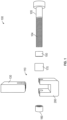
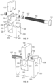
FIG. 1 is an exploded view of a system for shear testing a threaded section of a bolt according to an embodiment, including a fork, cutter block, sleeves and a bolt; -
FIG. 2 is a perspective view of the system; -
FIG. 3 is a detail of the embodiments identified inFIG. 2 , showing aspects of the fork and sleeves; -
FIG. 4 is an assembly view of the system, without showing the cutter block; -
FIG. 5 is a further detail of the embodiments identified inFIG. 2 , showing aspects of the cutter block; -
FIG. 6 is shows the testing of the bolt with the system; -
FIG. 7 shows additional components of the system in an exploded view; -
FIG. 8 shows the additional components of the system in an assembly view; and -
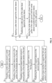
FIG. 9 is a flowchart showing a method of testing a threaded section of a bolt. - Turning to
FIGS. 1 and2 , asystem 100 is shown for double shear testing of a threadedsection 104 of a cylinder orbolt 105. Thesystem 100 includes ashear die set 110 having afork 120 and acutter block 130. Thesystem 100 includes first andsecond support sleeves bolt 105 are supported by thefork 120 as discussed below. Thesecond support sleeve 160 has a same size and shape as thefirst support sleeve 150. Acenter sleeve 170 that is radially lager than the first andsecond support sleeves bolt 105, between thesupport sleeves -
FIGS. 3 and 4 show thefork 120, the sleeves 150-170 and thebolt 105. Thefork 120 includes a fork-base 200 and afirst leg 210 extending from the fork-base 200 to a first end 220 (FIG. 3 ). Asecond leg 230 extends from the fork-base 200 to a second end 240 (FIG. 3 ). The first andsecond legs test cavity 250. - The
first leg 210 has afirst leg groove 260 formed into itsfirst end 220. Thefirst leg groove 260 may be defined by asemi-circular surface 265, and thefirst leg groove 260 may be smooth. Thesecond leg 230 has asecond leg groove 270 formed into itssecond end 240 that is aligned with thefirst leg groove 260 and has a same size and shape as thefirst leg groove 260. The first andsecond leg grooves second portions 280, 290 (FIG. 4 ) of the threadedsection 104 of the 105 bolt during a shear test. - The
center sleeve 170 has an axial length that corresponds with, e.g., is the same as, the first distance D1 to provide a slip fit between thecenter sleeve 170 and the first andsecond legs fork 120. Thecenter sleeve 170 is radially larger than thefirst leg groove 260. Thecenter sleeve 170 has an inner threadedsurface 310 and is configured to receive a center portion 320 (FIG. 4 ) of the threadedsection 104 of thebolt 105 during the shear test. Thefirst portion 280 of the threadedsection 104 of thebolt 105 is between thecenter portion 320 of the threadedsection 104 of thebolt 105 and ahead 106 of thebolt 105. With this configuration, thefirst support sleeve 150 and thecenter sleeve 170 are axially adjacent to each other during the shear test. Thesecond portion 290 of the threadedsection 104 of thebolt 105 is between thecenter portion 320 and theend 107 of thebolt 105. With this configuration, the second support sleeve 160 and thecenter sleeve 170 are adjacent to each other during the shear test. - The
first support sleeve 150 has an inner threadedsurface 325 and is configured to receive thefirst portion 280 of the threadedsection 104 of thebolt 105. Thesecond support sleeve 160 is configured to receive thesecond portion 290 of the threadedsection 104 of thebolt 105 during the shear test. - The
center sleeve 170 has anouter diameter surface 330 that is radially larger than thesemi-circular surface 265 of thefirst leg groove 260. Anouter diameter surface 340 of thefirst support sleeve 150 is radially smaller than theouter diameter surface 330 of thecenter sleeve 170. Theouter diameter surface 340 is sized to fit in thefirst leg groove 260 during the shear test. That is, thecenter sleeve 170 has an outer diameter that is oversized to allow for proper alignment of thesleeve 170 between the first andsecond legs leg grooves center sleeve 170 and thefirst support sleeve 150 are smooth. - It is to be appreciated that reference to the
center portion 320 of the threadedsection 104 of thebolt 105 is for convenience and not intended to require the shear test be applied to a point halfway along the threadedsection 104 of thebolt 105. Any location intermediate thehead 106 and theend 107 of thebolt 105 that can be threaded into thecenter sleeve 170, and is axially surrounded byportions support sleeves center portion 320 of thebolt 105. In addition, the oversized center portion/sleeve 170 aligns the shear plane with the interface of the twosleeves - Turning to
FIG. 5 , thecutter block 130 has a thickness that corresponds with, e.g., is equal to, the first distance D1 to provide a slip fit between thecutter block 130 and the first andsecond legs fork 120. Thecutter block 130 has acutter surface 400, that faces the fork-base 200 of thefork 120 when thecutter block 130 is used during a shear test. Thecutter surface 400 has acutter groove 410 that is sized to receive thecenter sleeve 170 during the shear test. Thecutter groove 410 may be smooth. Thecutter groove 410 has alinear channel portion 420 that extends away from thecutter surface 400 to asleeve seat portion 430. Thesleeve seat portion 430 of thecutter groove 410 has aninner diameter surface 440 that is sized to correspond with, e.g., is the same size as, theouter diameter surface 330 of thecenter sleeve 170. That is, thesleeve seat portion 430 has a semi-circular cross section. Thecutter groove 410 of thecutter block 130 receives thecenter sleeve 170 by moving thecenter sleeve 170 through thelinear channel portion 420 of thecutter groove 410 until thecenter sleeve 170 is positioned against thesleeve seat portion 430 of thecutter groove 410. Thecutter surface 400 has chamferededges cutter block 130 in thetest cavity 250 during a shear test. - Turning to
FIG. 6 , the disclosed embodiments impose a shear force on the specimen, e.g., thebolt 105, and reduces or prevents minimal bending forces from developing along the center portion 320 (FIG. 4 ) of thebolt 105 within thetest cavity 250. The embodiments provide for the double shear testing of the threadedsection 104 of thebolt 105 by the inclusion of theouter support sleeves bolt 105, and theoversized center sleeve 170. The sleeves 150-170 are threaded tubes and thecenter sleeve 170 is sized so its axial ends are on the planes of shear, which are aligned with first and secondinner surfaces second legs fork 120. Thecenter sleeve 170 does not contribute to carrying shear load for thebolt 105. Theoversized center sleeve 170 which allows for proper alignment of thesleeve 170 between the first andsecond legs cutter block 130 has theoversized cutter groove 410 that is sized to receive and seat thecenter sleeve 170. With the disclosed embodiments, threads of thebolt 105 are supported by theouter sleeves - Turning to
FIGS. 7 and 8 , thesystem 100 is a die assembly that also includes a base-member 500 that seats therein thefork 120. The base-member 500 has abase 510 andupstanding legs base 200, forklegs head 106 of thebolt 105 and theend 107 of thebolt 105 ingrooves grooves member legs grooves fork 120. The base-member 500 provides support while thecutter block 130 is applied during a double shear test. During this time, the sleeves 150-170 support thebolt 105 as indicated above, while the base-member 500 that help braces thefork 120 to prevent bending in thesystem 100. - Turning to
FIG. 9 , a flowchart shows a method of shear testing the threadedsection 104 of thebolt 105. As shown inblock 10, the method includes threading thecenter sleeve 170 around thecenter portion 320 of the threadedsection 104 of thebolt 105. As shown inblock 10A, the method includesblock 10A of threading thefirst support sleeve 150 around thefirst portion 280 of the threadedsection 104 of thebolt 105. As shown inblock 10B, the method includes threading thesecond support sleeve 160 around thesecond portion 290 of the threadedsection 104 of thebolt 105. - As shown in
block 20A, the method includes positioning thefirst support sleeve 150 in thefirst leg groove 260. As shown inblock 20B, themethod 270 includes positioning thesecond support sleeve 160 in thesecond leg groove 270. - As shown in
block 30, the method includes utilizing a base-member 500 to support thefork 120 and portions of thebolt 105 that extend beyond thefork 120. As shown inblock 40, the method includes applying thecutter block 130 against thecenter sleeve 170. As shown inblock 40A, applying thecutter block 130 includes positioning thecutter groove 410 of thecutter block 130 against thecenter sleeve 170. As shown in block 40A1, this includes moving thecenter sleeve 170 through thelinear channel portion 420 of thecutter groove 410 until thecenter sleeve 170 is positioned against thesleeve seat portion 430 of thecutter groove 410. - The embodiments allow for shear data to be generated for threaded
section 104 of thebolt 105 and other threaded fasteners, cylinders and specimen. This allows for the empirical validation and understanding of fasteners and threaded components, as well as for the improvement of material models that this data supports. This also allows for the understanding and realization through mechanical testing of the benefits of specialized processing techniques of fasteners that otherwise may be difficult to model. The embodiments may be applied to the development of testing specifications and quality controls around fasteners. For example, fasteners that include cold-rolled threads for strengthening effects can be testing in shear to measure the impact of the cold-rolled processing method. The centeroversized sleeve 170 of the embodiments allow for relatively easy alignment of the sleeves and result in more accurate shear test data. - The terminology used herein is for the purpose of describing particular embodiments only and is not intended to be limiting of the present disclosure. As used herein, the singular forms "a", "an" and "the" are intended to include the plural forms as well, unless the context clearly indicates otherwise. It will be further understood that the terms "comprises" and/or "comprising," when used in this specification, specify the presence of stated features, integers, steps, operations, elements, and/or components, but do not preclude the presence or addition of one or more other features, integers, steps, operations, element components, and/or groups thereof.
- Those of skill in the art will appreciate that various example embodiments are shown and described herein, each having certain features in the particular embodiments, but the present disclosure is not thus limited. Rather, the present disclosure can be modified to incorporate any number of variations, alterations, substitutions, combinations, sub-combinations, or equivalent arrangements not heretofore described, but which are commensurate with the scope of the present disclosure. Additionally, while various embodiments of the present disclosure have been described, it is to be understood that aspects of the present disclosure may include only some of the described embodiments. Accordingly, the present disclosure is not to be seen as limited by the foregoing description, but is only limited by the scope of the appended claims.
Claims (15)
- A system (100) comprising:
a shear die set (110) having a fork (120) that includes:a fork-base (200);a first leg (210) extending from the fork-base (200) to a first end (220);a second leg (230) extending from the fork-base (200) to a second end (240),wherein:the first and second legs (210, 230) are spaced apart from each other by a first distance (D1) to define a test cavity (250); andthe first leg (210) has a first leg groove (260), and the second leg (230) has a second leg groove (270) that is aligned with the first leg groove (260) and has a same size and shape as the first leg groove (260); anda center sleeve (170) having an axial length that corresponds with the first distance (D1) and is radially larger than the first leg groove (260), wherein the center sleeve (170) has an inner threaded surface (310) and is configured to receive a center portion (320) of the threaded section (104) of the bolt (105) during the shear test;a first support sleeve (150) having an inner threaded surface (325) that is configured to receive a first portion (280) of the threaded section (104) of the bolt (105), and the first support sleeve (150) has an outer diameter surface (340) that is sized to fit in the first leg groove (260) during the shear test; anda second support sleeve (160) having a same size and shape as the first support sleeve (150), wherein the second support sleeve (160) is configured to receive a second portion (290) of the threaded section (104) of the bolt (105) and fit in the second leg groove (270) during the shear test; andthe outer diameter surface (340) of the first support sleeve (150) is radially different than an outer diameter surface (330) of the center sleeve (170). - The system (100) of claim 1, wherein:the first leg groove (260) is defined by a semi-circular surface (265); andthe outer diameter surface (330) of the center sleeve (170) is radially larger than the semi-circular surface (265) of the first leg groove (260).
- The system (100) of claim 1 or 2, wherein:
the outer diameter surface (340) of the first support sleeve (150) is radially smaller than the outer diameter surface (330) of the center sleeve (170). - The system (100) of any of claims 1 to 3, comprising:
a cutter block (130) having a thickness that corresponds with the first distance (D 1), the cutter block (130) having a cutter surface (400) with a cutter groove (410) that is sized to receive the center sleeve (170) during the shear test. - The system (100) of claim 4, wherein:
the cutter groove (410) has a linear channel portion (420) and a sleeve seat portion (430), wherein the linear channel portion (420) extends away from the cutter surface (400) to the sleeve seat portion (430), optionally wherein the sleeve seat portion (430) of the cutter groove (410) has an inner diameter surface (440) that is sized to correspond with the outer diameter surface (330) of the center sleeve (170). - The system (100) of claim 4 or 5, wherein:
the first leg groove (260) and the cutter groove (410) comprise smooth surfaces. - The system (100) of any preceding claim, wherein:
the outer diameter surfaces (330, 340) of the center sleeve (170) and the first support sleeve (150) are smooth. - The system (100) of any preceding claim, including a base-member (500) that receives and supports the fork (120) and receives and portions of the bolt (105) that extend axially beyond the fork (120) during a shear test, optionally wherein the base-member (500) includes upstanding legs (520, 530) that include grooves (540, 550) for supporting portions of the bolt (105) that extend axially beyond the fork (120) during a shear test.
- A method of shear testing a threaded section (104) of a bolt (105), comprising:threading at least a center sleeve (170) around a center portion (320) of the threaded section (104) of the bolt (105);threading a first support sleeve (150) around a first portion (280) of the threaded section (104) of the bolt (105), the first portion (280) being located between the center portion (320) and a head (106) of the bolt (105), so that the first support sleeve (150) and the center sleeve (170) are adjacent to each other; andthreading a second support sleeve (160) around a second portion (290) of the threaded section (104) of the bolt (105), the second portion (290) being between the center portion (320) and end (107) of the bolt (105), so that the second support sleeve (160) and the center sleeve (170) are adjacent to each other;wherein an outer diameter surface (340) of the first support sleeve (150) is radially different than an outer diameter surface (330) of the center sleeve (170);positioning the first support sleeve (150) in a first leg groove (260) of a first leg (210) that extends from fork-base (200) of a fork (120) of a shear die set (110);positioning the second support sleeve (160) in a second leg groove (270) of a second leg (230) that extends from of the fork-base (200) of the fork (120), wherein the second leg groove (270) has a same size and shape as the first leg groove (260), the first and second legs (210, 230) are spaced apart by a first distance (D1) to define a test cavity (250), and the center sleeve (170) has an axial length that corresponds with the first distance (D1) and is radially larger than the first leg groove (260); andapplying a cutter block (130) against the center sleeve (170).
- The method of claim 9, including supporting the fork (120) and portions of the bolt (105) that extend axially beyond the fork (120) with a base-member (500).
- The method of claim 9 or 10, wherein applying the cutter block (130) includes positioning a cutter groove (410) of the cutter block (130) against the center sleeve (170), optionally wherein positioning the cutter groove (410) of the cutter block (130) against the center sleeve (170) includes moving the center sleeve (170) through a linear channel portion (420) of the cutter groove (410) until the center sleeve (170) is positioned against a sleeve seat portion (430) of the cutter groove (410).
- A system (100) for performing a double shear test of a threaded section (104) of a cylinder or bolt (105), comprising:a shear die set (110) having a fork (120) and a cutter block (130);first and second support sleeves (150, 160) that are configured to engage the threaded section (104) of the bolt (105), wherein the first and second support sleeves (150, 160) are supported by the fork (120) during the shear test;the second support sleeve (160) has a same size and shape as the first support sleeve (150);a center sleeve (170) that is radially lager than the first and second support sleeves (150, 160), wherein the center sleeve (170) is configured to engage the threaded section (104) of the bolt (105), between the first and second support sleeves (150, 160); andan outer diameter surface (340) of the first support sleeve (150) is radially different than an outer diameter surface (330) of the center sleeve (170).
- The system (100) of claim 12, wherein:
the fork (120) has first and second legs (210, 230) spaced apart from each other by a first distance (D1) and the center sleeve (170) has an axial length that corresponds with the first distance (D1) to provide a slip fit between the center sleeve (170) and the first and second legs (210, 230) of the fork (120). - The system (100) of claim 13, wherein:the cutter block (130) has a thickness that corresponds with the first distance (D1) to provide a slip fit between the cutter block (130) and the first and second legs (210, 230) of the fork (120);the cutter block (130) has a cutter surface (400), that faces a fork-base (200) of the fork (120) during the shear test;the cutter surface (400) has a cutter groove (410) that is sized to receive the center sleeve (170) during the shear test;the cutter groove (410) has a linear channel portion (420) that extends away from the cutter surface (400) to a sleeve seat portion (430);the sleeve seat portion (430) of the cutter groove (410) has an inner diameter surface (440) that is sized to correspond with the outer diameter surface (330) of the center sleeve (170); andin operation, the cutter groove (410) of the cutter block (130) receives the center sleeve (170) by moving the center sleeve (170) through the linear channel portion (420) of the cutter groove (410) until the center sleeve (170) is positioned against the sleeve seat portion (430) of the cutter groove (410), optionally wherein:the outer diameter surfaces (330, 340) of the first and second support sleeves (150, 160) and the center sleeve (170) are smooth and the cutter groove (410) is smooth; and/orthe sleeve seat portion (430) of the cutter groove (410) has a semi-circular cross section.
- The system (100) of any of claims 12 to 14, including a base-member (500) that supports the fork (120) and portions of the bolt (105) that extend axially beyond the fork (120).
Applications Claiming Priority (1)
| Application Number | Priority Date | Filing Date | Title |
|---|---|---|---|
| US18/167,453 US12416557B2 (en) | 2023-02-10 | 2023-02-10 | System and method for applying a shear test to a threaded section of a bolt |
Publications (1)
| Publication Number | Publication Date |
|---|---|
| EP4414684A1 true EP4414684A1 (en) | 2024-08-14 |
Family
ID=89900900
Family Applications (1)
| Application Number | Title | Priority Date | Filing Date |
|---|---|---|---|
| EP24157199.1A Pending EP4414684A1 (en) | 2023-02-10 | 2024-02-12 | System and method for applying a shear test to a threaded section of a bolt |
Country Status (2)
| Country | Link |
|---|---|
| US (2) | US12416557B2 (en) |
| EP (1) | EP4414684A1 (en) |
Citations (5)
| Publication number | Priority date | Publication date | Assignee | Title |
|---|---|---|---|---|
| CN203894124U (en) * | 2014-03-16 | 2014-10-22 | 西安科技大学 | Light anti-shear fatigue tester |
| CN105352793A (en) * | 2015-11-20 | 2016-02-24 | 沈阳黎明航空发动机(集团)有限责任公司 | Clamp for shear test of aerial metal material and application thereof |
| CN210863414U (en) * | 2019-10-25 | 2020-06-26 | 株洲中车时代电气股份有限公司 | Bolt shear test anchor clamps |
| CN114441290A (en) * | 2021-12-24 | 2022-05-06 | 河南航天精工制造有限公司 | Bolt high-temperature shear test device and shear assembly |
| CN217561197U (en) * | 2022-06-09 | 2022-10-11 | 北京首航科学技术开发有限公司 | Normal-temperature double-shear test tool |
Family Cites Families (5)
| Publication number | Priority date | Publication date | Assignee | Title |
|---|---|---|---|---|
| US11692574B2 (en) * | 2017-09-14 | 2023-07-04 | Centrix Inc. | Fastener system |
| CN107817172A (en) | 2017-09-18 | 2018-03-20 | 华南理工大学 | A kind of anti-eccentric loading clamp of double-shear experiment holds device and method |
| CN210513904U (en) | 2019-06-28 | 2020-05-12 | 芜湖航翼集成设备有限公司 | Aircraft high-strength bolt shear test anchor clamps |
| CN215767946U (en) | 2021-08-02 | 2022-02-08 | 昆明理工大学 | Bolt shear test anchor clamps |
| CN113804540A (en) * | 2021-09-26 | 2021-12-17 | 华东交通大学 | A jig for testing the shear properties of composite materials |
-
2023
- 2023-02-10 US US18/167,453 patent/US12416557B2/en active Active
-
2024
- 2024-02-12 EP EP24157199.1A patent/EP4414684A1/en active Pending
-
2025
- 2025-09-12 US US19/327,482 patent/US20260009709A1/en active Pending
Patent Citations (5)
| Publication number | Priority date | Publication date | Assignee | Title |
|---|---|---|---|---|
| CN203894124U (en) * | 2014-03-16 | 2014-10-22 | 西安科技大学 | Light anti-shear fatigue tester |
| CN105352793A (en) * | 2015-11-20 | 2016-02-24 | 沈阳黎明航空发动机(集团)有限责任公司 | Clamp for shear test of aerial metal material and application thereof |
| CN210863414U (en) * | 2019-10-25 | 2020-06-26 | 株洲中车时代电气股份有限公司 | Bolt shear test anchor clamps |
| CN114441290A (en) * | 2021-12-24 | 2022-05-06 | 河南航天精工制造有限公司 | Bolt high-temperature shear test device and shear assembly |
| CN217561197U (en) * | 2022-06-09 | 2022-10-11 | 北京首航科学技术开发有限公司 | Normal-temperature double-shear test tool |
Also Published As
| Publication number | Publication date |
|---|---|
| US12416557B2 (en) | 2025-09-16 |
| US20260009709A1 (en) | 2026-01-08 |
| US20240272054A1 (en) | 2024-08-15 |
Similar Documents
| Publication | Publication Date | Title |
|---|---|---|
| EP2514565B1 (en) | Calibrated clamping device | |
| Bortot et al. | The determination of flow stress of tubular material for hydroforming applications | |
| JPH07500773A (en) | Improved hole fatigue life | |
| US20220187175A1 (en) | Stretch flange crack evaluation method, metal sheet selection method, press die design method, component shape design method, and pressed component manufacturing method | |
| KR102354894B1 (en) | A method for estimating the hardness of cold-worked parts and a method for obtaining a hardness-equivalent plastic deformation curve of steel | |
| EP4414684A1 (en) | System and method for applying a shear test to a threaded section of a bolt | |
| Han et al. | Experimental and numerical exploration for the design of swift-constructed demountable blind bolts | |
| Bambach et al. | Tests of unstiffened plate elements under combined compression and bending | |
| JP3021834B2 (en) | Residual stress measurement method and apparatus | |
| EP2006659A1 (en) | Method and apparatus for measuring the elasticity of materials for lining vehicle components | |
| DE69727964T2 (en) | MEASURING APPARATUS FOR CHECKING THE LINEAR DIMENSION OF MECHANICAL PARTS AND RELATED MANUFACTURING METHOD | |
| CN113237739A (en) | Continuous tension and compression test fixture for measuring Baoxing behavior | |
| DE102014206963B4 (en) | Clamping device for a blind rivet and method for determining a setting force curve of a blind rivet | |
| CN105964848A (en) | Strengthening method for fillet part of crankshaft and stengthening device therefor | |
| CN112540012B (en) | A circumferential pure shear loading method and device for pipes | |
| CN111678776B (en) | Indirect stretching device for testing tensile strength of rock | |
| CN111289370B (en) | A solid concrete compressive strength testing device using a circular ring pulling method | |
| CN219212896U (en) | Clamp | |
| US20250271340A1 (en) | Fixtures and Methods for Testing Articles in Tension When Using Compression Loading | |
| Santos et al. | Towards standard benchmarks and reference data for validation and improvement of numerical simulation in sheet metal forming | |
| KR101723442B1 (en) | Fatigue testing apparatus | |
| KR101129895B1 (en) | Jig for link sample size marking | |
| US20120204631A1 (en) | Brake tools and related methods | |
| DE20314761U1 (en) | Mechanical material compression test fixture has C shaped clamp blocks on guide rods with test piece held in hydraulically clamped jaws | |
| JPS6229944Y2 (en) |
Legal Events
| Date | Code | Title | Description |
|---|---|---|---|
| PUAI | Public reference made under article 153(3) epc to a published international application that has entered the european phase |
Free format text: ORIGINAL CODE: 0009012 |
|
| STAA | Information on the status of an ep patent application or granted ep patent |
Free format text: STATUS: THE APPLICATION HAS BEEN PUBLISHED |
|
| AK | Designated contracting states |
Kind code of ref document: A1 Designated state(s): AL AT BE BG CH CY CZ DE DK EE ES FI FR GB GR HR HU IE IS IT LI LT LU LV MC ME MK MT NL NO PL PT RO RS SE SI SK SM TR |
|
| STAA | Information on the status of an ep patent application or granted ep patent |
Free format text: STATUS: REQUEST FOR EXAMINATION WAS MADE |
|
| 17P | Request for examination filed |
Effective date: 20250213 |