EP4414635A1 - Multifunctional quick freezing equipment - Google Patents
Multifunctional quick freezing equipment Download PDFInfo
- Publication number
- EP4414635A1 EP4414635A1 EP23020352.3A EP23020352A EP4414635A1 EP 4414635 A1 EP4414635 A1 EP 4414635A1 EP 23020352 A EP23020352 A EP 23020352A EP 4414635 A1 EP4414635 A1 EP 4414635A1
- Authority
- EP
- European Patent Office
- Prior art keywords
- liquid nitrogen
- freezing
- plant
- quick freezing
- room
- Prior art date
- Legal status (The legal status is an assumption and is not a legal conclusion. Google has not performed a legal analysis and makes no representation as to the accuracy of the status listed.)
- Granted
Links
Images



Classifications
-
- F—MECHANICAL ENGINEERING; LIGHTING; HEATING; WEAPONS; BLASTING
- F25—REFRIGERATION OR COOLING; COMBINED HEATING AND REFRIGERATION SYSTEMS; HEAT PUMP SYSTEMS; MANUFACTURE OR STORAGE OF ICE; LIQUEFACTION SOLIDIFICATION OF GASES
- F25D—REFRIGERATORS; COLD ROOMS; ICE-BOXES; COOLING OR FREEZING APPARATUS NOT OTHERWISE PROVIDED FOR
- F25D16/00—Devices using a combination of a cooling mode associated with refrigerating machinery with a cooling mode not associated with refrigerating machinery
-
- F—MECHANICAL ENGINEERING; LIGHTING; HEATING; WEAPONS; BLASTING
- F25—REFRIGERATION OR COOLING; COMBINED HEATING AND REFRIGERATION SYSTEMS; HEAT PUMP SYSTEMS; MANUFACTURE OR STORAGE OF ICE; LIQUEFACTION SOLIDIFICATION OF GASES
- F25D—REFRIGERATORS; COLD ROOMS; ICE-BOXES; COOLING OR FREEZING APPARATUS NOT OTHERWISE PROVIDED FOR
- F25D17/00—Arrangements for circulating cooling fluids; Arrangements for circulating gas, e.g. air, within refrigerated spaces
- F25D17/04—Arrangements for circulating cooling fluids; Arrangements for circulating gas, e.g. air, within refrigerated spaces for circulating air, e.g. by convection
- F25D17/06—Arrangements for circulating cooling fluids; Arrangements for circulating gas, e.g. air, within refrigerated spaces for circulating air, e.g. by convection by forced circulation
-
- A—HUMAN NECESSITIES
- A23—FOODS OR FOODSTUFFS; TREATMENT THEREOF, NOT COVERED BY OTHER CLASSES
- A23B—PRESERVATION OF FOODS, FOODSTUFFS OR NON-ALCOHOLIC BEVERAGES; CHEMICAL RIPENING OF FRUIT OR VEGETABLES
- A23B2/00—Preservation of foods or foodstuffs, in general
- A23B2/80—Freezing; Subsequent thawing; Cooling
- A23B2/85—Freezing; Subsequent thawing; Cooling with addition of or treatment with chemicals
- A23B2/88—Freezing; Subsequent thawing; Cooling with addition of or treatment with chemicals with direct contact between the food and the chemical, e.g. liquid N2 at cryogenic temperature
-
- F—MECHANICAL ENGINEERING; LIGHTING; HEATING; WEAPONS; BLASTING
- F25—REFRIGERATION OR COOLING; COMBINED HEATING AND REFRIGERATION SYSTEMS; HEAT PUMP SYSTEMS; MANUFACTURE OR STORAGE OF ICE; LIQUEFACTION SOLIDIFICATION OF GASES
- F25D—REFRIGERATORS; COLD ROOMS; ICE-BOXES; COOLING OR FREEZING APPARATUS NOT OTHERWISE PROVIDED FOR
- F25D11/00—Self-contained movable devices, e.g. domestic refrigerators
- F25D11/04—Self-contained movable devices, e.g. domestic refrigerators specially adapted for storing deep-frozen articles
-
- F—MECHANICAL ENGINEERING; LIGHTING; HEATING; WEAPONS; BLASTING
- F25—REFRIGERATION OR COOLING; COMBINED HEATING AND REFRIGERATION SYSTEMS; HEAT PUMP SYSTEMS; MANUFACTURE OR STORAGE OF ICE; LIQUEFACTION SOLIDIFICATION OF GASES
- F25D—REFRIGERATORS; COLD ROOMS; ICE-BOXES; COOLING OR FREEZING APPARATUS NOT OTHERWISE PROVIDED FOR
- F25D2400/00—General features of, or devices for refrigerators, cold rooms, ice-boxes, or for cooling or freezing apparatus not covered by any other subclass
- F25D2400/30—Quick freezing
Definitions
- This invention relates to a quick-freezing equipment, cabinet type, with discontinuous operation, using the method of freezing by contact with liquid nitrogen, in order to reduce the temperature of the products to the temperature of storage in a frozen state.
- Freezing as a method of preservation, increases the permissible storage time of food products by more than 5...50 times compared to preservation by refrigeration.
- the increase in long-lasting quality obtained by freezing is based on the effects of low temperatures of strongly slowing down or completely inhibiting the development of microorganisms, of reducing or stopping metabolic processes in the case of living products, and of reducing chemical and biochemical reactions.
- the usual freezing of products during which their average temperature drops below -10°C in a duration that does not allow the triggering of unwanted enzymatic and microbiological reactions, is characterized by the adoption of average linear freezing speeds of 0.1...0.5 cm/h and is used for products with large thicknesses, such as: meat in carcasses or blocks, butter or other fats packed in crates, etc.
- the main methods of freezing food products are:
- the cooled air freezing method is the most widespread due to the fact that most food products lend themselves to this type of preservation.
- the application of the cooled air freezing method requires the existence of a closed, thermal insulated space, an air-cooling aggregate and a system of distribution of cooled air over the products.
- the heat is taken from the products, by direct transfer, by the cooled surface.
- Surface cooling is achieved either with a vaporizing refrigerant or with an intermediate agent. Heat transfer is carried out in most cases exclusively by thermal conductivity.
- Freezing by contact with intermediate agents consists in cooling the product by contact with a cooled intermediate agent, such as for example an aqueous solution of propylene glycol, and it is generally suitable for hermetically packaged products.
- a cooled intermediate agent such as for example an aqueous solution of propylene glycol
- the method of freezing by contact with cryogenic agents consists in using the latent heat of vaporization at atmospheric pressure of some cryogenic liquids as well as the sensible heat that the formed vapours absorb by increasing their temperature from the very low level of vaporization to a level close to the temperature at which the product is frozen.
- the cryogenic agents used in this case are: liquid nitrogen, nitrogen oxide, carbon dioxide.
- Liquid nitrogen freezing equipment can be of discontinuous or continuous operation. Those with discontinuous operation are made in the form of cabinets or freezing cells with relatively small freezing capacities of 100...500 kg of products per hour and are based on liquid nitrogen purging, nitrogen gas cooling or a combination thereof. Those with continuous operation are made with linear moving belt or spiral belt and can be liquid nitrogen immersion, liquid nitrogen spray or nitrogen gas cooling.
- liquid nitrogen for the quick freezing of food is one of the most common applications of gases in the food industry, being carried out with the aim of maintaining the qualities of the product for as long as possible, both from an organoleptic and nutritional point of view, through the quick lowering of the temperature to values lower than -18°C inside the product, so as to inhibit the activity of microorganisms.
- liquid nitrogen which comes into direct contact with the food to be frozen.
- Nitrogen the main component of the atmosphere, is odourless, colourless, tasteless and inert, and has no harmful effect on food.
- liquid nitrogen is found at a temperature of -196°C, its main characteristic being the ability to absorb a large amount of heat even at lower temperature, allowing high refrigeration efficiencies and heat transfer coefficients far superior to mechanical systems.
- cryogenic freezing equipment produced by companies such as Linde (Germany), Praxair (USA), Octofrost (Sweden), Air Products (USA), Kelox (Spain), etc. are known. These are of the following types:
- cabinet-type quick freezing equipment with discontinuous operation is known in the state of the art, using the method of freezing by contact with liquid nitrogen, exclusively ( JPS5495060A , CN206073538U , CN207797488U ) or in combination with the classic method of freezing by mechanical vapour compression ( JPH08296938A , US2015027141A1 ), which, however, has the disadvantage of a relatively high liquid nitrogen consumption, either due to the use of an additional amount of liquid nitrogen introduced into a heat exchanger to cool the atmosphere in the quick-freezing room, or due to liquid nitrogen purging simultaneously with the mobilization of the vapour mixture through mechanical ventilation, which leads to the entrainment of liquid nitrogen particles that have not yet reached the surface of the products subject to quick freezing to take their heat and divert their trajectory towards the side walls of the enclosure, which attracts a low efficiency of the heat absorption process and the extension of the quick freezing period, either due to the lack of a high-performance management of automatic management of the freezing process that ensures an economy of liquid nitrogen and the
- the quick freezing process can be considered non-uniform, either due to non-uniform distribution of liquid nitrogen, as a result of using uncalibrated purging devices and not paying due attention to the shape and footprint of the purged liquid nitrogen jet, or due to non-homogeneous exposure of products to the cooling medium, as a result of insufficient methods and means of homogeneous mobilization of the cooling medium.
- the multifunctional quick freezing equipment solves this technical problem and removes the mentioned disadvantages by using a double thermal-insulated enclosure, made by joining some polyurethane thermal insulation panels, in the form of a construction made up of two enclosures separated by a common thermal-insulating wall, respectively the quick freezing room, provided with an access door equipped with a defrost heater accompanied by a temperature sensor and a proximity sensor, and the adjacent pre-cooling / temporary frozen storage room, provided with an access door equipped with a defrost heater, which communicates between them by means of a pipe that crosses the common wall, equipped with an exhaust valve, having the role of favouring the achievement of a slight overpressure in the quick freezing room in order to avoid the rapid evacuation to the adjacent room of nitrogen vapours that have not yet been used at maximum efficiency, they being further reused for the additional cooling of the adjacent room and the reduction of the thermal load of the classic refrigerating plant that serves it, subsequently, after "exhaustion", being evacuated outside the enclosure through a pipe that crosses the ceiling
- both the latent heat of vaporization at atmospheric pressure of liquid nitrogen is used by purging it directly on the surface of the products, resulting in vaporization with heat absorption during the phase change, and the sensible heat of the vapours through recirculation with heat absorption, first from the quick freezing room and then from the adjacent room, making optimal use of the refrigerating capacity of liquid nitrogen and leading to the achievement of reduced energy consumption as a result of reducing the thermal load of the classic refrigerating plant serving the adjacent pre-cooling / temporary frozen storage room.
- the multifunctional quick freezing equipment performs liquid nitrogen purging using several high-precision nozzles, having a flat distribution on the target surface and allows the homogenization of the exposure to the liquid nitrogen jets by driving in a continuous rotational movement the tray rack on which the products subject to quick freezing are positioned. In this sense, the uniformity of the quick-freezing process is improved.
- the multifunctional quick freezing equipment uses an automatic control algorithm of the quick freezing process that does not allow starting the mobilization of the atmosphere inside the quick freezing room by means of the mechanical ventilation plant comprising several extended shaft fan motors and as many discharge propellers, as long as the liquid nitrogen purging is active.
- the automatic management algorithm of the quick freezing process has implemented a procedure that allows it to pass as quickly as possible over the phase of maximum crystallization of the aqueous solution contained in the product, i.e.
- the multifunctional quick-freezing equipment consists of a support frame, a double insulated enclosure, a mechanical vapour ventilation plant, a liquid nitrogen supply plant, a mechanical vapour compression freezing refrigeration plant, a Dewar vessel with purge head and an automation plant.
- the multifunctional quick freezing equipment comprises a support frame ( F ), a double thermal insulated enclosure ( IE ), a tray rack ( TR ), a tray rack drive system ( DS ), a mechanical vapour ventilation plant ( MV ), a liquid nitrogen supply plant ( NS ), a mechanical vapour compression freezing refrigeration plant ( CP ), a Dewar vessel ( DV ) with purge head and respectively an automation plant ( AP ).
- the double thermal insulated enclosure ( IE ) is made by joining several polyurethane thermal insulation panels ( 1 ), in the form of a construction made up of two enclosures separated by a common thermal-insulating wall (4), respectively the quick freezing room ( 2 ) provided with an access door equipped with a defrost heater accompanied by a temperature sensor and a proximity sensor, and the adjacent pre-cooling / temporary frozen storage room ( 3 ), provided with an access door equipped with a defrost heater, which communicates between them by means of a pipe ( 5 ) that crosses the common wall ( 4 ), equipped with an exhaust valve ( 6 ), having the role of favouring the achievement of a slight overpressure in the quick freezing room ( 2 ) in order to avoid the rapid evacuation to the adjacent room ( 3 ) of nitrogen vapours that have not yet been used at maximum efficiency, they being further reused for the additional cooling of the adjacent room ( 3 ) and the reduction of the thermal load of the classic refrigerating plant ( CP ) that serves it, subsequently, after "ex
- tubular elements for the connection to the enclosure ( IE ) of the various external sub-assemblies and the limitation of the thermal bridges, tubular elements, not positioned, made of high-density polyethylene, having mechanical and thermal characteristics compatible with the cryogenic temperatures inside, are provided.
- the tray rack drive system ( DS ) comprises a speed reducer ( 12 ), as source of mechanical power, a shaft ( 13 ) for the transfer of rotational movement and torque, two tubular elements ( 15 ) and ( 16 ) for mechanical and thermal protection, assembled demountable in the passage hole made in the floor of the quick freezing room ( 2 ), by inserting them from the direction of each of the two opposite sides of the floor and fixing them on its surface using self-tapping screws, two wear bushings ( 14 ), made of PTFE, acting as a sliding bearing for the shaft ( 13 ), fixed in position using a shaft circlip, not positioned, a flange hub ( 17 ), assembled demountable on the shaft by means of a parallel wedge and axially fixed by means of a shaft circlip, not positioned, and a circular plate ( 18 ), assembled demountable on the hub ( 17 ) by means of a screw-nut assembly, which supports the tray rack ( TR ).
- a speed reducer 12
- a shaft 13
- the liquid nitrogen supply plant ( NS ) consists of several stainless steel pipes interconnected by means of appropriate fittings, not positioned, a solenoid valve ( SV ) specially intended for cryogenic applications, several nozzles ( 10 ) with flat distribution, mounted via adjustable angle coupling elements, not positioned, which allow the adjustment of the direction of the cooling agent purging on the target surface, a thermal insulation on the outside, made by means of polyurethane foam shells for cryogenic applications, cased on the outside with aluminium foil, not positioned and an interior thermal insulation made using a thermal-insulating material intended for refrigerating systems, not shown and not positioned.
- Liquid nitrogen purging through the nozzles ( 10 ) with high precision and flat distribution on the target surface leads to the improvement of the distribution of liquid nitrogen on the surface of the products, in terms of constant flow, as a measure of the volume of liquid nitrogen distributed in the unit of time, as well as in terms of the coefficient of variation of the liquid nitrogen volume distribution through the nozzles, as a measure of the homogeneous distribution of the liquid through all the nozzles.
- the automation plant ( AP ) comprises a thermocouple type temperature sensor ( TC1 ) for measuring the temperature in the centre of the product, a thermocouple type temperature sensor ( TC2 ) for measuring the temperature on the surface of the product, a temperature sensor ( PT100 ) thermoresistance type, for measuring the temperature in the freezing room, a 24 V DC power supply, a touchscreen operating terminal, a programmable logic controller ( PLC ) equipped with special modules for adapting signals from thermocouples, respectively thermoresistance, two bipolar fuses, a START-STOP button, an emergency stop button, several electromagnetic relays, a typified control panel, several gland-type power plugs and related electrical cables, not positioned.
- TC1 thermocouple type temperature sensor
- TC2 thermocouple type temperature sensor
- PT100 thermoresistance type
- PLC programmable logic controller
- the algorithm designed for the automatic management of the quick-freezing process does not allow the mobilization of the atmosphere inside the quick freezing room ( 2 ) to be started by means of the mechanical ventilation plant ( MV ), which comprises several extended shaft fan motors and as many discharge propellers, not positioned.
- the automatic management algorithm of the quick freezing process has implemented a procedure that allows it to pass as quickly as possible over the phase of maximum crystallization of the aqueous solution contained in the product, i.e.
- the food products are placed evenly on the trays inside the equipment, after which the temperature sensors are positioned as follows: the sensor for measuring the temperature in the centre of the product is inserted with its tip up to the thermal centre of a product; the sensor for measuring the temperature on the surface of the product is placed with the sensitive element on the external surface of a product, without being in contact with the walls of the enclosure or the trays inside.
- Close the access door watch the door closed indicator and set the process parameters (limit temperature in the room and limit temperature inside the product) in the automatic working mode, using the touch screen of the command and control panel.
- the product status indicator that signals the end of the freeze cycle is followed.
- the liquid nitrogen vaporizes, it expands in the quick-freezing room and upon reaching a slight overpressure, it will be discharged inside the frozen storage room.
- the equipment ensures the superior recovery of the "exhausted" refrigerant, by reusing the cold nitrogen vapours (e.g. -30°C on average, but varies according to the parameters set for the work process) discharged from the quick-freezing room.
- press the STOP button close the liquid nitrogen purge valve, switch to manual mode and press the solenoid valve opening button to release the possible volume of liquid nitrogen or vapour remaining on the section between the purge valve and the solenoid valve.
Landscapes
- Engineering & Computer Science (AREA)
- Chemical & Material Sciences (AREA)
- Combustion & Propulsion (AREA)
- Physics & Mathematics (AREA)
- Mechanical Engineering (AREA)
- Thermal Sciences (AREA)
- General Engineering & Computer Science (AREA)
Abstract
Description
- This invention relates to a quick-freezing equipment, cabinet type, with discontinuous operation, using the method of freezing by contact with liquid nitrogen, in order to reduce the temperature of the products to the temperature of storage in a frozen state.
- Use of artificial cold within the two classic methods of preservation by refrigeration and freezing, offers the guarantee of preserving the taste as close as possible to the original of perishable food products, unlike other preservation methods.
- Freezing, as a method of preservation, increases the permissible storage time of food products by more than 5...50 times compared to preservation by refrigeration. The increase in long-lasting quality obtained by freezing is based on the effects of low temperatures of strongly slowing down or completely inhibiting the development of microorganisms, of reducing or stopping metabolic processes in the case of living products, and of reducing chemical and biochemical reactions.
- According to the average linear freezing rate, Wm, the International Institute of Refrigeration (Institut International du Froid - IIF) recommends the following classification of freezing methods:
- slow freezing Wm = 0.5 cm/h; - quick freezing Wm = 0.5...3 cm/h; - very quick-freezing Wm = 3...10 cm/h; - ultra-quick-freezing Wm = 10...100 cm/h. - The usual freezing of products, during which their average temperature drops below -10°C in a duration that does not allow the triggering of unwanted enzymatic and microbiological reactions, is characterized by the adoption of average linear freezing speeds of 0.1...0.5 cm/h and is used for products with large thicknesses, such as: meat in carcasses or blocks, butter or other fats packed in crates, etc.
- Quick-frozen products are obtained at average linear freezing speeds greater than 0.5 cm/h.
- The main methods of freezing food products are:
- cooled air freezing;
- freezing by contact with cold metal surfaces;
- freezing by contact with intermediate agents;
- freezing with cryogenic agents.
- The cooled air freezing method is the most widespread due to the fact that most food products lend themselves to this type of preservation. In general, the application of the cooled air freezing method requires the existence of a closed, thermal insulated space, an air-cooling aggregate and a system of distribution of cooled air over the products.
- In the case of freezing by contact with metal surfaces, the heat is taken from the products, by direct transfer, by the cooled surface. Surface cooling is achieved either with a vaporizing refrigerant or with an intermediate agent. Heat transfer is carried out in most cases exclusively by thermal conductivity.
- Freezing by contact with intermediate agents consists in cooling the product by contact with a cooled intermediate agent, such as for example an aqueous solution of propylene glycol, and it is generally suitable for hermetically packaged products.
- The method of freezing by contact with cryogenic agents consists in using the latent heat of vaporization at atmospheric pressure of some cryogenic liquids as well as the sensible heat that the formed vapours absorb by increasing their temperature from the very low level of vaporization to a level close to the temperature at which the product is frozen. The cryogenic agents used in this case are: liquid nitrogen, nitrogen oxide, carbon dioxide.
- Liquid nitrogen freezing equipment can be of discontinuous or continuous operation. Those with discontinuous operation are made in the form of cabinets or freezing cells with relatively small freezing capacities of 100...500 kg of products per hour and are based on liquid nitrogen purging, nitrogen gas cooling or a combination thereof. Those with continuous operation are made with linear moving belt or spiral belt and can be liquid nitrogen immersion, liquid nitrogen spray or nitrogen gas cooling.
- The use of liquid nitrogen for the quick freezing of food is one of the most common applications of gases in the food industry, being carried out with the aim of maintaining the qualities of the product for as long as possible, both from an organoleptic and nutritional point of view, through the quick lowering of the temperature to values lower than -18°C inside the product, so as to inhibit the activity of microorganisms.
- If the decrease in temperature is achieved slowly, a progressive formation of small and large ice crystals is obtained, which can destroy the cellular structure of the product and irreparably destroy the tissues upon defrosting. If, on the contrary, these temperatures are reached quickly, crystallization can be avoided by creating an amorphous phase that favours the stability of the products during the following storage period.
- The fastest method for cooling food products is to use liquid nitrogen, which comes into direct contact with the food to be frozen. Nitrogen, the main component of the atmosphere, is odourless, colourless, tasteless and inert, and has no harmful effect on food. At atmospheric pressure, liquid nitrogen is found at a temperature of -196°C, its main characteristic being the ability to absorb a large amount of heat even at lower temperature, allowing high refrigeration efficiencies and heat transfer coefficients far superior to mechanical systems.
- In the case of nitrogen, 48% of the total refrigerating capacity is represented by latent heat of phase change, and the remaining 52% is represented by the sensible heat of the vapours, which, for this reason, are recirculated in the freezing room in order to make maximum use of cooling capacity.
- Freezing with liquid nitrogen allows:
- reduction of dehydration losses below 0.5% of the product weight;
- avoiding the destruction of the cellular and superficial structure of food;
- keeping the superficial aspect unaltered;
- carrying out freezing and storage operations in the absence of oxygen;
- significantly reducing the investment costs of production facilities.
- In the state of the art, cryogenic freezing equipment produced by companies such as Linde (Germany), Praxair (USA), Octofrost (Sweden), Air Products (USA), Kelox (Spain), etc. are known. These are of the following types:
- Cryogenic cabinet: is equipment designed for discontinuous operations and intended for users whose production needs do not justify the installation of continuous operation equipment. The product must be placed in trays positioned on a stainless-steel rack. An automated system regulates the introduction of nitrogen, depending on the temperature and duration of the desired cycles.
- Linear tunnel: consists of an insulated room in which the product is introduced with the help of a stainless-steel conveyor belt. In the pre-cooling zone, the product is covered in countercurrent, by a cold flow of nitrogen gas; in the middle zone, a first superficial freezing takes place where a partial contact occurs between the product and the liquid nitrogen which, through vaporization, takes the heat of the product causing its quick freezing. In the last zone, the temperature of the product is homogenized, being brought to the desired value in the centre of the product. The tunnel is equipped with an automated system that regulates the introduction of cryogenic fluid, so as to maintain a regulated temperature inside. In addition, a conveyor belt speed control system and a series of homogenizing fans and exhaust gas extractors are provided.
- Spiral freezer: is a compact equipment that allows obtaining very high production capacities occupying an extremely small space. It consists of an insulated room, in which the product is introduced by means of a loop conveyor belt, made of stainless steel, which moves in a spiral. Liquid nitrogen is introduced at the top where, by vaporization, it creates a quick-freezing zone. With the help of a ventilation system, cold gases are directed to the bottom, where they pre-cool the incoming product. The spiral freezer is equipped with an automated system for regulating the temperature and speed of the conveyor belt.
- Immersion tunnel: is the ideal system if the available space is limited, when a very quick freezing is required or a superficial crust is desired. The product is introduced into the tunnel using a stainless-steel conveyor belt and passes through the liquid nitrogen bath. In this way, the surface crust is formed instantly, while freezing inside requires very short times.
- Thus, cabinet-type quick freezing equipment with discontinuous operation is known in the state of the art, using the method of freezing by contact with liquid nitrogen, exclusively (
JPS5495060A CN206073538U ,CN207797488U ) or in combination with the classic method of freezing by mechanical vapour compression (JPH08296938A US2015027141A1 ), which, however, has the disadvantage of a relatively high liquid nitrogen consumption, either due to the use of an additional amount of liquid nitrogen introduced into a heat exchanger to cool the atmosphere in the quick-freezing room, or due to liquid nitrogen purging simultaneously with the mobilization of the vapour mixture through mechanical ventilation, which leads to the entrainment of liquid nitrogen particles that have not yet reached the surface of the products subject to quick freezing to take their heat and divert their trajectory towards the side walls of the enclosure, which attracts a low efficiency of the heat absorption process and the extension of the quick freezing period, either due to the lack of a high-performance management of automatic management of the freezing process that ensures an economy of liquid nitrogen and the optimal utilization of its refrigerating capacity. - After the liquid nitrogen pre-cooling phase, to maintain the products at the freezing temperature until the temperature is uniform and the quick-freezing cycle is completed, a classic mechanical vapour compression freezing plant is used, which leads to additional energy consumption. Also, the quick freezing process can be considered non-uniform, either due to non-uniform distribution of liquid nitrogen, as a result of using uncalibrated purging devices and not paying due attention to the shape and footprint of the purged liquid nitrogen jet, or due to non-homogeneous exposure of products to the cooling medium, as a result of insufficient methods and means of homogeneous mobilization of the cooling medium.
- Technical problem, solved by the invention, consists in the creation of a quick freezing equipment, cabinet type, with discontinuous operation, using the method of freezing by contact with liquid nitrogen, which ensures a low consumption of liquid nitrogen, allows the optimal utilization of its refrigerating capacity, ensures low energy consumption, improves the uniformity of the quick freezing process and increases the quality of quick frozen products.
- The multifunctional quick freezing equipment, according to the invention, solves this technical problem and removes the mentioned disadvantages by using a double thermal-insulated enclosure, made by joining some polyurethane thermal insulation panels, in the form of a construction made up of two enclosures separated by a common thermal-insulating wall, respectively the quick freezing room, provided with an access door equipped with a defrost heater accompanied by a temperature sensor and a proximity sensor, and the adjacent pre-cooling / temporary frozen storage room, provided with an access door equipped with a defrost heater, which communicates between them by means of a pipe that crosses the common wall, equipped with an exhaust valve, having the role of favouring the achievement of a slight overpressure in the quick freezing room in order to avoid the rapid evacuation to the adjacent room of nitrogen vapours that have not yet been used at maximum efficiency, they being further reused for the additional cooling of the adjacent room and the reduction of the thermal load of the classic refrigerating plant that serves it, subsequently, after "exhaustion", being evacuated outside the enclosure through a pipe that crosses the ceiling of the adjacent room, equipped with an exhaust valve. In this sense, both the latent heat of vaporization at atmospheric pressure of liquid nitrogen is used by purging it directly on the surface of the products, resulting in vaporization with heat absorption during the phase change, and the sensible heat of the vapours through recirculation with heat absorption, first from the quick freezing room and then from the adjacent room, making optimal use of the refrigerating capacity of liquid nitrogen and leading to the achievement of reduced energy consumption as a result of reducing the thermal load of the classic refrigerating plant serving the adjacent pre-cooling / temporary frozen storage room.
- Also, the multifunctional quick freezing equipment, according to the invention, performs liquid nitrogen purging using several high-precision nozzles, having a flat distribution on the target surface and allows the homogenization of the exposure to the liquid nitrogen jets by driving in a continuous rotational movement the tray rack on which the products subject to quick freezing are positioned. In this sense, the uniformity of the quick-freezing process is improved.
- At the same time, the multifunctional quick freezing equipment, according to the invention, uses an automatic control algorithm of the quick freezing process that does not allow starting the mobilization of the atmosphere inside the quick freezing room by means of the mechanical ventilation plant comprising several extended shaft fan motors and as many discharge propellers, as long as the liquid nitrogen purging is active. In this sense, by avoiding the entrainment of liquid nitrogen particles and the deviation of their trajectory towards the side walls of the enclosure, an increased efficiency of the heat absorption process and a reduction of the quick-freezing period are obtained, which leads to a reduced consumption of liquid nitrogen. Also, the automatic management algorithm of the quick freezing process has implemented a procedure that allows it to pass as quickly as possible over the phase of maximum crystallization of the aqueous solution contained in the product, i.e. as long as the temperature measured in the centre of the product is within the range of -2°C...-5°C, continuous purging of liquid nitrogen will be allowed regardless of the limitation established for the temperature of the atmosphere inside the quick freezing room. Thus, the formation of numerous small-sized ice crystals is ensured, which insignificantly degrade the structure of tissues and cell membranes, with a reduced loss of cell juice during defrosting, leading to an increase in the quality of quick-frozen products.
- The multifunctional quick-freezing equipment consists of a support frame, a double insulated enclosure, a mechanical vapour ventilation plant, a liquid nitrogen supply plant, a mechanical vapour compression freezing refrigeration plant, a Dewar vessel with purge head and an automation plant.
- The multifunctional quick-freezing equipment has the following advantages:
- optimally exploits the refrigerating capacity of liquid nitrogen due to the use of both the latent heat of vaporization at atmospheric pressure of liquid nitrogen and the sensible heat of the vapours;
- reduces energy consumption as a result of the reuse of cold nitrogen vapours to reduce the thermal load of the classic refrigerating plant that serves the adjacent pre-cooling / temporary frozen storage room;
- improves the uniformity of the quick-freezing process due to the homogenization of the exposure to liquid nitrogen jets and the improvement of its distribution;
- reduces the consumption of liquid nitrogen as a result of the implementation of an automatic management algorithm of the work process, which does not allow liquid nitrogen to be purged simultaneously with the mobilization of the atmosphere inside the quick-freezing room;
- increases the quality of frozen products quickly due to the implementation within the algorithm of the work process automatic management, a procedure that allows it to pass as quickly as possible over the phase of maximum crystallization of the aqueous solution contained in the product.
- An embodiment of the invention is shown below also in connection with
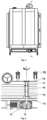
Figures 1-7 , which represent: - - Fig.1
- - Multifunctional quick-freezing equipment - main view;
- - Fig.2
- - Sectional route A-A - top view;
- - Fig.3
- - Multifunctional quick-freezing equipment - section in steps following sectional route A-A;
- - Fig.4
- - Sectional route B-B - lateral view-left;
- - Fig.5
- - Detail of the tray rack drive system - vertical section following sectional route B-B;
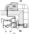
- - Fig.6
- - Detail of liquid nitrogen supply plant - vertical section following sectional route B-B;
- - Fig.7
- - Automation plant - General diagram of power supply and control.
- The multifunctional quick freezing equipment, according to the invention, comprises a support frame (F), a double thermal insulated enclosure (IE), a tray rack (TR), a tray rack drive system (DS), a mechanical vapour ventilation plant (MV), a liquid nitrogen supply plant (NS), a mechanical vapour compression freezing refrigeration plant (CP), a Dewar vessel (DV) with purge head and respectively an automation plant (AP).
- The double thermal insulated enclosure (IE) is made by joining several polyurethane thermal insulation panels (1), in the form of a construction made up of two enclosures separated by a common thermal-insulating wall (4), respectively the quick freezing room (2) provided with an access door equipped with a defrost heater accompanied by a temperature sensor and a proximity sensor, and the adjacent pre-cooling / temporary frozen storage room (3), provided with an access door equipped with a defrost heater, which communicates between them by means of a pipe (5) that crosses the common wall (4), equipped with an exhaust valve (6), having the role of favouring the achievement of a slight overpressure in the quick freezing room (2) in order to avoid the rapid evacuation to the adjacent room (3) of nitrogen vapours that have not yet been used at maximum efficiency, they being further reused for the additional cooling of the adjacent room (3) and the reduction of the thermal load of the classic refrigerating plant (CP) that serves it, subsequently, after "exhaustion", being evacuated outside the enclosure (IE) through a pipe (8) that crosses the ceiling (7) of the adjacent room (3), equipped with an exhaust valve (9). For the connection to the enclosure (IE) of the various external sub-assemblies and the limitation of the thermal bridges, tubular elements, not positioned, made of high-density polyethylene, having mechanical and thermal characteristics compatible with the cryogenic temperatures inside, are provided.
- The tray rack drive system (DS) comprises a speed reducer (12), as source of mechanical power, a shaft (13) for the transfer of rotational movement and torque, two tubular elements (15) and (16) for mechanical and thermal protection, assembled demountable in the passage hole made in the floor of the quick freezing room (2), by inserting them from the direction of each of the two opposite sides of the floor and fixing them on its surface using self-tapping screws, two wear bushings (14), made of PTFE, acting as a sliding bearing for the shaft (13), fixed in position using a shaft circlip, not positioned, a flange hub (17), assembled demountable on the shaft by means of a parallel wedge and axially fixed by means of a shaft circlip, not positioned, and a circular plate (18), assembled demountable on the hub (17) by means of a screw-nut assembly, which supports the tray rack (TR).
- The liquid nitrogen supply plant (NS) consists of several stainless steel pipes interconnected by means of appropriate fittings, not positioned, a solenoid valve (SV) specially intended for cryogenic applications, several nozzles (10) with flat distribution, mounted via adjustable angle coupling elements, not positioned, which allow the adjustment of the direction of the cooling agent purging on the target surface, a thermal insulation on the outside, made by means of polyurethane foam shells for cryogenic applications, cased on the outside with aluminium foil, not positioned and an interior thermal insulation made using a thermal-insulating material intended for refrigerating systems, not shown and not positioned. Liquid nitrogen purging through the nozzles (10) with high precision and flat distribution on the target surface, leads to the improvement of the distribution of liquid nitrogen on the surface of the products, in terms of constant flow, as a measure of the volume of liquid nitrogen distributed in the unit of time, as well as in terms of the coefficient of variation of the liquid nitrogen volume distribution through the nozzles, as a measure of the homogeneous distribution of the liquid through all the nozzles.
- Driving in a continuous rotation movement of the tray rack (TR) on which the products subject to quick freezing are positioned, in conjunction with the use of nozzles (10) with flat distribution on the target surface leads to the homogenization of the exposure to the liquid nitrogen jets, in terms of coverage degree of the external surfaces of the products.
- The automation plant (AP) comprises a thermocouple type temperature sensor (TC1) for measuring the temperature in the centre of the product, a thermocouple type temperature sensor (TC2) for measuring the temperature on the surface of the product, a temperature sensor (PT100) thermoresistance type, for measuring the temperature in the freezing room, a 24 V DC power supply, a touchscreen operating terminal, a programmable logic controller (PLC) equipped with special modules for adapting signals from thermocouples, respectively thermoresistance, two bipolar fuses, a START-STOP button, an emergency stop button, several electromagnetic relays, a typified control panel, several gland-type power plugs and related electrical cables, not positioned.
- As long as the liquid nitrogen purging is active, the algorithm designed for the automatic management of the quick-freezing process does not allow the mobilization of the atmosphere inside the quick freezing room (2) to be started by means of the mechanical ventilation plant (MV), which comprises several extended shaft fan motors and as many discharge propellers, not positioned. Also, the automatic management algorithm of the quick freezing process has implemented a procedure that allows it to pass as quickly as possible over the phase of maximum crystallization of the aqueous solution contained in the product, i.e. as long as the temperature measured in the centre of the product by means of the sensor (TC1) is within the range -2°C...-5°C, the continuous purging of liquid nitrogen will be allowed regardless of the limitation established for the temperature of the atmosphere inside the quick freezing room (2) measured by means of the sensor (PT100). Thus, numerous small-sized ice crystals are formed, which insignificantly degrade the structure of tissues and cell membranes, with a reduced loss of cell juice during defrosting, leading to an increase in the quality of quick-frozen products.
- The food products (whole or chopped) are placed evenly on the trays inside the equipment, after which the temperature sensors are positioned as follows: the sensor for measuring the temperature in the centre of the product is inserted with its tip up to the thermal centre of a product; the sensor for measuring the temperature on the surface of the product is placed with the sensitive element on the external surface of a product, without being in contact with the walls of the enclosure or the trays inside. Close the access door, watch the door closed indicator and set the process parameters (limit temperature in the room and limit temperature inside the product) in the automatic working mode, using the touch screen of the command and control panel. Next, slowly open the liquid nitrogen purge valve to the end of the stroke, after which the START button on the command and control panel is actuated. The product status indicator that signals the end of the freeze cycle is followed. As the liquid nitrogen vaporizes, it expands in the quick-freezing room and upon reaching a slight overpressure, it will be discharged inside the frozen storage room. In this way, the equipment ensures the superior recovery of the "exhausted" refrigerant, by reusing the cold nitrogen vapours (e.g. -30°C on average, but varies according to the parameters set for the work process) discharged from the quick-freezing room. At the end of the quick-freezing cycle, press the STOP button, close the liquid nitrogen purge valve, switch to manual mode and press the solenoid valve opening button to release the possible volume of liquid nitrogen or vapour remaining on the section between the purge valve and the solenoid valve. The closing of the solenoid valve is actuated, after which the access door is opened, the sensors are removed from within/from the products wearing gloves with adequate thermal protection, the products are removed from the trays and the door is closed. Quick-frozen products will be able to be kept frozen inside the second thermal insulated enclosure equipped with mechanical vapour compression freezing refrigeration plant, the effect of which will be improved with the help of vapours "exhausted" during the quick-freezing cycle.
Claims (4)
- Multifunctional quick freezing equipment that comprises a support frame (S), a mechanical vapour ventilation plant (MV), a mechanical vapour compression freezing refrigeration plant (CP), a tray rack (TR), a Dewar vessel (DV) with purge head, characterized by the fact that it contains a double thermal insulated enclosure (IE), made by joining several polyurethane thermal insulation panels (1), in the form of a construction made up of two enclosures separated by a common thermal-insulating wall (4), respectively a quick freezing room (2) provided with an access door equipped with a defrost heater accompanied by a temperature sensor and a proximity sensor, and an adjacent pre-cooling / temporary frozen storage room (3), provided with an access door equipped with a defrost heater, which communicates between them by means of a pipe (5) that crosses a common wall (4), equipped with an exhaust valve (6), having the role of favouring the achievement of a slight overpressure in the quick freezing room (2) in order to avoid the rapid evacuation to the adjacent room (3) of nitrogen vapours that have not yet been used at maximum efficiency, they being further reused for the additional cooling of the adjacent room (3) and the reduction of the thermal load of the classic refrigerating plant (CP) that serves it, subsequently, after "exhaustion", being evacuated outside an enclosure (IE) through a pipe (8) that crosses a ceiling (7) of the adjacent room (3), equipped with an exhaust valve (9), a tray rack drive system (DS) and a liquid nitrogen supply plant (NS) configured to, through a synergistic action, purge liquid nitrogen with high precision and flat distribution on the target surface and to homogenize the exposure to the liquid nitrogen jets, and respectively an automation plant (AP) configured both to avoid the entrainment of liquid nitrogen particles and the deviation of their trajectory towards the side walls of the enclosure, and to quickly pass the phase of maximum crystallization of the aqueous solution contained in the product.
- Multifunctional quick freezing equipment, according to claim 1, characterized by the fact that, the tray rack drive system (DS) comprises a speed reducer (12), as source of mechanical power, a shaft (13) for the transfer of rotational movement and torque, two tubular elements (15) and (16) for mechanical and thermal protection, assembled demountable in the passage hole made in the floor of the quick freezing room (2), by inserting them from the direction of each of the two opposite sides of the floor and fixing them on its surface using self-tapping screws, two wear bushings (14), made of PTFE, acting as a sliding bearing for the shaft (13), fixed in position using a shaft circlip, not positioned, a flange hub (17), assembled demountable on the shaft by means of a parallel wedge and axially fixed by means of a shaft circlip, not positioned, and a circular plate (18), assembled demountable on the hub (17) by means of a screw-nut assembly, which supports the tray rack (TR).
- Multifunctional quick freezing equipment, according to claim 1, characterized by the fact that, the liquid nitrogen supply plant (NS) consists of several stainless steel pipes interconnected by means of appropriate fittings, not positioned, a solenoid valve (SV) specially intended for cryogenic applications, several nozzles (10) with flat distribution, mounted via adjustable angle coupling elements, not positioned, which allow the adjustment of the direction of the cooling agent purging on the target surface, a thermal insulation on the outside, made by means of polyurethane foam shells for cryogenic applications, cased on the outside with aluminium foil, not positioned and an interior thermal insulation made using a thermal-insulating material intended for refrigerating systems.
- Multifunctional quick freezing equipment, according to claim 1, characterized by the fact that, the automation plant (AP) comprises a thermocouple type temperature sensor (TC1) for measuring the temperature in the centre of the product, a thermocouple type temperature sensor (TC2) for measuring the temperature on the surface of the product, a temperature sensor (PT100) of thermoresistance type, for measuring the temperature in the freezing room, a 24 V DC power supply, a touchscreen operating terminal, a programmable logic controller (PLC) equipped with special modules for adapting signals from thermocouples, respectively thermoresistance, two bipolar fuses, a START-STOP button, an emergency stop button, several electromagnetic relays, a typified control panel, several gland-type power plugs and related electrical cables, not positioned, and is configured so that the algorithm designed for the automatic management of the quick freezing process does not allow the mobilization of the atmosphere inside the quick freezing room (2) to be started by means of the mechanical ventilation plant (MV), which comprises several extended shaft fan motors and as many discharge propellers, not positioned, as long as the purging of liquid nitrogen is active and the passage over the phase of maximum crystallization of the aqueous solution contained in the product takes place as quickly as possible, so that as long as the temperature measured in the centre of the product by means of the sensor (TC1) is within the range -2°C...-5°C, the continuous purging of liquid nitrogen will be allowed regardless of the limitation established for the temperature of the atmosphere inside the quick freezing room (2) measured by means of the sensor (PT100).
Applications Claiming Priority (1)
| Application Number | Priority Date | Filing Date | Title |
|---|---|---|---|
| ROA202300054A RO138346A2 (en) | 2023-02-07 | 2023-02-07 | Fast freezing multipurpose equipment |
Publications (2)
| Publication Number | Publication Date |
|---|---|
| EP4414635A1 true EP4414635A1 (en) | 2024-08-14 |
| EP4414635B1 EP4414635B1 (en) | 2025-07-09 |
Family
ID=87748276
Family Applications (1)
| Application Number | Title | Priority Date | Filing Date |
|---|---|---|---|
| EP23020352.3A Active EP4414635B1 (en) | 2023-02-07 | 2023-07-25 | Multifunctional quick freezing equipment |
Country Status (2)
| Country | Link |
|---|---|
| EP (1) | EP4414635B1 (en) |
| RO (1) | RO138346A2 (en) |
Cited By (1)
| Publication number | Priority date | Publication date | Assignee | Title |
|---|---|---|---|---|
| CN121557659A (en) * | 2026-01-22 | 2026-02-24 | 福建技术师范学院 | By-product partition refrigeration device and refrigeration method for abalone flavor peptide enzymolysis extraction |
Citations (8)
| Publication number | Priority date | Publication date | Assignee | Title |
|---|---|---|---|---|
| GB1461617A (en) * | 1974-04-05 | 1977-01-13 | Kueleg Kuehlmoebelfabrik Appar | Refrigeration apparatus |
| JPH08338678A (en) * | 1995-06-14 | 1996-12-24 | Liquid Gas:Kk | Refrigerating equipment |
| KR20050081728A (en) * | 2004-02-16 | 2005-08-19 | 최미애 | Prefabricated reach-in refrigerator at home using |
| EP2765374A1 (en) * | 2013-02-07 | 2014-08-13 | Miele & Cie. KG | Domestic appliance and method for the automated opening at least one door of this household appliance |
| US20150027141A1 (en) | 2013-07-29 | 2015-01-29 | Louis Lilakos | Batch freezer with cryogenic precooling apparatus and method |
| CN206073538U (en) | 2016-08-25 | 2017-04-05 | 深圳市德捷力冷冻科技有限公司 | Liquid nitrogen cabinet type instant freezer |
| CN207797488U (en) | 2017-12-29 | 2018-08-31 | 深圳市瑞雪制冷设备有限公司 | Novel cabinet type instant freezer |
| CN115077166A (en) * | 2021-03-15 | 2022-09-20 | 海信容声(广东)冰箱有限公司 | refrigerator |
-
2023
- 2023-02-07 RO ROA202300054A patent/RO138346A2/en unknown
- 2023-07-25 EP EP23020352.3A patent/EP4414635B1/en active Active
Patent Citations (8)
| Publication number | Priority date | Publication date | Assignee | Title |
|---|---|---|---|---|
| GB1461617A (en) * | 1974-04-05 | 1977-01-13 | Kueleg Kuehlmoebelfabrik Appar | Refrigeration apparatus |
| JPH08338678A (en) * | 1995-06-14 | 1996-12-24 | Liquid Gas:Kk | Refrigerating equipment |
| KR20050081728A (en) * | 2004-02-16 | 2005-08-19 | 최미애 | Prefabricated reach-in refrigerator at home using |
| EP2765374A1 (en) * | 2013-02-07 | 2014-08-13 | Miele & Cie. KG | Domestic appliance and method for the automated opening at least one door of this household appliance |
| US20150027141A1 (en) | 2013-07-29 | 2015-01-29 | Louis Lilakos | Batch freezer with cryogenic precooling apparatus and method |
| CN206073538U (en) | 2016-08-25 | 2017-04-05 | 深圳市德捷力冷冻科技有限公司 | Liquid nitrogen cabinet type instant freezer |
| CN207797488U (en) | 2017-12-29 | 2018-08-31 | 深圳市瑞雪制冷设备有限公司 | Novel cabinet type instant freezer |
| CN115077166A (en) * | 2021-03-15 | 2022-09-20 | 海信容声(广东)冰箱有限公司 | refrigerator |
Cited By (1)
| Publication number | Priority date | Publication date | Assignee | Title |
|---|---|---|---|---|
| CN121557659A (en) * | 2026-01-22 | 2026-02-24 | 福建技术师范学院 | By-product partition refrigeration device and refrigeration method for abalone flavor peptide enzymolysis extraction |
Also Published As
| Publication number | Publication date |
|---|---|
| EP4414635B1 (en) | 2025-07-09 |
| RO138346A2 (en) | 2024-08-30 |
Similar Documents
| Publication | Publication Date | Title |
|---|---|---|
| RU2145406C1 (en) | Method of transportation, storage or preparation for transportation or storage of perishables and transported container and object | |
| US3507128A (en) | Continuous cryogenic process combining liquid gas and mechanical refrigeration | |
| US4856285A (en) | Cryo-mechanical combination freezer | |
| CN1111342A (en) | Method and apparatus for absorbing heat and preserving fresh products at a predetermined temperature ensuring optimal conditions of same | |
| KR970002645B1 (en) | Spiral freezer and the operation method | |
| KR100942034B1 (en) | Tunnel freezing method of multi-layered structure for rapid freezing of foodstuffs and refrigerant used therein | |
| EP4414635A1 (en) | Multifunctional quick freezing equipment | |
| KR101332273B1 (en) | Refrigerator | |
| US7178356B1 (en) | Freezer arrangement | |
| US20080178613A1 (en) | System and method for impingement cooling | |
| Tuan Pham | Refrigeration in food preservation and processing | |
| US20150027141A1 (en) | Batch freezer with cryogenic precooling apparatus and method | |
| JP7720668B2 (en) | tissue cooling device | |
| KR100775649B1 (en) | Immersion type quick freezer provided with a freezer and refrigerant exchanger and a quick freezing method using the same | |
| JP2852300B2 (en) | Quick freezer | |
| RU2306499C2 (en) | Device for food product block freezing and thawing | |
| CN214371197U (en) | Novel agricultural and sideline product fresh-keeping cold chain transportation device | |
| Wallens et al. | Emerging-freezing technologies | |
| JPH10253215A (en) | Quick-freezing method | |
| SU660869A1 (en) | Refrigerating vehicle for carrying perishable goods | |
| CN120313271A (en) | A kind of low temperature quick freezing equipment for food preservation | |
| JPH02223783A (en) | Refrigerating device | |
| Rémy | Modern freezing facilities | |
| RU2284438C2 (en) | Freezing method and air chamber for rapid food product freezing | |
| Leeson | Maintaining food safety: the use of cryogenic refrigeration |
Legal Events
| Date | Code | Title | Description |
|---|---|---|---|
| PUAI | Public reference made under article 153(3) epc to a published international application that has entered the european phase |
Free format text: ORIGINAL CODE: 0009012 |
|
| STAA | Information on the status of an ep patent application or granted ep patent |
Free format text: STATUS: REQUEST FOR EXAMINATION WAS MADE |
|
| 17P | Request for examination filed |
Effective date: 20240208 |
|
| AK | Designated contracting states |
Kind code of ref document: A1 Designated state(s): AL AT BE BG CH CY CZ DE DK EE ES FI FR GB GR HR HU IE IS IT LI LT LU LV MC ME MK MT NL NO PL PT RO RS SE SI SK SM TR |
|
| GRAP | Despatch of communication of intention to grant a patent |
Free format text: ORIGINAL CODE: EPIDOSNIGR1 |
|
| STAA | Information on the status of an ep patent application or granted ep patent |
Free format text: STATUS: GRANT OF PATENT IS INTENDED |
|
| INTG | Intention to grant announced |
Effective date: 20250331 |
|
| GRAS | Grant fee paid |
Free format text: ORIGINAL CODE: EPIDOSNIGR3 |
|
| GRAA | (expected) grant |
Free format text: ORIGINAL CODE: 0009210 |
|
| STAA | Information on the status of an ep patent application or granted ep patent |
Free format text: STATUS: THE PATENT HAS BEEN GRANTED |
|
| AK | Designated contracting states |
Kind code of ref document: B1 Designated state(s): AL AT BE BG CH CY CZ DE DK EE ES FI FR GB GR HR HU IE IS IT LI LT LU LV MC ME MK MT NL NO PL PT RO RS SE SI SK SM TR |
|
| REG | Reference to a national code |
Ref country code: GB Ref legal event code: FG4D |
|
| REG | Reference to a national code |
Ref country code: CH Ref legal event code: EP |
|
| REG | Reference to a national code |
Ref country code: IE Ref legal event code: FG4D |
|
| REG | Reference to a national code |
Ref country code: DE Ref legal event code: R096 Ref document number: 602023004571 Country of ref document: DE |
|
| PGFP | Annual fee paid to national office [announced via postgrant information from national office to epo] |
Ref country code: AT Payment date: 20251020 Year of fee payment: 3 |
|
| REG | Reference to a national code |
Ref country code: NL Ref legal event code: MP Effective date: 20250709 |
|
| PG25 | Lapsed in a contracting state [announced via postgrant information from national office to epo] |
Ref country code: PT Free format text: LAPSE BECAUSE OF FAILURE TO SUBMIT A TRANSLATION OF THE DESCRIPTION OR TO PAY THE FEE WITHIN THE PRESCRIBED TIME-LIMIT Effective date: 20251110 |
|
| PG25 | Lapsed in a contracting state [announced via postgrant information from national office to epo] |
Ref country code: NL Free format text: LAPSE BECAUSE OF FAILURE TO SUBMIT A TRANSLATION OF THE DESCRIPTION OR TO PAY THE FEE WITHIN THE PRESCRIBED TIME-LIMIT Effective date: 20250709 |
|
| REG | Reference to a national code |
Ref country code: AT Ref legal event code: MK05 Ref document number: 1812133 Country of ref document: AT Kind code of ref document: T Effective date: 20250709 |
|
| PG25 | Lapsed in a contracting state [announced via postgrant information from national office to epo] |
Ref country code: IS Free format text: LAPSE BECAUSE OF FAILURE TO SUBMIT A TRANSLATION OF THE DESCRIPTION OR TO PAY THE FEE WITHIN THE PRESCRIBED TIME-LIMIT Effective date: 20251109 |
|
| PG25 | Lapsed in a contracting state [announced via postgrant information from national office to epo] |
Ref country code: NO Free format text: LAPSE BECAUSE OF FAILURE TO SUBMIT A TRANSLATION OF THE DESCRIPTION OR TO PAY THE FEE WITHIN THE PRESCRIBED TIME-LIMIT Effective date: 20251009 |
|
| REG | Reference to a national code |
Ref country code: LT Ref legal event code: MG9D |
|
| PG25 | Lapsed in a contracting state [announced via postgrant information from national office to epo] |
Ref country code: AT Free format text: LAPSE BECAUSE OF FAILURE TO SUBMIT A TRANSLATION OF THE DESCRIPTION OR TO PAY THE FEE WITHIN THE PRESCRIBED TIME-LIMIT Effective date: 20250709 |
|
| PG25 | Lapsed in a contracting state [announced via postgrant information from national office to epo] |
Ref country code: FI Free format text: LAPSE BECAUSE OF FAILURE TO SUBMIT A TRANSLATION OF THE DESCRIPTION OR TO PAY THE FEE WITHIN THE PRESCRIBED TIME-LIMIT Effective date: 20250709 |
|
| PG25 | Lapsed in a contracting state [announced via postgrant information from national office to epo] |
Ref country code: HR Free format text: LAPSE BECAUSE OF FAILURE TO SUBMIT A TRANSLATION OF THE DESCRIPTION OR TO PAY THE FEE WITHIN THE PRESCRIBED TIME-LIMIT Effective date: 20250709 |
|
| PG25 | Lapsed in a contracting state [announced via postgrant information from national office to epo] |
Ref country code: GR Free format text: LAPSE BECAUSE OF FAILURE TO SUBMIT A TRANSLATION OF THE DESCRIPTION OR TO PAY THE FEE WITHIN THE PRESCRIBED TIME-LIMIT Effective date: 20251010 |
|
| PG25 | Lapsed in a contracting state [announced via postgrant information from national office to epo] |
Ref country code: SE Free format text: LAPSE BECAUSE OF FAILURE TO SUBMIT A TRANSLATION OF THE DESCRIPTION OR TO PAY THE FEE WITHIN THE PRESCRIBED TIME-LIMIT Effective date: 20250709 |
|
| PG25 | Lapsed in a contracting state [announced via postgrant information from national office to epo] |
Ref country code: LV Free format text: LAPSE BECAUSE OF FAILURE TO SUBMIT A TRANSLATION OF THE DESCRIPTION OR TO PAY THE FEE WITHIN THE PRESCRIBED TIME-LIMIT Effective date: 20250709 |
|
| PG25 | Lapsed in a contracting state [announced via postgrant information from national office to epo] |
Ref country code: BG Free format text: LAPSE BECAUSE OF FAILURE TO SUBMIT A TRANSLATION OF THE DESCRIPTION OR TO PAY THE FEE WITHIN THE PRESCRIBED TIME-LIMIT Effective date: 20250709 Ref country code: PL Free format text: LAPSE BECAUSE OF FAILURE TO SUBMIT A TRANSLATION OF THE DESCRIPTION OR TO PAY THE FEE WITHIN THE PRESCRIBED TIME-LIMIT Effective date: 20250709 |
|
| PG25 | Lapsed in a contracting state [announced via postgrant information from national office to epo] |
Ref country code: RS Free format text: LAPSE BECAUSE OF FAILURE TO SUBMIT A TRANSLATION OF THE DESCRIPTION OR TO PAY THE FEE WITHIN THE PRESCRIBED TIME-LIMIT Effective date: 20251009 |
|
| PG25 | Lapsed in a contracting state [announced via postgrant information from national office to epo] |
Ref country code: ES Free format text: LAPSE BECAUSE OF FAILURE TO SUBMIT A TRANSLATION OF THE DESCRIPTION OR TO PAY THE FEE WITHIN THE PRESCRIBED TIME-LIMIT Effective date: 20250709 |
|
| REG | Reference to a national code |
Ref country code: DE Ref legal event code: R119 Ref document number: 602023004571 Country of ref document: DE |
|
| PG25 | Lapsed in a contracting state [announced via postgrant information from national office to epo] |
Ref country code: LU Free format text: LAPSE BECAUSE OF NON-PAYMENT OF DUE FEES Effective date: 20250725 Ref country code: RO Free format text: LAPSE BECAUSE OF FAILURE TO SUBMIT A TRANSLATION OF THE DESCRIPTION OR TO PAY THE FEE WITHIN THE PRESCRIBED TIME-LIMIT Effective date: 20250709 |
|
| REG | Reference to a national code |
Ref country code: BE Ref legal event code: MM Effective date: 20250731 |
|
| PG25 | Lapsed in a contracting state [announced via postgrant information from national office to epo] |
Ref country code: SM Free format text: LAPSE BECAUSE OF FAILURE TO SUBMIT A TRANSLATION OF THE DESCRIPTION OR TO PAY THE FEE WITHIN THE PRESCRIBED TIME-LIMIT Effective date: 20250709 |
|
| PG25 | Lapsed in a contracting state [announced via postgrant information from national office to epo] |
Ref country code: DK Free format text: LAPSE BECAUSE OF FAILURE TO SUBMIT A TRANSLATION OF THE DESCRIPTION OR TO PAY THE FEE WITHIN THE PRESCRIBED TIME-LIMIT Effective date: 20250709 Ref country code: DE Free format text: LAPSE BECAUSE OF NON-PAYMENT OF DUE FEES Effective date: 20260203 |
|
| PG25 | Lapsed in a contracting state [announced via postgrant information from national office to epo] |
Ref country code: IT Free format text: LAPSE BECAUSE OF FAILURE TO SUBMIT A TRANSLATION OF THE DESCRIPTION OR TO PAY THE FEE WITHIN THE PRESCRIBED TIME-LIMIT Effective date: 20250709 Ref country code: BE Free format text: LAPSE BECAUSE OF NON-PAYMENT OF DUE FEES Effective date: 20250731 |
|
| PG25 | Lapsed in a contracting state [announced via postgrant information from national office to epo] |
Ref country code: CZ Free format text: LAPSE BECAUSE OF FAILURE TO SUBMIT A TRANSLATION OF THE DESCRIPTION OR TO PAY THE FEE WITHIN THE PRESCRIBED TIME-LIMIT Effective date: 20250709 |
|
| PG25 | Lapsed in a contracting state [announced via postgrant information from national office to epo] |
Ref country code: SK Free format text: LAPSE BECAUSE OF FAILURE TO SUBMIT A TRANSLATION OF THE DESCRIPTION OR TO PAY THE FEE WITHIN THE PRESCRIBED TIME-LIMIT Effective date: 20250709 Ref country code: EE Free format text: LAPSE BECAUSE OF FAILURE TO SUBMIT A TRANSLATION OF THE DESCRIPTION OR TO PAY THE FEE WITHIN THE PRESCRIBED TIME-LIMIT Effective date: 20250709 |