EP4414629A1 - Refrigeration cycle system - Google Patents
Refrigeration cycle system Download PDFInfo
- Publication number
- EP4414629A1 EP4414629A1 EP23883870.0A EP23883870A EP4414629A1 EP 4414629 A1 EP4414629 A1 EP 4414629A1 EP 23883870 A EP23883870 A EP 23883870A EP 4414629 A1 EP4414629 A1 EP 4414629A1
- Authority
- EP
- European Patent Office
- Prior art keywords
- refrigerant
- compressor
- heat exchanger
- refrigeration cycle
- cycle system
- Prior art date
- Legal status (The legal status is an assumption and is not a legal conclusion. Google has not performed a legal analysis and makes no representation as to the accuracy of the status listed.)
- Pending
Links
Images


Classifications
-
- F—MECHANICAL ENGINEERING; LIGHTING; HEATING; WEAPONS; BLASTING
- F25—REFRIGERATION OR COOLING; COMBINED HEATING AND REFRIGERATION SYSTEMS; HEAT PUMP SYSTEMS; MANUFACTURE OR STORAGE OF ICE; LIQUEFACTION SOLIDIFICATION OF GASES
- F25B—REFRIGERATION MACHINES, PLANTS OR SYSTEMS; COMBINED HEATING AND REFRIGERATION SYSTEMS; HEAT PUMP SYSTEMS
- F25B49/00—Arrangement or mounting of control or safety devices
- F25B49/02—Arrangement or mounting of control or safety devices for compression type machines, plants or systems
- F25B49/022—Compressor control arrangements
-
- F—MECHANICAL ENGINEERING; LIGHTING; HEATING; WEAPONS; BLASTING
- F25—REFRIGERATION OR COOLING; COMBINED HEATING AND REFRIGERATION SYSTEMS; HEAT PUMP SYSTEMS; MANUFACTURE OR STORAGE OF ICE; LIQUEFACTION SOLIDIFICATION OF GASES
- F25B—REFRIGERATION MACHINES, PLANTS OR SYSTEMS; COMBINED HEATING AND REFRIGERATION SYSTEMS; HEAT PUMP SYSTEMS
- F25B13/00—Compression machines, plants or systems, with reversible cycle
-
- F—MECHANICAL ENGINEERING; LIGHTING; HEATING; WEAPONS; BLASTING
- F25—REFRIGERATION OR COOLING; COMBINED HEATING AND REFRIGERATION SYSTEMS; HEAT PUMP SYSTEMS; MANUFACTURE OR STORAGE OF ICE; LIQUEFACTION SOLIDIFICATION OF GASES
- F25B—REFRIGERATION MACHINES, PLANTS OR SYSTEMS; COMBINED HEATING AND REFRIGERATION SYSTEMS; HEAT PUMP SYSTEMS
- F25B49/00—Arrangement or mounting of control or safety devices
- F25B49/02—Arrangement or mounting of control or safety devices for compression type machines, plants or systems
-
- F—MECHANICAL ENGINEERING; LIGHTING; HEATING; WEAPONS; BLASTING
- F25—REFRIGERATION OR COOLING; COMBINED HEATING AND REFRIGERATION SYSTEMS; HEAT PUMP SYSTEMS; MANUFACTURE OR STORAGE OF ICE; LIQUEFACTION SOLIDIFICATION OF GASES
- F25B—REFRIGERATION MACHINES, PLANTS OR SYSTEMS; COMBINED HEATING AND REFRIGERATION SYSTEMS; HEAT PUMP SYSTEMS
- F25B7/00—Compression machines, plants or systems, with cascade operation, i.e. with two or more circuits, the heat from the condenser of one circuit being absorbed by the evaporator of the next circuit
-
- F—MECHANICAL ENGINEERING; LIGHTING; HEATING; WEAPONS; BLASTING
- F25—REFRIGERATION OR COOLING; COMBINED HEATING AND REFRIGERATION SYSTEMS; HEAT PUMP SYSTEMS; MANUFACTURE OR STORAGE OF ICE; LIQUEFACTION SOLIDIFICATION OF GASES
- F25B—REFRIGERATION MACHINES, PLANTS OR SYSTEMS; COMBINED HEATING AND REFRIGERATION SYSTEMS; HEAT PUMP SYSTEMS
- F25B9/00—Compression machines, plants or systems, in which the refrigerant is air or other gas of low boiling point
- F25B9/002—Compression machines, plants or systems, in which the refrigerant is air or other gas of low boiling point characterised by the refrigerant
- F25B9/008—Compression machines, plants or systems, in which the refrigerant is air or other gas of low boiling point characterised by the refrigerant the refrigerant being carbon dioxide
-
- F—MECHANICAL ENGINEERING; LIGHTING; HEATING; WEAPONS; BLASTING
- F25—REFRIGERATION OR COOLING; COMBINED HEATING AND REFRIGERATION SYSTEMS; HEAT PUMP SYSTEMS; MANUFACTURE OR STORAGE OF ICE; LIQUEFACTION SOLIDIFICATION OF GASES
- F25B—REFRIGERATION MACHINES, PLANTS OR SYSTEMS; COMBINED HEATING AND REFRIGERATION SYSTEMS; HEAT PUMP SYSTEMS
- F25B2309/00—Gas cycle refrigeration machines
- F25B2309/06—Compression machines, plants or systems characterised by the refrigerant being carbon dioxide
- F25B2309/061—Compression machines, plants or systems characterised by the refrigerant being carbon dioxide with cycle highest pressure above the supercritical pressure
-
- F—MECHANICAL ENGINEERING; LIGHTING; HEATING; WEAPONS; BLASTING
- F25—REFRIGERATION OR COOLING; COMBINED HEATING AND REFRIGERATION SYSTEMS; HEAT PUMP SYSTEMS; MANUFACTURE OR STORAGE OF ICE; LIQUEFACTION SOLIDIFICATION OF GASES
- F25B—REFRIGERATION MACHINES, PLANTS OR SYSTEMS; COMBINED HEATING AND REFRIGERATION SYSTEMS; HEAT PUMP SYSTEMS
- F25B2313/00—Compression machines, plants or systems with reversible cycle not otherwise provided for
- F25B2313/023—Compression machines, plants or systems with reversible cycle not otherwise provided for using multiple indoor units
-
- F—MECHANICAL ENGINEERING; LIGHTING; HEATING; WEAPONS; BLASTING
- F25—REFRIGERATION OR COOLING; COMBINED HEATING AND REFRIGERATION SYSTEMS; HEAT PUMP SYSTEMS; MANUFACTURE OR STORAGE OF ICE; LIQUEFACTION SOLIDIFICATION OF GASES
- F25B—REFRIGERATION MACHINES, PLANTS OR SYSTEMS; COMBINED HEATING AND REFRIGERATION SYSTEMS; HEAT PUMP SYSTEMS
- F25B2313/00—Compression machines, plants or systems with reversible cycle not otherwise provided for
- F25B2313/023—Compression machines, plants or systems with reversible cycle not otherwise provided for using multiple indoor units
- F25B2313/0233—Compression machines, plants or systems with reversible cycle not otherwise provided for using multiple indoor units in parallel arrangements
-
- F—MECHANICAL ENGINEERING; LIGHTING; HEATING; WEAPONS; BLASTING
- F25—REFRIGERATION OR COOLING; COMBINED HEATING AND REFRIGERATION SYSTEMS; HEAT PUMP SYSTEMS; MANUFACTURE OR STORAGE OF ICE; LIQUEFACTION SOLIDIFICATION OF GASES
- F25B—REFRIGERATION MACHINES, PLANTS OR SYSTEMS; COMBINED HEATING AND REFRIGERATION SYSTEMS; HEAT PUMP SYSTEMS
- F25B2400/00—Component parts or details not otherwise provided for in this subclass
- F25B2400/12—Inflammable refrigerants
- F25B2400/121—Inflammable refrigerants using R1234
-
- F—MECHANICAL ENGINEERING; LIGHTING; HEATING; WEAPONS; BLASTING
- F25—REFRIGERATION OR COOLING; COMBINED HEATING AND REFRIGERATION SYSTEMS; HEAT PUMP SYSTEMS; MANUFACTURE OR STORAGE OF ICE; LIQUEFACTION SOLIDIFICATION OF GASES
- F25B—REFRIGERATION MACHINES, PLANTS OR SYSTEMS; COMBINED HEATING AND REFRIGERATION SYSTEMS; HEAT PUMP SYSTEMS
- F25B2700/00—Sensing or detecting of parameters; Sensors therefor
- F25B2700/19—Pressures
Definitions
- the present disclosure relates to a refrigeration cycle system including a cascade heat exchanger that exchanges heat between a first refrigerant circulating in a first refrigerant circuit and a second refrigerant that is a CO 2 refrigerant circulating in a second refrigerant circuit.
- Patent Literature 1 JP 2002-147819 A discloses an air conditioner that is a refrigeration apparatus capable of reliably reducing power consumption in response to a request for power peak cut.
- a controller controls a capacity of a compressor unit such that a detected current value is within a range that does not exceed a predetermined set value.
- a refrigeration cycle system includes a first refrigerant circuit, a second refrigerant circuit, and a controller.
- the first refrigerant circuit includes a first compressor that circulates a first refrigerant at a discharge refrigerant pressure in a range of 0.5 MPa or more and 4 MPa or less, and a cascade heat exchanger that cools a second refrigerant that is a CO 2 refrigerant by the first refrigerant, and implements a first vapor compression refrigeration cycle using the first refrigerant.
- the second refrigerant circuit includes a second compressor that circulates the second refrigerant at a discharge refrigerant pressure in a range of 5 MPa or more and 14 MPa or less, and implements a second vapor compression refrigeration cycle using the second refrigerant.
- the controller controls the first compressor and the second compressor.
- the controller controls the first compressor and the second compressor such that an intermediate temperature between an evaporation temperature of the first refrigerant and a condensation temperature of the second refrigerant in the cascade heat exchanger satisfies T2 + (T1 - T2) ⁇ 0.1 ⁇ TV ⁇ T2 + (T1 - T2) ⁇ 0.4, where T1°C represents a pressure equivalent saturation temperature of a refrigerant discharged from the first compressor, and T2°C represents a pressure equivalent saturation temperature of a refrigerant sucked into the second compressor.
- the first refrigerant circuit including the first compressor more efficient than the second compressor transports a larger amount of heat, and thus, power consumption as a whole can be reduced.
- a refrigeration cycle system is the system according to the first aspect, in which the first refrigerant is R32, R454C, propane, R1234yf, R1234ze, or ammonia, or a refrigerant including any of R32, R454C, propane, R1234yf, R1234ze, or ammonia.
- a refrigeration cycle system is the system according to the first or second aspect, in which the second refrigerant circuit condenses the second refrigerant in the cascade heat exchanger.
- a refrigeration cycle system is the system according to the third aspect, in which the second refrigerant circuit includes an indoor heat exchanger that causes heat exchange between indoor air and the second refrigerant.
- a refrigeration cycle system is the system according to the fourth aspect, in which the first refrigerant circuit includes an outdoor heat exchanger that causes heat exchange between outside air and the first refrigerant.
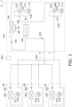
- a refrigeration cycle system 1 has a configuration shown in FIG. 1 .
- the refrigeration cycle system 1 includes a first refrigerant circuit 100 through which a first refrigerant circulates and a second refrigerant circuit 200 through which a carbon dioxide refrigerant (CO 2 refrigerant) circulates.
- the refrigeration cycle system 1 is a device that performs indoor air conditioning by exchanging heat between a carbon dioxide refrigerant as a heat transfer medium and indoor air. Examples of the indoor air conditioning include cooling and heating.
- the first refrigerant circuit 100 includes a first compressor 110, a first four-way valve 120, an outdoor air heat exchanger 130, and a cascade heat exchanger 150.
- the first refrigerant used in the first refrigerant circuit 100 for example, R32, R454C, propane, R1234yf, R1234ze, or ammonia can be used.
- a refrigerant including any of R32, R454C, propane, R1234yf, R1234ze, or ammonia can be used as the first refrigerant.
- the outdoor air heat exchanger 130 is an example of an outdoor heat exchanger.
- the first compressor 110 is a device that compresses the first refrigerant in a gaseous state.
- a positive displacement compressor can be used.
- the positive displacement compressor include a rotary compressor and a scroll compressor.
- the first compressor 110 is driven by, for example, a motor 115.
- the motor 115 is, for example, a motor including an inverter and capable of changing a rotational speed. By changing the rotational speed of the motor 115, the first compressor 110 can adjust a discharge capacity.
- the first four-way valve 120 is a device for switching a flow of the first refrigerant in first refrigerant circuit 100. Specifically, the first four-way valve 120 switches between a communication state indicated by a solid line of the first four-way valve 120 in FIG. 1 and a communication state indicated by a broken line of the first four-way valve 120 in FIG. 1 .
- the first four-way valve 120 can be replaced with another configuration having a function of switching between a first refrigerant heat radiation state and a first refrigerant evaporation state by combining a plurality of valves (for example, electromagnetic valves or three-way valves) other than four-way valves.
- the first refrigerant circuit 100 enters the first refrigerant heat radiation state in which the outdoor air heat exchanger 130 functions as a radiator for the first refrigerant and the cascade heat exchanger 150 functions as an evaporator for the first refrigerant.
- the first refrigerant heat radiation state is a state in which the first refrigerant is cooled by outside air (outdoor air).
- the first refrigerant circuit 100 enters the first refrigerant evaporation state in which the outdoor air heat exchanger 130 functions as an evaporator for the first refrigerant and the cascade heat exchanger 150 functions as a radiator for the first refrigerant.
- the first refrigerant evaporation state is a state in which the first refrigerant is heated by outside air.
- a discharge port of the first compressor 110 communicates with the outdoor air heat exchanger 130, and a suction port of the first compressor 110 communicates with the cascade heat exchanger 150.
- the discharge port of the first compressor 110 in the first refrigerant evaporation state, communicates with the cascade heat exchanger 150, and the suction port of the first compressor 110 communicates with the outdoor air heat exchanger 130.
- the outdoor air heat exchanger 130 is a device that exchanges heat between the first refrigerant and outside air.
- the outdoor air heat exchanger 130 is, for example, a fin-and-tube heat exchanger.
- the outdoor air heat exchanger 130 In a state where the first four-way valve 120 is switched to the first refrigerant heat radiation state (state indicated by the solid line), the outdoor air heat exchanger 130 functions as a radiator for the first refrigerant using the outside air as a cooling source.
- the outdoor air heat exchanger 130 functions as an evaporator for the first refrigerant using the outside air as a heating source.
- the outdoor air heat exchanger 130 communicates with the first four-way valve 120 and a first expansion valve 140.
- the first refrigerant circuit 100 includes the first expansion valve 140.
- the first expansion valve 140 is a device that decompresses the first refrigerant.
- the first expansion valve 140 is a device for adjusting the pressure of the first refrigerant having passed or adjusting the flow rate of the refrigerant.
- the first expansion valve 140 is, for example, an electric expansion valve that changes an opening degree in accordance with an electric signal.
- the first expansion valve 140 is provided between the outdoor air heat exchanger 130 and the cascade heat exchanger 150.
- the first expansion valve 140 adjusts the pressure of the first refrigerant flowing between the outdoor air heat exchanger 130 and the cascade heat exchanger 150.
- the first expansion valve 140 decompresses the first refrigerant that has radiated heat in the outdoor air heat exchanger 130. In a state where the first four-way valve 120 is switched to the first refrigerant evaporation state, the first expansion valve 140 decompresses the first refrigerant having radiated heat in the cascade heat exchanger 150.
- the first expansion valve 140 is not limited to the electric expansion valve. As the first expansion valve 140, for example, an expansion valve or a capillary tube of a type other than the electric expansion valve may be used.
- the cascade heat exchanger 150 is a device that exchanges heat between the first refrigerant and the carbon dioxide refrigerant.
- the cascade heat exchanger 150 for example, a plate heat exchanger, a double tube heat exchanger, or a shell-and-tube heat exchanger can be used.
- the cascade heat exchanger 150 functions as an evaporator for the first refrigerant using the carbon dioxide refrigerant as a heating source.
- the cascade heat exchanger 150 functions as a radiator for the first refrigerant using the carbon dioxide refrigerant as a cooling source.
- the cascade heat exchanger 150 communicates with the first four-way valve 120, and communicates with the cascade heat exchanger 150 via the first expansion valve 140.
- the second refrigerant circuit 200 includes a second compressor 210, a cascade heat exchanger 150, a second four-way valve 220, and a plurality of indoor air heat exchangers 251, 252, and 253.
- the indoor air heat exchangers 251, 252, and 253 are an example of indoor heat exchangers.
- the carbon dioxide refrigerant circulates as the heat transfer medium.
- the second refrigerant circuit 200 includes three indoor air heat exchangers 251, 252, and 253. However, the number of indoor air heat exchangers may be one, two, or four or more.
- the cascade heat exchanger 150 is shared by two circuits, namely, the first refrigerant circuit 100 and the second refrigerant circuit 200.
- the second compressor 210 is a device that compresses the carbon dioxide refrigerant in a gaseous state.
- a positive displacement compressor can be used.
- the positive displacement compressor include a rotary compressor and a scroll compressor.
- the second compressor 210 is driven by, for example, a motor 215.
- the motor 215 is, for example, a motor including an inverter and capable of changing a rotational speed. By changing the rotational speed of the motor 215, the second compressor 210 can adjust a discharge capacity.
- the second four-way valve 220 is a device for switching the flow of the carbon dioxide refrigerant in the second refrigerant circuit 200. Specifically, the second four-way valve 220 switches between a communication state indicated by a solid line of the second four-way valve 220 in FIG. 1 and a communication state indicated by a broken line of the second four-way valve 220 in FIG. 1 .
- the second four-way valve 220 can be replaced with another configuration having a function of switching between a CO 2 heat radiation state and a CO 2 evaporation state by combining a plurality of valves (for example, electromagnetic valves or three-way valves).
- the second refrigerant circuit 200 enters the CO 2 evaporation state in which the indoor air heat exchangers 251, 252, and 253 function as an evaporator for the carbon dioxide refrigerant and the cascade heat exchanger 150 functions as a radiator for the carbon dioxide refrigerant.
- the CO 2 evaporation state is a state in which the carbon dioxide refrigerant evaporates to cool the indoor air.
- the second refrigerant circuit 200 enters the CO 2 heat radiation state in which the indoor air heat exchangers 251, 252, and 253 function as a radiator for the carbon dioxide refrigerant and the cascade heat exchanger 150 functions as an evaporator for the carbon dioxide refrigerant.
- the CO 2 heat radiation state is a state in which the carbon dioxide refrigerant radiates heat to indoor air.
- a discharge port of the second compressor 210 communicates with the indoor air heat exchangers 251, 252, and 253, and a suction port of the second compressor 210 communicates with the cascade heat exchanger 150.
- the discharge port of the second compressor 210 communicates with the cascade heat exchanger 150, and the suction port of the second compressor 210 communicates with the indoor air heat exchangers 251, 252, and 253.
- Each of the indoor air heat exchangers 251, 252, and 253 is, for example, a device that exchanges heat between indoor air in a corresponding room and the carbon dioxide refrigerant.
- the indoor air heat exchangers 251, 252, and 253 are, for example, fin-and-tube heat exchangers.
- the indoor air heat exchangers 251, 252, and 253 function as a radiator for the carbon dioxide refrigerant in order to heat the indoor air in a state where the second four-way valve 220 is switched to the CO 2 heat radiation state.
- the indoor air heat exchangers 251, 252, and 253 function as a radiator of a carbon dioxide refrigerant using the indoor air as a cooling source in the CO 2 heat radiation state.
- the indoor air heat exchangers 251, 252, and 253 function as an evaporator for the carbon dioxide refrigerant in order to cool the indoor air.
- the indoor air heat exchangers 251, 252, and 253 function as an evaporator for the carbon dioxide refrigerant using the indoor air as a heating source in the CO 2 evaporation state.
- the indoor air heat exchangers 251, 252, and 253 communicate with the suction port of the second compressor 210 via the second four-way valve 220, and communicate with the cascade heat exchanger 150 via corresponding second expansion valves 261, 262, and 263, respectively, and a third expansion valve 230.
- the second refrigerant circuit 200 includes the second expansion valves 261, 262, and 263 and the third expansion valve 230.
- the second expansion valves 261, 262, and 263 and the third expansion valve 230 are devices for adjusting the pressure of the carbon dioxide refrigerant having passed and adjusting the flow rate of the carbon dioxide refrigerant.
- the second expansion valves 261, 262, and 263 and the third expansion valve 230 are, for example, electric expansion valves that change the opening degree in accordance with an electric signal.
- the third expansion valve 230 is connected to the cascade heat exchanger 150.
- the third expansion valve 230 is connected to all the second expansion valves 261, 262, and 263.
- the second expansion valves 261, 262, and 263 are connected to the corresponding indoor air heat exchangers 251, 252, and 253, respectively.
- the second expansion valves 261, 262, and 263 are provided between the corresponding indoor air heat exchangers 251, 252, and 253 and the cascade heat exchanger 150.
- the second expansion valves 261, 262, and 263 adjust the pressure of the carbon dioxide refrigerant flowing through the corresponding indoor air heat exchangers 251, 252, and 253.
- the second expansion valves 261, 262, and 263 decompress the carbon dioxide refrigerant that has radiated heat in the indoor air heat exchangers 251, 252, and 253 in a state where the second four-way valve 220 is switched to the CO 2 heat radiation state.
- the second expansion valves 261, 262, and 263 decompress the carbon dioxide refrigerant to be sent to the indoor air heat exchangers 251, 252, and 253 in a state where the second four-way valve 220 is switched to the CO 2 evaporation state.
- the third expansion valve 230 is provided between all the indoor air heat exchangers 251, 252, and 253 and the cascade heat exchanger 150.
- the third expansion valve 230 adjusts the pressure of the carbon dioxide refrigerant flowing from the indoor air heat exchangers 251, 252, and 253 to the cascade heat exchanger 150.
- the third expansion valve 230 is fully opened so as not to decompress the carbon dioxide refrigerant that has radiated heat in the cascade heat exchanger 150 as much as possible.
- the third expansion valve 230 decompresses the carbon dioxide refrigerant that has radiated heat in the indoor air heat exchangers 251, 252, and 253 in a state where the second four-way valve 220 is switched to the CO 2 heat radiation state.
- the third expansion valve 230 is not limited to the electric expansion valve.
- an expansion valve or a capillary tube of a type other than the electric expansion valve may be used.
- the cascade heat exchanger 150 functions as a radiator for the carbon dioxide refrigerant using the first refrigerant as a cooling source in a state where the first four-way valve 120 is switched to the first refrigerant heat radiation state (state indicated by the solid line) and the second four-way valve 220 is switched to the CO 2 evaporation state (state indicated by the solid line).
- the cascade heat exchanger 150 functions as an evaporator for the carbon dioxide refrigerant using the first refrigerant as a heating source in a state where first four-way valve 120 is switched to the first refrigerant evaporation state (state indicated by the broken line) and the second four-way valve 220 is switched to the CO 2 heat radiation state (state indicated by the broken line).
- the cascade heat exchanger 150 communicates with the second four-way valve 220 and communicates with the indoor air heat exchangers 251, 252, and 253 via the third expansion valve 230 and the second expansion valves 261, 262, and 263 in order to cause the carbon dioxide refrigerant to flow.
- the constituent devices of the first refrigerant circuit 100 and the second refrigerant circuit 200 are provided in a heat transfer unit 2 and a plurality of utilization units 5a, 5b, and 5c.
- the utilization units 5a, 5b, and 5c are provided corresponding to the indoor air heat exchangers 251, 252, and 253, respectively.
- the heat transfer unit 2 is disposed outdoors.
- the cascade heat exchanger 150, the second compressor 210, the third expansion valve 230, and the second four-way valve 220 are provided in the heat transfer unit 2.
- the heat transfer unit 2 is provided with an outdoor fan 160 that supplies outside air to the outdoor air heat exchanger 130.
- the outdoor fan 160 is driven by, for example, a motor 165 that can change a rotational speed.
- the outdoor fan 160 is, for example, a propeller fan.
- the outdoor fan 160 can change the volume of airflow passing through the outdoor air heat exchanger 130 by changing the rotational speed of the motor 165.
- the utilization units 5a, 5b, and 5c are disposed indoors.
- the indoor air heat exchangers 251, 252, and 253 of the second refrigerant circuit 200 are accommodated in the utilization units 5a, 5b, and 5c, respectively.
- the second expansion valves 261, 262, and 263 of the second refrigerant circuit 200 are also accommodated in the utilization units 5a, 5b, and 5c, respectively.
- the utilization units 5a, 5b, and 5c accommodate indoor fans 271, 272, and 273 that supplies indoor air to the indoor air heat exchangers 251, 252, and 253, respectively.
- the indoor fans 271, 272, and 273 are, for example, centrifugal fans or multiblade fans.
- the indoor fans 271, 272, and 273 are driven by motors 276, 277, and 278, respectively.
- Each of the motors 276, 277, and 278 is, for example, a motor including an inverter and capable of changing a rotational speed.
- the indoor fans 271, 272, and 273 can change the volume of airflow passing through the indoor air heat exchangers 251, 252, and 253.
- connection pipes 6 and 7 constituting a part of the second refrigerant circuit 200.
- the connection pipe 6 is a pipe for allowing the cascade heat exchanger 150 and one end of the second expansion valves 261, 262, and 263 to communicate with each other.
- the connection pipe 7 is a pipe for allowing the second four-way valve 220 and the indoor air heat exchangers 251, 252, and 253 to communicate with each other.
- the constituent devices of the heat transfer unit 2 and the utilization units 5a, 5b, and 5c are controlled by a controller 300.
- the controller 300 is configured by, for example, communicably connecting control boards (not shown) provided in the heat transfer unit 2 and the utilization units 5a, 5b, and 5c. In FIG. 1 , for convenience, the controller 300 is shown at a position away from the heat transfer unit 2 and the utilization units 5a, 5b, and 5c.
- the controller 300 controls the constituent devices of the refrigeration cycle system 1 (here, the heat transfer unit 2 and the utilization units 5a, 5b, and 5c). In other words, the controller 300 controls the operation of the entire refrigeration cycle system 1.
- the controller 300 is achieved by a computer.
- the controller 300 includes a control calculation device and a storage device.
- a processor such as a CPU or a GPU can be used for the control calculation device.
- the control calculation device reads a program stored in the storage device, and executes predetermined image processing and calculation processing in accordance with this program. Furthermore, the control calculation device can write a calculation result to the storage device and read information stored in the storage device in accordance with the program.
- the refrigeration cycle system 1 includes the heat transfer unit 2, the plurality of utilization units 5a, 5b, and 5c connected in parallel to each another, the connection pipes 6 and 7 connecting the heat transfer unit 2 and the utilization units 5a, 5b, and 5c, and the controller 300 that controls the constituent devices of the heat transfer unit 2 and the utilization units 5a, 5b, and 5c.
- FIG. 2 shows a behavior (flow of the first refrigerant and the carbon dioxide refrigerant) in the cooling operation of the refrigeration cycle system 1.
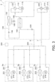
- FIG. 3 shows a behavior in the heating operation.
- the refrigeration cycle system 1 can perform the cooling operation for cooling indoor air and the heating operation for heating indoor air for indoor air conditioning. In the cooling operation and the heating operation, the behavior of the refrigeration cycle system 1 is controlled by the controller 300.
- the first four-way valve 120 is switched to the first refrigerant heat radiation state (the first four-way valve 120 is in the state indicated by the solid line), and the second four-way valve 220 is switched to the CO 2 evaporation state (the second four-way valve 220 is in the state indicated by the solid line).
- the first refrigerant discharged from the first compressor 110 is sent to the outdoor air heat exchanger 130 through the first four-way valve 120.
- the first refrigerant sent to the outdoor air heat exchanger 130 exchanges heat with the outside air supplied by the outdoor fan 160 and is cooled to be condensed.
- the first refrigerant having radiated heat in the outdoor air heat exchanger 130 is decompressed by the first expansion valve 140 and then sent to the cascade heat exchanger 150.
- the first refrigerant sent to the cascade heat exchanger 150 is heated and evaporated by exchanging heat with the carbon dioxide refrigerant in the cascade heat exchanger 150 functioning as an evaporator for the first refrigerant.
- the first refrigerant evaporated in the cascade heat exchanger 150 is sucked into the first compressor 110 through the first four-way valve 120, and is discharged again from the first compressor 110.
- the carbon dioxide refrigerant discharged from the second compressor 210 is sent to the cascade heat exchanger 150 through the second four-way valve 220.
- the carbon dioxide refrigerant sent to the cascade heat exchanger 150 exchanges heat with the first refrigerant in the cascade heat exchanger 150 functioning as a radiator for the carbon dioxide refrigerant to be cooled.
- the carbon dioxide refrigerant having radiated heat in the cascade heat exchanger 150 passes through the third expansion valve 230 in a fully opened state, and then is sent to the connection pipe 6 to be branched.
- the carbon dioxide refrigerant branched at the connection pipe 6 is decompressed by the second expansion valves 261, 262, and 263 and then sent to the indoor air heat exchangers 251, 252, and 253.
- the carbon dioxide refrigerant sent to the indoor air heat exchangers 251, 252, and 253 exchanges heat with indoor air supplied by the indoor fans 271, 272, and 273 and is heated to be evaporated.
- the cooling operation for cooling indoor air is performed.
- the carbon dioxide refrigerant evaporated in the indoor air heat exchangers 251, 252, and 253 merges at the connection pipe 7.
- the carbon dioxide refrigerant having merged at the connection pipe 7 is sucked into the second compressor 210 through the second four-way valve 220, and is discharged again from the second compressor 210.
- the first refrigerant circuit 100 executes a first vapor compression refrigeration cycle using the first refrigerant.
- the second refrigerant circuit 200 executes a second vapor compression refrigeration cycle using the carbon dioxide refrigerant as the second refrigerant.
- the first compressor 110 circulates the first refrigerant in the first refrigerant circuit 100 at a discharge refrigerant pressure in a range of 0.5 [MPa] or more and to 4 [MPa] or less.
- the second compressor 210 circulates the carbon dioxide refrigerant at a discharge refrigerant pressure in a range of 5 [MPa] or more and 14 [MPa] or less.
- the second refrigerant circuit 200 operates such that the carbon dioxide refrigerant is condensed by the cascade heat exchanger 150.
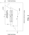
- FIG. 4 a Mollier diagram M100 of the first refrigerant circuit 100 and a Mollier diagram M200 of the second refrigerant circuit 200 are illustrated by overlapping graphs having different vertical axes.
- FIG. 4 shows an image to describe heat exchange in the cascade heat exchanger 150, and thus is not a detailed drawing.
- the first refrigerant circuit 100 operates such that a pressure (condensation pressure PH1) of the first refrigerant discharged from the first compressor 110 satisfies a condition of 0.5 [MPa] ⁇ PH1 ⁇ 4 [MPa].
- the second refrigerant circuit 200 operates such that a pressure (evaporation pressure PL1) of the carbon dioxide refrigerant discharged from the second compressor 210 satisfies a condition of 5 [MPa] ⁇ PH2 ⁇ 14 [MPa].
- a portion surrounded by a square frame line in FIG. 4 indicates a place where heat is exchanged between the carbon dioxide refrigerant in a gaseous state of high temperature and high pressure and the first refrigerant in a liquid state of low temperature and low pressure or a gas-liquid two-phase state in the cascade heat exchanger 150.
- the controller 300 controls the first compressor 110 and the second compressor 210 such that a target value TV [°C] of an intermediate temperature Tm between an evaporation temperature Te of the first refrigerant and a condensation temperature Tc of the carbon dioxide refrigerant in the cascade heat exchanger 150 satisfies the following formula (1), where T1 [°C] represents a pressure equivalent saturation temperature of the refrigerant discharged from first compressor 110, and T2 [°C] represents a pressure equivalent saturation temperature of the refrigerant sucked into the second compressor 210.
- the controller 300 adjusts the rotational speeds of the first compressor 110 and the second compressor 210, for example.
- the intermediate temperature Tm is a temperature between the evaporation temperature Te of the first refrigerant and the condensation temperature Tc of the carbon dioxide refrigerant.
- a method of controlling the first compressor 110 and the second compressor 210 such that the intermediate temperature Tm becomes the target value TV is not limited to such a method.
- the controller 300 can be configured to control the first compressor 110 and the second compressor 210 such that the intermediate temperature Tm does not deviate from a predetermined range (for example, a range of ⁇ T2 + (T1 - T2) ⁇ 0.1 ⁇ or more and ⁇ T2 + (T1 - T2) ⁇ 0.4 ⁇ or less) of the target value TV.
- a predetermined range for example, a range of ⁇ T2 + (T1 - T2) ⁇ 0.1 ⁇ or more and ⁇ T2 + (T1 - T2) ⁇ 0.4 ⁇ or less
- a plurality of the target values TV may be prepared and switched in accordance with a situation (for example, outside air temperature).
- the controller 300 performs control similar to conventional control except that the first compressor 110 and the second compressor 210 are controlled such that intermediate temperature Tm in the cascade heat exchanger 150 becomes the target value TV.
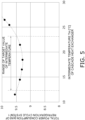
- the horizontal axis represents the intermediate temperature Tm when the pressure equivalent saturation temperature T1 of the refrigerant discharged from the first compressor 110 is 45 [°C] and the pressure equivalent saturation temperature T2 of the refrigerant sucked into the second compressor 210 is 8 [°C].
- FIG. 5 shows a relationship between the intermediate temperature Tm and a total power consumption of the refrigeration cycle system 1.
- the total power consumption [kW] of the refrigeration cycle system 1 is a power consumption of the refrigeration cycle system 1, and is the sum of a power consumption [kW] of the first refrigerant circuit 100 and a power consumption [kW] of the second refrigerant circuit.
- the vertical axis represents power consumption necessary for obtaining predetermined capability in the cascade heat exchanger 150.
- the graph indicating the relationship between the intermediate temperature Tm of the first refrigerant circuit 100 and the total power consumption of the refrigeration cycle system 1 has a downward convex shape, and that there is a range in which the power consumption can be reduced. It can be understood from FIG. 5 that it is preferable to set the target value TV of the intermediate temperature Tm within a range where the total power consumption is 9.5 [kW] or less. Furthermore, in the case as shown in FIG. 5 , it is more preferable to set the target value TV of the intermediate temperature Tm within a range where the total power consumption is 9.4 [kW] or less. The tendency shown in FIG.
- first compressor that circulates the first refrigerant at the discharge refrigerant pressure in a range of 0.5 MPa or more and 4 MPa or less and the second compressor that circulates the second refrigerant at the discharge refrigerant pressure in a range of 5 MPa or more and 14 MPa or less.
- FIG. 6 shows a relationship between a value obtained by normalizing the intermediate temperature Tm and the intermediate temperature.
- FIG. 6 shows a value obtained by normalizing the intermediate temperature when the pressure equivalent saturation temperature 8 [°C] of the refrigerant sucked into the second compressor 210 is "0" and the pressure equivalent saturation temperature 45 [°C] of the refrigerant discharged from the first compressor 110 is "1".
- a range (range of the target value) in which the normalized value is 0.1 or more and 0.4 or less is indicated by an arrow in FIG. 5 . It can be understood from FIG. 5 that the total power consumption in the range indicated by the arrow represents a low value.
- the target value TV satisfies T2 + (T1 - T2) ⁇ 0.1 ⁇ TV ⁇ T2 + (T1 - T2) ⁇ 0.4, and thus, the total power consumption represents a low value.
- the normalized value is preferably 0.15 or more and 0.35 or less.
- the target value TV preferably satisfies T2 + (T1 - T2) ⁇ 0.15 ⁇ TV ⁇ T2 + (T1 - T2) ⁇ 0.35.
- the controller 300 may control the first compressor 110 and the second compressor 210 such that the intermediate temperature Tm in the cascade heat exchanger 150 satisfies the following formula (2).
- a target evaporation temperature Tme of evaporation temperature Te of the first refrigerant in the cascade heat exchanger 150 is set, the first compressor 110 is controlled to reach the target evaporation temperature Tme, and a target condensation temperature Tme of the condensation temperature Tc of the carbon dioxide refrigerant is set, and the second compressor 210 is controlled to reach the target condensation temperature Tmc.
- the target condensation temperature Tmc and the target evaporation temperature Tme are set to values within a range where the intermediate temperature Tm satisfies the above formula (2) on the basis of the total power consumption of the refrigeration cycle system 1 during the operation of the first compressor 110 and the second compressor 210.
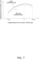
- FIG. 7 shows a relationship between the rotational speed and the compressor efficiency of each of the first compressor 110 and the second compressor 210.
- both the first compressor 110 and the second compressor 210 have the highest compressor efficiency near a rotational speed R.
- R is a value between a lower limit value Rmin and an upper limit value Rmax.
- the compressor efficiency gradually decreases as the rotational speed becomes smaller than near R, and becomes the lowest at the lower limit value Rmin of the rotational speed.
- the compressor efficiency decreases as the rotational speed becomes larger than near R, and the compressor efficiency at the upper limit value Rmax of the rotational speed is lower than the compressor efficiency near the rotational speed R.
- the compressor efficiency of the second compressor 210 is lower than the compressor efficiency of the first compressor 110 by about several percent in an entire range from the lower limit value Rmin of the rotational speed to the upper limit value Rmax of the rotational speed used in the refrigeration cycle system 1. This tendency is caused by the fact that a discharge pressure of the second compressor 210 is higher than a discharge pressure of the first compressor 110.
- the refrigeration cycle system 1 includes a high-pressure pressure sensor 410 on a discharge side of the first compressor 110 for detecting the pressure equivalent saturation temperature T1 of the refrigerant discharged from the first compressor 110.
- the refrigeration cycle system 1 includes a low-pressure pressure sensor 420 on a suction side of the second compressor 210 for detecting the pressure equivalent saturation temperature T2 of the refrigerant sucked into the second compressor 210.
- a low-pressure pressure sensor 430 for detecting the evaporation temperature Te of the cascade heat exchanger 150 is provided on a suction side of the first compressor 110.
- a high-pressure pressure sensor 440 for detecting the condensation temperature Tc of the cascade heat exchanger 150 is provided on a discharge side of the second compressor 210.
- the controller 300 of the refrigeration cycle system 1 uses detection results of various sensors other than the pressure sensors 410, 420, 430, and 440. However, sensors similar to the conventional sensors may be used, and thus sensors other than the pressure sensors 410, 420, 430, and 440 is are not described here.
- the first four-way valve 120 is switched to the first refrigerant evaporation state (the first four-way valve 120 is in the state indicated by the broken line), and the second four-way valve 220 is switched to the CO 2 heat radiation state (the second four-way valve 220 is in the state indicated by the broken line).
- the first refrigerant discharged from the first compressor 110 is sent to the cascade heat exchanger 150 through the first four-way valve 120.
- the first refrigerant sent to the cascade heat exchanger 150 exchanges heat with the carbon dioxide refrigerant and is cooled to be condensed.
- the first refrigerant having radiated heat in the cascade heat exchanger 150 is decompressed by the first expansion valve 140 and then sent to the outdoor air heat exchanger 130.
- the first refrigerant sent to the outdoor air heat exchanger 130 exchanges heat with the outside air supplied by the outdoor fan 160 in the outdoor air heat exchanger 130 to be heated and evaporated.
- the first refrigerant evaporated in the outdoor air heat exchanger 130 is sucked into the first compressor 110 through the first four-way valve 120, and is discharged again from the first compressor 110.
- the carbon dioxide refrigerant discharged from the second compressor 210 passes through the second four-way valve 220, and then, is branched at the connection pipe 7.
- the carbon dioxide refrigerant branched at the connection pipe 7 is sent to the indoor air heat exchangers 251, 252, and 253.
- the carbon dioxide refrigerant sent to the indoor air heat exchangers 251, 252, and 253 exchanges heat with indoor air supplied by the indoor fans 271, 272, and 273 and is cooled.
- the heating operation for heating indoor air is performed.
- the carbon dioxide refrigerant having radiated heat in the indoor air heat exchangers 251, 252, and 253 is decompressed by the second expansion valves 261, 262, and 263 and then joins at the connection pipe.
- the carbon dioxide refrigerant joined at the connection pipe 6 is further decompressed by the third expansion valve 230 and then sent to the cascade heat exchanger 150.
- the carbon dioxide refrigerant sent to the cascade heat exchanger 150 exchanges heat with the first refrigerant to be heated.
- the carbon dioxide refrigerant that has passed through the cascade heat exchanger 150 is sucked into the second compressor 210 through the second four-way valve 220, and is discharged again from the second compressor 210.
- the first refrigerant circuit 100 executes a first vapor compression refrigeration cycle using the first refrigerant.
- the second refrigerant circuit 200 executes a second vapor compression refrigeration cycle using the carbon dioxide refrigerant as the second refrigerant.
- the controller 300 controls the first compressor 110 such that the intermediate temperature Tm in the cascade heat exchanger 150 becomes the target value TV that satisfies T2 + (T1 - T2) ⁇ 0.1 ⁇ TV ⁇ T2 + (T1 - T2) ⁇ 0.4.
- T1 [°C] is the pressure equivalent saturation temperature of the refrigerant discharged from the first compressor 110
- T2 [°C] is the pressure equivalent saturation temperature of the refrigerant sucked into the second compressor 210.
- the first compressor 110 and the second compressor 210 it is preferable to control the first compressor 110 and the second compressor 210 such that the intermediate temperature Tm satisfies T2 + (T1 - T2) ⁇ 0.15 ⁇ TV ⁇ T2 + (T1 - T2) ⁇ 0.35.
- the controller 300 By performing such control by the controller 300, the amount of heat can be increased in the first refrigerant circuit 100 including the first compressor 110 having high efficiency, and the power consumption of the entire refrigeration cycle system 1 can be reduced.
- a detection device used to detect the temperatures is not limited to a pressure sensor. Examples of the detection device other than a pressure sensor include a temperature sensor.
- the constituent devices of the first refrigerant circuit 100 and the second refrigerant circuit 200 are provided in the heat transfer unit 2 and the plurality of utilization units 5a, 5b, and 5c.
- the cascade heat exchanger 150 and the second compressor 210 of the second refrigerant circuit 200 may be provided in a separate cascade unit instead of the heat transfer unit and the utilization unit.
- Patent Literature 1 JP 2002-147819 A
Landscapes
- Engineering & Computer Science (AREA)
- Physics & Mathematics (AREA)
- Mechanical Engineering (AREA)
- Thermal Sciences (AREA)
- General Engineering & Computer Science (AREA)
- Chemical & Material Sciences (AREA)
- Chemical Kinetics & Catalysis (AREA)
- Compression-Type Refrigeration Machines With Reversible Cycles (AREA)
Abstract
Description
- The present disclosure relates to a refrigeration cycle system including a cascade heat exchanger that exchanges heat between a first refrigerant circulating in a first refrigerant circuit and a second refrigerant that is a CO2 refrigerant circulating in a second refrigerant circuit.
- In recent years, in order to reduce power consumption in the whole society, it is required to reduce power consumption of an air conditioner and the like. For example, Patent Literature 1 (
JP 2002-147819 A Patent Literature 1, a controller controls a capacity of a compressor unit such that a detected current value is within a range that does not exceed a predetermined set value. - In the refrigeration apparatus described in
Patent Literature 1 and the like, a method of reducing power consumption when one type of refrigerant is circulated is proposed. However, it is difficult to directly apply the method described inPatent Literature 1 to a refrigeration cycle system that performs air conditioning or the like by a plurality of refrigeration cycles using different types of refrigerants. There is a problem of reducing power consumption in a refrigeration cycle system that includes a cascade heat exchanger that causes heat exchange between a CO2 refrigerant and a refrigerant other than CO2 and that implements a first refrigeration cycle using the CO2 refrigerant and a second refrigeration cycle using the refrigerant other than CO2. - A refrigeration cycle system according to a first aspect includes a first refrigerant circuit, a second refrigerant circuit, and a controller. The first refrigerant circuit includes a first compressor that circulates a first refrigerant at a discharge refrigerant pressure in a range of 0.5 MPa or more and 4 MPa or less, and a cascade heat exchanger that cools a second refrigerant that is a CO2 refrigerant by the first refrigerant, and implements a first vapor compression refrigeration cycle using the first refrigerant. The second refrigerant circuit includes a second compressor that circulates the second refrigerant at a discharge refrigerant pressure in a range of 5 MPa or more and 14 MPa or less, and implements a second vapor compression refrigeration cycle using the second refrigerant. The controller controls the first compressor and the second compressor. The controller controls the first compressor and the second compressor such that an intermediate temperature between an evaporation temperature of the first refrigerant and a condensation temperature of the second refrigerant in the cascade heat exchanger satisfies T2 + (T1 - T2) × 0.1 ≤ TV ≤ T2 + (T1 - T2) × 0.4, where T1°C represents a pressure equivalent saturation temperature of a refrigerant discharged from the first compressor, and T2°C represents a pressure equivalent saturation temperature of a refrigerant sucked into the second compressor.
- In the refrigeration cycle system according to the first aspect, the first refrigerant circuit including the first compressor more efficient than the second compressor transports a larger amount of heat, and thus, power consumption as a whole can be reduced.
- A refrigeration cycle system according to a second aspect is the system according to the first aspect, in which the first refrigerant is R32, R454C, propane, R1234yf, R1234ze, or ammonia, or a refrigerant including any of R32, R454C, propane, R1234yf, R1234ze, or ammonia.
- A refrigeration cycle system according to a third aspect is the system according to the first or second aspect, in which the second refrigerant circuit condenses the second refrigerant in the cascade heat exchanger.
- A refrigeration cycle system according to a fourth aspect is the system according to the third aspect, in which the second refrigerant circuit includes an indoor heat exchanger that causes heat exchange between indoor air and the second refrigerant.
- A refrigeration cycle system according to a fifth aspect is the system according to the fourth aspect, in which the first refrigerant circuit includes an outdoor heat exchanger that causes heat exchange between outside air and the first refrigerant.
-
-
FIG. 1 is a circuit diagram showing a schematic configuration of a refrigeration cycle system according to an embodiment. -
FIG. 2 is a circuit diagram of a refrigeration cycle system in which a flow direction of a refrigerant during a cooling operation is added toFIG. 1 . -
FIG. 3 is a circuit diagram of a refrigeration cycle system in which a flow direction of a refrigerant during a heating operation is added toFIG. 1 . -
FIG. 4 is a conceptual diagram using a Mollier diagram for describing heat exchange in a cascade heat exchanger. -
FIG. 5 is a graph showing a relationship between an intermediate temperature of the cascade heat exchanger and a total power consumption of the refrigeration cycle system. -
FIG. 6 is a diagram for describing a relationship between a value obtained by normalizing the intermediate temperature of the cascade heat exchanger and the intermediate temperature. -
FIG. 7 is a graph showing a relationship between rotational speeds of a first compressor and a second compressor and compressor efficiency. - A
refrigeration cycle system 1 according to an embodiment has a configuration shown inFIG. 1 . Therefrigeration cycle system 1 includes afirst refrigerant circuit 100 through which a first refrigerant circulates and asecond refrigerant circuit 200 through which a carbon dioxide refrigerant (CO2 refrigerant) circulates. Therefrigeration cycle system 1 is a device that performs indoor air conditioning by exchanging heat between a carbon dioxide refrigerant as a heat transfer medium and indoor air. Examples of the indoor air conditioning include cooling and heating. - The
first refrigerant circuit 100 includes afirst compressor 110, a first four-way valve 120, an outdoorair heat exchanger 130, and acascade heat exchanger 150. As the first refrigerant used in thefirst refrigerant circuit 100, for example, R32, R454C, propane, R1234yf, R1234ze, or ammonia can be used. Alternatively, a refrigerant including any of R32, R454C, propane, R1234yf, R1234ze, or ammonia can be used as the first refrigerant. The outdoorair heat exchanger 130 is an example of an outdoor heat exchanger. - The
first compressor 110 is a device that compresses the first refrigerant in a gaseous state. As thefirst compressor 110, for example, a positive displacement compressor can be used. Examples of the positive displacement compressor include a rotary compressor and a scroll compressor. Thefirst compressor 110 is driven by, for example, amotor 115. Themotor 115 is, for example, a motor including an inverter and capable of changing a rotational speed. By changing the rotational speed of themotor 115, thefirst compressor 110 can adjust a discharge capacity. - The first four-
way valve 120 is a device for switching a flow of the first refrigerant infirst refrigerant circuit 100. Specifically, the first four-way valve 120 switches between a communication state indicated by a solid line of the first four-way valve 120 inFIG. 1 and a communication state indicated by a broken line of the first four-way valve 120 inFIG. 1 . For example, the first four-way valve 120 can be replaced with another configuration having a function of switching between a first refrigerant heat radiation state and a first refrigerant evaporation state by combining a plurality of valves (for example, electromagnetic valves or three-way valves) other than four-way valves. - When the first four-
way valve 120 is switched to the communication state indicated by the solid line, thefirst refrigerant circuit 100 enters the first refrigerant heat radiation state in which the outdoorair heat exchanger 130 functions as a radiator for the first refrigerant and thecascade heat exchanger 150 functions as an evaporator for the first refrigerant. The first refrigerant heat radiation state is a state in which the first refrigerant is cooled by outside air (outdoor air). When the first four-way valve 120 is switched to the communication state indicated by the broken line, thefirst refrigerant circuit 100 enters the first refrigerant evaporation state in which the outdoorair heat exchanger 130 functions as an evaporator for the first refrigerant and thecascade heat exchanger 150 functions as a radiator for the first refrigerant. The first refrigerant evaporation state is a state in which the first refrigerant is heated by outside air. - In the first four-
way valve 120, in the first refrigerant heat radiation state, a discharge port of thefirst compressor 110 communicates with the outdoorair heat exchanger 130, and a suction port of thefirst compressor 110 communicates with thecascade heat exchanger 150. In the first four-way valve 120, in the first refrigerant evaporation state, the discharge port of thefirst compressor 110 communicates with thecascade heat exchanger 150, and the suction port of thefirst compressor 110 communicates with the outdoorair heat exchanger 130. - The outdoor
air heat exchanger 130 is a device that exchanges heat between the first refrigerant and outside air. The outdoorair heat exchanger 130 is, for example, a fin-and-tube heat exchanger. In a state where the first four-way valve 120 is switched to the first refrigerant heat radiation state (state indicated by the solid line), the outdoorair heat exchanger 130 functions as a radiator for the first refrigerant using the outside air as a cooling source. In a state where the first four-way valve 120 is switched to the first refrigerant evaporation state (state indicated by the broken line), the outdoorair heat exchanger 130 functions as an evaporator for the first refrigerant using the outside air as a heating source. The outdoorair heat exchanger 130 communicates with the first four-way valve 120 and afirst expansion valve 140. - The
first refrigerant circuit 100 includes thefirst expansion valve 140. Thefirst expansion valve 140 is a device that decompresses the first refrigerant. Thefirst expansion valve 140 is a device for adjusting the pressure of the first refrigerant having passed or adjusting the flow rate of the refrigerant. Thefirst expansion valve 140 is, for example, an electric expansion valve that changes an opening degree in accordance with an electric signal. Thefirst expansion valve 140 is provided between the outdoorair heat exchanger 130 and thecascade heat exchanger 150. Thefirst expansion valve 140 adjusts the pressure of the first refrigerant flowing between the outdoorair heat exchanger 130 and thecascade heat exchanger 150. In a state where the first four-way valve 120 is switched to the first refrigerant heat radiation state, thefirst expansion valve 140 decompresses the first refrigerant that has radiated heat in the outdoorair heat exchanger 130. In a state where the first four-way valve 120 is switched to the first refrigerant evaporation state, thefirst expansion valve 140 decompresses the first refrigerant having radiated heat in thecascade heat exchanger 150. Note that, thefirst expansion valve 140 is not limited to the electric expansion valve. As thefirst expansion valve 140, for example, an expansion valve or a capillary tube of a type other than the electric expansion valve may be used. - The
cascade heat exchanger 150 is a device that exchanges heat between the first refrigerant and the carbon dioxide refrigerant. As thecascade heat exchanger 150, for example, a plate heat exchanger, a double tube heat exchanger, or a shell-and-tube heat exchanger can be used. In a state where the first four-way valve 120 is switched to the first refrigerant heat radiation state, thecascade heat exchanger 150 functions as an evaporator for the first refrigerant using the carbon dioxide refrigerant as a heating source. In a state where the first four-way valve 120 is switched to the first refrigerant evaporation state, thecascade heat exchanger 150 functions as a radiator for the first refrigerant using the carbon dioxide refrigerant as a cooling source. Thecascade heat exchanger 150 communicates with the first four-way valve 120, and communicates with thecascade heat exchanger 150 via thefirst expansion valve 140. - The second
refrigerant circuit 200 includes asecond compressor 210, acascade heat exchanger 150, a second four-way valve 220, and a plurality of indoorair heat exchangers air heat exchangers refrigerant circuit 200, the carbon dioxide refrigerant circulates as the heat transfer medium. In this example, the secondrefrigerant circuit 200 includes three indoorair heat exchangers cascade heat exchanger 150 is shared by two circuits, namely, the firstrefrigerant circuit 100 and the secondrefrigerant circuit 200. - The
second compressor 210 is a device that compresses the carbon dioxide refrigerant in a gaseous state. As thesecond compressor 210, for example, a positive displacement compressor can be used. Examples of the positive displacement compressor include a rotary compressor and a scroll compressor. Thesecond compressor 210 is driven by, for example, amotor 215. Themotor 215 is, for example, a motor including an inverter and capable of changing a rotational speed. By changing the rotational speed of themotor 215, thesecond compressor 210 can adjust a discharge capacity. - The second four-
way valve 220 is a device for switching the flow of the carbon dioxide refrigerant in the secondrefrigerant circuit 200. Specifically, the second four-way valve 220 switches between a communication state indicated by a solid line of the second four-way valve 220 inFIG. 1 and a communication state indicated by a broken line of the second four-way valve 220 inFIG. 1 . For example, the second four-way valve 220 can be replaced with another configuration having a function of switching between a CO2 heat radiation state and a CO2 evaporation state by combining a plurality of valves (for example, electromagnetic valves or three-way valves). - When the second four-
way valve 220 is switched to the communication state indicated by the solid line, the secondrefrigerant circuit 200 enters the CO2 evaporation state in which the indoorair heat exchangers cascade heat exchanger 150 functions as a radiator for the carbon dioxide refrigerant. The CO2 evaporation state is a state in which the carbon dioxide refrigerant evaporates to cool the indoor air. When the second four-way valve 220 is switched to a communication state indicated by the broken line, the secondrefrigerant circuit 200 enters the CO2 heat radiation state in which the indoorair heat exchangers cascade heat exchanger 150 functions as an evaporator for the carbon dioxide refrigerant. The CO2 heat radiation state is a state in which the carbon dioxide refrigerant radiates heat to indoor air. - In the second four-
way valve 220, in the CO2 heat radiation state, a discharge port of thesecond compressor 210 communicates with the indoorair heat exchangers second compressor 210 communicates with thecascade heat exchanger 150. In the second four-way valve 220, in the CO2 evaporation state, the discharge port of thesecond compressor 210 communicates with thecascade heat exchanger 150, and the suction port of thesecond compressor 210 communicates with the indoorair heat exchangers - Each of the indoor
air heat exchangers air heat exchangers air heat exchangers way valve 220 is switched to the CO2 heat radiation state. In other words, the indoorair heat exchangers way valve 220 is switched to the CO2 evaporation state, the indoorair heat exchangers air heat exchangers air heat exchangers second compressor 210 via the second four-way valve 220, and communicate with thecascade heat exchanger 150 via correspondingsecond expansion valves third expansion valve 230. - The second
refrigerant circuit 200 includes thesecond expansion valves third expansion valve 230. Thesecond expansion valves third expansion valve 230 are devices for adjusting the pressure of the carbon dioxide refrigerant having passed and adjusting the flow rate of the carbon dioxide refrigerant. Thesecond expansion valves third expansion valve 230 are, for example, electric expansion valves that change the opening degree in accordance with an electric signal. Thethird expansion valve 230 is connected to thecascade heat exchanger 150. Thethird expansion valve 230 is connected to all thesecond expansion valves second expansion valves air heat exchangers - The
second expansion valves air heat exchangers cascade heat exchanger 150. Thesecond expansion valves air heat exchangers second expansion valves air heat exchangers way valve 220 is switched to the CO2 heat radiation state. Thesecond expansion valves air heat exchangers way valve 220 is switched to the CO2 evaporation state. - The
third expansion valve 230 is provided between all the indoorair heat exchangers cascade heat exchanger 150. Thethird expansion valve 230 adjusts the pressure of the carbon dioxide refrigerant flowing from the indoorair heat exchangers cascade heat exchanger 150. In a state where second four-way valve 220 is switched to the CO2 evaporation state, thethird expansion valve 230 is fully opened so as not to decompress the carbon dioxide refrigerant that has radiated heat in thecascade heat exchanger 150 as much as possible. Thethird expansion valve 230 decompresses the carbon dioxide refrigerant that has radiated heat in the indoorair heat exchangers way valve 220 is switched to the CO2 heat radiation state. However, thethird expansion valve 230 is not limited to the electric expansion valve. As thethird expansion valve 230, for example, an expansion valve or a capillary tube of a type other than the electric expansion valve may be used. - The
cascade heat exchanger 150 functions as a radiator for the carbon dioxide refrigerant using the first refrigerant as a cooling source in a state where the first four-way valve 120 is switched to the first refrigerant heat radiation state (state indicated by the solid line) and the second four-way valve 220 is switched to the CO2 evaporation state (state indicated by the solid line). Thecascade heat exchanger 150 functions as an evaporator for the carbon dioxide refrigerant using the first refrigerant as a heating source in a state where first four-way valve 120 is switched to the first refrigerant evaporation state (state indicated by the broken line) and the second four-way valve 220 is switched to the CO2 heat radiation state (state indicated by the broken line). Thecascade heat exchanger 150 communicates with the second four-way valve 220 and communicates with the indoorair heat exchangers third expansion valve 230 and thesecond expansion valves - The constituent devices of the first
refrigerant circuit 100 and the secondrefrigerant circuit 200 are provided in aheat transfer unit 2 and a plurality ofutilization units utilization units air heat exchangers - The
heat transfer unit 2 is disposed outdoors. Thecascade heat exchanger 150, thesecond compressor 210, thethird expansion valve 230, and the second four-way valve 220 are provided in theheat transfer unit 2. Theheat transfer unit 2 is provided with anoutdoor fan 160 that supplies outside air to the outdoorair heat exchanger 130. Theoutdoor fan 160 is driven by, for example, amotor 165 that can change a rotational speed. Theoutdoor fan 160 is, for example, a propeller fan. Theoutdoor fan 160 can change the volume of airflow passing through the outdoorair heat exchanger 130 by changing the rotational speed of themotor 165. - The
utilization units air heat exchangers refrigerant circuit 200 are accommodated in theutilization units second expansion valves refrigerant circuit 200 are also accommodated in theutilization units utilization units indoor fans air heat exchangers indoor fans indoor fans motors 276, 277, and 278, respectively. Each of themotors 276, 277, and 278 is, for example, a motor including an inverter and capable of changing a rotational speed. By changing the rotational speed of themotor 276, 277, and 278, theindoor fans air heat exchangers - The
heat transfer unit 2 and theutilization units connection pipes refrigerant circuit 200. Theconnection pipe 6 is a pipe for allowing thecascade heat exchanger 150 and one end of thesecond expansion valves connection pipe 7 is a pipe for allowing the second four-way valve 220 and the indoorair heat exchangers - The constituent devices of the
heat transfer unit 2 and theutilization units controller 300. Thecontroller 300 is configured by, for example, communicably connecting control boards (not shown) provided in theheat transfer unit 2 and theutilization units FIG. 1 , for convenience, thecontroller 300 is shown at a position away from theheat transfer unit 2 and theutilization units controller 300 controls the constituent devices of the refrigeration cycle system 1 (here, theheat transfer unit 2 and theutilization units controller 300 controls the operation of the entirerefrigeration cycle system 1. - The
controller 300 is achieved by a computer. Thecontroller 300 includes a control calculation device and a storage device. A processor such as a CPU or a GPU can be used for the control calculation device. The control calculation device reads a program stored in the storage device, and executes predetermined image processing and calculation processing in accordance with this program. Furthermore, the control calculation device can write a calculation result to the storage device and read information stored in the storage device in accordance with the program. - The
refrigeration cycle system 1 includes theheat transfer unit 2, the plurality ofutilization units connection pipes heat transfer unit 2 and theutilization units controller 300 that controls the constituent devices of theheat transfer unit 2 and theutilization units - Next, a behavior of the
refrigeration cycle system 1 is described with reference toFIGS. 1 to 3 .FIG. 2 shows a behavior (flow of the first refrigerant and the carbon dioxide refrigerant) in the cooling operation of therefrigeration cycle system 1.FIG. 3 shows a behavior in the heating operation. Therefrigeration cycle system 1 can perform the cooling operation for cooling indoor air and the heating operation for heating indoor air for indoor air conditioning. In the cooling operation and the heating operation, the behavior of therefrigeration cycle system 1 is controlled by thecontroller 300. - When all of the
utilization units way valve 120 is switched to the first refrigerant heat radiation state (the first four-way valve 120 is in the state indicated by the solid line), and the second four-way valve 220 is switched to the CO2 evaporation state (the second four-way valve 220 is in the state indicated by the solid line). - In the first
refrigerant circuit 100, the first refrigerant discharged from thefirst compressor 110 is sent to the outdoorair heat exchanger 130 through the first four-way valve 120. The first refrigerant sent to the outdoorair heat exchanger 130 exchanges heat with the outside air supplied by theoutdoor fan 160 and is cooled to be condensed. The first refrigerant having radiated heat in the outdoorair heat exchanger 130 is decompressed by thefirst expansion valve 140 and then sent to thecascade heat exchanger 150. The first refrigerant sent to thecascade heat exchanger 150 is heated and evaporated by exchanging heat with the carbon dioxide refrigerant in thecascade heat exchanger 150 functioning as an evaporator for the first refrigerant. The first refrigerant evaporated in thecascade heat exchanger 150 is sucked into thefirst compressor 110 through the first four-way valve 120, and is discharged again from thefirst compressor 110. - In the second
refrigerant circuit 200, the carbon dioxide refrigerant discharged from thesecond compressor 210 is sent to thecascade heat exchanger 150 through the second four-way valve 220. The carbon dioxide refrigerant sent to thecascade heat exchanger 150 exchanges heat with the first refrigerant in thecascade heat exchanger 150 functioning as a radiator for the carbon dioxide refrigerant to be cooled. The carbon dioxide refrigerant having radiated heat in thecascade heat exchanger 150 passes through thethird expansion valve 230 in a fully opened state, and then is sent to theconnection pipe 6 to be branched. The carbon dioxide refrigerant branched at theconnection pipe 6 is decompressed by thesecond expansion valves air heat exchangers air heat exchangers indoor fans utilization units air heat exchangers connection pipe 7. The carbon dioxide refrigerant having merged at theconnection pipe 7 is sucked into thesecond compressor 210 through the second four-way valve 220, and is discharged again from thesecond compressor 210. - In the cooling operation, the first
refrigerant circuit 100 executes a first vapor compression refrigeration cycle using the first refrigerant. In the cooling operation, the secondrefrigerant circuit 200 executes a second vapor compression refrigeration cycle using the carbon dioxide refrigerant as the second refrigerant. - The
first compressor 110 circulates the first refrigerant in the firstrefrigerant circuit 100 at a discharge refrigerant pressure in a range of 0.5 [MPa] or more and to 4 [MPa] or less. Thesecond compressor 210 circulates the carbon dioxide refrigerant at a discharge refrigerant pressure in a range of 5 [MPa] or more and 14 [MPa] or less. During the cooling operation, the secondrefrigerant circuit 200 operates such that the carbon dioxide refrigerant is condensed by thecascade heat exchanger 150. - In
FIG. 4 , a Mollier diagram M100 of the firstrefrigerant circuit 100 and a Mollier diagram M200 of the secondrefrigerant circuit 200 are illustrated by overlapping graphs having different vertical axes.FIG. 4 shows an image to describe heat exchange in thecascade heat exchanger 150, and thus is not a detailed drawing. The firstrefrigerant circuit 100 operates such that a pressure (condensation pressure PH1) of the first refrigerant discharged from thefirst compressor 110 satisfies a condition of 0.5 [MPa] ≤ PH1 ≤ 4 [MPa]. The secondrefrigerant circuit 200 operates such that a pressure (evaporation pressure PL1) of the carbon dioxide refrigerant discharged from thesecond compressor 210 satisfies a condition of 5 [MPa] ≤ PH2 ≤ 14 [MPa]. A portion surrounded by a square frame line inFIG. 4 indicates a place where heat is exchanged between the carbon dioxide refrigerant in a gaseous state of high temperature and high pressure and the first refrigerant in a liquid state of low temperature and low pressure or a gas-liquid two-phase state in thecascade heat exchanger 150. - The
controller 300 controls thefirst compressor 110 and thesecond compressor 210 such that a target value TV [°C] of an intermediate temperature Tm between an evaporation temperature Te of the first refrigerant and a condensation temperature Tc of the carbon dioxide refrigerant in thecascade heat exchanger 150 satisfies the following formula (1), where T1 [°C] represents a pressure equivalent saturation temperature of the refrigerant discharged fromfirst compressor 110, and T2 [°C] represents a pressure equivalent saturation temperature of the refrigerant sucked into thesecond compressor 210.
- In order to make the intermediate temperature Tm [°C] coincide with the target value TV [°C], the
controller 300 adjusts the rotational speeds of thefirst compressor 110 and thesecond compressor 210, for example. The intermediate temperature Tm is a temperature between the evaporation temperature Te of the first refrigerant and the condensation temperature Tc of the carbon dioxide refrigerant. The intermediate temperature Tm is given by, for example, a formula of Tm = (Te + Tc)/2 from the target evaporation temperature Te of the first refrigerant and the condensation temperature Tc of the carbon dioxide refrigerant. For example, as compared with a case where the target value TV is set to {T2 + (T1 - T2) × 0.5}, setting the target value TV to {T2 + (T 1 - T2) × 0.3} increases the rotational speed of thefirst compressor 110 under the same other conditions. In other words, as compared with the case of TV = T2 + (T1 - T2) × 0.5, when TV = T2 + (T1 - T2) × 0.3, a load on thefirst compressor 110 increases and a load on thesecond compressor 210 decreases. - Here, a case where the
controller 300 performs control such that the intermediate temperature Tm coincides with the target value TV will be described. However, a method of controlling thefirst compressor 110 and thesecond compressor 210 such that the intermediate temperature Tm becomes the target value TV is not limited to such a method. For example, thecontroller 300 can be configured to control thefirst compressor 110 and thesecond compressor 210 such that the intermediate temperature Tm does not deviate from a predetermined range (for example, a range of {T2 + (T1 - T2) × 0.1} or more and {T2 + (T1 - T2) × 0.4} or less) of the target value TV. In addition, for example, a plurality of the target values TV may be prepared and switched in accordance with a situation (for example, outside air temperature). - In the
refrigeration cycle system 1, thecontroller 300 performs control similar to conventional control except that thefirst compressor 110 and thesecond compressor 210 are controlled such that intermediate temperature Tm in thecascade heat exchanger 150 becomes the target value TV. - In
FIG. 5 , the horizontal axis represents the intermediate temperature Tm when the pressure equivalent saturation temperature T1 of the refrigerant discharged from thefirst compressor 110 is 45 [°C] and the pressure equivalent saturation temperature T2 of the refrigerant sucked into thesecond compressor 210 is 8 [°C].FIG. 5 shows a relationship between the intermediate temperature Tm and a total power consumption of therefrigeration cycle system 1. Here, the total power consumption [kW] of therefrigeration cycle system 1 is a power consumption of therefrigeration cycle system 1, and is the sum of a power consumption [kW] of the firstrefrigerant circuit 100 and a power consumption [kW] of the second refrigerant circuit. InFIG. 5 , the vertical axis represents power consumption necessary for obtaining predetermined capability in thecascade heat exchanger 150. It can be understood fromFIG. 5 that the graph indicating the relationship between the intermediate temperature Tm of the firstrefrigerant circuit 100 and the total power consumption of therefrigeration cycle system 1 has a downward convex shape, and that there is a range in which the power consumption can be reduced. It can be understood fromFIG. 5 that it is preferable to set the target value TV of the intermediate temperature Tm within a range where the total power consumption is 9.5 [kW] or less. Furthermore, in the case as shown inFIG. 5 , it is more preferable to set the target value TV of the intermediate temperature Tm within a range where the total power consumption is 9.4 [kW] or less. The tendency shown inFIG. 5 occurs by employing a first compressor that circulates the first refrigerant at the discharge refrigerant pressure in a range of 0.5 MPa or more and 4 MPa or less and the second compressor that circulates the second refrigerant at the discharge refrigerant pressure in a range of 5 MPa or more and 14 MPa or less. -
FIG. 6 shows a relationship between a value obtained by normalizing the intermediate temperature Tm and the intermediate temperature.FIG. 6 shows a value obtained by normalizing the intermediate temperature when the pressure equivalent saturation temperature 8 [°C] of the refrigerant sucked into thesecond compressor 210 is "0" and the pressure equivalent saturation temperature 45 [°C] of the refrigerant discharged from thefirst compressor 110 is "1". A range (range of the target value) in which the normalized value is 0.1 or more and 0.4 or less is indicated by an arrow inFIG. 5 . It can be understood fromFIG. 5 that the total power consumption in the range indicated by the arrow represents a low value. In other words, when thefirst compressor 110 that circulates the first refrigerant at the discharge refrigerant pressure in the range of 0.5 MPa or more and 4 MPa or less and thesecond compressor 210 that circulates the second refrigerant at the discharge refrigerant pressure in the range of 5 MPa or more and 14 MPa or less are employed, the target value TV satisfies T2 + (T1 - T2) × 0.1 ≤ TV ≤ T2 + (T1 - T2) × 0.4, and thus, the total power consumption represents a low value. This normalized value is an appropriate range of a constant a when expressed as TV = T2 + (T1 - T2) × a. When a normalized value corresponding to the target value TV is set in the range of the intermediate temperature Tm at which the total power consumption is 9.4 [kW] or less, the normalized value is preferably 0.15 or more and 0.35 or less. In other words, when it is desired to further reduce the total power consumption with the use of thefirst compressor 110 and thesecond compressor 210 as described above, the target value TV preferably satisfies T2 + (T1 - T2) × 0.15 ≤ TV ≤ T2 + (T1 - T2) × 0.35. - The
controller 300 may control thefirst compressor 110 and thesecond compressor 210 such that the intermediate temperature Tm in thecascade heat exchanger 150 satisfies the following formula (2).
- As a method of controlling the
first compressor 110 and thesecond compressor 210 so that the intermediate temperature Tm satisfies the above formula (2), for example, there is a method of controlling the evaporation temperature Te of the first refrigerant and the condensation temperature Tc of the carbon dioxide refrigerant in thecascade heat exchanger 150. - Specifically, a target evaporation temperature Tme of evaporation temperature Te of the first refrigerant in the
cascade heat exchanger 150 is set, thefirst compressor 110 is controlled to reach the target evaporation temperature Tme, and a target condensation temperature Tme of the condensation temperature Tc of the carbon dioxide refrigerant is set, and thesecond compressor 210 is controlled to reach the target condensation temperature Tmc. - The target condensation temperature Tmc and the target evaporation temperature Tme are set to values within a range where the intermediate temperature Tm satisfies the above formula (2) on the basis of the total power consumption of the
refrigeration cycle system 1 during the operation of thefirst compressor 110 and thesecond compressor 210. -
FIG. 7 shows a relationship between the rotational speed and the compressor efficiency of each of thefirst compressor 110 and thesecond compressor 210. In the example shown inFIG. 7 , both thefirst compressor 110 and thesecond compressor 210 have the highest compressor efficiency near a rotational speed R. R is a value between a lower limit value Rmin and an upper limit value Rmax. In both thefirst compressor 110 and thesecond compressor 210, the compressor efficiency gradually decreases as the rotational speed becomes smaller than near R, and becomes the lowest at the lower limit value Rmin of the rotational speed. In both thefirst compressor 110 and thesecond compressor 210, the compressor efficiency decreases as the rotational speed becomes larger than near R, and the compressor efficiency at the upper limit value Rmax of the rotational speed is lower than the compressor efficiency near the rotational speed R. When the compressor efficiency of thefirst compressor 110 is compared with the compressor efficiency of thesecond compressor 210, the compressor efficiency of thesecond compressor 210 is lower than the compressor efficiency of thefirst compressor 110 by about several percent in an entire range from the lower limit value Rmin of the rotational speed to the upper limit value Rmax of the rotational speed used in therefrigeration cycle system 1. This tendency is caused by the fact that a discharge pressure of thesecond compressor 210 is higher than a discharge pressure of thefirst compressor 110. - In order for the
controller 300 to control the intermediate temperature Tm, therefrigeration cycle system 1 includes a high-pressure pressure sensor 410 on a discharge side of thefirst compressor 110 for detecting the pressure equivalent saturation temperature T1 of the refrigerant discharged from thefirst compressor 110. Therefrigeration cycle system 1 includes a low-pressure pressure sensor 420 on a suction side of thesecond compressor 210 for detecting the pressure equivalent saturation temperature T2 of the refrigerant sucked into thesecond compressor 210. A low-pressure pressure sensor 430 for detecting the evaporation temperature Te of thecascade heat exchanger 150 is provided on a suction side of thefirst compressor 110. Furthermore, a high-pressure pressure sensor 440 for detecting the condensation temperature Tc of thecascade heat exchanger 150 is provided on a discharge side of thesecond compressor 210. Thecontroller 300 of therefrigeration cycle system 1 uses detection results of various sensors other than thepressure sensors pressure sensors - When all of the
utilization units way valve 120 is switched to the first refrigerant evaporation state (the first four-way valve 120 is in the state indicated by the broken line), and the second four-way valve 220 is switched to the CO2 heat radiation state (the second four-way valve 220 is in the state indicated by the broken line). - In the first
refrigerant circuit 100, the first refrigerant discharged from thefirst compressor 110 is sent to thecascade heat exchanger 150 through the first four-way valve 120. The first refrigerant sent to thecascade heat exchanger 150 exchanges heat with the carbon dioxide refrigerant and is cooled to be condensed. The first refrigerant having radiated heat in thecascade heat exchanger 150 is decompressed by thefirst expansion valve 140 and then sent to the outdoorair heat exchanger 130. The first refrigerant sent to the outdoorair heat exchanger 130 exchanges heat with the outside air supplied by theoutdoor fan 160 in the outdoorair heat exchanger 130 to be heated and evaporated. The first refrigerant evaporated in the outdoorair heat exchanger 130 is sucked into thefirst compressor 110 through the first four-way valve 120, and is discharged again from thefirst compressor 110. - In the second
refrigerant circuit 200, the carbon dioxide refrigerant discharged from thesecond compressor 210 passes through the second four-way valve 220, and then, is branched at theconnection pipe 7. The carbon dioxide refrigerant branched at theconnection pipe 7 is sent to the indoorair heat exchangers air heat exchangers indoor fans utilization units air heat exchangers second expansion valves connection pipe 6 is further decompressed by thethird expansion valve 230 and then sent to thecascade heat exchanger 150. The carbon dioxide refrigerant sent to thecascade heat exchanger 150 exchanges heat with the first refrigerant to be heated. The carbon dioxide refrigerant that has passed through thecascade heat exchanger 150 is sucked into thesecond compressor 210 through the second four-way valve 220, and is discharged again from thesecond compressor 210. - In the heating operation, the first
refrigerant circuit 100 executes a first vapor compression refrigeration cycle using the first refrigerant. In a heating cooling operation, the secondrefrigerant circuit 200 executes a second vapor compression refrigeration cycle using the carbon dioxide refrigerant as the second refrigerant. - In the
refrigeration cycle system 1 according to the embodiment, thecontroller 300 controls thefirst compressor 110 such that the intermediate temperature Tm in thecascade heat exchanger 150 becomes the target value TV that satisfies T2 + (T1 - T2) × 0.1 ≤ TV ≤ T2 + (T1 - T2) × 0.4. In the above formula, T1 [°C] is the pressure equivalent saturation temperature of the refrigerant discharged from thefirst compressor 110, and T2 [°C] is the pressure equivalent saturation temperature of the refrigerant sucked into thesecond compressor 210. In order to further reduce power consumption, it is preferable to control thefirst compressor 110 and thesecond compressor 210 such that the intermediate temperature Tm satisfies T2 + (T1 - T2) × 0.15 ≤ TV ≤ T2 + (T1 - T2) × 0.35. - By performing such control by the
controller 300, the amount of heat can be increased in the firstrefrigerant circuit 100 including thefirst compressor 110 having high efficiency, and the power consumption of the entirerefrigeration cycle system 1 can be reduced. - In the above embodiment, a case has been described where the
pressure sensors 410 to 440 are used to detect the pressure equivalent saturation temperature, the evaporation temperature, and the condensation temperature. However, a detection device used to detect the temperatures is not limited to a pressure sensor. Examples of the detection device other than a pressure sensor include a temperature sensor. - In the embodiment, a case has been described where the constituent devices of the first
refrigerant circuit 100 and the secondrefrigerant circuit 200 are provided in theheat transfer unit 2 and the plurality ofutilization units cascade heat exchanger 150 and thesecond compressor 210 of the secondrefrigerant circuit 200 may be provided in a separate cascade unit instead of the heat transfer unit and the utilization unit. - The embodiment of the present disclosure has been described above. It will be understood that various changes to modes and details can be made without departing from the gist and scope of the present disclosure recited in the claims.
-
- 1
- refrigeration cycle system
- 100
- first refrigerant circuit
- 110
- first compressor
- 130
- outdoor air heat exchanger (example of outdoor heat exchanger)
- 150
- cascade heat exchanger
- 200
- second refrigerant circuit
- 210
- second compressor
- 251, 252, 253
- indoor air heat exchanger (example of indoor heat exchanger)
- 300
- controller
- Patent Literature 1:
JP 2002-147819 A
Claims (5)
- A refrigeration cycle system (1) comprising:a first refrigerant circuit (100) including a first compressor (110) that circulates a first refrigerant at a discharge refrigerant pressure in a range of 0.5 MPa or more and 4 MPa or less and a cascade heat exchanger (150) that cools a second refrigerant that is a CO2 refrigerant by the first refrigerant, the first refrigeration circuit implementing a first vapor compression refrigeration cycle using the first refrigerant;a second refrigerant circuit (200) including a second compressor (210) that circulates the second refrigerant at a discharge refrigerant pressure in a range of 5 MPa or more and 14 MPa or less, the second refrigerant circuit implementing a second vapor compression refrigeration cycle using the second refrigerant; anda controller (300) that controls the first compressor and the second compressor, whereinthe controller controls the first compressor and the second compressor such that an intermediate temperature between an evaporation temperature of the first refrigerant and a condensation temperature of the second refrigerant in the cascade heat exchanger satisfies
 where a pressure equivalent saturation temperature of a refrigerant discharged from the first compressor is T1°C and a pressure equivalent saturation temperature of a refrigerant sucked into the second compressor is T2°C.
 - The refrigeration cycle system (1) according to claim 1, wherein the first refrigerant is R32, R454C, propane, R1234yf, R1234ze, or ammonia, or a refrigerant including any of R32, R454C, propane, R1234yf, R1234ze, or ammonia.
- The refrigeration cycle system (1) according to claim 1 or 2, wherein the second refrigerant circuit condenses the second refrigerant in the cascade heat exchanger.
- The refrigeration cycle system (1) according to claim 3, wherein the second refrigerant circuit includes an indoor heat exchanger (251, 252, 253) that causes heat exchange between indoor air and the second refrigerant.
- The refrigeration cycle system (1) according to claim 4, wherein the first refrigerant circuit includes an outdoor heat exchanger (130) that causes heat exchange between outside air and the first refrigerant.
Applications Claiming Priority (2)
| Application Number | Priority Date | Filing Date | Title |
|---|---|---|---|
| JP2022188574 | 2022-11-25 | ||
| PCT/JP2023/042224 WO2024111663A1 (en) | 2022-11-25 | 2023-11-24 | Refrigeration cycle system |
Publications (2)
| Publication Number | Publication Date |
|---|---|
| EP4414629A1 true EP4414629A1 (en) | 2024-08-14 |
| EP4414629A4 EP4414629A4 (en) | 2025-03-12 |
Family
ID=90735772
Family Applications (1)
| Application Number | Title | Priority Date | Filing Date |
|---|---|---|---|
| EP23883870.0A Pending EP4414629A4 (en) | 2022-11-25 | 2023-11-24 | REFRIGERATION CYCLE SYSTEM |
Country Status (5)
| Country | Link |
|---|---|
| US (1) | US20250283644A1 (en) |
| EP (1) | EP4414629A4 (en) |
| JP (1) | JP7473857B1 (en) |
| CN (1) | CN120265928A (en) |
| WO (1) | WO2024111663A1 (en) |
Family Cites Families (3)
| Publication number | Priority date | Publication date | Assignee | Title |
|---|---|---|---|---|
| JP3555575B2 (en) | 2000-11-13 | 2004-08-18 | ダイキン工業株式会社 | Refrigeration equipment |
| JP5430604B2 (en) * | 2011-04-08 | 2014-03-05 | 三菱電機株式会社 | Dual refrigeration equipment |
| WO2013035459A1 (en) * | 2011-09-08 | 2013-03-14 | 株式会社神戸製鋼所 | Heat pump |
-
2023
- 2023-11-24 CN CN202380080765.8A patent/CN120265928A/en active Pending
- 2023-11-24 WO PCT/JP2023/042224 patent/WO2024111663A1/en not_active Ceased
- 2023-11-24 EP EP23883870.0A patent/EP4414629A4/en active Pending
- 2023-11-24 JP JP2023198839A patent/JP7473857B1/en active Active
-
2025
- 2025-05-22 US US19/215,340 patent/US20250283644A1/en active Pending
Also Published As
| Publication number | Publication date |
|---|---|
| US20250283644A1 (en) | 2025-09-11 |
| JP7473857B1 (en) | 2024-04-24 |
| WO2024111663A1 (en) | 2024-05-30 |
| JP2024077004A (en) | 2024-06-06 |
| EP4414629A4 (en) | 2025-03-12 |
| CN120265928A (en) | 2025-07-04 |
Similar Documents
| Publication | Publication Date | Title |
|---|---|---|
| US9587867B2 (en) | Chiller system and control method thereof | |
| WO2018047330A1 (en) | Air conditioner | |
| EP2270405A1 (en) | Refrigerating device | |
| US9863680B2 (en) | Heat pump apparatus | |
| AU2011357097B2 (en) | Air-conditioning apparatus | |
| US12038213B2 (en) | Refrigeration cycle apparatus | |
| US11448433B2 (en) | Refrigeration apparatus | |
| US20250251181A1 (en) | Refrigeration cycle apparatus | |
| KR101973204B1 (en) | A combined refrigerating and freezing system and a control method the same | |
| EP1334852A2 (en) | Air conditioner having engine cooling apparatus | |
| US7578137B2 (en) | Air-conditioning system with multiple indoor and outdoor units and control system therefor | |
| WO2021014520A1 (en) | Air-conditioning device | |
| JPWO2020240732A1 (en) | Refrigeration cycle equipment | |
| JP2006250479A (en) | Air conditioner | |
| US20210156602A1 (en) | Bypass line for refrigerant | |
| EP3492844B1 (en) | Air conditioner | |
| US20250283644A1 (en) | Refrigeration cycle system | |
| US20230131781A1 (en) | Refrigeration cycle apparatus | |
| WO2021224962A1 (en) | Air conditioning device | |
| JP4063041B2 (en) | Control method of multi-room air conditioner | |
| JP7258212B2 (en) | air conditioner | |
| CN109798633A (en) | The control method and air-conditioning system of air-conditioning system | |
| CN100523657C (en) | Freezing air-conditioning apparatus | |
| JP2003302111A (en) | Air conditioner | |
| JP2002286309A (en) | Refrigerator |
Legal Events
| Date | Code | Title | Description |
|---|---|---|---|
| STAA | Information on the status of an ep patent application or granted ep patent |
Free format text: STATUS: UNKNOWN |
|
| STAA | Information on the status of an ep patent application or granted ep patent |
Free format text: STATUS: THE INTERNATIONAL PUBLICATION HAS BEEN MADE |
|
| PUAI | Public reference made under article 153(3) epc to a published international application that has entered the european phase |
Free format text: ORIGINAL CODE: 0009012 |
|
| STAA | Information on the status of an ep patent application or granted ep patent |
Free format text: STATUS: REQUEST FOR EXAMINATION WAS MADE |
|
| 17P | Request for examination filed |
Effective date: 20240506 |
|
| AK | Designated contracting states |
Kind code of ref document: A1 Designated state(s): AL AT BE BG CH CY CZ DE DK EE ES FI FR GB GR HR HU IE IS IT LI LT LU LV MC ME MK MT NL NO PL PT RO RS SE SI SK SM TR |
|
| P01 | Opt-out of the competence of the unified patent court (upc) registered |
Free format text: CASE NUMBER: APP_969/2025 Effective date: 20250108 |
|
| A4 | Supplementary search report drawn up and despatched |
Effective date: 20250210 |
|
| RIC1 | Information provided on ipc code assigned before grant |
Ipc: F25B 13/00 20060101ALI20250204BHEP Ipc: F25B 7/00 20060101ALI20250204BHEP Ipc: F25B 1/00 20060101AFI20250204BHEP |
|
| STAA | Information on the status of an ep patent application or granted ep patent |
Free format text: STATUS: EXAMINATION IS IN PROGRESS |
|
| 17Q | First examination report despatched |
Effective date: 20251031 |
|
| DAV | Request for validation of the european patent (deleted) | ||
| DAX | Request for extension of the european patent (deleted) | ||
| GRAP | Despatch of communication of intention to grant a patent |
Free format text: ORIGINAL CODE: EPIDOSNIGR1 |
|
| STAA | Information on the status of an ep patent application or granted ep patent |
Free format text: STATUS: GRANT OF PATENT IS INTENDED |