EP4414615A1 - Heating cooker - Google Patents
Heating cooker Download PDFInfo
- Publication number
- EP4414615A1 EP4414615A1 EP22878315.5A EP22878315A EP4414615A1 EP 4414615 A1 EP4414615 A1 EP 4414615A1 EP 22878315 A EP22878315 A EP 22878315A EP 4414615 A1 EP4414615 A1 EP 4414615A1
- Authority
- EP
- European Patent Office
- Prior art keywords
- heating chamber
- bottom plate
- heating
- cooker
- microwave
- Prior art date
- Legal status (The legal status is an assumption and is not a legal conclusion. Google has not performed a legal analysis and makes no representation as to the accuracy of the status listed.)
- Granted
Links
Images


Classifications
-
- F—MECHANICAL ENGINEERING; LIGHTING; HEATING; WEAPONS; BLASTING
- F24—HEATING; RANGES; VENTILATING
- F24C—DOMESTIC STOVES OR RANGES ; DETAILS OF DOMESTIC STOVES OR RANGES, OF GENERAL APPLICATION
- F24C7/00—Stoves or ranges heated by electric energy
- F24C7/02—Stoves or ranges heated by electric energy using microwaves
-
- F—MECHANICAL ENGINEERING; LIGHTING; HEATING; WEAPONS; BLASTING
- F24—HEATING; RANGES; VENTILATING
- F24C—DOMESTIC STOVES OR RANGES ; DETAILS OF DOMESTIC STOVES OR RANGES, OF GENERAL APPLICATION
- F24C15/00—Details
- F24C15/08—Foundations or supports plates; Legs or pillars; Casings; Wheels
-
- F—MECHANICAL ENGINEERING; LIGHTING; HEATING; WEAPONS; BLASTING
- F24—HEATING; RANGES; VENTILATING
- F24C—DOMESTIC STOVES OR RANGES ; DETAILS OF DOMESTIC STOVES OR RANGES, OF GENERAL APPLICATION
- F24C15/00—Details
- F24C15/02—Doors specially adapted for stoves or ranges
- F24C15/028—Stoves doors
-
- F—MECHANICAL ENGINEERING; LIGHTING; HEATING; WEAPONS; BLASTING
- F24—HEATING; RANGES; VENTILATING
- F24C—DOMESTIC STOVES OR RANGES ; DETAILS OF DOMESTIC STOVES OR RANGES, OF GENERAL APPLICATION
- F24C15/00—Details
- F24C15/14—Spillage trays or grooves
-
- H—ELECTRICITY
- H05—ELECTRIC TECHNIQUES NOT OTHERWISE PROVIDED FOR
- H05B—ELECTRIC HEATING; ELECTRIC LIGHT SOURCES NOT OTHERWISE PROVIDED FOR; CIRCUIT ARRANGEMENTS FOR ELECTRIC LIGHT SOURCES, IN GENERAL
- H05B6/00—Heating by electric, magnetic or electromagnetic fields
- H05B6/64—Heating using microwaves
- H05B6/6402—Aspects relating to the microwave cavity
-
- H—ELECTRICITY
- H05—ELECTRIC TECHNIQUES NOT OTHERWISE PROVIDED FOR
- H05B—ELECTRIC HEATING; ELECTRIC LIGHT SOURCES NOT OTHERWISE PROVIDED FOR; CIRCUIT ARRANGEMENTS FOR ELECTRIC LIGHT SOURCES, IN GENERAL
- H05B6/00—Heating by electric, magnetic or electromagnetic fields
- H05B6/64—Heating using microwaves
- H05B6/6408—Supports or covers specially adapted for use in microwave heating apparatus
-
- H—ELECTRICITY
- H05—ELECTRIC TECHNIQUES NOT OTHERWISE PROVIDED FOR
- H05B—ELECTRIC HEATING; ELECTRIC LIGHT SOURCES NOT OTHERWISE PROVIDED FOR; CIRCUIT ARRANGEMENTS FOR ELECTRIC LIGHT SOURCES, IN GENERAL
- H05B6/00—Heating by electric, magnetic or electromagnetic fields
- H05B6/64—Heating using microwaves
- H05B6/6414—Aspects relating to the door of the microwave heating apparatus
-
- H—ELECTRICITY
- H05—ELECTRIC TECHNIQUES NOT OTHERWISE PROVIDED FOR
- H05B—ELECTRIC HEATING; ELECTRIC LIGHT SOURCES NOT OTHERWISE PROVIDED FOR; CIRCUIT ARRANGEMENTS FOR ELECTRIC LIGHT SOURCES, IN GENERAL
- H05B6/00—Heating by electric, magnetic or electromagnetic fields
- H05B6/64—Heating using microwaves
- H05B6/647—Aspects related to microwave heating combined with other heating techniques
- H05B6/6473—Aspects related to microwave heating combined with other heating techniques combined with convection heating
Definitions
- the present disclosure relates to a cooker.
- the present disclosure aims to provide a cooker capable of collecting waterdrop, oil content, and the like, which are generated in the heating chamber, in the bottom plate of the heating chamber efficiently.
- a cooker in accordance with one aspect of the present disclosure is provided with a body, a heating chamber, a microwave heating mechanism, and a door.
- the heating chamber which is provided inside the body, includes a bottom wall and a side wall.
- the microwave heating mechanism emits microwave to the heating chamber.
- the door is attached to the body to cover an opening of the heating chamber.
- the heating chamber further includes a bottom plate that is disposed above the bottom wall and separated from the side wall by a gap, and a side plate that is disposed on an inner surface of the heating chamber of the side wall to cover the gap and a part of the bottom plate.
- waterdrop, oil content, and the like, which are generated in the heating chamber can efficiently be collected in the bottom plate of the heating chamber.
- the inventors of the present application have made extensive studied to collect waterdrop, oil content, and the like, which are generated in a heating chamber, in a bottom plate of the heating chamber efficiently. As the result, they have obtained the following knowledge.
- a gap between a side wall and a bottom wall of the heating chamber is filled with adhesive glue or the like to prevent steam, waterdrop, oil content, and the like, which are generated in the heating chamber, from leaking out of the heating chamber.
- a bottom plate which can withstand heating by a 1500W high-power heater and a high-power microwave, is installed above the bottom wall of the heating chamber, a gap may be generated between the bottom plate and the side wall of the heating chamber. If waterdrop, oil content, food scraps, and the like enter this gap, the cleaning will be made difficult to cause hygienic problems.
- a cooker in accordance with a first aspect of the present disclosure is provided with a body, a heating chamber, a microwave heating mechanism, and a door.
- the heating chamber which is provided inside the body, includes a bottom wall and a side wall.
- the microwave heating mechanism emits microwave to the heating chamber.
- the door is attached to the body to cover an opening of the heating chamber.
- the heating chamber further includes a bottom plate that is disposed above the bottom wall and separated from the side wall by a gap, and a side plate that is disposed on an inner surface of the heating chamber of the side wall to cover the gap and a part of the bottom plate.
- waterdrop, oil content, and the like which are generated in the heating chamber, can efficiently be collected in the bottom plate of the heating chamber from the side plate of the heating chamber. Waterdrop, oil content, food scraps, and the like can be prevented from entering this gap, thereby making it possible to reduce time and effort for a user to clean it.
- the side plate includes a first inclination portion provided in a lower end part of the side plate, and the bottom plate includes a second inclination portion provided in an end part of the bottom plate facing the gap.
- the first inclination portion is in contact with the second inclination portion so as to cover the gap.
- waterdrop, oil content, and the like, which are generated in the heating chamber can efficiently be collected in the bottom plate of the heating chamber from the inclined end portion of the side plate in the heating chamber. Waterdrop, oil content, food scraps, and the like can be prevented from entering this gap, thereby making it possible to reduce time and effort for a user to clean it.
- the bottom plate further includes a recessed portion provided in an upper face thereof, in addition to the first aspect or the second aspect.
- waterdrop, oil content, and the like, which are generated in the heating chamber can be collected into the recessed portion provided in the upper face of the bottom plate in the heating chamber from the side plate of the heating chamber, thereby making it possible to reduce time and effort for a user to clean it.
- a cooker in accordance with a fourth aspect of the present disclosure is further provided with a placing table having a leg that can be placed in the recessed portion.
- waterdrop, oil content, and the like which are generated from a heating target, can efficiently be collected into the recessed portion of the bottom plate from the placing table, thereby making it possible to reduce time and effort for a user to clean it.
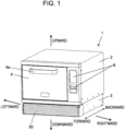
- FIG. 1 is a front perspective view of cooker 1 in the state where door 4 is closed.
- FIG. 2 is a front perspective view of cooker 1 in the state where door 4 is opened.
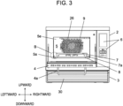
- FIG. 3 is a front view of cooker 1 in the state where door 4 is opened.
- the vertical upper side is defined as an upward direction
- a direction opposite to the upward direction is defined as a downward direction
- the right side and the left side of cooker 1 when viewed from a user are defined as a rightward direction and a leftward direction, respectively.
- a user side of cooker 1 is defined as a forward direction of cooker 1
- a direction opposite to the forward direction is defined as a backward direction of cooker 1.
- cooker 1 is a cooker for business use, i.e., a high-power cooker used in a convenience store, a fast-food restaurant, or the like.
- a cooker for home use i.e., a high-power cooker used in a convenience store, a fast-food restaurant, or the like.
- cooker 1 performs any of microwave heating, radiation heating, and hot-air circulation heating independently, or performs at least two of these sequentially or simultaneously.
- cooker 1 is provided with body 2, heating chamber 5, machine room 3, and door 4.
- Heating chamber 5 is provided inside body 2.
- Machine room 3 is disposed under heating chamber 5 in body 2.
- Door 4 is disposed in a front face of body 2 to cover an opening located in the front of heating chamber 5.
- Door 4 has handle 4a. When a user pulls handle 4a in the forward direction, door 4 is pivoted about a hinge, which is provided on both sides in a lower part thereof, and opened. In the front face of body 2, there is provided operation display 6 that displays setting operation, setting content, or the like for cooker 1 through a user. Detachable ventilation panel 30 is disposed in a front face of machine room 3.
- heating by microwave or the like is applied to a heating target in heating chamber 5.
- a heating target is accommodated in heating chamber 5, or taken out from heating chamber 5.
- Heating chamber 5 of body 2 is provided with a space of a substantially rectangular parallelepiped shape that includes an opening in the front thereof.
- Door 4 covers the opening in the front to seal heating chamber 5, so that a heating target to be cooked by heating is accommodated in heating chamber 5.
- a hot-air circulation heating mechanism, a radiation heating mechanism, or a microwave heating mechanism is used to cook the heating target by heating.
- the hot-air circulation heating mechanism is disposed behind heating chamber 5 and near a top face of heating chamber 5.
- the radiation heating mechanism is disposed near the top face of heating chamber 5.
- the microwave heating mechanism is disposed under bottom wall 5a of heating chamber 5.
- Bottom wall 5a of heating chamber 5 is made of a material through which microwave easily passes, such as glass or a ceramic, for example.
- placing table 7 and bottom plate 8 can be accommodated. Placing table 7 is used to place a heating target, and bottom plate 8 is disposed under placing table 7 to receive fat dripping from the heating target or the like.
- Placing table 7 can be detached out of heating chamber 5.
- Placing table 7 is constituted by a ceramic table, for example.
- Placing table 7 is integrally formed by a plate-like member capable of placing a heating target thereon and four legs 7a for supporting the plate-like member. Legs 7a are placed on bottom plate 8.
- the bottom plate 8 is fixed to an upper face of bottom wall 5a of heating chamber 5.
- Bottom plate 8 and placing table 7 are made of ceramic, specifically made of cordierite (cordierite).
- cordierite is a ceramic consisting of magnesium oxide, aluminum oxide, and silicon oxide, and has characteristics of low thermal expansion and excellent thermal shock resistance. Accordingly, if microwave concentrates on a surface of placing table 7, and even if a heating target is heated at a high temperature of 300°C or more, there will be no problem in the safety of placing table 7.
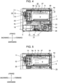
- FIG. 4 is a vertical cross-sectional view of a front center part of cooker 1 in the state where door 4 is closed.
- FIG. 5 is a partial cross-sectional view showing a flow of circulating air inside the cooker in the state where door 4 is closed.
- the right side indicates the forward direction of cooker 1.
- grill heater 9 which constitutes radiation heating portion 20, is disposed near the top face of heating chamber 5.
- Grill heater 9 is constituted by one sheath heater that is disposed near the top face and has a bent shape. Grill heater 9 is used in a grill mode (radiation heating) in which a heating target is cooked by heating using radiant heat.
- microwave heating portion 21 is disposed inside machine room 3.
- Microwave heating portion 21 includes magnetron 15, inverter 16, and cooling fan 17.
- Microwave heating portion 21 is controlled by a controller (not shown).
- Inverter 16 drives magnetron 15.
- Cooling fan 17 inhales air from ventilation panel 30, which is provided in the front face of machine room 3, and sends out the inhaled air to the back side. The air cools inverter 16, magnetron 15, and the like which are disposed inside machine room 3.
- Microwave heating portion 21 includes waveguide 18 and microwave supply portion 19.
- Waveguide 18 guides the microwave, which is generated by magnetron 15, to below the center part of heating chamber 5.
- the microwave supply portion 19 is an opening that is disposed below the center part of heating chamber 5 and formed in an upper face of an end part of waveguide 18.
- Microwave supply portion 19 emits the microwave, which is guided by the waveguide 18, to the inside of heating chamber 5.
- stirrer (stirrer) 23 is disposed above microwave supply portion 19.
- the stirrer driver is a motor disposed inside machine room 3.
- the stirred microwave is emitted to the inside of heating chamber 5 from under heating chamber 5, so that a heating target placed on placing table 7 is heated.
- cooker 1 is provided with hot-air generation mechanism 22, in addition to radiation heating portion 20 and microwave heating portion 21.
- Hot-air generation mechanism 22 is controlled by a controller (not shown) including a microcomputer.
- Hot-air generation mechanism 22, which is disposed inside body 2 and behind heating chamber 5, includes convection heater 10, circulation fan 11, and fan driver 12.
- Convection heater 10 is a heat source for hot-air circulation heating.
- Circulation fan 11 is an air blowing source.
- Fan driver 12 is a motor for driving circulation fan 11. As shown in FIGS. 2 and 3 , a plurality of holes 26 are formed in back wall 5e of heating chamber 5.
- Hot-air generation mechanism 22 includes flow passage forming portion 13 and air flow guide 14, which are described later.
- Flow passage forming portion 13 and air flow guide 14 are disposed in a part above heating chamber 5 to form a space above heating chamber 5, thereby specifying the flow velocity and the blowing direction of the air that flows inside the above space and is blown out to heating chamber 5.
- FIG. 6 is an enlarged cross-sectional view of B portion (see FIG. 3 ) in FIG. 3 .
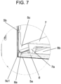
- FIG. 7 is an enlarged perspective view of A portion (see FIG. 2 ) in FIG. 2 .
- bottom plate 8 is fixed on bottom wall 5a of heating chamber 5.
- welding may be used, or adhesion by adhesives may be used, for example.
- Second inclination portion 8a which bulges upward from bottom plate 8 toward side plate 5c, is formed in right and left end parts (in FIGS. 6 and 7 , only a left end part is shown) of bottom plate 8.
- Side plate 5c is fixed to an inner surface of heating chamber 5 on side wall 5b of heating chamber 5.
- a lower end part of side plate 5c is bent to an inner side of heating chamber 5 to form first inclination portion 5c1.
- adhesion or welding, or a bolt and a nut may be used to perform the fixing. If a fluoride-coated plate material, which is made of stainless steel, is used for side plate 5c, dirt will hardly adhere to side plate 5c. Even if dirt adheres to side plate 5c, a user can easily clean it.
- Gap 5d exists between side wall 5b and bottom plate 8, as shown in FIG. 6 .
- First inclination portion 5c1 and second inclination portion 8a are in contact with each other such that first inclination portion 5c1 covers over second inclination portion 8a. In this way, first inclination portion 5c1 covers gap 5d and the right and left end parts of bottom plate 8.
- the lower end part of side plate 5c which is bent perpendicularly, may be brought into contact with a top part of bottom plate 8 to cover gap 5d and the end parts of bottom plate 8.
- bottom plate 8 is provided with recessed portion 8b that is formed in an upper face thereof, as shown in FIG. 7 .
- Placing table 7 has four legs 7a that can be placed in recessed portion 8b of bottom plate 8. With this structure, waterdrop, oil content, and the like, which are generated from a heating target, can efficiently be collected into recessed portion 8b of bottom plate 8 from placing table 7, thereby making it possible to reduce time and effort for a user to clean it.
- placing table 7 can be positioned easily. As long as placing table 7 is placed in recessed portion 8b of bottom plate 8, the number of legs 7a may be a number other than four.
- the structure of the lower right corner of heating chamber 5 is the same as that of the lower left corner thereof. However, these corners may have different structures from each other.
- the present disclosure is applicable to a microwave oven, a toaster oven, and the like, for example.
Landscapes
- Engineering & Computer Science (AREA)
- Chemical & Material Sciences (AREA)
- Combustion & Propulsion (AREA)
- Mechanical Engineering (AREA)
- General Engineering & Computer Science (AREA)
- Physics & Mathematics (AREA)
- Electromagnetism (AREA)
- Electric Ovens (AREA)
Abstract
Description
- The present disclosure relates to a cooker.
- In the conventional cooker, a gap between a side wall and a bottom wall of a heat chamber is filled with adhesive glue or the like to prevent steam, waterdrop, oil content, and the like, which are generated in the heat chamber, from leaking out of the heat chamber (see Patent Literature 1).
- PTL 1: Unexamined
Japanese Patent Publication No.2020-139707 - In the conventional cooker, there is still room for improvement in the viewpoint of collecting waterdrop, oil content, and the like, which are generated in the heating chamber, in a bottom plate of a heating chamber efficiently.
- The present disclosure aims to provide a cooker capable of collecting waterdrop, oil content, and the like, which are generated in the heating chamber, in the bottom plate of the heating chamber efficiently.
- A cooker in accordance with one aspect of the present disclosure is provided with a body, a heating chamber, a microwave heating mechanism, and a door. The heating chamber, which is provided inside the body, includes a bottom wall and a side wall. The microwave heating mechanism emits microwave to the heating chamber. The door is attached to the body to cover an opening of the heating chamber. The heating chamber further includes a bottom plate that is disposed above the bottom wall and separated from the side wall by a gap, and a side plate that is disposed on an inner surface of the heating chamber of the side wall to cover the gap and a part of the bottom plate.
- According to the present disclosure, waterdrop, oil content, and the like, which are generated in the heating chamber, can efficiently be collected in the bottom plate of the heating chamber.
-
-
FIG. 1 is a front perspective view of a cooker in accordance with an exemplary embodiment of the present disclosure. -
FIG. 2 is a front perspective view of the cooker in accordance with the exemplary embodiment in the state where a door is opened. -
FIG. 3 is a front view of the cooker in accordance with the exemplary embodiment in the state where the door is opened. -
FIG. 4 is a vertical cross-sectional view of the front center of the cooker in accordance with the exemplary embodiment in the state where the door is closed. -
FIG. 5 is a partial cross-sectional view showing a flow of circulating air inside the cooker in accordance with the exemplary embodiment in the state where the door is closed. -
FIG. 6 is a partially enlarged cross-sectional view of the cooker in accordance with the exemplary embodiment. -
FIG. 7 is a partially enlarged perspective view of the cooker in accordance with the exemplary embodiment. - The inventors of the present application have made extensive studied to collect waterdrop, oil content, and the like, which are generated in a heating chamber, in a bottom plate of the heating chamber efficiently. As the result, they have obtained the following knowledge.
- In the conventional cooker, a gap between a side wall and a bottom wall of the heating chamber is filled with adhesive glue or the like to prevent steam, waterdrop, oil content, and the like, which are generated in the heating chamber, from leaking out of the heating chamber.
- However, if a bottom plate, which can withstand heating by a 1500W high-power heater and a high-power microwave, is installed above the bottom wall of the heating chamber, a gap may be generated between the bottom plate and the side wall of the heating chamber. If waterdrop, oil content, food scraps, and the like enter this gap, the cleaning will be made difficult to cause hygienic problems.
- If the gap between the bottom plate and the side wall of the heating chamber is covered with a side plate, waterdrop, oil content, and the like, which are generated in the heating chamber, can efficiently be collected in the bottom plate of the heating chamber. As a result, waterdrop, oil content, food scraps, and the like can be prevented from entering this gap, thereby making it possible to reduce time and effort for a user to clean it. Based on this knowledge, the inventors of the present application have reached the following invention.
- A cooker in accordance with a first aspect of the present disclosure is provided with a body, a heating chamber, a microwave heating mechanism, and a door. The heating chamber, which is provided inside the body, includes a bottom wall and a side wall. The microwave heating mechanism emits microwave to the heating chamber. The door is attached to the body to cover an opening of the heating chamber. The heating chamber further includes a bottom plate that is disposed above the bottom wall and separated from the side wall by a gap, and a side plate that is disposed on an inner surface of the heating chamber of the side wall to cover the gap and a part of the bottom plate.
- According to the aspect, waterdrop, oil content, and the like, which are generated in the heating chamber, can efficiently be collected in the bottom plate of the heating chamber from the side plate of the heating chamber. Waterdrop, oil content, food scraps, and the like can be prevented from entering this gap, thereby making it possible to reduce time and effort for a user to clean it.
- In a cooker in accordance with a second aspect of the present disclosure, in addition to the first aspect, the side plate includes a first inclination portion provided in a lower end part of the side plate, and the bottom plate includes a second inclination portion provided in an end part of the bottom plate facing the gap. Herein, the first inclination portion is in contact with the second inclination portion so as to cover the gap.
- According to this aspect, waterdrop, oil content, and the like, which are generated in the heating chamber, can efficiently be collected in the bottom plate of the heating chamber from the inclined end portion of the side plate in the heating chamber. Waterdrop, oil content, food scraps, and the like can be prevented from entering this gap, thereby making it possible to reduce time and effort for a user to clean it.
- In a cooker in accordance with a third aspect of the present disclosure, the bottom plate further includes a recessed portion provided in an upper face thereof, in addition to the first aspect or the second aspect.
- According to this aspect, waterdrop, oil content, and the like, which are generated in the heating chamber, can be collected into the recessed portion provided in the upper face of the bottom plate in the heating chamber from the side plate of the heating chamber, thereby making it possible to reduce time and effort for a user to clean it.
- In addition to the third aspect, a cooker in accordance with a fourth aspect of the present disclosure is further provided with a placing table having a leg that can be placed in the recessed portion.
- According to this aspect, waterdrop, oil content, and the like, which are generated from a heating target, can efficiently be collected into the recessed portion of the bottom plate from the placing table, thereby making it possible to reduce time and effort for a user to clean it.
- Hereinafter,
cooker 1 in accordance with an exemplary embodiment of the present disclosure will be described with reference to the drawings.FIG. 1 is a front perspective view ofcooker 1 in the state wheredoor 4 is closed.FIG. 2 is a front perspective view ofcooker 1 in the state wheredoor 4 is opened.FIG. 3 is a front view ofcooker 1 in the state wheredoor 4 is opened. - In the present exemplary embodiment, as shown in each view, the vertical upper side is defined as an upward direction, a direction opposite to the upward direction is defined as a downward direction, and the right side and the left side of
cooker 1 when viewed from a user are defined as a rightward direction and a leftward direction, respectively. When a user uses the cooker, a user side ofcooker 1 is defined as a forward direction ofcooker 1, and a direction opposite to the forward direction is defined as a backward direction ofcooker 1. - In the present exemplary embodiment,
cooker 1 is a cooker for business use, i.e., a high-power cooker used in a convenience store, a fast-food restaurant, or the like. Of course, the present disclosure is also applicable to a cooker for home use. According to a cooking content,cooker 1 performs any of microwave heating, radiation heating, and hot-air circulation heating independently, or performs at least two of these sequentially or simultaneously. - As shown in
FIGS. 1 through 3 ,cooker 1 is provided withbody 2,heating chamber 5,machine room 3, anddoor 4.Heating chamber 5 is provided insidebody 2.Machine room 3 is disposed underheating chamber 5 inbody 2.Door 4 is disposed in a front face ofbody 2 to cover an opening located in the front ofheating chamber 5. - Door 4 has
handle 4a. When a user pulls handle 4a in the forward direction,door 4 is pivoted about a hinge, which is provided on both sides in a lower part thereof, and opened. In the front face ofbody 2, there is providedoperation display 6 that displays setting operation, setting content, or the like forcooker 1 through a user.Detachable ventilation panel 30 is disposed in a front face ofmachine room 3. - In the state where
door 4 is closed (seeFIG. 1 ), heating by microwave or the like is applied to a heating target inheating chamber 5. In the state wheredoor 4 is opened (seeFIG. 2 ), a heating target is accommodated inheating chamber 5, or taken out fromheating chamber 5. -
Heating chamber 5 ofbody 2 is provided with a space of a substantially rectangular parallelepiped shape that includes an opening in the front thereof.Door 4 covers the opening in the front to sealheating chamber 5, so that a heating target to be cooked by heating is accommodated inheating chamber 5. In this state, at least one of a hot-air circulation heating mechanism, a radiation heating mechanism, or a microwave heating mechanism is used to cook the heating target by heating. - The hot-air circulation heating mechanism is disposed behind
heating chamber 5 and near a top face ofheating chamber 5. The radiation heating mechanism is disposed near the top face ofheating chamber 5. The microwave heating mechanism is disposed underbottom wall 5a ofheating chamber 5.Bottom wall 5a ofheating chamber 5 is made of a material through which microwave easily passes, such as glass or a ceramic, for example. - Inside
heating chamber 5, placing table 7 andbottom plate 8 can be accommodated. Placing table 7 is used to place a heating target, andbottom plate 8 is disposed under placing table 7 to receive fat dripping from the heating target or the like. - Placing table 7 can be detached out of
heating chamber 5. Placing table 7 is constituted by a ceramic table, for example. Placing table 7 is integrally formed by a plate-like member capable of placing a heating target thereon and fourlegs 7a for supporting the plate-like member.Legs 7a are placed onbottom plate 8. Thebottom plate 8 is fixed to an upper face ofbottom wall 5a ofheating chamber 5. -
Bottom plate 8 and placing table 7 are made of ceramic, specifically made of cordierite (cordierite). The cordierite is a ceramic consisting of magnesium oxide, aluminum oxide, and silicon oxide, and has characteristics of low thermal expansion and excellent thermal shock resistance. Accordingly, if microwave concentrates on a surface of placing table 7, and even if a heating target is heated at a high temperature of 300°C or more, there will be no problem in the safety of placing table 7. -
FIG. 4 is a vertical cross-sectional view of a front center part ofcooker 1 in the state wheredoor 4 is closed.FIG. 5 is a partial cross-sectional view showing a flow of circulating air inside the cooker in the state wheredoor 4 is closed. InFIGS. 4 and 5 , the right side indicates the forward direction ofcooker 1. - As shown in
FIGS. 4 and 5 ,grill heater 9, which constitutesradiation heating portion 20, is disposed near the top face ofheating chamber 5.Grill heater 9 is constituted by one sheath heater that is disposed near the top face and has a bent shape.Grill heater 9 is used in a grill mode (radiation heating) in which a heating target is cooked by heating using radiant heat. - As shown in
FIG. 4 ,microwave heating portion 21 is disposed insidemachine room 3.Microwave heating portion 21 includesmagnetron 15,inverter 16, and coolingfan 17.Microwave heating portion 21 is controlled by a controller (not shown). - The magnetron generates microwave.
Inverter 16drives magnetron 15. Coolingfan 17 inhales air fromventilation panel 30, which is provided in the front face ofmachine room 3, and sends out the inhaled air to the back side. The air coolsinverter 16,magnetron 15, and the like which are disposed insidemachine room 3. -
Microwave heating portion 21 includeswaveguide 18 andmicrowave supply portion 19.Waveguide 18 guides the microwave, which is generated bymagnetron 15, to below the center part ofheating chamber 5. Themicrowave supply portion 19 is an opening that is disposed below the center part ofheating chamber 5 and formed in an upper face of an end part ofwaveguide 18.Microwave supply portion 19 emits the microwave, which is guided by thewaveguide 18, to the inside ofheating chamber 5. - To stir the microwave emitted from
microwave supply portion 19, stirrer (stirrer) 23 is disposed abovemicrowave supply portion 19.Stirrer 23, which is driven by a stirrer driver (not shown), includes a blade for stirring the microwave emitted frommicrowave supply portion 19. The stirrer driver is a motor disposed insidemachine room 3. - Accordingly, in
cooker 1, the stirred microwave is emitted to the inside ofheating chamber 5 from underheating chamber 5, so that a heating target placed on placing table 7 is heated. - As shown in
FIGS. 4 and 5 ,cooker 1 is provided with hot-air generation mechanism 22, in addition toradiation heating portion 20 andmicrowave heating portion 21. Hot-air generation mechanism 22 is controlled by a controller (not shown) including a microcomputer. Hot-air generation mechanism 22, which is disposed insidebody 2 and behindheating chamber 5, includesconvection heater 10,circulation fan 11, andfan driver 12. -
Convection heater 10 is a heat source for hot-air circulation heating.Circulation fan 11 is an air blowing source.Fan driver 12 is a motor for drivingcirculation fan 11. As shown inFIGS. 2 and3 , a plurality ofholes 26 are formed inback wall 5e ofheating chamber 5. - When
circulation fan 11 is operated, the air inheating chamber 5 is inhaled throughholes 26 and reaches hot-air generation mechanism 22. In hot-air generation mechanism 22, the air is converted into hot air throughconvection heater 10 andcirculation fan 11. The hot air is blown out to the inside ofheating chamber 5 fromair outlet 27 provided in a bottom face of flowpassage forming portion 13. Outline arrows inFIG. 5 indicate a flow of the air insidecooker 1. - Hot-
air generation mechanism 22 includes flowpassage forming portion 13 andair flow guide 14, which are described later. Flowpassage forming portion 13 andair flow guide 14, which are disposed near the top face ofheating chamber 5, specify a flow velocity and a blowing direction of the air flowing fromair outlet 27 toheating chamber 5. - Flow
passage forming portion 13 andair flow guide 14 are disposed in a part aboveheating chamber 5 to form a space aboveheating chamber 5, thereby specifying the flow velocity and the blowing direction of the air that flows inside the above space and is blown out toheating chamber 5. - Next, the structure of
bottom wall 5a andside wall 5b in a lower left corner and a lower right corner ofheating chamber 5 will be described.FIG. 6 is an enlarged cross-sectional view of B portion (seeFIG. 3 ) inFIG. 3 .FIG. 7 is an enlarged perspective view of A portion (seeFIG. 2 ) inFIG. 2 . - As shown in
FIGS. 6 and7 ,bottom plate 8 is fixed onbottom wall 5a ofheating chamber 5. As a method of fixingbottom plate 8, welding may be used, or adhesion by adhesives may be used, for example.Second inclination portion 8a, which bulges upward frombottom plate 8 towardside plate 5c, is formed in right and left end parts (inFIGS. 6 and7 , only a left end part is shown) ofbottom plate 8. -
Side plate 5c is fixed to an inner surface ofheating chamber 5 onside wall 5b ofheating chamber 5. A lower end part ofside plate 5c is bent to an inner side ofheating chamber 5 to form first inclination portion 5c1. As a method of fixingside plate 5c toside wall 5b, adhesion or welding, or a bolt and a nut may be used to perform the fixing. If a fluoride-coated plate material, which is made of stainless steel, is used forside plate 5c, dirt will hardly adhere toside plate 5c. Even if dirt adheres toside plate 5c, a user can easily clean it. -
Gap 5d exists betweenside wall 5b andbottom plate 8, as shown inFIG. 6 . First inclination portion 5c1 andsecond inclination portion 8a are in contact with each other such that first inclination portion 5c1 covers oversecond inclination portion 8a. In this way, first inclination portion 5c1 coversgap 5d and the right and left end parts ofbottom plate 8. - Besides the above-mentioned method, the lower end part of
side plate 5c, which is bent perpendicularly, may be brought into contact with a top part ofbottom plate 8 to covergap 5d and the end parts ofbottom plate 8. - With such structure, waterdrop, oil content, and the like, which are generated in
heating chamber 5, can efficiently be collected inbottom plate 8 ofheating chamber 5 fromside plate 5c ofheating chamber 5. Thus, waterdrop, oil content, food scraps, and the like can be prevented from enteringgap 5d, thereby making it possible to reduce time and effort for a user to clean it. - Furthermore,
bottom plate 8 is provided with recessedportion 8b that is formed in an upper face thereof, as shown inFIG. 7 . With this structure, waterdrop, oil content, and the like, which are generated in the heating chamber, can efficiently be collected into recessedportion 8b ofbottom plate 8 inheating chamber 5 fromside plate 5c ofheating chamber 5, thereby making it possible to reduce time and effort for a user to clean it. - Placing table 7 has four
legs 7a that can be placed in recessedportion 8b ofbottom plate 8. With this structure, waterdrop, oil content, and the like, which are generated from a heating target, can efficiently be collected into recessedportion 8b ofbottom plate 8 from placing table 7, thereby making it possible to reduce time and effort for a user to clean it. - Further, if four
legs 7a each are disposed so as to be brought into contact with a corresponding one of four corners of recessedportion 8b, placing table 7 can be positioned easily. As long as placing table 7 is placed in recessedportion 8b ofbottom plate 8, the number oflegs 7a may be a number other than four. - Note that, in the present exemplary embodiment, the structure of the lower right corner of
heating chamber 5 is the same as that of the lower left corner thereof. However, these corners may have different structures from each other. - The present disclosure is applicable to a microwave oven, a toaster oven, and the like, for example.
-
- 1
- cooker
- 2
- body
- 3
- machine room
- 4
- door
- 4a
- handle
- 5
- heating chamber
- 5a
- bottom wall
- 5b
- side wall
- 5c
- side plate
- 5c1
- first inclination portion
- 5d
- gap
- 5e
- back wall
- 6
- operation display
- 7
- placing table
- 7a
- leg
- 8
- bottom plate
- 8a
- second inclination portion
- 8b
- recessed portion
- 9
- grill heater
- 10
- convection heater
- 11
- circulation fan
- 12
- fan driver
- 13
- flow passage forming portion
- 14
- air flow guide
- 15
- magnetron
- 16
- inverter
- 17
- cooling fan
- 18
- waveguide
- 19
- microwave supply portion
- 20
- radiation heating portion
- 21
- microwave heating portion
- 22
- hot-air generation mechanism
- 23
- stirrer
- 26
- hole
- 27
- air outlet
- 30
- ventilation panel
Claims (4)
- A cooker comprising:a body;a heating chamber that includes a bottom wall and a side wall, the heating chamber being provided inside the body;a microwave heating mechanism that is configured to emit microwave to the heating chamber; anda door that is attached to the body to cover an opening of the heating chamber,whereinthe heating chamber further includesa bottom plate that is disposed above the bottom wall and separated from the side wall by a gap, anda side plate that is disposed on an inner surface of the heating chamber of the side wall to cover the gap and a part of the bottom plate.
- The cooker according to claim 1, whereinthe side plate includes a first inclination portion provided in a lower end part of the side plate,the bottom plate includes a second inclination portion provided in an end part of the bottom plate facing the gap, andthe first inclination portion is in contact with the second inclination portion so as to cover the gap.
- The cooker according to claim 1 or 2, wherein
the bottom plate further includes a recessed portion provided in an upper face of the bottom plate. - The cooker according to claim 3, further comprising
a placing table that includes a leg allowed to be placed in the recessed portion.
Applications Claiming Priority (2)
| Application Number | Priority Date | Filing Date | Title |
|---|---|---|---|
| JP2021163188A JP7607199B2 (en) | 2021-10-04 | 2021-10-04 | Cooking equipment |
| PCT/JP2022/034882 WO2023058444A1 (en) | 2021-10-04 | 2022-09-20 | Heating cooker |
Publications (3)
| Publication Number | Publication Date |
|---|---|
| EP4414615A1 true EP4414615A1 (en) | 2024-08-14 |
| EP4414615A4 EP4414615A4 (en) | 2025-01-22 |
| EP4414615B1 EP4414615B1 (en) | 2025-10-29 |
Family
ID=85804219
Family Applications (1)
| Application Number | Title | Priority Date | Filing Date |
|---|---|---|---|
| EP22878315.5A Active EP4414615B1 (en) | 2021-10-04 | 2022-09-20 | Heating cooker |
Country Status (5)
| Country | Link |
|---|---|
| US (1) | US20240344707A1 (en) |
| EP (1) | EP4414615B1 (en) |
| JP (1) | JP7607199B2 (en) |
| CN (1) | CN117795254A (en) |
| WO (1) | WO2023058444A1 (en) |
Family Cites Families (9)
| Publication number | Priority date | Publication date | Assignee | Title |
|---|---|---|---|---|
| JPS4928858Y1 (en) * | 1969-12-29 | 1974-08-06 | ||
| JPH07301429A (en) * | 1994-05-02 | 1995-11-14 | Matsushita Electric Ind Co Ltd | Heating cooker |
| JP2005230162A (en) | 2004-02-18 | 2005-09-02 | Osaka Gas Co Ltd | Cooker |
| JP4964175B2 (en) | 2008-03-10 | 2012-06-27 | 三菱電機株式会社 | Cooker |
| JP5137660B2 (en) * | 2008-03-31 | 2013-02-06 | 三菱電機株式会社 | Cooker |
| US20110084065A1 (en) * | 2009-10-09 | 2011-04-14 | Charles Gibson | Slidable Tray Assembly for Microwave Oven |
| US8997730B2 (en) * | 2011-11-29 | 2015-04-07 | Alto-Shaam, Inc. | Grease handling apparatus for closed system oven |
| EP3343110B1 (en) * | 2015-08-26 | 2019-10-23 | Panasonic Intellectual Property Management Co., Ltd. | Cooker |
| JP2020139707A (en) | 2019-02-28 | 2020-09-03 | パナソニックIpマネジメント株式会社 | Cooker |
-
2021
- 2021-10-04 JP JP2021163188A patent/JP7607199B2/en active Active
-
2022
- 2022-09-20 WO PCT/JP2022/034882 patent/WO2023058444A1/en not_active Ceased
- 2022-09-20 CN CN202280054236.6A patent/CN117795254A/en active Pending
- 2022-09-20 US US18/579,657 patent/US20240344707A1/en active Pending
- 2022-09-20 EP EP22878315.5A patent/EP4414615B1/en active Active
Also Published As
| Publication number | Publication date |
|---|---|
| WO2023058444A1 (en) | 2023-04-13 |
| CN117795254A (en) | 2024-03-29 |
| JP2023054384A (en) | 2023-04-14 |
| EP4414615B1 (en) | 2025-10-29 |
| JP7607199B2 (en) | 2024-12-27 |
| EP4414615A4 (en) | 2025-01-22 |
| US20240344707A1 (en) | 2024-10-17 |
Similar Documents
| Publication | Publication Date | Title |
|---|---|---|
| US7762250B2 (en) | Cooking appliance having a latch plate shield for improved guidance of cooling air and exhaust air | |
| US7708008B2 (en) | Double oven combination with an integrated cooling air and exhaust air flow arrangement | |
| CA2618943C (en) | Oven with oven door having an air deflection assembly | |
| US20080184984A1 (en) | Oven door assembly having shield for drawing heat away from an oven door window | |
| CN102239365B (en) | Hobs with forced convection cooling | |
| EP1586820B1 (en) | Cooling apparatus of cooking appliance | |
| JP4115889B2 (en) | Built-in cooker | |
| JP5744496B2 (en) | Cooker | |
| CN111520775B (en) | Heating cooker | |
| EP4414615B1 (en) | Heating cooker | |
| JP5947951B2 (en) | Cooker | |
| WO2018062063A1 (en) | Heat-cooking appliance | |
| US20240344706A1 (en) | Heating cooker | |
| JP5595174B2 (en) | Cooker | |
| JP2007003042A (en) | Cooker | |
| KR102853490B1 (en) | A oven range | |
| JPH0311233A (en) | High frequency heating device with heater | |
| EP1972856B1 (en) | Cooking appliance | |
| JP4342221B2 (en) | Built-in cooker | |
| JP2011058674A (en) | Cooker | |
| JP2015094507A (en) | Heating cooker | |
| KR20250159540A (en) | Cooking apparatus | |
| KR20250090138A (en) | Cooking apparatus | |
| KR20090050475A (en) | Cooker | |
| CN116211140A (en) | cooking utensils |
Legal Events
| Date | Code | Title | Description |
|---|---|---|---|
| STAA | Information on the status of an ep patent application or granted ep patent |
Free format text: STATUS: THE INTERNATIONAL PUBLICATION HAS BEEN MADE |
|
| PUAI | Public reference made under article 153(3) epc to a published international application that has entered the european phase |
Free format text: ORIGINAL CODE: 0009012 |
|
| STAA | Information on the status of an ep patent application or granted ep patent |
Free format text: STATUS: REQUEST FOR EXAMINATION WAS MADE |
|
| 17P | Request for examination filed |
Effective date: 20240215 |
|
| AK | Designated contracting states |
Kind code of ref document: A1 Designated state(s): AL AT BE BG CH CY CZ DE DK EE ES FI FR GB GR HR HU IE IS IT LI LT LU LV MC MK MT NL NO PL PT RO RS SE SI SK SM TR |
|
| REG | Reference to a national code |
Ref country code: DE Ref legal event code: R079 Free format text: PREVIOUS MAIN CLASS: F24C0007020000 Ipc: H05B0006640000 Ref document number: 602022024182 Country of ref document: DE |
|
| DAV | Request for validation of the european patent (deleted) | ||
| DAX | Request for extension of the european patent (deleted) | ||
| A4 | Supplementary search report drawn up and despatched |
Effective date: 20241220 |
|
| RIC1 | Information provided on ipc code assigned before grant |
Ipc: F24C 15/14 20060101ALI20241216BHEP Ipc: F24C 15/08 20060101ALI20241216BHEP Ipc: F24C 15/00 20060101ALI20241216BHEP Ipc: F24C 7/02 20060101ALI20241216BHEP Ipc: H05B 6/64 20060101AFI20241216BHEP |
|
| GRAP | Despatch of communication of intention to grant a patent |
Free format text: ORIGINAL CODE: EPIDOSNIGR1 |
|
| STAA | Information on the status of an ep patent application or granted ep patent |
Free format text: STATUS: GRANT OF PATENT IS INTENDED |
|
| INTG | Intention to grant announced |
Effective date: 20250612 |
|
| GRAS | Grant fee paid |
Free format text: ORIGINAL CODE: EPIDOSNIGR3 |
|
| GRAA | (expected) grant |
Free format text: ORIGINAL CODE: 0009210 |
|
| STAA | Information on the status of an ep patent application or granted ep patent |
Free format text: STATUS: THE PATENT HAS BEEN GRANTED |
|
| AK | Designated contracting states |
Kind code of ref document: B1 Designated state(s): AL AT BE BG CH CY CZ DE DK EE ES FI FR GB GR HR HU IE IS IT LI LT LU LV MC MK MT NL NO PL PT RO RS SE SI SK SM TR |
|
| REG | Reference to a national code |
Ref country code: CH Ref legal event code: F10 Free format text: ST27 STATUS EVENT CODE: U-0-0-F10-F00 (AS PROVIDED BY THE NATIONAL OFFICE) Effective date: 20251029 Ref country code: GB Ref legal event code: FG4D |
|
| REG | Reference to a national code |
Ref country code: DE Ref legal event code: R096 Ref document number: 602022024182 Country of ref document: DE |
|
| REG | Reference to a national code |
Ref country code: IE Ref legal event code: FG4D |
|
| REG | Reference to a national code |
Ref country code: NL Ref legal event code: MP Effective date: 20251029 |
|
| PG25 | Lapsed in a contracting state [announced via postgrant information from national office to epo] |
Ref country code: ES Free format text: LAPSE BECAUSE OF FAILURE TO SUBMIT A TRANSLATION OF THE DESCRIPTION OR TO PAY THE FEE WITHIN THE PRESCRIBED TIME-LIMIT Effective date: 20251029 |
|
| REG | Reference to a national code |
Ref country code: LT Ref legal event code: MG9D |
|
| PG25 | Lapsed in a contracting state [announced via postgrant information from national office to epo] |
Ref country code: NO Free format text: LAPSE BECAUSE OF FAILURE TO SUBMIT A TRANSLATION OF THE DESCRIPTION OR TO PAY THE FEE WITHIN THE PRESCRIBED TIME-LIMIT Effective date: 20260129 |
|
| PG25 | Lapsed in a contracting state [announced via postgrant information from national office to epo] |
Ref country code: AT Free format text: LAPSE BECAUSE OF FAILURE TO SUBMIT A TRANSLATION OF THE DESCRIPTION OR TO PAY THE FEE WITHIN THE PRESCRIBED TIME-LIMIT Effective date: 20251029 Ref country code: HR Free format text: LAPSE BECAUSE OF FAILURE TO SUBMIT A TRANSLATION OF THE DESCRIPTION OR TO PAY THE FEE WITHIN THE PRESCRIBED TIME-LIMIT Effective date: 20251029 Ref country code: FI Free format text: LAPSE BECAUSE OF FAILURE TO SUBMIT A TRANSLATION OF THE DESCRIPTION OR TO PAY THE FEE WITHIN THE PRESCRIBED TIME-LIMIT Effective date: 20251029 |
|
| REG | Reference to a national code |
Ref country code: AT Ref legal event code: MK05 Ref document number: 1853190 Country of ref document: AT Kind code of ref document: T Effective date: 20251029 |
|
| PG25 | Lapsed in a contracting state [announced via postgrant information from national office to epo] |
Ref country code: NL Free format text: LAPSE BECAUSE OF FAILURE TO SUBMIT A TRANSLATION OF THE DESCRIPTION OR TO PAY THE FEE WITHIN THE PRESCRIBED TIME-LIMIT Effective date: 20251029 |
|
| PG25 | Lapsed in a contracting state [announced via postgrant information from national office to epo] |
Ref country code: RS Free format text: LAPSE BECAUSE OF FAILURE TO SUBMIT A TRANSLATION OF THE DESCRIPTION OR TO PAY THE FEE WITHIN THE PRESCRIBED TIME-LIMIT Effective date: 20260129 |
|
| PG25 | Lapsed in a contracting state [announced via postgrant information from national office to epo] |
Ref country code: IS Free format text: LAPSE BECAUSE OF FAILURE TO SUBMIT A TRANSLATION OF THE DESCRIPTION OR TO PAY THE FEE WITHIN THE PRESCRIBED TIME-LIMIT Effective date: 20260228 |
|
| PG25 | Lapsed in a contracting state [announced via postgrant information from national office to epo] |
Ref country code: PT Free format text: LAPSE BECAUSE OF FAILURE TO SUBMIT A TRANSLATION OF THE DESCRIPTION OR TO PAY THE FEE WITHIN THE PRESCRIBED TIME-LIMIT Effective date: 20260302 |
|
| PG25 | Lapsed in a contracting state [announced via postgrant information from national office to epo] |
Ref country code: PL Free format text: LAPSE BECAUSE OF FAILURE TO SUBMIT A TRANSLATION OF THE DESCRIPTION OR TO PAY THE FEE WITHIN THE PRESCRIBED TIME-LIMIT Effective date: 20251029 |
|
| PG25 | Lapsed in a contracting state [announced via postgrant information from national office to epo] |
Ref country code: LV Free format text: LAPSE BECAUSE OF FAILURE TO SUBMIT A TRANSLATION OF THE DESCRIPTION OR TO PAY THE FEE WITHIN THE PRESCRIBED TIME-LIMIT Effective date: 20251029 |