EP4414304A1 - Elevator machine braking - Google Patents
Elevator machine braking Download PDFInfo
- Publication number
- EP4414304A1 EP4414304A1 EP24155571.3A EP24155571A EP4414304A1 EP 4414304 A1 EP4414304 A1 EP 4414304A1 EP 24155571 A EP24155571 A EP 24155571A EP 4414304 A1 EP4414304 A1 EP 4414304A1
- Authority
- EP
- European Patent Office
- Prior art keywords
- storage device
- energy storage
- motor
- converter switches
- elevator
- Prior art date
- Legal status (The legal status is an assumption and is not a legal conclusion. Google has not performed a legal analysis and makes no representation as to the accuracy of the status listed.)
- Granted
Links
Images


Classifications
-
- B—PERFORMING OPERATIONS; TRANSPORTING
- B66—HOISTING; LIFTING; HAULING
- B66B—ELEVATORS; ESCALATORS OR MOVING WALKWAYS
- B66B1/00—Control systems of elevators in general
- B66B1/24—Control systems with regulation, i.e. with retroactive action, for influencing travelling speed, acceleration, or deceleration
- B66B1/28—Control systems with regulation, i.e. with retroactive action, for influencing travelling speed, acceleration, or deceleration electrical
- B66B1/30—Control systems with regulation, i.e. with retroactive action, for influencing travelling speed, acceleration, or deceleration electrical effective on driving gear, e.g. acting on power electronics, on inverter or rectifier controlled motor
- B66B1/302—Control systems with regulation, i.e. with retroactive action, for influencing travelling speed, acceleration, or deceleration electrical effective on driving gear, e.g. acting on power electronics, on inverter or rectifier controlled motor for energy saving
-
- H—ELECTRICITY
- H02—GENERATION; CONVERSION OR DISTRIBUTION OF ELECTRIC POWER
- H02P—CONTROL OR REGULATION OF ELECTRIC MOTORS, ELECTRIC GENERATORS OR DYNAMO-ELECTRIC CONVERTERS; CONTROLLING TRANSFORMERS, REACTORS OR CHOKE COILS
- H02P3/00—Arrangements for stopping or slowing electric motors, generators, or dynamo-electric converters
- H02P3/06—Arrangements for stopping or slowing electric motors, generators, or dynamo-electric converters for stopping or slowing an individual dynamo-electric motor or dynamo-electric converter
- H02P3/18—Arrangements for stopping or slowing electric motors, generators, or dynamo-electric converters for stopping or slowing an individual dynamo-electric motor or dynamo-electric converter for stopping or slowing an AC motor
- H02P3/22—Arrangements for stopping or slowing electric motors, generators, or dynamo-electric converters for stopping or slowing an individual dynamo-electric motor or dynamo-electric converter for stopping or slowing an AC motor by short-circuit or resistive braking
-
- B—PERFORMING OPERATIONS; TRANSPORTING
- B66—HOISTING; LIFTING; HAULING
- B66B—ELEVATORS; ESCALATORS OR MOVING WALKWAYS
- B66B11/00—Main component parts of lifts in, or associated with, buildings or other structures
- B66B11/04—Driving gear ; Details thereof, e.g. seals
- B66B11/043—Driving gear ; Details thereof, e.g. seals actuated by rotating motor; Details, e.g. ventilation
-
- B—PERFORMING OPERATIONS; TRANSPORTING
- B66—HOISTING; LIFTING; HAULING
- B66B—ELEVATORS; ESCALATORS OR MOVING WALKWAYS
- B66B1/00—Control systems of elevators in general
- B66B1/02—Control systems without regulation, i.e. without retroactive action
- B66B1/06—Control systems without regulation, i.e. without retroactive action electric
-
- B—PERFORMING OPERATIONS; TRANSPORTING
- B66—HOISTING; LIFTING; HAULING
- B66B—ELEVATORS; ESCALATORS OR MOVING WALKWAYS
- B66B1/00—Control systems of elevators in general
- B66B1/24—Control systems with regulation, i.e. with retroactive action, for influencing travelling speed, acceleration, or deceleration
- B66B1/28—Control systems with regulation, i.e. with retroactive action, for influencing travelling speed, acceleration, or deceleration electrical
- B66B1/30—Control systems with regulation, i.e. with retroactive action, for influencing travelling speed, acceleration, or deceleration electrical effective on driving gear, e.g. acting on power electronics, on inverter or rectifier controlled motor
- B66B1/308—Control systems with regulation, i.e. with retroactive action, for influencing travelling speed, acceleration, or deceleration electrical effective on driving gear, e.g. acting on power electronics, on inverter or rectifier controlled motor with AC powered elevator drive
-
- B—PERFORMING OPERATIONS; TRANSPORTING
- B66—HOISTING; LIFTING; HAULING
- B66B—ELEVATORS; ESCALATORS OR MOVING WALKWAYS
- B66B1/00—Control systems of elevators in general
- B66B1/34—Details, e.g. call counting devices, data transmission from car to control system, devices giving information to the control system
-
- B—PERFORMING OPERATIONS; TRANSPORTING
- B66—HOISTING; LIFTING; HAULING
- B66D—CAPSTANS; WINCHES; TACKLES, e.g. PULLEY BLOCKS; HOISTS
- B66D5/00—Braking or detent devices characterised by application to lifting or hoisting gear, e.g. for controlling the lowering of loads
- B66D5/02—Crane, lift hoist, or winch brakes operating on drums, barrels, or ropes
-
- H—ELECTRICITY
- H02—GENERATION; CONVERSION OR DISTRIBUTION OF ELECTRIC POWER
- H02J—ELECTRIC POWER NETWORKS; CIRCUIT ARRANGEMENTS OR SYSTEMS FOR SUPPLYING OR DISTRIBUTING ELECTRIC POWER; SYSTEMS FOR STORING ELECTRIC ENERGY
- H02J3/00—Circuit arrangements for AC mains or AC distribution networks
- H02J3/28—Arrangements for balancing of the load in networks by storage of energy
- H02J3/32—Arrangements for balancing of the load in networks by storage of energy using batteries or super capacitors with converting means
Definitions
- Elevator systems are in widespread use for carrying passengers between various levels in buildings, for example.
- Some elevator systems are traction-based in which roping that suspends the elevator car and a counterweight facilitates movement of the elevator car when needed.
- the roping moves in response to movement of a traction sheave, which is driven by a machine motor or prevented from rotating by a machine brake. In most situations, the machine brake is applied or dropped to stop the elevator car.
- Alternative or additional ways of braking movement of the elevator car at the machine are needed to comply with some elevator codes, for example.
- An illustrative example embodiment of an elevator machine assembly includes a motor and an elevator drive configured to control power supply to the motor.
- the elevator drive includes at least a plurality of converter switches and an energy storage device that is situated to be charged in response to the motor generating a back emf as the motor rotates in response to a torque applied to the motor when the elevator drive is not providing power to the motor.
- a short-circuiting module that is selectively coupled with the energy storage device through the converter switches selectively discharges the energy storage device to limit the back emf of the motor and a corresponding speed at which the motor rotates.
- Particular embodiments may include any of the following optional features, alone or in combination with other features, unless specified otherwise.
- the short-circuiting module comprises a plurality of resistors and a switch that selectively couples the resistors and the converter switches.
- the switch of the short-circuiting module couples the resistors to the converter switches in response to the elevator drive disconnecting the motor from power.
- the switch of the short-circuiting module comprises a relay switch that closes in response to the elevator drive disconnecting the motor from power.
- the elevator drive comprises a brake control that determines a voltage of the energy storage device and controls the converter switches to selectively couple the short-circuiting module and the energy storage device to maintain the voltage of the energy storage device within a preselected range.
- the converter switches each comprise an IGBT or a MOSFET and the brake control turns on the IGBTs in response to the voltage exceeding a preselected threshold.
- the brake control turns the IGBTs or MOSFETs on and off repeatedly to allow the voltage of the energy storage device to repeatedly increase and decrease within the preselected range.
- the energy storage device comprises a capacitor.
- the short-circuiting module comprises a plurality of resistors and a switch that selectively couples the resistors to the converter switches, the converter switches each comprise an IGBT or a MOSFET, and the energy storage device comprises a capacitor.
- An illustrative example embodiment includes a method of using an elevator machine to control movement of an associated elevator car.
- the elevator machine includes a motor configured to selectively move the elevator car and an elevator drive configured to control power supply to the motor, the elevator drive having an energy storage device and converter switches.
- the method includes determining that a voltage of the energy storage device exceeds a preselected threshold.
- the voltage of the energy storage device is based on a back emf of the motor rotating when the elevator drive is not supplying power to the motor, using the converter switches to couple the energy storage device and a short-circuiting module based on the voltage of the energy storage device exceeding the preselected threshold, and discharging the energy storage device using the short-circuiting module to maintain the voltage of the energy storage device and the back emf of the motor within respective preselected ranges.
- Particular embodiments may include any of the following optional features, alone or in combination with other features, unless specified otherwise.
- the method includes using the converter switches to uncouple the energy storage device from the short-circuiting module once the voltage of the energy storage device drops to a selected value.
- the method includes allowing the back emf of the motor to recharge the energy storage device and repeating each of determining that the voltage of the energy storage device exceeds the preselected threshold, using the converter switches to couple the energy storage device and the short-circuiting module, and discharging the energy storage device.
- the converter switches comprise IGBTs or MOSFETs and using the converter switches to couple the energy storage device and a short-circuiting module comprises selectively turning on the IGBTs or MOSFETs.
- the short-circuiting module comprises a plurality of resistors and a switch that selectively couples the resistors and the converter switches in response to the elevator drive disconnecting the motor from power.
- the switch of the short-circuiting module comprises a relay switch that closes in response to the elevator drive disconnecting the motor from power.
- the method includes repeatedly turning the converter switches on and off to allow the voltage of the energy storage device to repeatedly increase and decrease within the preselected range.
- the energy storage device comprises a capacitor.
- the short-circuiting module comprises a plurality of resistors and a switch that selectively couples the resistors and the converter switches, the converter switches each comprise an IGBT or a MOSFET, and the energy storage device comprises a capacitor.
- FIG. 1 schematically illustrates selected portions of an elevator system 20.
- An elevator car 22 is supported by a roping arrangement or suspension assembly 24 that includes a plurality of load-bearing suspension members 26.
- the elevator car 22 is coupled to a counterweight 28 by the suspension members 26.
- a machine 30 includes a traction sheave 32 for controlling movement of the elevator car.
- a machine brake (not illustrated) selectively applied a braking force to prevent the traction sheave 32 from rotating and, thereby, prevents the elevator car 22 from moving.
- Figure 2 schematically illustrates selected portions of an example elevator drive 40 that provides machine braking that can be used even when the machine brake is unable to apply a sufficient braking force because the machine brake is malfunctioning or the load on the elevator car is too large for the machine brake to resist rotation of the traction sheave 32.
- the example elevator drive 40 receives power from a power source, such as a utility grid, through a filter 42 when switch contactors 44 are turned on or conducting.
- the drive 40 includes known converter switches 46 and inverter switches 48 that are controlled to provide power to the motor 50 of the elevator machine 30 when needed for moving the elevator car 22.
- the converter switches 46 are IGBTs or MOSFETs and the inverter switches 48 are IGBTs or MOSFETs.
- the switch contactors 44 turn off or disconnect the power from the grid when the elevator car stops.
- the machine brake drops and applies a braking force to prevent the traction sheave 32 from rotating while the elevator car should remain stationary.
- the motor 50 If the traction sheave 32 were to rotate under those conditions, the motor 50 generates back emf in a known manner that charges an energy storage device 52, which in this example embodiment comprises a capacitor.
- the back emf increases as the motor 50 rotates faster.
- the voltage across the capacitor 52 indicates the magnitude of the back emf.
- a controller 54 controls the converter switches 46 or turns them on to selectively discharge the capacitor 52 through a short-circuiting module 56.
- the controller 54 selectively controls the converter switches 46 based on the voltage across the capacitor to keep the back emf within a preselected range.
- the controller 54 maintains the voltage on the capacitor 52 and, therefore, the back emf below a predetermined threshold to limit the speed at which the motor 50 may rotate.
- Controlling the back emf of the motor 50 in this way effectively brakes rotation of the motor 50 and limits a speed at which the roping or suspension assembly 24 and the elevator car 22 may move.
- the motor 50 is allowed to rotate at a maximum speed corresponding to movement of the elevator car 22 at 0.3 m/second.
- the short-circuiting module 56 includes a switch 58 and resistors 60.
- the size or resistance of the resistors 60 is based on factors such as the duty load of the elevator car 22 and characteristics of the motor 50.
- the controller 54 monitors current flow through the resistors 60 in the illustrated example embodiment to verify that the short-circuiting module 56 is working as intended.
- the illustrated example embodiment includes three resistors 60, one for each phase of the motor 50. Another embodiment includes two resistors connected across two of the phases instead of all three phases. Another embodiment includes a single resistor across the DC link capacitor with one switch.
- the switch 58 is on or closed when the capacitor 52 should be discharged through the resistors 60. In some embodiments, the switch 58 turns on whenever the switch contactors 44 disconnect the drive 40 from the utility power grid or the elevator car is idle.
- the switch 58 comprises a relay switch in some embodiments.
- the controller 54 is schematically shown in broken lines because it may be embodied in a physical component or be a function performed by the elevator drive 40.
- the controller 54 comprises software or firmware added to the elevator drive 40.
- at least one dedicated hardware component performs the function of the illustrated controller 54.
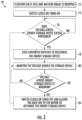
- FIG. 3 is a flowchart diagram 70 summarizing an example method of controlling movement of the elevator car using elevator machine braking as described above.
- the elevator car 22 is idle and the machine brake is applied or dropped.
- the switch 58 closes or turns on at 74.
- the controller 54 determines whether the voltage across the capacitor 52 exceeds a preselected threshold at 76. When that voltage exceeds the threshold, at 78, the controller 54 turns on the converter IGBTs 46 to discharge the capacitor 52.
- the controller 54 monitors the voltage across the capacitor 52 at 80 and determines whether that voltage reaches a preselected base magnitude at 82.
- the brake control turns off the converter IGBTs 46 and allows the back emf of the motor 50 to recharge the capacitor 52 at 84 and continues to monitor the voltage across the capacitor at 76.
- the method summarized in Figure 3 repeatedly allows the back emf of the motor 50 to charge the capacitor 52 and then discharges the capacitor 52 to keep the back emf of the motor 50 within a desired range to maintain a speed of movement of the elevator car below a desired threshold. Controlling the back emf of the motor 50 in this way provides elevator machine braking even if the machine brake is unable to prevent the traction sheave 32 from rotating.
Landscapes
- Engineering & Computer Science (AREA)
- Automation & Control Theory (AREA)
- Mechanical Engineering (AREA)
- Power Engineering (AREA)
- Civil Engineering (AREA)
- Structural Engineering (AREA)
- Computer Networks & Wireless Communication (AREA)
- Elevator Control (AREA)
Abstract
Description
- Elevator systems are in widespread use for carrying passengers between various levels in buildings, for example. Some elevator systems are traction-based in which roping that suspends the elevator car and a counterweight facilitates movement of the elevator car when needed. The roping moves in response to movement of a traction sheave, which is driven by a machine motor or prevented from rotating by a machine brake. In most situations, the machine brake is applied or dropped to stop the elevator car. Alternative or additional ways of braking movement of the elevator car at the machine are needed to comply with some elevator codes, for example.
- An illustrative example embodiment of an elevator machine assembly includes a motor and an elevator drive configured to control power supply to the motor. The elevator drive includes at least a plurality of converter switches and an energy storage device that is situated to be charged in response to the motor generating a back emf as the motor rotates in response to a torque applied to the motor when the elevator drive is not providing power to the motor. A short-circuiting module that is selectively coupled with the energy storage device through the converter switches selectively discharges the energy storage device to limit the back emf of the motor and a corresponding speed at which the motor rotates.
- Particular embodiments may include any of the following optional features, alone or in combination with other features, unless specified otherwise.
- In addition to one or more of the features described above, or as an alternative, the short-circuiting module comprises a plurality of resistors and a switch that selectively couples the resistors and the converter switches.
- In addition to one or more of the features described above, or as an alternative, the switch of the short-circuiting module couples the resistors to the converter switches in response to the elevator drive disconnecting the motor from power.
- In addition to one or more of the features described above, or as an alternative, the switch of the short-circuiting module comprises a relay switch that closes in response to the elevator drive disconnecting the motor from power.
- In addition to one or more of the features described above, or as an alternative, the elevator drive comprises a brake control that determines a voltage of the energy storage device and controls the converter switches to selectively couple the short-circuiting module and the energy storage device to maintain the voltage of the energy storage device within a preselected range.
- In addition to one or more of the features described above, or as an alternative, the converter switches each comprise an IGBT or a MOSFET and the brake control turns on the IGBTs in response to the voltage exceeding a preselected threshold.
- In addition to one or more of the features described above, or as an alternative, the brake control turns the IGBTs or MOSFETs on and off repeatedly to allow the voltage of the energy storage device to repeatedly increase and decrease within the preselected range.
- In addition to one or more of the features described above, or as an alternative, the energy storage device comprises a capacitor.
- In addition to one or more of the features described above, or as an alternative, the short-circuiting module comprises a plurality of resistors and a switch that selectively couples the resistors to the converter switches, the converter switches each comprise an IGBT or a MOSFET, and the energy storage device comprises a capacitor.
- An illustrative example embodiment includes a method of using an elevator machine to control movement of an associated elevator car. The elevator machine includes a motor configured to selectively move the elevator car and an elevator drive configured to control power supply to the motor, the elevator drive having an energy storage device and converter switches. The method includes determining that a voltage of the energy storage device exceeds a preselected threshold. The voltage of the energy storage device is based on a back emf of the motor rotating when the elevator drive is not supplying power to the motor, using the converter switches to couple the energy storage device and a short-circuiting module based on the voltage of the energy storage device exceeding the preselected threshold, and discharging the energy storage device using the short-circuiting module to maintain the voltage of the energy storage device and the back emf of the motor within respective preselected ranges.
- Particular embodiments may include any of the following optional features, alone or in combination with other features, unless specified otherwise.
- In addition to one or more of the features described above, or as an alternative, the method includes using the converter switches to uncouple the energy storage device from the short-circuiting module once the voltage of the energy storage device drops to a selected value.
- In addition to one or more of the features described above, or as an alternative, the method includes allowing the back emf of the motor to recharge the energy storage device and repeating each of determining that the voltage of the energy storage device exceeds the preselected threshold, using the converter switches to couple the energy storage device and the short-circuiting module, and discharging the energy storage device.
- In addition to one or more of the features described above, or as an alternative, the converter switches comprise IGBTs or MOSFETs and using the converter switches to couple the energy storage device and a short-circuiting module comprises selectively turning on the IGBTs or MOSFETs.
- In addition to one or more of the features described above, or as an alternative, the short-circuiting module comprises a plurality of resistors and a switch that selectively couples the resistors and the converter switches in response to the elevator drive disconnecting the motor from power.
- In addition to one or more of the features described above, or as an alternative, the switch of the short-circuiting module comprises a relay switch that closes in response to the elevator drive disconnecting the motor from power.
- In addition to one or more of the features described above, or as an alternative, the method includes repeatedly turning the converter switches on and off to allow the voltage of the energy storage device to repeatedly increase and decrease within the preselected range.
- In addition to one or more of the features described above, or as an alternative, the energy storage device comprises a capacitor.
- In addition to one or more of the features described above, or as an alternative, the short-circuiting module comprises a plurality of resistors and a switch that selectively couples the resistors and the converter switches, the converter switches each comprise an IGBT or a MOSFET, and the energy storage device comprises a capacitor.
- The various features and advantages of an example embodiment will become apparent to those skilled in the art from the following detailed description. The drawings that accompany the detailed description can be briefly described as follows.
-
Figure 1 schematically illustrates selected portions of an elevator system. -
Figure 2 schematically illustrates an elevator drive configured to provide machine braking according to an example embodiment. -
Figure 3 is a flowchart diagram summarizing a braking method according to an example embodiment. -
Figure 1 schematically illustrates selected portions of anelevator system 20. Anelevator car 22 is supported by a roping arrangement orsuspension assembly 24 that includes a plurality of load-bearingsuspension members 26. Theelevator car 22 is coupled to acounterweight 28 by thesuspension members 26. Amachine 30 includes atraction sheave 32 for controlling movement of the elevator car. As thesuspension members 26 move in response to rotation of thetraction sheave 32, theelevator car 22 andcounterweight 28 move vertically. A machine brake (not illustrated) selectively applied a braking force to prevent thetraction sheave 32 from rotating and, thereby, prevents theelevator car 22 from moving. -
Figure 2 schematically illustrates selected portions of anexample elevator drive 40 that provides machine braking that can be used even when the machine brake is unable to apply a sufficient braking force because the machine brake is malfunctioning or the load on the elevator car is too large for the machine brake to resist rotation of thetraction sheave 32. - The
example elevator drive 40 receives power from a power source, such as a utility grid, through afilter 42 whenswitch contactors 44 are turned on or conducting. Thedrive 40 includesknown converter switches 46 andinverter switches 48 that are controlled to provide power to themotor 50 of theelevator machine 30 when needed for moving theelevator car 22. In the illustrated example embodiment, theconverter switches 46 are IGBTs or MOSFETs and theinverter switches 48 are IGBTs or MOSFETs. Theswitch contactors 44 turn off or disconnect the power from the grid when the elevator car stops. The machine brake drops and applies a braking force to prevent thetraction sheave 32 from rotating while the elevator car should remain stationary. - If the
traction sheave 32 were to rotate under those conditions, themotor 50 generates back emf in a known manner that charges anenergy storage device 52, which in this example embodiment comprises a capacitor. The back emf increases as themotor 50 rotates faster. The voltage across thecapacitor 52 indicates the magnitude of the back emf. Acontroller 54 controls theconverter switches 46 or turns them on to selectively discharge thecapacitor 52 through a short-circuiting module 56. Thecontroller 54 selectively controls theconverter switches 46 based on the voltage across the capacitor to keep the back emf within a preselected range. Thecontroller 54 maintains the voltage on thecapacitor 52 and, therefore, the back emf below a predetermined threshold to limit the speed at which themotor 50 may rotate. Controlling the back emf of themotor 50 in this way effectively brakes rotation of themotor 50 and limits a speed at which the roping orsuspension assembly 24 and theelevator car 22 may move. In some embodiments, themotor 50 is allowed to rotate at a maximum speed corresponding to movement of theelevator car 22 at 0.3 m/second. - In the illustrated example embodiment, the short-
circuiting module 56 includes aswitch 58 andresistors 60. The size or resistance of theresistors 60 is based on factors such as the duty load of theelevator car 22 and characteristics of themotor 50. Thecontroller 54 monitors current flow through theresistors 60 in the illustrated example embodiment to verify that the short-circuiting module 56 is working as intended. - The illustrated example embodiment includes three
resistors 60, one for each phase of themotor 50. Another embodiment includes two resistors connected across two of the phases instead of all three phases. Another embodiment includes a single resistor across the DC link capacitor with one switch. - The
switch 58 is on or closed when thecapacitor 52 should be discharged through theresistors 60. In some embodiments, theswitch 58 turns on whenever theswitch contactors 44 disconnect thedrive 40 from the utility power grid or the elevator car is idle. Theswitch 58 comprises a relay switch in some embodiments. - The
controller 54 is schematically shown in broken lines because it may be embodied in a physical component or be a function performed by theelevator drive 40. In some embodiments, thecontroller 54 comprises software or firmware added to theelevator drive 40. In other embodiments, at least one dedicated hardware component performs the function of the illustratedcontroller 54. -
Figure 3 is a flowchart diagram 70 summarizing an example method of controlling movement of the elevator car using elevator machine braking as described above. At 72, theelevator car 22 is idle and the machine brake is applied or dropped. Theswitch 58 closes or turns on at 74. Thecontroller 54 determines whether the voltage across thecapacitor 52 exceeds a preselected threshold at 76. When that voltage exceeds the threshold, at 78, thecontroller 54 turns on theconverter IGBTs 46 to discharge thecapacitor 52. Thecontroller 54 monitors the voltage across thecapacitor 52 at 80 and determines whether that voltage reaches a preselected base magnitude at 82. The brake control turns off theconverter IGBTs 46 and allows the back emf of themotor 50 to recharge thecapacitor 52 at 84 and continues to monitor the voltage across the capacitor at 76. - The method summarized in
Figure 3 repeatedly allows the back emf of themotor 50 to charge thecapacitor 52 and then discharges thecapacitor 52 to keep the back emf of themotor 50 within a desired range to maintain a speed of movement of the elevator car below a desired threshold. Controlling the back emf of themotor 50 in this way provides elevator machine braking even if the machine brake is unable to prevent thetraction sheave 32 from rotating. - Some features or functions mentioned above as being included in an embodiment may be combined with at least one feature or function described as part of another embodiment. The features and functions described above may be combined in other ways to realize other embodiments.
- The preceding description is exemplary rather than limiting in nature. Variations and modifications to the disclosed examples may become apparent to those skilled in the art that do not necessarily depart from the essence of this invention. The scope of legal protection given to this invention can only be determined by studying the following claims.
Claims (15)
- An elevator machine assembly, comprising:a motor;an elevator drive configured to control power supply to the motor, the elevator drive including at least a plurality of converter switches and an energy storage device, the energy storage device being situated to be charged in response to the motor generating a back emf as the motor rotates in response to a torque applied to the motor when the elevator drive is not providing power to the motor; anda short-circuiting module that is selectively coupled with the energy storage device through the converter switches to selectively discharge the energy storage device to limit the back emf of the motor and a corresponding speed at which the motor rotates.
- The elevator machine assembly of claim 1, wherein the short-circuiting module comprises a plurality of resistors and a switch that selectively couples the resistors and the converter switches.
- The elevator machine assembly of claim 2, wherein the switch of the short-circuiting module couples the resistors to the converter switches in response to the elevator drive disconnecting the motor from power.
- The elevator machine assembly of claim 3, wherein the switch of the short-circuiting module comprises a relay switch that closes in response to the elevator drive disconnecting the motor from power.
- The elevator machine assembly of any one of claims 1 to 4, wherein the elevator drive comprises a brake control that determines a voltage of the energy storage device and controls the converter switches to selectively couple the short-circuiting module and the energy storage device to maintain the voltage of the energy storage device within a preselected range.
- The elevator machine assembly of claim 5, wherein the converter switches each comprise an IGBT and the brake control turns on the IGBTs in response to the voltage exceeding a preselected threshold.
- The elevator machine assembly of claim 6, wherein the brake control turns the IGBTs on and off repeatedly to allow the voltage of the energy storage device to repeatedly increase and decrease within the preselected range.
- The elevator machine assembly of any one of claims 5 to 7, wherein the energy storage device comprises a capacitor.
- The elevator machine assembly of any one of claims 1 to 8, whereinthe short-circuiting module comprises a plurality of resistors and a switch that selectively couples the resistors to the converter switches;the converter switches each comprise an IGBT; andthe energy storage device comprises a capacitor.
- A method of using an elevator machine to control movement of an associated elevator car, the elevator machine including a motor configured to selectively move the elevator car and an elevator drive configured to control power supply to the motor, the elevator drive having an energy storage device and converter switches, the method comprising:determining that a voltage of the energy storage device exceeds a preselected threshold, wherein the voltage of the energy storage device is based on a back emf of the motor rotating when the elevator drive is not supplying power to the motor;using the converter switches to couple the energy storage device and a short-circuiting module based on the voltage of the energy storage device exceeding the preselected threshold; anddischarging the energy storage device using the short-circuiting module to maintain the voltage of the energy storage device and the back emf of the motor within respective preselected ranges.
- The method of claim 10, comprising using the converter switches to uncouple the energy storage device from the short-circuiting module once the voltage of the energy storage device drops to a selected value.
- The method of claim 11, comprising allowing the back emf of the motor to recharge the energy storage device and repeating each of:determining that the voltage of the energy storage device exceeds the preselected threshold,using the converter switches to couple the energy storage device and the short-circuiting module, anddischarging the energy storage device.
- The method of any one of claims 10 to 12, whereinthe converter switches comprise IGBTs, andusing the converter switches to couple the energy storage device and a short-circuiting module comprises selectively turning on the IGBTs; and/orwherein the short-circuiting module comprises a plurality of resistors and a switch that selectively couples the resistors and the converter switches in response to the elevator drive disconnecting the motor from power;wherein particularly the switch of the short-circuiting module comprises a relay switch that closes in response to the elevator drive disconnecting the motor from power.
- The method of any one of claims 10 to 13, comprising repeatedly turning the converter switches on and off to allow the voltage of the energy storage device to repeatedly increase and decrease within the preselected range.
- The method of any one of claims 10 to 14, wherein the energy storage device comprises a capacitor; and/orwherein the short-circuiting module comprises a plurality of resistors and a switch that selectively couples the resistors and the converter switches;the converter switches each comprise an IGBT; andthe energy storage device comprises a capacitor.
Applications Claiming Priority (1)
| Application Number | Priority Date | Filing Date | Title |
|---|---|---|---|
| US18/166,511 US20240275313A1 (en) | 2023-02-09 | 2023-02-09 | Elevator machine braking |
Publications (2)
| Publication Number | Publication Date |
|---|---|
| EP4414304A1 true EP4414304A1 (en) | 2024-08-14 |
| EP4414304B1 EP4414304B1 (en) | 2026-04-01 |
Family
ID=89843535
Family Applications (1)
| Application Number | Title | Priority Date | Filing Date |
|---|---|---|---|
| EP24155571.3A Active EP4414304B1 (en) | 2023-02-09 | 2024-02-02 | An elevator machine assembly and a method of usign an elevator machine |
Country Status (3)
| Country | Link |
|---|---|
| US (1) | US20240275313A1 (en) |
| EP (1) | EP4414304B1 (en) |
| CN (1) | CN118458557A (en) |
Citations (4)
| Publication number | Priority date | Publication date | Assignee | Title |
|---|---|---|---|---|
| US5285029A (en) * | 1991-06-12 | 1994-02-08 | Mitsubishi Denki Kabushiki Kaisha | Device for driving elevator at service interruption |
| JP2001008459A (en) * | 1999-06-18 | 2001-01-12 | Hitachi Ltd | Elevator control device |
| WO2007145628A1 (en) * | 2006-06-15 | 2007-12-21 | Otis Elevator Company | Electrical energy storage system for driving a load |
| US8629637B2 (en) * | 2008-11-21 | 2014-01-14 | Otis Elevator Company | Operation of a three-phase regenerative drive from mixed DC and single phase AC power sources |
Family Cites Families (1)
| Publication number | Priority date | Publication date | Assignee | Title |
|---|---|---|---|---|
| EP3464146A1 (en) * | 2016-05-31 | 2019-04-10 | Inventio AG | Elevator drive control during power disruption |
-
2023
- 2023-02-09 US US18/166,511 patent/US20240275313A1/en active Pending
- 2023-11-23 CN CN202311567849.2A patent/CN118458557A/en active Pending
-
2024
- 2024-02-02 EP EP24155571.3A patent/EP4414304B1/en active Active
Patent Citations (4)
| Publication number | Priority date | Publication date | Assignee | Title |
|---|---|---|---|---|
| US5285029A (en) * | 1991-06-12 | 1994-02-08 | Mitsubishi Denki Kabushiki Kaisha | Device for driving elevator at service interruption |
| JP2001008459A (en) * | 1999-06-18 | 2001-01-12 | Hitachi Ltd | Elevator control device |
| WO2007145628A1 (en) * | 2006-06-15 | 2007-12-21 | Otis Elevator Company | Electrical energy storage system for driving a load |
| US8629637B2 (en) * | 2008-11-21 | 2014-01-14 | Otis Elevator Company | Operation of a three-phase regenerative drive from mixed DC and single phase AC power sources |
Also Published As
| Publication number | Publication date |
|---|---|
| CN118458557A (en) | 2024-08-09 |
| US20240275313A1 (en) | 2024-08-15 |
| EP4414304B1 (en) | 2026-04-01 |
Similar Documents
| Publication | Publication Date | Title |
|---|---|---|
| KR101242527B1 (en) | Method for operating an elevator in an emergency mode | |
| EP1931587B1 (en) | Elevator control system for regenerative power | |
| EP3287404B1 (en) | Elevator system comprising braking apparatus and electric drive | |
| WO2007013141A1 (en) | Control device for elevator | |
| MXPA04002618A (en) | Reversible dc motor drive including a dc/dc converter and four quadrant dc/dc controller. | |
| CN101360675B (en) | Control apparatus for elevator | |
| CN109219572B (en) | Elevator drive control during power interruption | |
| EP2651811B1 (en) | Regenerative power control for passenger conveyors | |
| US20240275313A1 (en) | Elevator machine braking | |
| JP2019038697A (en) | Automatic rescue and charging system for elevator drives | |
| JP4663849B2 (en) | Elevator control device | |
| WO2005108271A1 (en) | Control device for hybrid drive-type elevator | |
| JP2010168139A (en) | Elevator control device | |
| CN106241540B (en) | Drive assisted emergency stop | |
| JP4463912B2 (en) | AC elevator power supply | |
| JPS6146391B2 (en) | ||
| JPS6253435B2 (en) | ||
| EP4414305B1 (en) | LIFT DRIVE AND METHOD FOR USING A LIFT MACHINE FOR MOTION CONTROL | |
| JP2001139243A5 (en) | ||
| WO2024105763A1 (en) | Elevator system and elevator control method | |
| JP2006082944A (en) | Elevator drive device and drive method thereof | |
| CN120664420A (en) | Elevator control device | |
| KR20070117389A (en) | Inverter for Lifting System | |
| CN117645226A (en) | Multi-drive system for regenerative energy management in elevator installations | |
| HK1161581B (en) | Method for operating an elevator in an emergency mode |
Legal Events
| Date | Code | Title | Description |
|---|---|---|---|
| PUAI | Public reference made under article 153(3) epc to a published international application that has entered the european phase |
Free format text: ORIGINAL CODE: 0009012 |
|
| STAA | Information on the status of an ep patent application or granted ep patent |
Free format text: STATUS: THE APPLICATION HAS BEEN PUBLISHED |
|
| AK | Designated contracting states |
Kind code of ref document: A1 Designated state(s): AL AT BE BG CH CY CZ DE DK EE ES FI FR GB GR HR HU IE IS IT LI LT LU LV MC ME MK MT NL NO PL PT RO RS SE SI SK SM TR |
|
| STAA | Information on the status of an ep patent application or granted ep patent |
Free format text: STATUS: REQUEST FOR EXAMINATION WAS MADE |
|
| 17P | Request for examination filed |
Effective date: 20250212 |
|
| GRAP | Despatch of communication of intention to grant a patent |
Free format text: ORIGINAL CODE: EPIDOSNIGR1 |
|
| STAA | Information on the status of an ep patent application or granted ep patent |
Free format text: STATUS: GRANT OF PATENT IS INTENDED |
|
| INTG | Intention to grant announced |
Effective date: 20251020 |
|
| GRAS | Grant fee paid |
Free format text: ORIGINAL CODE: EPIDOSNIGR3 |
|
| GRAA | (expected) grant |
Free format text: ORIGINAL CODE: 0009210 |
|
| STAA | Information on the status of an ep patent application or granted ep patent |
Free format text: STATUS: THE PATENT HAS BEEN GRANTED |
|
| AK | Designated contracting states |
Kind code of ref document: B1 Designated state(s): AL AT BE BG CH CY CZ DE DK EE ES FI FR GB GR HR HU IE IS IT LI LT LU LV MC ME MK MT NL NO PL PT RO RS SE SI SK SM TR |
|
| REG | Reference to a national code |
Ref country code: CH Ref legal event code: F10 Free format text: ST27 STATUS EVENT CODE: U-0-0-F10-F00 (AS PROVIDED BY THE NATIONAL OFFICE) Effective date: 20260401 Ref country code: GB Ref legal event code: FG4D |
|
| REG | Reference to a national code |
Ref country code: IE Ref legal event code: FG4D |
|
| REG | Reference to a national code |
Ref country code: DE Ref legal event code: R096 Ref document number: 602024003495 Country of ref document: DE |