EP4414224A1 - Cleaner nozzle - Google Patents
Cleaner nozzle Download PDFInfo
- Publication number
- EP4414224A1 EP4414224A1 EP22878630.7A EP22878630A EP4414224A1 EP 4414224 A1 EP4414224 A1 EP 4414224A1 EP 22878630 A EP22878630 A EP 22878630A EP 4414224 A1 EP4414224 A1 EP 4414224A1
- Authority
- EP
- European Patent Office
- Prior art keywords
- piston
- cylinder
- cleaner nozzle
- axial direction
- coil spring
- Prior art date
- Legal status (The legal status is an assumption and is not a legal conclusion. Google has not performed a legal analysis and makes no representation as to the accuracy of the status listed.)
- Withdrawn
Links
Images





Classifications
-
- B—PERFORMING OPERATIONS; TRANSPORTING
- B08—CLEANING
- B08B—CLEANING IN GENERAL; PREVENTION OF FOULING IN GENERAL
- B08B3/00—Cleaning by methods involving the use or presence of liquid or steam
- B08B3/02—Cleaning by the force of jets or sprays
-
- B—PERFORMING OPERATIONS; TRANSPORTING
- B05—SPRAYING OR ATOMISING IN GENERAL; APPLYING FLUENT MATERIALS TO SURFACES, IN GENERAL
- B05B—SPRAYING APPARATUS; ATOMISING APPARATUS; NOZZLES
- B05B1/00—Nozzles, spray heads or other outlets, with or without auxiliary devices such as valves, heating means
- B05B1/30—Nozzles, spray heads or other outlets, with or without auxiliary devices such as valves, heating means designed to control volume of flow, e.g. with adjustable passages
- B05B1/32—Nozzles, spray heads or other outlets, with or without auxiliary devices such as valves, heating means designed to control volume of flow, e.g. with adjustable passages in which a valve member forms part of the outlet opening
- B05B1/326—Gate valves; Sliding valves; Cocks
-
- B—PERFORMING OPERATIONS; TRANSPORTING
- B05—SPRAYING OR ATOMISING IN GENERAL; APPLYING FLUENT MATERIALS TO SURFACES, IN GENERAL
- B05B—SPRAYING APPARATUS; ATOMISING APPARATUS; NOZZLES
- B05B15/00—Details of spraying plant or spraying apparatus not otherwise provided for; Accessories
- B05B15/70—Arrangements for moving spray heads automatically to or from the working position
- B05B15/72—Arrangements for moving spray heads automatically to or from the working position using hydraulic or pneumatic means
- B05B15/74—Arrangements for moving spray heads automatically to or from the working position using hydraulic or pneumatic means driven by the discharged fluid
-
- B—PERFORMING OPERATIONS; TRANSPORTING
- B60—VEHICLES IN GENERAL
- B60S—SERVICING, CLEANING, REPAIRING, SUPPORTING, LIFTING, OR MANOEUVRING OF VEHICLES, NOT OTHERWISE PROVIDED FOR
- B60S1/00—Cleaning of vehicles
- B60S1/02—Cleaning windscreens, windows or optical devices
- B60S1/46—Cleaning windscreens, windows or optical devices using liquid; Windscreen washers
- B60S1/48—Liquid supply therefor
- B60S1/52—Arrangement of nozzles; Liquid spreading means
- B60S1/522—Arrangement of nozzles; Liquid spreading means moving liquid spreading means, e.g. arranged in wiper arms
- B60S1/528—Arrangement of nozzles; Liquid spreading means moving liquid spreading means, e.g. arranged in wiper arms the spreading means being moved between a rest position and a working position
-
- B—PERFORMING OPERATIONS; TRANSPORTING
- B60—VEHICLES IN GENERAL
- B60S—SERVICING, CLEANING, REPAIRING, SUPPORTING, LIFTING, OR MANOEUVRING OF VEHICLES, NOT OTHERWISE PROVIDED FOR
- B60S1/00—Cleaning of vehicles
- B60S1/02—Cleaning windscreens, windows or optical devices
- B60S1/56—Cleaning windscreens, windows or optical devices specially adapted for cleaning other parts or devices than front windows or windscreens
Definitions
- the present disclosure relates to a cleaner nozzle.
- Patent Literature 1 A cleaner nozzle as described in Patent Literature 1 is known.
- Patent Literature 1 JP2018-034646A
- a piston is provided with an ejection port available to eject a cleaning liquid for cleaning a sensor such as a camera.
- the ejection port is required to face the sensor.
- the piston may be displaced relative to a cylinder about an axis of the cylinder, and the ejection port may deviate from the sensor.
- the cleaner nozzle described in Patent Literature 1 further includes a coil spring inside the cylinder to return the piston to an original position.
- the piston can be further displaced in an axial direction of the cylinder.
- a positional relationship between the cleaner nozzle and an object to be cleaned may differ depending on a vehicle type, it is required to adjust a displacement amount (a stroke amount) of the piston in the axial direction to reliably apply the cleaning liquid to the object to be cleaned. For this reason, the stroke amount of the piston obtained for each vehicle type differs. However, it takes time and effort to design cleaner nozzles of different specifications each time according to required stroke amounts.
- a first object of the present disclosure is to provide a cleaner nozzle in which an ejection port is less likely to deviate from an object to be cleaned.
- a second object of the present disclosure is to provide a cleaner nozzle in which a coil spring is prevented from deviating in a radial direction of a cylinder.
- a third object of the present disclosure is to provide a cleaner nozzle that can be easily mounted on various types of vehicles.
- a first aspect of the present disclosure provides a cleaner nozzle including:
- a second aspect of the present disclosure provides a cleaner nozzle including:
- a third aspect of the present disclosure provides a cleaner nozzle including:
- a fourth aspect of the present disclosure provides a cleaner nozzle including:
- a cleaner nozzle in which an ejection port is less likely to deviate from an object to be cleaned.
- a cleaner nozzle in which a coil spring is prevented from deviating in a radial direction of a cylinder. It is also possible to provide a cleaner nozzle that can be easily mounted on various types of vehicles.
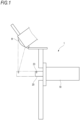
- FIG. 1 is a cross-sectional view showing a state in which the cleaner nozzle 1 according to the first embodiment is attached to a vehicle.
- the cleaner nozzle 1 is attached to the vehicle and cleans a sensor W such as a camera or a LiDAR mounted on the vehicle.
- the cleaner nozzle 1 includes a cylinder 10 and a piston 20.
- the piston 20 is provided with, at a top portion, an ejection port 23 available to eject a cleaning liquid.
- the piston 20 can be displaced in a direction of an axis Ax (see FIGS. 2 and 3 ) of the cylinder 10 relative to the cylinder 10.
- an ejection port 23 side (an upper side in FIG. 3 ) in the axial Ax direction may be referred to as a front side
- a side (a lower side in FIG. 3 ) opposite to the ejection port 23 in the axial Ax direction may be referred to as a rear side.
- the cleaning liquid is ejected from the ejection port 23.
- the piston 20 is displaced in the axial Ax direction of the cylinder 10, and the ejection port 23 moves to a position closer to the sensor W than when the cleaner nozzle 1 does not clean the sensor W.
- the sensor W can be cleaned when the cleaning liquid is ejected from the ejection port 23 in this state. That is, the cleaner nozzle 1 can be configured such that the ejection port 23 protrudes from a design surface of the vehicle only during operation, and does not protrude from the design surface of the vehicle during non-operation. Accordingly, the design of the vehicle is less likely to be impaired even when the cleaner nozzle 1 is mounted.
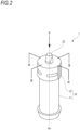
- FIG. 2 is a perspective view of the cleaner nozzle 1 according to the first embodiment.
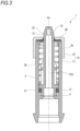
- FIG. 3 is a cross-sectional view taken along a line III-III in FIG. 2 .
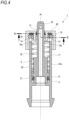
- FIG. 4 is a cross-sectional view taken along a line IV-IV in FIG. 2 .
- the cylinder 10 includes a cylindrical portion 11 and a cap 12.
- the cap 12 closes at least a part of an opening of the cylindrical portion 11.
- the cap 12 is an example of a cover portion.
- the cap 12 has a hole 13 through which a shaft portion 22 to be described later can be inserted.
- the cap 12 is provided on one end portion of the cylindrical portion 11, and covers an opening of the one end portion of the cylindrical portion 11 except for the hole 13.
- the cover portion (the cap 12) is separable from the cylindrical portion 11.
- the cover portion in the present disclosure is not limited to the example according to the present embodiment.
- the cylindrical portion 11 and the cover portion may be integrally formed.
- the cover portion (the cap 12) is provided on the one end portion of the cylindrical portion 11.
- the cover portion may be provided inside the cylindrical portion 11.
- the piston 20 includes a first seal portion 21.
- the first seal portion 21 is in water-tight contact with an inner wall of the cylinder 10.
- the cylinder 10 is divided into a spring accommodating chamber S and a hydraulic pressure chamber P by the first seal portion 21.
- the spring accommodating chamber S is a space defined between the cap 12 and the first seal portion 21 in two spaces inside the cylinder 10 partitioned by the first seal portion 21.
- a coil spring 30 is provided in the spring accommodating chamber S. The coil spring 30 returns the piston 20 to an original position by biasing the piston 20 that is displaced in the axial Ax direction and approaches the cap 12 in a direction away from the cap 12.
- the spring accommodating chamber S is provided with an air inlet and outlet 14.
- a volume of the spring accommodating chamber S decreases, and air inside the spring accommodating chamber S flows out from the air inlet and outlet 14.
- the volume of the spring accommodating chamber S increases, and air flows into the spring accommodating chamber S through the air inlet and outlet 14. Accordingly, a change in static pressure of the spring accommodating chamber S can be prevented, and the piston 20 can be displaced more smoothly by the coil spring 30.
- the hydraulic pressure chamber P is a space on a side opposite to the cap 12 relative to the first seal portion 21 in the two spaces inside the cylinder 10 partitioned by the first seal portion 21.
- the cleaning liquid is supplied to the hydraulic pressure chamber P from a supply source (not shown).
- the piston 20 includes the shaft portion 22.
- the shaft portion 22 is inserted into the coil spring 30.
- the shaft portion 22 has the ejection port 23 that ejects the cleaning liquid.
- the ejection port 23 is provided in an end portion on a cap 12 side of the shaft portion 22.
- the ejection port 23 may be provided anywhere as long as the ejection port 23 is exposed when the piston 20 is displaced in the axial Ax direction.
- the shaft portion 22 has an internal flow path 22a therein.
- the internal flow path 22a communicates with the hydraulic pressure chamber P.
- the internal flow path 22a also communicates with the ejection port 23.
- FIG. 5 is a view seen from a V direction (the axial Ax direction) in FIG. 2 .
- the shaft portion 22 and the hole 13 have corresponding shapes when viewed in the axial Ax direction.
- the shaft portion 22 has a so-called track-shaped shape including two parallel linear portions and two arc-shaped portions connecting the linear portions when viewed from the axial Ax direction.
- the arc-shaped portions are referred to as piston side curved surface portions 26, and the linear portions are referred to as piston side flat surface portions 27.
- An inner peripheral edge of the hole 13 has a shape corresponding to an outer peripheral edge of the shaft portion 22.
- the hole 13 is defined by cylinder side curved surface portions 16 having shapes corresponding to the piston side curved surface portions 26 and cylinder side flat surface portions 17 having shapes corresponding to the piston side flat surface portions 27.
- the piston side flat surface portions 27 and the cylinder side flat surface portions 17 correspond to prevention portions that prevent relative rotation between the cylinder 10 and the piston 20.
- a plurality of piston side flat surface portions 27 and cylinder side flat surface portions 17 are preferably provided. In the present embodiment, each two of the piston side flat surface portions 27 and each two of the cylinder side flat surface portions 17 have the axis Ax sandwiched in between.
- the ejection port 23 needs to be directed at a direction of the object to be cleaned.
- a detection surface of the sensor W is usually a relatively small member, and the cleaner nozzle 1 is required to eject the cleaning liquid to an accurate position.
- the piston 20 When the piston 20 is repeatedly displaced in the axial Ax direction relative to the cylinder 10, the piston 20 may unintentionally rotate about the axis Ax relative to the cylinder 10.
- the displacement of the piston 20 about the axis Ax relative to the cylinder 10 is prevented by the piston side flat surface portions 27 and the cylinder side flat surface portions 17 that constitute the prevention portions. For this reason, a posture in which the ejection port 23 faces the object to be cleaned is easy to maintain. Accordingly, it is possible to provide the cleaner nozzle 1 in which the ejection port 23 is less likely to deviate from the object to be cleaned.
- the prevention portions are the piston side flat surface portions 27 of the piston 20 and the cylinder side flat surface portions 17 of the cylinder 10 that face the piston side flat surface portions 27. According to the above configuration, the prevention portions can be provided in a simple configuration in which the piston side flat surface portions 27 are provided in the piston 20 as flat surface portions and the cylinder side flat surface portions 17 are provided in the cylinder 10 as flat surface portions.
- the relative displacement between the piston 20 and the cylinder 10 about the axis Ax can be kept within a predetermined range with higher reproducibility.
- a part of the cylinder side flat surface portion 17 constitutes the hole 13 provided in the cap 12 (the cover portion).
- the piston side flat surface portion 27 is a portion in contact with the hole 13.
- At least two cylinder side flat surface portions 17 and at least two piston side flat surface portions 27 are provided. For this reason, the relative displacement between the piston 20 and the cylinder 10 about the axis Ax is easier to prevent than when only one cylinder side flat surface portion 17 and only one piston side flat surface portion 27 are provided.
- At least two cylinder side flat surface portions 17 have the axis Ax sandwiched in between when viewed from the axial Ax direction. Since two or more cylinder side flat surface portions 17 are provided at separated positions, it is easy to more efficiently prevent the relative displacement between the cylinder 10 and the piston 20 about the axis Ax.
- FIG. 6 is a cross-sectional view taken along a line VI-VI in FIG. 4 .
- the cap 12 includes a guide portion 18 that comes into contact with and holds the coil spring 30. As shown in FIG. 4 , the guide portion 18 extends to a side opposite to the ejection port 23. That is, the guide portion 18 extends into the spring accommodating chamber S.
- each of the guide portions 18 is in contact with an inner peripheral surface 30a of the coil spring 30.
- the guide portion 18 has a flat surface 18a that is flat when viewed from the axial Ax direction.
- the flat surface 18a faces the piston side flat surface portion 27.
- the guide portion 18 is provided on the cap 12 (the cover portion) such that the flat surface 18a of the guide portion 18 faces the piston side flat surface portion 27.
- the separate cap 12 is easily attached to the cylindrical portion 11 by inserting the piston 20 into the cylindrical portion 11 and fitting the cap 12 into the cylindrical portion 11 such that the guide portion 18 of the cap 12 faces the piston side flat surface portion 27. Accordingly, the cleaner nozzle 1 can be easily assembled.
- the guide portion 18 supports the inner peripheral surface 30a of the coil spring 30. For this reason, compared to a case in which the guide portion 18 supports an outer peripheral surface of the coil spring 30, the cleaner nozzle 1 is less likely to have a large size.
- At least two guide portions 18 are provided and have the axis Ax sandwiched in between when viewed from the axial Ax direction. Since a plurality of guide portions 18 are separated from each other, the inner peripheral surface 30a of the coil spring 30 can be more effectively supported. Accordingly, it is possible to further prevent the coil spring 30 from deviating relative to the cylinder 10.
- a cleaning fluid is ejected from the ejection port 23 through the internal flow path 22a when the static pressure of the cleaning fluid in the hydraulic pressure chamber P is increased.
- the piston 20 is displaced forward so that the ejection port 23 approaches the sensor W. Since the coil spring 30 is provided in the spring accommodating chamber S, the displaced piston 20 can be returned to the original position.
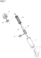
- FIG. 7 is an exploded perspective view of the cleaner nozzle 1 according to the present embodiment.
- the cleaner nozzle 1 according to the present embodiment includes a second seal portion 40.
- the second seal portion 40 is provided between the coil spring 30 and the cap 12.
- the second seal portion 40 is preferably made of rubber.
- the second seal portion 40 has a shaft portion through hole 41 through which the shaft portion 22 that is a part of the piston 20 passes, and a guide portion through hole 42 through which the guide portion 18 passes.
- the second seal portion 40 surrounds the shaft portion 22 and the guide portion 18.
- the second seal portion 40 covers a periphery of the piston 20, and thus it is possible to reduce inflow of dust or the like from the periphery of the piston 20.
- the second seal portion 40 has the guide portion through hole 42 through which the guide portion 18 passes. If the second seal portion 40 has elasticity and the guide portion through hole 42 has a diameter smaller than that of the guide portion 18, the second seal portion 40 is less likely to come off due to a frictional force with the guide portion 18 even in a state in which the second seal portion 40 is attached to the cover portion and the guide portion 18 faces downward.
- FIG. 8 is a view of the cleaner nozzle 1A according to the first modification as viewed from the axial Ax direction.
- a shaft portion 22A (an example of a piston side prevention portion) of the cleaner nozzle 1A according to the first modification has an oval shape when viewed from the axial Ax direction. That is, the shaft portion 22A according to the first modification does not include the piston side curved surface portion 26 or the piston side flat surface portion 27.
- a hole 13A (an example of a cylinder side prevention portion) through which the shaft portion 22A is inserted also does not include the cylinder side curved surface portion 16 or the cylinder side flat surface portion 17, but has an oval shape when viewed from the axial Ax direction.
- an outer peripheral edge of the piston side prevention portion when viewed in the axial Ax direction of the cylinder 10A, includes, about the axis Ax, a piston side large diameter portion 26A having a large radial dimension and a piston side small diameter portion 27A having a small radial dimension.
- the piston side large diameter portion 26A and the piston side small diameter portion 27A of the piston side prevention portion are alternately provided along a circumferential direction.
- an inner peripheral edge of the cylinder side prevention portion When viewed from the axial Ax direction of the cylinder 10A, an inner peripheral edge of the cylinder side prevention portion includes, about the axis Ax, a cylinder side large diameter portion 16A having a large radial dimension and a cylinder side small diameter portion 17A having a small radial dimension.
- the cylinder side large diameter portions 16A and the cylinder side small diameter portions 17A of the cylinder side prevention portion are alternately provided along the circumferential direction.
- the piston side small diameter portion 27A faces the cylinder side small diameter portion 17A
- the piston side large diameter portion 26A faces the cylinder side large diameter portion 16A.
- prevention portions including the piston side prevention portion and the cylinder side prevention portion have a flat shape when viewed from the axial Ax direction of the cylinder 10A. For this reason, when a piston 20A rotates relative to the cylinder 10A, the piston side large diameter portion 26A comes into contact with the adjacent cylinder side large diameter portion 16A due to the flat shape of the prevention portions, and further rotation of the piston 20A is prevented. Accordingly, it is possible to provide the cleaner nozzle 1A in which an ejection port 23A is less likely to deviate from an object to be cleaned.
- FIG. 9 is a view of a cleaner nozzle 1B according to a second modification as viewed from an axial direction.
- a shaft portion 22B and a hole 13B that constitute prevention portions have a substantially polygonal shape.
- the "substantially polygonal shape” is basically a polygonal shape, and may also be rounded to an extent that relative rotation can be prevented. For example, as shown in FIG. 9 , if the relative rotation can be prevented, parts of sides of a regular triangle may be curved. Further, parts corresponding to vertices of the regular triangle may be rounded as long as the relative rotation can be prevented.
- a basic shape of the substantially polygonal shape is not limited to a regular polygonal shape.
- the cleaner nozzle 1B according to the second modification even when the prevention portions provided in a cylinder 10B and a piston 20B have a substantially polygonal shape, the relative rotation of the cylinder 10B and the piston 20B is prevented by the parts corresponding to vertices of the substantially polygonal shape coming into contact with each other. Accordingly, it is possible to provide the cleaner nozzle 1B in which an ejection port 23B is less likely to deviate from an object to be cleaned.
- a radial dimension of the prevention portions from a rotation center changes around the circumferential direction, a portion where the radial dimension of the piston 20B is large comes into contact with a portion where the radial dimension of the cylinder 10B is small during the relative rotation of the piston 20B and the cylinder 10B, and the shape of the prevention portion is not particularly limited as long as the prevention portions have a shape that prevents the relative rotation of the piston 20B and the cylinder 10B.
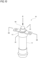
- FIG. 10 is a perspective view of the cleaner nozzle 101 according to the second embodiment.
- FIG. 11 is a cross-sectional view taken along a line XI-XI in FIG. 10 .
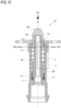
- FIG. 12 is a cross-sectional view taken along a line XII-XII in FIG. 10 .
- An ejection port 123 of the cleaner nozzle 101 according to the second embodiment is not directly provided in the piston 20 as the ejection port 23 of the cleaner nozzle 1 according to the first embodiment, but is provided by attaching a covering portion 150 including the ejection port 123 to a shaft portion 122 of a piston 120.
- the covering portion 150 is preferably in contact with a periphery of a hole 113 provided in a cap 112 that closes a part of an opening of a cylindrical portion 111. At this time, it is possible to reduce inflow of dust or the like into the covering portion 150 from a gap between the hole 113 and the shaft portion 122.
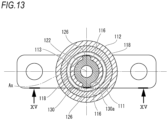
- FIG. 13 is a cross-sectional view taken along a line XIII-XIII in FIG. 12 .
- the shaft portion 122 of the cleaner nozzle 101 according to the second embodiment includes a protruding portion 126.
- the hole 113 provided in the cap 112 is provided with a recessed portion 116 (an example of a prevention portion) corresponding to the protruding portion 126.
- a plurality of protruding portions 126 are preferably provided. In the present embodiment, two protruding portions 126 are provided and have the axis Ax sandwiched in between. As shown in FIG. 11 , the protruding portion 126 extends in the axial Ax direction.
- the cleaner nozzle 101 according to the present embodiment, the displacement of the piston 120 about the axis Ax relative to the cylinder 110 is prevented by the recessed portion 116 (the prevention portion). For this reason, a posture in which the ejection port 123 faces an object to be cleaned is easy to maintain. Accordingly, it is possible to provide the cleaner nozzle 101 in which the ejection port 123 is less likely to deviate from the object to be cleaned.
- the protruding portion 126 of the cleaner nozzle 101 extends in the axial Ax direction, even when the piston 120 is displaced in the axial Ax direction relative to the cylinder 110, the protruding portion 126 and the recessed portion 116 that is the prevention portion can remain continuous contact with each other.
- the protruding portions 126 of the cleaner nozzle 101 according to the present embodiment have the axis Ax sandwiched in between when viewed from the axial Ax direction. That is, since the protruding portions 126 are separately provided, it is possible to more effectively prevent the relative displacement between the piston 120 and the cylinder 110 about the axis Ax.
- space inside the cylinder 110 according to the second embodiment is partitioned into the hydraulic pressure chamber P and the spring accommodating chamber S by a first seal portion 121.
- a coil spring 130 that moves the piston 120 away from the cap 112 that is an example of a cover portion is provided inside the spring accommodating chamber S.
- the shaft portion 122 that is a part of the piston 120 is provided inside the coil spring 130.
- the protruding portion 126 is in contact with an inner peripheral surface 130a of the coil spring 130 and supports the coil spring 130.
- the cap 112 is provided with a guide portion 118 extending rearward (opposite to the ejection port 123) in the axial Ax direction.
- the guide portion 118 preferably has an arc shape when viewed from the axial Ax direction. As shown in FIG. 13 , the guide portion 118 is inserted into a space defined by an outer wall surface of the shaft portion 122 including the protruding portion 126 and the inner peripheral surface 130a of the coil spring 130. In the present embodiment, since two protruding portions 126 are provided, there are also two spaces. The guide portion 118 is inserted into each of the two spaces.
- the guide portion 118 also come into contact with the inner peripheral surface 130a of the coil spring 130 to support the coil spring 130.
- FIG. 14 is an exploded perspective view of the cleaner nozzle 101 according to the second embodiment.
- FIG. 15 is a cross-sectional view taken along a line XV-XV in FIG. 13 .
- the coil spring 130 and the covering portion 150 are not shown for convenience of illustration.
- the piston 120 to which the first seal portion 121 is attached is inserted into the cylindrical portion 111 of the cylinder 110.
- the coil spring 130 is attached to the piston 120.
- the protruding portion 126 provided on the shaft portion 122 of the piston 120 comes into contact with the inner peripheral surface 130a of the coil.
- the cap 112 separated from the cylindrical portion 111 is attached to the cylindrical portion 111.
- the cap 112 is attached to the cylindrical portion 111 by inserting and fitting the guide portion 118 provided in the cap 112 into the space defined by the piston 120 including the protruding portion 126 and the inner peripheral surface 130a of the coil.
- the protruding portion 126 as a main body, the protruding portion 126 is accommodated in a gap between the guide portions 118.
- the gap between the guide portions 118 widens toward top ends of the guide portions 118.
- the guide portion 118 is formed in such a shape that a distance from the protruding portion 126 increases toward the top end thereof.
- the coil spring 130 of the cleaner nozzle 101 according to the present embodiment is supported by the protruding portion 126, the coil spring 130 is less likely to deviate relative to the cylinder 110. Accordingly, even when the coil spring 130 repeatedly expands and contracts, an orientation of a biasing force by the coil spring 130 is less likely to change, and thus the piston 120 displaced toward the cap 112 that is the cover portion is easily returned to an original position.
- the cleaner nozzle is not necessarily assembled in a state in which components are satisfactorily seen.
- the cap needs to be attached in a correct position and orientation in a state in which component details are invisible.
- the piston 120 is inserted into the cylindrical portion 111, and the guide portion 118 of the cap 112 is fitted into the space defined by an outer wall surface of the piston 120 including the protruding portion 126 and the coil spring 130.
- the cap 112 which is a separate cover portion, is easily attached to the cylindrical portion 111. Accordingly, the cleaner nozzle 101 can be easily assembled.
- the plurality of protruding portions 126 are accommodated in gaps of the guide portions 118.
- the protruding portions 126 and the guide portions 118 come into contact with each other. This further prevents the relative displacement between the piston 120 and the cylinder 110 about the axis Ax.
- the gaps between the arc-shaped guide portions 118 each have a shape that widens toward the top end (forward in the axial Ax direction). At this time, since the top ends of the gaps are widened, the guide portions 118 are easily inserted into the spaces defined by the outer wall surface of the piston 120 including the protruding portion 126 and the coil spring 130.
- An assembling method includes a step of attaching the cap 112, which is a cover portion, to the cylindrical portion 111 so as to insert the guide portions 118 into the spaces defined by the outer wall surface of the piston 120 including the protruding portion 126 and the coil spring 130.
- a position and an orientation of the cap 112 are guided.
- a space defined by the cylindrical portion 111 and the cap 112 cannot be visually recognized by an operator, and thus it is difficult to perform accurate assembly.
- the spaces into which the guide portions 118 are inserted are already defined as the spaces defined by the outer wall surface of the piston 120 including the protruding portion 126 and the coil spring 130, the cleaner nozzle 101 can be assembled with high accuracy.
- the piston 120 of the cleaner nozzle 101 includes a restricting portion 160.
- the restricting portion 160 protrudes in a radial direction from the shaft portion 122 of the piston 120.
- FIGS. 16A and 16B show a restriction of a stroke amount Ls by the restricting portion 160 and the guide portion 118.
- FIG. 16A is an enlarged view of a region A in FIG. 12 .
- a state shown in FIG. 16A is a state in which the restricting portion 160 and the guide portion 118 are separated from each other.
- a state shown in FIG. 16B is a state in which the piston 120 is displaced forward in the axial Ax direction relative to the cylinder 110 from the state shown in FIG. 16A , and the restricting portion 160 is in contact with the guide portion 118.
- the piston 120 cannot be further displaced in the axial Ax direction. That is, a rear end portion of the guide portion 118 in the axial Ax direction determines a forward limit position of the displacement of the piston 120 in the axial Ax direction.
- a required stroke amount of a piston may differ for each vehicle type. This is because a distance between a position where the cleaner nozzle is mounted and an object to be cleaned such as a sensor may change for each vehicle type.
- the cleaner nozzle 101 Even when the stroke amount Ls obtained for each vehicle type differs as described above, according to the cleaner nozzle 101 according to the present embodiment, it is not necessary to redesign the entire cleaner nozzle 101, and only the cap 112 including the guide portion 118 may be designed to have a length corresponding to the required stroke amount Ls. For this reason, it is possible to implement the cleaner nozzle 101 that can easily cope with various types of vehicles.
- the guide portions 118 can come into contact with the restricting portion 160 in a plurality of positions. Accordingly, it is possible to more effectively restrict the stroke amount Ls of the piston 120.
- the guide portions 118 are separated from each other with the axis Ax sandwiched in between, the guide portions 118 and the restricting portion 160 are easily stabilized in a contact state. Accordingly, when the stroke amount Ls of the piston 120 is restricted, it is possible to prevent the piston 120 from moving in an unintended direction.
- the guide portions 118 support the inner peripheral surface 130a of the coil spring 130, the movement of the coil spring 130 relative to the cap 112 and the cylinder 110 is restricted. This makes it less likely for the coil spring 130 to deviate in a radial direction relative to the cylinder 110.
- the present disclosure has been described above based on the embodiments.
- the present embodiments are examples of the present disclosure, and the present disclosure is not limited to the above-described embodiments and can be appropriately modified or improved.
- materials, shapes, dimensions, numerical values, forms, numbers, arrangement places, and the like of components in the above-described embodiments are freely selected and are not limited as long as the present disclosure can be implemented.
- the prevention portion is not necessarily provided in the cover portion. Since the cylinder side prevention portion extends from the inner wall surface of the cylinder in the axial direction of the cylinder, the piston and the cylinder may come into contact with each other to prevent the relative rotation about the axis between the piston and the cylinder.
- JP2021-166302A Japanese patent application
- JP2021-166303A Japanese patent application
- JP2021-166305A Japanese patent application
Landscapes
- Engineering & Computer Science (AREA)
- Mechanical Engineering (AREA)
- Water Supply & Treatment (AREA)
- Nozzles (AREA)
Abstract
Description
- The present disclosure relates to a cleaner nozzle.
- A cleaner nozzle as described in
Patent Literature 1 is known. - Patent Literature 1:
JP2018-034646A - As shown in the cleaner nozzle described in
Patent Literature 1, a piston is provided with an ejection port available to eject a cleaning liquid for cleaning a sensor such as a camera. To clean the sensor, the ejection port is required to face the sensor. However, the piston may be displaced relative to a cylinder about an axis of the cylinder, and the ejection port may deviate from the sensor. - The cleaner nozzle described in
Patent Literature 1 further includes a coil spring inside the cylinder to return the piston to an original position. - However, when a position of the coil spring in a radial direction deviates inside the cylinder, the coil spring cannot uniformly apply an elastic restoring force to the piston. In this case, the piston would not be returned to the original position and, when the piston is pushed out against the elastic restoring force of the coil spring to discharge the cleaning liquid, a discharge position and discharge posture thereof deviate from an original position and posture.
- In the cleaner nozzle described in
Patent Literature 1, the piston can be further displaced in an axial direction of the cylinder. - Since a positional relationship between the cleaner nozzle and an object to be cleaned may differ depending on a vehicle type, it is required to adjust a displacement amount (a stroke amount) of the piston in the axial direction to reliably apply the cleaning liquid to the object to be cleaned. For this reason, the stroke amount of the piston obtained for each vehicle type differs. However, it takes time and effort to design cleaner nozzles of different specifications each time according to required stroke amounts.
- A first object of the present disclosure is to provide a cleaner nozzle in which an ejection port is less likely to deviate from an object to be cleaned.
- A second object of the present disclosure is to provide a cleaner nozzle in which a coil spring is prevented from deviating in a radial direction of a cylinder.
- A third object of the present disclosure is to provide a cleaner nozzle that can be easily mounted on various types of vehicles.
- A first aspect of the present disclosure provides a cleaner nozzle including:
- a cylinder extending in an axial direction; and
- a piston having an ejection port and being displaceable in the axial direction in the cylinder, wherein
- the piston and the cylinder are provided with respective prevention portions that prevent relative displacement of the cylinder and the piston about an axis by coming into contact with each other.
- A second aspect of the present disclosure provides a cleaner nozzle including:
- a cylinder extending in an axial direction; and
- a piston having an ejection port and being displaceable in the axial direction in the cylinder, wherein
- the piston includes a protruding portion protruding in a radial direction of the cylinder, and
- the piston is provided with a prevention portion that prevents displacement of the piston about an axis relative to the cylinder by coming into contact with the protruding portion.
- A third aspect of the present disclosure provides a cleaner nozzle including:
- a cylinder; and
- a piston that is displaceable in an axial direction of the cylinder in the cylinder, wherein
- the cylinder includes a cover portion covering at least a part of an opening,
- a coil spring that moves the piston away from the cover portion is provided inside the cylinder, and
- a guide portion that extends toward the coil spring in the axial direction and comes into contact with the coil spring is provided in the cover portion.
- A fourth aspect of the present disclosure provides a cleaner nozzle including:
- a cylinder; and
- a piston displaceable in an axial direction of the cylinder relative to the cylinder, wherein
- the cylinder includes a cylindrical portion and a cover portion that covers at least a part of an opening of the cylindrical portion and is separate from the cylindrical portion, and
- the cover portion is provided with a guide portion that extends in the axial direction and restricts a length of the piston displaceable in the axial direction by coming into contact with the piston.
- According to the present disclosure, it is possible to provide a cleaner nozzle in which an ejection port is less likely to deviate from an object to be cleaned. According to the present disclosure, it is possible to provide a cleaner nozzle in which a coil spring is prevented from deviating in a radial direction of a cylinder. It is also possible to provide a cleaner nozzle that can be easily mounted on various types of vehicles.
-
-
FIG. 1 is a schematic cross-sectional view showing an outline of a cleaner nozzle according to a first embodiment. -
FIG. 2 is a perspective view of the cleaner nozzle according to the first embodiment. -
FIG. 3 is a cross-sectional view taken along a line III-III inFIG. 2 . -
FIG. 4 is a cross-sectional view taken along a line IV-IV inFIG. 2 . -
FIG. 5 is a view seen from a direction V inFIG. 2 . -
FIG. 6 is a cross-sectional view taken along a line VI-VI inFIG. 4 . -
FIG. 7 is an exploded perspective view of the cleaner nozzle according to the present embodiment. -
FIG. 8 shows a cleaner nozzle according to a first modification as viewed from an axial direction. -
FIG. 9 shows a cleaner nozzle according to a second modification as viewed from an axial direction. -
FIG. 10 is a perspective view of a cleaner nozzle according to a second embodiment. -
FIG. 11 is a cross-sectional view taken along a line XI-XI inFIG. 10 . -
FIG. 12 is a cross-sectional view taken along a line XII-XII inFIG. 10 . -
FIG. 13 is a cross-sectional view taken along a line XIII-XIII inFIG. 12 . -
FIG. 14 is an exploded perspective view of the cleaner nozzle according to the second embodiment. -
FIG. 15 is a cross-sectional view taken along a line XV-XV inFIG. 13 . -
FIG. 16A shows a restriction on a stroke amount by a restricting portion and a guide portion. -
FIG. 16B shows the restriction on the stroke amount by the restricting portion and the guide portion. - Hereinafter, embodiments of the present disclosure will be described with reference to the drawings. Members having the same reference numerals as those already described in the description of the embodiments will not be described for convenience of description. Further, for convenience of description, dimensions of members shown in the drawings may be different from actual dimensions of the members.
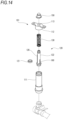
- First, a
cleaner nozzle 1 according to a first embodiment will be described.FIG. 1 is a cross-sectional view showing a state in which thecleaner nozzle 1 according to the first embodiment is attached to a vehicle. Thecleaner nozzle 1 is attached to the vehicle and cleans a sensor W such as a camera or a LiDAR mounted on the vehicle. Thecleaner nozzle 1 includes acylinder 10 and apiston 20. Thepiston 20 is provided with, at a top portion, anejection port 23 available to eject a cleaning liquid. - The
piston 20 can be displaced in a direction of an axis Ax (seeFIGS. 2 and3 ) of thecylinder 10 relative to thecylinder 10. In the following description, anejection port 23 side (an upper side inFIG. 3 ) in the axial Ax direction may be referred to as a front side, and a side (a lower side inFIG. 3 ) opposite to theejection port 23 in the axial Ax direction may be referred to as a rear side. - When the
piston 20 is displaced relative to thecylinder 10, the cleaning liquid is ejected from theejection port 23. When thecleaner nozzle 1 cleans the sensor W, thepiston 20 is displaced in the axial Ax direction of thecylinder 10, and theejection port 23 moves to a position closer to the sensor W than when thecleaner nozzle 1 does not clean the sensor W. The sensor W can be cleaned when the cleaning liquid is ejected from theejection port 23 in this state. That is, thecleaner nozzle 1 can be configured such that theejection port 23 protrudes from a design surface of the vehicle only during operation, and does not protrude from the design surface of the vehicle during non-operation. Accordingly, the design of the vehicle is less likely to be impaired even when thecleaner nozzle 1 is mounted. -
FIG. 2 is a perspective view of thecleaner nozzle 1 according to the first embodiment.FIG. 3 is a cross-sectional view taken along a line III-III inFIG. 2 .FIG. 4 is a cross-sectional view taken along a line IV-IV inFIG. 2 . As shown inFIGS. 2 to 4 , thecylinder 10 includes acylindrical portion 11 and acap 12. Thecap 12 closes at least a part of an opening of thecylindrical portion 11. Thecap 12 is an example of a cover portion. In thecleaner nozzle 1 according to the present embodiment, thecap 12 has ahole 13 through which ashaft portion 22 to be described later can be inserted. Thecap 12 is provided on one end portion of thecylindrical portion 11, and covers an opening of the one end portion of thecylindrical portion 11 except for thehole 13. - In the present embodiment, the cover portion (the cap 12) is separable from the
cylindrical portion 11. However, the cover portion in the present disclosure is not limited to the example according to the present embodiment. For example, thecylindrical portion 11 and the cover portion may be integrally formed. - In the present embodiment, the cover portion (the cap 12) is provided on the one end portion of the
cylindrical portion 11. Alternatively, the cover portion may be provided inside thecylindrical portion 11. - The
piston 20 includes afirst seal portion 21. Thefirst seal portion 21 is in water-tight contact with an inner wall of thecylinder 10. Thecylinder 10 is divided into a spring accommodating chamber S and a hydraulic pressure chamber P by thefirst seal portion 21. - The spring accommodating chamber S is a space defined between the
cap 12 and thefirst seal portion 21 in two spaces inside thecylinder 10 partitioned by thefirst seal portion 21. Acoil spring 30 is provided in the spring accommodating chamber S. Thecoil spring 30 returns thepiston 20 to an original position by biasing thepiston 20 that is displaced in the axial Ax direction and approaches thecap 12 in a direction away from thecap 12. - The spring accommodating chamber S is provided with an air inlet and
outlet 14. When thepiston 20 is displaced in the axial Ax direction and approaches thecap 12, a volume of the spring accommodating chamber S decreases, and air inside the spring accommodating chamber S flows out from the air inlet andoutlet 14. Conversely, when thepiston 20 is displaced in the direction away from thecap 12, the volume of the spring accommodating chamber S increases, and air flows into the spring accommodating chamber S through the air inlet andoutlet 14. Accordingly, a change in static pressure of the spring accommodating chamber S can be prevented, and thepiston 20 can be displaced more smoothly by thecoil spring 30. - The hydraulic pressure chamber P is a space on a side opposite to the
cap 12 relative to thefirst seal portion 21 in the two spaces inside thecylinder 10 partitioned by thefirst seal portion 21. The cleaning liquid is supplied to the hydraulic pressure chamber P from a supply source (not shown). - The
piston 20 includes theshaft portion 22. Theshaft portion 22 is inserted into thecoil spring 30. Theshaft portion 22 has theejection port 23 that ejects the cleaning liquid. In the present embodiment, theejection port 23 is provided in an end portion on acap 12 side of theshaft portion 22. Alternatively, theejection port 23 may be provided anywhere as long as theejection port 23 is exposed when thepiston 20 is displaced in the axial Ax direction. - The
shaft portion 22 has aninternal flow path 22a therein. Theinternal flow path 22a communicates with the hydraulic pressure chamber P. Theinternal flow path 22a also communicates with theejection port 23. - When the supply source feeds the cleaning liquid into the hydraulic pressure chamber P and static pressure of the cleaning liquid in the hydraulic pressure chamber P increases, since the static pressure of the cleaning liquid in the hydraulic pressure chamber P increases, the
piston 20 is displaced toward thecap 12 in the axial Ax direction against an elastic restoring force of thecoil spring 30. When the elastic restoring force of thecoil spring 30 and the static pressure are balanced, thepiston 20 is no longer displaced. When the cleaning liquid is further fed into the hydraulic pressure chamber P in this state, the cleaning liquid is discharged from theejection port 23 through theinternal flow path 22a. Accordingly, as shown inFIG. 1 , thepiston 20 protrudes from thecap 12, and the sensor W can be cleaned in a state in which theejection port 23 approaches the sensor W. - When the cleaning of the sensor W is completed, supply of the cleaning liquid from the supply source is stopped. The
piston 20 is displaced in the direction away from thecap 12 by the elastic restoring force of thecoil spring 30, and returns to a position before start of the cleaning. -
FIG. 5 is a view seen from a V direction (the axial Ax direction) inFIG. 2 . As shown inFIG. 5 , theshaft portion 22 and thehole 13 have corresponding shapes when viewed in the axial Ax direction. In thecleaner nozzle 1 according to the first embodiment, theshaft portion 22 has a so-called track-shaped shape including two parallel linear portions and two arc-shaped portions connecting the linear portions when viewed from the axial Ax direction. The arc-shaped portions are referred to as piston side curvedsurface portions 26, and the linear portions are referred to as piston sideflat surface portions 27. An inner peripheral edge of thehole 13 has a shape corresponding to an outer peripheral edge of theshaft portion 22. That is, thehole 13 is defined by cylinder side curvedsurface portions 16 having shapes corresponding to the piston side curvedsurface portions 26 and cylinder sideflat surface portions 17 having shapes corresponding to the piston sideflat surface portions 27. The piston sideflat surface portions 27 and the cylinder sideflat surface portions 17 correspond to prevention portions that prevent relative rotation between thecylinder 10 and thepiston 20. A plurality of piston sideflat surface portions 27 and cylinder sideflat surface portions 17 are preferably provided. In the present embodiment, each two of the piston sideflat surface portions 27 and each two of the cylinder sideflat surface portions 17 have the axis Ax sandwiched in between. - In order for the
cleaner nozzle 1 to effectively clean an object to be cleaned such as the sensor W, theejection port 23 needs to be directed at a direction of the object to be cleaned. In particular, a detection surface of the sensor W is usually a relatively small member, and thecleaner nozzle 1 is required to eject the cleaning liquid to an accurate position. - When the
piston 20 is repeatedly displaced in the axial Ax direction relative to thecylinder 10, thepiston 20 may unintentionally rotate about the axis Ax relative to thecylinder 10. - Thus, according to the
cleaner nozzle 1 in the present embodiment, the displacement of thepiston 20 about the axis Ax relative to thecylinder 10 is prevented by the piston sideflat surface portions 27 and the cylinder sideflat surface portions 17 that constitute the prevention portions. For this reason, a posture in which theejection port 23 faces the object to be cleaned is easy to maintain. Accordingly, it is possible to provide thecleaner nozzle 1 in which theejection port 23 is less likely to deviate from the object to be cleaned. - In the above-described embodiment, the prevention portions are the piston side
flat surface portions 27 of thepiston 20 and the cylinder sideflat surface portions 17 of thecylinder 10 that face the piston sideflat surface portions 27. According to the above configuration, the prevention portions can be provided in a simple configuration in which the piston sideflat surface portions 27 are provided in thepiston 20 as flat surface portions and the cylinder sideflat surface portions 17 are provided in thecylinder 10 as flat surface portions. - By abutting the flat surfaces against each other, the relative displacement between the
piston 20 and thecylinder 10 about the axis Ax can be kept within a predetermined range with higher reproducibility. - A part of the cylinder side
flat surface portion 17 constitutes thehole 13 provided in the cap 12 (the cover portion). The piston sideflat surface portion 27 is a portion in contact with thehole 13. When thepiston 20 is inserted through thehole 13, the cylinder sideflat surface portion 17, which is a part of the cap 12 (the cover portion) constituting thehole 13, and theshaft portion 22, which is a part of thepiston 20, come into contact with each other. Since the prevention portions are provided at a portion where thecap 12 comes into contact with thepiston 20, design of the prevention portions can be simplified. - According to the above configuration, at least two cylinder side
flat surface portions 17 and at least two piston sideflat surface portions 27 are provided. For this reason, the relative displacement between thepiston 20 and thecylinder 10 about the axis Ax is easier to prevent than when only one cylinder sideflat surface portion 17 and only one piston sideflat surface portion 27 are provided. - According to the above configuration, at least two cylinder side
flat surface portions 17 have the axis Ax sandwiched in between when viewed from the axial Ax direction. Since two or more cylinder sideflat surface portions 17 are provided at separated positions, it is easy to more efficiently prevent the relative displacement between thecylinder 10 and thepiston 20 about the axis Ax. - A
guide portion 18 of thecleaner nozzle 1 according to the first embodiment will be described with reference toFIGS. 4 and6. FIG. 6 is a cross-sectional view taken along a line VI-VI inFIG. 4 . - The
cap 12 includes aguide portion 18 that comes into contact with and holds thecoil spring 30. As shown inFIG. 4 , theguide portion 18 extends to a side opposite to theejection port 23. That is, theguide portion 18 extends into the spring accommodating chamber S. - As shown in
FIG. 6 , twoguide portions 18 are provided and have the axis Ax sandwiched in between. Each of theguide portions 18 is in contact with an innerperipheral surface 30a of thecoil spring 30. Theguide portion 18 has aflat surface 18a that is flat when viewed from the axial Ax direction. Theflat surface 18a faces the piston sideflat surface portion 27. - According to the above configuration, the
guide portion 18 is provided on the cap 12 (the cover portion) such that theflat surface 18a of theguide portion 18 faces the piston sideflat surface portion 27. At this time, theseparate cap 12 is easily attached to thecylindrical portion 11 by inserting thepiston 20 into thecylindrical portion 11 and fitting thecap 12 into thecylindrical portion 11 such that theguide portion 18 of thecap 12 faces the piston sideflat surface portion 27. Accordingly, thecleaner nozzle 1 can be easily assembled. - According to the above configuration, since the
coil spring 30 is supported by theguide portion 18, movement of thecoil spring 30 relative to thecylinder 10 including the cap 12 (the cover portion) is restricted. Accordingly, it is possible to provide thecleaner nozzle 1 in which thecoil spring 30 is less likely to deviate relative to thecylinder 10. - According to the above configuration, the
guide portion 18 supports the innerperipheral surface 30a of thecoil spring 30. For this reason, compared to a case in which theguide portion 18 supports an outer peripheral surface of thecoil spring 30, thecleaner nozzle 1 is less likely to have a large size. - According to the above configuration, at least two
guide portions 18 are provided and have the axis Ax sandwiched in between when viewed from the axial Ax direction. Since a plurality ofguide portions 18 are separated from each other, the innerperipheral surface 30a of thecoil spring 30 can be more effectively supported. Accordingly, it is possible to further prevent thecoil spring 30 from deviating relative to thecylinder 10. - According to the above configuration, a cleaning fluid is ejected from the
ejection port 23 through theinternal flow path 22a when the static pressure of the cleaning fluid in the hydraulic pressure chamber P is increased. At this time, since the static pressure in the hydraulic pressure chamber P increases, thepiston 20 is displaced forward so that theejection port 23 approaches the sensor W. Since thecoil spring 30 is provided in the spring accommodating chamber S, the displacedpiston 20 can be returned to the original position. -
FIG. 7 is an exploded perspective view of thecleaner nozzle 1 according to the present embodiment. As shown inFIGS. 3 ,4 , and7 , thecleaner nozzle 1 according to the present embodiment includes asecond seal portion 40. Thesecond seal portion 40 is provided between thecoil spring 30 and thecap 12. Thesecond seal portion 40 is preferably made of rubber. - As shown in
FIG. 6 , thesecond seal portion 40 has a shaft portion throughhole 41 through which theshaft portion 22 that is a part of thepiston 20 passes, and a guide portion throughhole 42 through which theguide portion 18 passes. In other words, thesecond seal portion 40 surrounds theshaft portion 22 and theguide portion 18. - According to the above configuration, the
second seal portion 40 covers a periphery of thepiston 20, and thus it is possible to reduce inflow of dust or the like from the periphery of thepiston 20. - The
second seal portion 40 has the guide portion throughhole 42 through which theguide portion 18 passes. If thesecond seal portion 40 has elasticity and the guide portion throughhole 42 has a diameter smaller than that of theguide portion 18, thesecond seal portion 40 is less likely to come off due to a frictional force with theguide portion 18 even in a state in which thesecond seal portion 40 is attached to the cover portion and theguide portion 18 faces downward. - Next, a modification of a
cleaner nozzle 1A according to the first embodiment will be described.FIG. 8 is a view of thecleaner nozzle 1A according to the first modification as viewed from the axial Ax direction. Ashaft portion 22A (an example of a piston side prevention portion) of thecleaner nozzle 1A according to the first modification has an oval shape when viewed from the axial Ax direction. That is, theshaft portion 22A according to the first modification does not include the piston side curvedsurface portion 26 or the piston sideflat surface portion 27. Ahole 13A (an example of a cylinder side prevention portion) through which theshaft portion 22A is inserted also does not include the cylinder side curvedsurface portion 16 or the cylinder sideflat surface portion 17, but has an oval shape when viewed from the axial Ax direction. - More specifically, in the
cleaner nozzle 1A according to the first modification, when viewed in the axial Ax direction of thecylinder 10A, an outer peripheral edge of the piston side prevention portion includes, about the axis Ax, a piston sidelarge diameter portion 26A having a large radial dimension and a piston sidesmall diameter portion 27A having a small radial dimension. The piston sidelarge diameter portion 26A and the piston sidesmall diameter portion 27A of the piston side prevention portion are alternately provided along a circumferential direction. - When viewed from the axial Ax direction of the
cylinder 10A, an inner peripheral edge of the cylinder side prevention portion includes, about the axis Ax, a cylinder sidelarge diameter portion 16A having a large radial dimension and a cylinder sidesmall diameter portion 17A having a small radial dimension. The cylinder sidelarge diameter portions 16A and the cylinder sidesmall diameter portions 17A of the cylinder side prevention portion are alternately provided along the circumferential direction. The piston sidesmall diameter portion 27A faces the cylinder sidesmall diameter portion 17A, and the piston sidelarge diameter portion 26A faces the cylinder sidelarge diameter portion 16A. - In this manner, in the
cleaner nozzle 1A according to the first modification, prevention portions including the piston side prevention portion and the cylinder side prevention portion have a flat shape when viewed from the axial Ax direction of thecylinder 10A. For this reason, when apiston 20A rotates relative to thecylinder 10A, the piston sidelarge diameter portion 26A comes into contact with the adjacent cylinder sidelarge diameter portion 16A due to the flat shape of the prevention portions, and further rotation of thepiston 20A is prevented. Accordingly, it is possible to provide thecleaner nozzle 1A in which anejection port 23A is less likely to deviate from an object to be cleaned. -
FIG. 9 is a view of acleaner nozzle 1B according to a second modification as viewed from an axial direction. In thecleaner nozzle 1B according to the second modification, ashaft portion 22B and ahole 13B that constitute prevention portions have a substantially polygonal shape. The "substantially polygonal shape" is basically a polygonal shape, and may also be rounded to an extent that relative rotation can be prevented. For example, as shown inFIG. 9 , if the relative rotation can be prevented, parts of sides of a regular triangle may be curved. Further, parts corresponding to vertices of the regular triangle may be rounded as long as the relative rotation can be prevented. A basic shape of the substantially polygonal shape is not limited to a regular polygonal shape. - In this manner, in the
cleaner nozzle 1B according to the second modification, even when the prevention portions provided in acylinder 10B and apiston 20B have a substantially polygonal shape, the relative rotation of thecylinder 10B and thepiston 20B is prevented by the parts corresponding to vertices of the substantially polygonal shape coming into contact with each other. Accordingly, it is possible to provide thecleaner nozzle 1B in which anejection port 23B is less likely to deviate from an object to be cleaned. That is, a radial dimension of the prevention portions from a rotation center changes around the circumferential direction, a portion where the radial dimension of thepiston 20B is large comes into contact with a portion where the radial dimension of thecylinder 10B is small during the relative rotation of thepiston 20B and thecylinder 10B, and the shape of the prevention portion is not particularly limited as long as the prevention portions have a shape that prevents the relative rotation of thepiston 20B and thecylinder 10B. - Next, a
cleaner nozzle 101 according to a second embodiment will be described.FIG. 10 is a perspective view of thecleaner nozzle 101 according to the second embodiment.FIG. 11 is a cross-sectional view taken along a line XI-XI inFIG. 10 .FIG. 12 is a cross-sectional view taken along a line XII-XII inFIG. 10 . - An
ejection port 123 of thecleaner nozzle 101 according to the second embodiment is not directly provided in thepiston 20 as theejection port 23 of thecleaner nozzle 1 according to the first embodiment, but is provided by attaching a coveringportion 150 including theejection port 123 to ashaft portion 122 of apiston 120. As shown inFIGS. 11 and12 , the coveringportion 150 is preferably in contact with a periphery of ahole 113 provided in acap 112 that closes a part of an opening of acylindrical portion 111. At this time, it is possible to reduce inflow of dust or the like into the coveringportion 150 from a gap between thehole 113 and theshaft portion 122. -
FIG. 13 is a cross-sectional view taken along a line XIII-XIII inFIG. 12 . As shown inFIGS. 11 and13 , theshaft portion 122 of thecleaner nozzle 101 according to the second embodiment includes a protrudingportion 126. Thehole 113 provided in thecap 112 is provided with a recessed portion 116 (an example of a prevention portion) corresponding to the protrudingportion 126. A plurality of protrudingportions 126 are preferably provided. In the present embodiment, two protrudingportions 126 are provided and have the axis Ax sandwiched in between. As shown inFIG. 11 , the protrudingportion 126 extends in the axial Ax direction. - When the
piston 120 is displaced about the axis Ax relative to a cylinder 110, the protrudingportion 126 and the recessedportion 116 come into contact with each other. Accordingly, relative rotation between the cylinder 110 and thepiston 120 is prevented. - In this manner, according to the
cleaner nozzle 101 according to the present embodiment, the displacement of thepiston 120 about the axis Ax relative to the cylinder 110 is prevented by the recessed portion 116 (the prevention portion). For this reason, a posture in which theejection port 123 faces an object to be cleaned is easy to maintain. Accordingly, it is possible to provide thecleaner nozzle 101 in which theejection port 123 is less likely to deviate from the object to be cleaned. - Since the protruding
portion 126 of thecleaner nozzle 101 according to the present embodiment extends in the axial Ax direction, even when thepiston 120 is displaced in the axial Ax direction relative to the cylinder 110, the protrudingportion 126 and the recessedportion 116 that is the prevention portion can remain continuous contact with each other. - Since two or more
protruding portions 126 of thecleaner nozzle 101 according to the present embodiment are provided, the displacement of thepiston 120 about the axis Ax relative to the cylinder 110 is more easily prevented compared to a case in which only one protrudingportion 126 is provided. - The protruding
portions 126 of thecleaner nozzle 101 according to the present embodiment have the axis Ax sandwiched in between when viewed from the axial Ax direction. That is, since the protrudingportions 126 are separately provided, it is possible to more effectively prevent the relative displacement between thepiston 120 and the cylinder 110 about the axis Ax. - As shown in
FIGS. 11 and12 , similar to thecleaner nozzle 1 according to the first embodiment, space inside the cylinder 110 according to the second embodiment is partitioned into the hydraulic pressure chamber P and the spring accommodating chamber S by afirst seal portion 121. Acoil spring 130 that moves thepiston 120 away from thecap 112 that is an example of a cover portion is provided inside the spring accommodating chamber S. Theshaft portion 122 that is a part of thepiston 120 is provided inside thecoil spring 130. As shown inFIGS. 12 and13 , the protrudingportion 126 is in contact with an innerperipheral surface 130a of thecoil spring 130 and supports thecoil spring 130. - The
cap 112 is provided with aguide portion 118 extending rearward (opposite to the ejection port 123) in the axial Ax direction. Theguide portion 118 preferably has an arc shape when viewed from the axial Ax direction. As shown inFIG. 13 , theguide portion 118 is inserted into a space defined by an outer wall surface of theshaft portion 122 including the protrudingportion 126 and the innerperipheral surface 130a of thecoil spring 130. In the present embodiment, since two protrudingportions 126 are provided, there are also two spaces. Theguide portion 118 is inserted into each of the two spaces. - At this time, it is desirable that the
guide portion 118 also come into contact with the innerperipheral surface 130a of thecoil spring 130 to support thecoil spring 130. -
FIG. 14 is an exploded perspective view of thecleaner nozzle 101 according to the second embodiment.FIG. 15 is a cross-sectional view taken along a line XV-XV inFIG. 13 . InFIG. 15 , thecoil spring 130 and the coveringportion 150 are not shown for convenience of illustration. - When assembling the
cleaner nozzle 101, first, thepiston 120 to which thefirst seal portion 121 is attached is inserted into thecylindrical portion 111 of the cylinder 110. - Next, the
coil spring 130 is attached to thepiston 120. At this time, the protrudingportion 126 provided on theshaft portion 122 of thepiston 120 comes into contact with the innerperipheral surface 130a of the coil. - Next, the
cap 112 separated from thecylindrical portion 111 is attached to thecylindrical portion 111. At this time, thecap 112 is attached to thecylindrical portion 111 by inserting and fitting theguide portion 118 provided in thecap 112 into the space defined by thepiston 120 including the protrudingportion 126 and the innerperipheral surface 130a of the coil. In other words, with the protrudingportion 126 as a main body, the protrudingportion 126 is accommodated in a gap between theguide portions 118. - As shown in
FIG. 15 , the gap between theguide portions 118 widens toward top ends of theguide portions 118. In other words, theguide portion 118 is formed in such a shape that a distance from the protrudingportion 126 increases toward the top end thereof. - Since the
coil spring 130 of thecleaner nozzle 101 according to the present embodiment is supported by the protrudingportion 126, thecoil spring 130 is less likely to deviate relative to the cylinder 110. Accordingly, even when thecoil spring 130 repeatedly expands and contracts, an orientation of a biasing force by thecoil spring 130 is less likely to change, and thus thepiston 120 displaced toward thecap 112 that is the cover portion is easily returned to an original position. - The cleaner nozzle is not necessarily assembled in a state in which components are satisfactorily seen. In particular, the cap needs to be attached in a correct position and orientation in a state in which component details are invisible.
- According to the
cleaner nozzle 101 according to the present embodiment, thepiston 120 is inserted into thecylindrical portion 111, and theguide portion 118 of thecap 112 is fitted into the space defined by an outer wall surface of thepiston 120 including the protrudingportion 126 and thecoil spring 130. For this reason, thecap 112, which is a separate cover portion, is easily attached to thecylindrical portion 111. Accordingly, thecleaner nozzle 101 can be easily assembled. - In the
cleaner nozzle 101 according to the present embodiment, the plurality of protrudingportions 126 are accommodated in gaps of theguide portions 118. When thepiston 120 is displaced about the axis Ax relative to the cylinder 110, the protrudingportions 126 and theguide portions 118 come into contact with each other. This further prevents the relative displacement between thepiston 120 and the cylinder 110 about the axis Ax. - In the present embodiment, the gaps between the arc-shaped
guide portions 118 each have a shape that widens toward the top end (forward in the axial Ax direction). At this time, since the top ends of the gaps are widened, theguide portions 118 are easily inserted into the spaces defined by the outer wall surface of thepiston 120 including the protrudingportion 126 and thecoil spring 130. - An assembling method according to the present embodiment includes a step of attaching the
cap 112, which is a cover portion, to thecylindrical portion 111 so as to insert theguide portions 118 into the spaces defined by the outer wall surface of thepiston 120 including the protrudingportion 126 and thecoil spring 130. In this step, since thecap 112 is attached to thecylindrical portion 111 so that theguide portions 118 are inserted into the spaces defined by the outer wall surface of thepiston 120 including the protrudingportion 126 and thecoil spring 130, a position and an orientation of thecap 112 are guided. - A space defined by the
cylindrical portion 111 and thecap 112 cannot be visually recognized by an operator, and thus it is difficult to perform accurate assembly. However, since the spaces into which theguide portions 118 are inserted are already defined as the spaces defined by the outer wall surface of thepiston 120 including the protrudingportion 126 and thecoil spring 130, thecleaner nozzle 101 can be assembled with high accuracy. - Referring back to
FIG. 12 , thepiston 120 of thecleaner nozzle 101 according to the second embodiment includes a restrictingportion 160. The restrictingportion 160 protrudes in a radial direction from theshaft portion 122 of thepiston 120. In thecleaner nozzle 101 including both the protrudingportion 126 and the restrictingportion 160 as in the present embodiment, it is desirable that the protrudingportion 126 and the restrictingportion 160 be at an interval of 90° in the circumferential direction (about the axis Ax) of theshaft portion 122. -
FIGS. 16A and16B show a restriction of a stroke amount Ls by the restrictingportion 160 and theguide portion 118.FIG. 16A is an enlarged view of a region A inFIG. 12 . - A state shown in
FIG. 16A is a state in which the restrictingportion 160 and theguide portion 118 are separated from each other. On the other hand, a state shown inFIG. 16B is a state in which thepiston 120 is displaced forward in the axial Ax direction relative to the cylinder 110 from the state shown inFIG. 16A , and the restrictingportion 160 is in contact with theguide portion 118. When the restrictingportion 160 and theguide portion 118 come into contact with each other, thepiston 120 cannot be further displaced in the axial Ax direction. That is, a rear end portion of theguide portion 118 in the axial Ax direction determines a forward limit position of the displacement of thepiston 120 in the axial Ax direction. By adjusting a length Lg of theguide portion 118 in the axial Ax direction, the stroke amount Ls (a displaceable length in the axial Ax direction) of thepiston 120 can be adjusted. - However, in a vehicle on which a cleaner nozzle is mounted, a required stroke amount of a piston may differ for each vehicle type. This is because a distance between a position where the cleaner nozzle is mounted and an object to be cleaned such as a sensor may change for each vehicle type.
- Even when the stroke amount Ls obtained for each vehicle type differs as described above, according to the
cleaner nozzle 101 according to the present embodiment, it is not necessary to redesign the entirecleaner nozzle 101, and only thecap 112 including theguide portion 118 may be designed to have a length corresponding to the required stroke amount Ls. For this reason, it is possible to implement thecleaner nozzle 101 that can easily cope with various types of vehicles. - In the
cleaner nozzle 101 according to the present embodiment, since a plurality ofguide portions 118 are provided, theguide portions 118 can come into contact with the restrictingportion 160 in a plurality of positions. Accordingly, it is possible to more effectively restrict the stroke amount Ls of thepiston 120. - In addition, since the plurality of
guide portions 118 are separated from each other with the axis Ax sandwiched in between, theguide portions 118 and the restrictingportion 160 are easily stabilized in a contact state. Accordingly, when the stroke amount Ls of thepiston 120 is restricted, it is possible to prevent thepiston 120 from moving in an unintended direction. - According to the
cleaner nozzle 101 in the present embodiment, since theguide portions 118 support the innerperipheral surface 130a of thecoil spring 130, the movement of thecoil spring 130 relative to thecap 112 and the cylinder 110 is restricted. This makes it less likely for thecoil spring 130 to deviate in a radial direction relative to the cylinder 110. - The present disclosure has been described above based on the embodiments. The present embodiments are examples of the present disclosure, and the present disclosure is not limited to the above-described embodiments and can be appropriately modified or improved. In addition, materials, shapes, dimensions, numerical values, forms, numbers, arrangement places, and the like of components in the above-described embodiments are freely selected and are not limited as long as the present disclosure can be implemented.
- For example, the prevention portion is not necessarily provided in the cover portion. Since the cylinder side prevention portion extends from the inner wall surface of the cylinder in the axial direction of the cylinder, the piston and the cylinder may come into contact with each other to prevent the relative rotation about the axis between the piston and the cylinder.
- The present application is a Japanese patent application (
JP2021-166302A) filed on October 8, 2021 JP2021-166303A) filed on October 8, 2021 JP2021-166304A) filed on October 8, 2021 JP2021-166305A) filed on October 8, 2021
Claims (26)
- A cleaner nozzle comprising:a cylinder extending in an axial direction; anda piston having an ejection port and being displaceable in the axial direction in the cylinder, whereinthe piston and the cylinder are provided with respective prevention portions that prevent relative displacement of the cylinder and the piston about an axis by coming into contact with each other.
- The cleaner nozzle according to claim 1, wherein the prevention portions include a piston side flat surface portion in the piston and a cylinder side flat surface portion in the cylinder that faces the piston side flat surface portion.
- The cleaner nozzle according to claim 1 or 2, whereinthe cylinder includes a cover portion covering at least a part of an opening,the cover portion is provided with a hole through which the piston is inserted, anda portion of the cover portion that constitutes the hole and a portion of the piston that is in contact with the hole constitute the prevention portions.
- The cleaner nozzle according to claim 2 or 3, whereinthe cylinder includes a cylindrical portion and a cover portion that is separate from the cylindrical portion and covers at least a part of an opening of the cylindrical portion,the cover portion is provided with a guide portion extending to a side opposite to the ejection port, andthe guide portion has a flat surface facing the piston side flat surface portion.
- The cleaner nozzle according to any one of claims 2 to 4, wherein at least two cylinder side flat surface portions and at least two piston side flat surface portions are provided.
- The cleaner nozzle according to claim 5, wherein at least two cylinder side flat surface portions are provided and have the axis sandwiched in between when viewed from the axial direction.
- The cleaner nozzle according to claim 3, whereinthe piston includes a seal portion in water-tight contact with an inner wall of the cylinder and an internal flow path,the cylinder is divided into a spring accommodating chamber defined between the cover portion and the seal portion and a hydraulic pressure chamber that is provided on a side opposite to the cover portion relative to the seal portion and communicates with the internal flow path, andthe spring accommodating chamber is provided with a coil spring therein that moves the piston away from the cover portion.
- The cleaner nozzle according to claim 1, wherein the prevention portions have a flat shape when viewed from the axial direction of the cylinder.
- The cleaner nozzle according to claim 1, wherein the prevention portions have a substantially polygonal shape when viewed from the axial direction of the cylinder.
- A cleaner nozzle comprising:a cylinder extending in an axial direction; anda piston having an ejection port and being displaceable in the axial direction in the cylinder, whereinthe piston includes a protruding portion protruding in a radial direction of the cylinder, andthe piston is provided with a prevention portion that prevents displacement of the piston about an axis relative to the cylinder by coming into contact with the protruding portion.
- The cleaner nozzle according to claim 10, wherein the protruding portion extends in the axial direction.
- The cleaner nozzle according to claim 10 or 11, wherein at least two protruding portions are provided.
- The cleaner nozzle according to claim 12, wherein at least two protruding portions are provided and have the axis sandwiched in between when viewed from the axial direction.
- The cleaner nozzle according to claim 10, whereinthe cylinder includes a cover portion covering at least a part of an opening of the cylinder,a coil spring that moves the piston away from the cover portion is provided inside the cylinder, andthe protruding portion supports an inner peripheral surface of the coil spring.
- The cleaner nozzle according to claim 14, whereinthe cylinder includes a cylindrical portion and the cover portion that covers at least a part of an opening of the cylindrical portion and is separate from the cylindrical portion,the cover portion is provided with a guide portion extending to a side opposite to the ejection port in the axial direction, andthe guide portion is disposed in a space defined by an outer wall surface of the piston including the protruding portion and the coil spring.
- The cleaner nozzle according to claim 15, whereinthe guide portion has an arc shape when viewed from the axial direction, anda gap between the guide portions extending in the axial direction is widened toward a top end.
- A cleaner nozzle assembling method for assembling the cleaner nozzle according to claim 15 or 16, the method comprising:a first step of inserting the piston into the cylindrical portion;a second step of attaching the coil spring to the piston such that the protruding portion of the piston comes into contact with an inner peripheral surface of the coil spring; anda third step of attaching the cover portion to the cylindrical portion such that the guide portion is inserted into a space defined by an outer wall surface of the piston including the protruding portion and the coil spring.
- A cleaner nozzle comprising:a cylinder; anda piston that is displaceable in an axial direction of the cylinder in the cylinder, whereinthe cylinder includes a cover portion covering at least a part of an opening,a coil spring that moves the piston away from the cover portion is provided inside the cylinder, anda guide portion that extends toward the coil spring in the axial direction and comes into contact with the coil spring is provided in the cover portion.
- The cleaner nozzle according to claim 18, wherein the guide portion supports an inner peripheral surface of the coil spring.
- The cleaner nozzle according to claim 18, wherein at least two guide portions are provided and have an axis sandwiched in between when viewed from the axial direction.
- The cleaner nozzle according to claim 19, whereinthe piston includes a linear protruding portion that protrudes in a radial direction of the cylinder and extends in the axial direction, andthe protruding portion is accommodated in a gap between two or more of the guide portions.
- The cleaner nozzle according to any one of claims 18 to 21, whereinthe piston includes a first seal portion in water-tight contact with an inner wall of the cylinder and an internal flow path,the cylinder is divided into a spring accommodating chamber defined between the cover portion and the first seal portion and a hydraulic pressure chamber that is provided on a side opposite to the cover portion relative to the first seal portion and communicates with the internal flow path, andthe coil spring is provided in the spring accommodating chamber.
- The cleaner nozzle according to any one of claims 18 to 22, whereina second seal portion is provided between the cover portion and the coil spring, andthe second seal portion has a through hole through which the piston and the guide portion pass.
- A cleaner nozzle comprising:a cylinder; anda piston displaceable in an axial direction of the cylinder relative to the cylinder, whereinthe cylinder includes a cylindrical portion and a cover portion that covers at least a part of an opening of the cylindrical portion and is separate from the cylindrical portion, andthe cover portion is provided with a guide portion that extends in the axial direction and restricts a length of the piston displaceable in the axial direction by coming into contact with the piston.
- The cleaner nozzle according to claim 24, wherein at least two guide portions are provided and have an axis sandwiched in between when viewed from the axial direction.
- The cleaner nozzle according to claim 24 or 25, whereina coil spring that moves the piston away from the cover portion is provided inside the cylinder, andthe guide portion supports an inner peripheral surface of the coil spring.
Applications Claiming Priority (5)
| Application Number | Priority Date | Filing Date | Title |
|---|---|---|---|
| JP2021166305 | 2021-10-08 | ||
| JP2021166303 | 2021-10-08 | ||
| JP2021166302 | 2021-10-08 | ||
| JP2021166304 | 2021-10-08 | ||
| PCT/JP2022/037700 WO2023058763A1 (en) | 2021-10-08 | 2022-10-07 | Cleaner nozzle |
Publications (2)
| Publication Number | Publication Date |
|---|---|
| EP4414224A1 true EP4414224A1 (en) | 2024-08-14 |
| EP4414224A4 EP4414224A4 (en) | 2025-01-22 |
Family
ID=85804379
Family Applications (1)
| Application Number | Title | Priority Date | Filing Date |
|---|---|---|---|
| EP22878630.7A Withdrawn EP4414224A4 (en) | 2021-10-08 | 2022-10-07 | VACUUM CLEANER NOZZLE |
Country Status (4)
| Country | Link |
|---|---|
| US (1) | US20240399394A1 (en) |
| EP (1) | EP4414224A4 (en) |
| JP (1) | JPWO2023058763A1 (en) |
| WO (1) | WO2023058763A1 (en) |
Family Cites Families (13)
| Publication number | Priority date | Publication date | Assignee | Title |
|---|---|---|---|---|
| JP2001347930A (en) * | 2000-06-08 | 2001-12-18 | Asmo Co Ltd | Jet nozzle |
| JP3759871B2 (en) * | 2000-12-07 | 2006-03-29 | アスモ株式会社 | Headlamp cleaner |
| JP2003025972A (en) * | 2001-07-13 | 2003-01-29 | Ichikoh Ind Ltd | Lamp cleaner system |
| JP4731891B2 (en) * | 2004-11-29 | 2011-07-27 | 株式会社小糸製作所 | Cleaning device for vehicle lamp |
| FR2896747B1 (en) * | 2006-01-31 | 2009-10-23 | Valeo Vision Sa | DEVICE FOR WASHING A TRANSPARENT OR REFLECTIVE SURFACE, IN PARTICULAR THE ICE OF A PROJECTOR OF A MOTOR VEHICLE. |
| KR102252213B1 (en) | 2014-03-14 | 2021-05-14 | 가부시키가이샤 한도오따이 에네루기 켄큐쇼 | Circuit system |
| FR3039113B1 (en) * | 2015-07-22 | 2017-07-28 | Valeo Systemes Dessuyage | DEVICE FOR CLEANING A SENSOR FOR A MOTOR VEHICLE |
| KR102552758B1 (en) | 2016-04-25 | 2023-07-07 | 소니그룹주식회사 | Solid-state imaging element, method for manufacturing the same and electronic apparatus |
| JP6702093B2 (en) | 2016-08-31 | 2020-05-27 | 株式会社デンソー | In-vehicle optical sensor cleaning device |
| JP6910631B2 (en) | 2016-11-15 | 2021-07-28 | アドバンストマテリアルテクノロジーズ株式会社 | Membrane structure and its manufacturing method |
| CN112425281B (en) | 2018-07-20 | 2022-02-18 | 株式会社富士 | Component mounting machine |
| DE102018220582A1 (en) * | 2018-11-29 | 2020-06-04 | Continental Automotive Gmbh | Cleaning device with a reciprocating piston |
| US11097694B2 (en) * | 2019-03-15 | 2021-08-24 | A. Raymond Et Cie | Telescoping device for cleaning a vehicle surface |
-
2022
- 2022-10-07 JP JP2023552972A patent/JPWO2023058763A1/ja active Pending
- 2022-10-07 US US18/699,210 patent/US20240399394A1/en active Pending
- 2022-10-07 WO PCT/JP2022/037700 patent/WO2023058763A1/en not_active Ceased
- 2022-10-07 EP EP22878630.7A patent/EP4414224A4/en not_active Withdrawn
Also Published As
| Publication number | Publication date |
|---|---|
| US20240399394A1 (en) | 2024-12-05 |
| EP4414224A4 (en) | 2025-01-22 |
| WO2023058763A1 (en) | 2023-04-13 |
| JPWO2023058763A1 (en) | 2023-04-13 |
Similar Documents
| Publication | Publication Date | Title |
|---|---|---|
| KR100354100B1 (en) | Ink container, valve unit for ink container, ink jet head cartridge having ink container and ink jet recording apparatus | |
| JP4319916B2 (en) | Fuel supply device | |
| CN110191825B (en) | Fluid injection device for vehicle camera | |
| SE506697C2 (en) | Headlamp wash with a shut-off valve incorporated in a piston | |
| US6176632B1 (en) | Liquid container | |
| US20080030557A1 (en) | Liquid housing container | |
| CN100534876C (en) | Fluid product dispensing head | |
| JP6510839B2 (en) | Resin filler port | |
| US5251446A (en) | Master cylinder with annular spacer | |
| US20240399394A1 (en) | Cleaner nozzle | |
| JP4011633B2 (en) | Cartridge or reservoir for marking tools | |
| JP2017193271A (en) | On-vehicle optical sensor washing device and on-vehicle optical sensor washing nozzle | |
| JP7645746B2 (en) | Trigger-type liquid ejector | |
| CN118055874A (en) | Cleaner nozzle | |
| US7665833B2 (en) | Differential pressure valve unit | |
| JP2012210905A (en) | Master cylinder | |
| JP7550711B2 (en) | Trigger-type liquid ejector | |
| JP7664760B2 (en) | Trigger-type liquid ejector | |
| CN114291037B (en) | Vehicle cleaning device, manufacturing method and assembly method thereof | |
| JP2023176378A (en) | trigger type liquid squirt | |
| JP7580325B2 (en) | Trigger-type liquid ejector | |
| JP2023055321A (en) | fluid injection nozzle | |
| JP7496281B2 (en) | Vehicle washing device and manufacturing method thereof | |
| JP2005138545A (en) | ink cartridge | |
| JP7318155B2 (en) | fuel pump module |
Legal Events
| Date | Code | Title | Description |
|---|---|---|---|
| STAA | Information on the status of an ep patent application or granted ep patent |
Free format text: STATUS: THE INTERNATIONAL PUBLICATION HAS BEEN MADE |
|
| PUAI | Public reference made under article 153(3) epc to a published international application that has entered the european phase |
Free format text: ORIGINAL CODE: 0009012 |
|
| STAA | Information on the status of an ep patent application or granted ep patent |
Free format text: STATUS: REQUEST FOR EXAMINATION WAS MADE |
|
| 17P | Request for examination filed |
Effective date: 20240405 |
|
| AK | Designated contracting states |
Kind code of ref document: A1 Designated state(s): AL AT BE BG CH CY CZ DE DK EE ES FI FR GB GR HR HU IE IS IT LI LT LU LV MC ME MK MT NL NO PL PT RO RS SE SI SK SM TR |
|
| REG | Reference to a national code |
Ref country code: DE Ref legal event code: R079 Free format text: PREVIOUS MAIN CLASS: B60S0001620000 Ipc: B60S0001520000 |
|
| DAV | Request for validation of the european patent (deleted) | ||
| DAX | Request for extension of the european patent (deleted) | ||
| A4 | Supplementary search report drawn up and despatched |
Effective date: 20241220 |
|
| RIC1 | Information provided on ipc code assigned before grant |
Ipc: B08B 3/02 20060101ALI20241216BHEP Ipc: B05B 1/10 20060101ALI20241216BHEP Ipc: B05B 1/08 20060101ALI20241216BHEP Ipc: B05B 15/74 20180101ALI20241216BHEP Ipc: B60S 1/56 20060101ALI20241216BHEP Ipc: B60S 1/52 20060101AFI20241216BHEP |
|
| STAA | Information on the status of an ep patent application or granted ep patent |
Free format text: STATUS: THE APPLICATION HAS BEEN WITHDRAWN |
|
| 18W | Application withdrawn |
Effective date: 20250813 |