EP4414213A1 - A child vehicle seat as well as a base suitable for such a child vehicle seat - Google Patents
A child vehicle seat as well as a base suitable for such a child vehicle seat Download PDFInfo
- Publication number
- EP4414213A1 EP4414213A1 EP23156275.2A EP23156275A EP4414213A1 EP 4414213 A1 EP4414213 A1 EP 4414213A1 EP 23156275 A EP23156275 A EP 23156275A EP 4414213 A1 EP4414213 A1 EP 4414213A1
- Authority
- EP
- European Patent Office
- Prior art keywords
- child
- vehicle seat
- base
- seat
- sliding part
- Prior art date
- Legal status (The legal status is an assumption and is not a legal conclusion. Google has not performed a legal analysis and makes no representation as to the accuracy of the status listed.)
- Pending
Links
Images


Classifications
-
- B—PERFORMING OPERATIONS; TRANSPORTING
- B60—VEHICLES IN GENERAL
- B60N—SEATS SPECIALLY ADAPTED FOR VEHICLES; VEHICLE PASSENGER ACCOMMODATION NOT OTHERWISE PROVIDED FOR
- B60N2/00—Seats specially adapted for vehicles; Arrangement or mounting of seats in vehicles
- B60N2/02—Seats specially adapted for vehicles; Arrangement or mounting of seats in vehicles the seat or part thereof being movable, e.g. adjustable
- B60N2/04—Seats specially adapted for vehicles; Arrangement or mounting of seats in vehicles the seat or part thereof being movable, e.g. adjustable the whole seat being movable
- B60N2/06—Seats specially adapted for vehicles; Arrangement or mounting of seats in vehicles the seat or part thereof being movable, e.g. adjustable the whole seat being movable slidable
-
- B—PERFORMING OPERATIONS; TRANSPORTING
- B60—VEHICLES IN GENERAL
- B60N—SEATS SPECIALLY ADAPTED FOR VEHICLES; VEHICLE PASSENGER ACCOMMODATION NOT OTHERWISE PROVIDED FOR
- B60N2/00—Seats specially adapted for vehicles; Arrangement or mounting of seats in vehicles
- B60N2/24—Seats specially adapted for vehicles; Arrangement or mounting of seats in vehicles for particular purposes or particular vehicles
- B60N2/26—Seats specially adapted for vehicles; Arrangement or mounting of seats in vehicles for particular purposes or particular vehicles for children
- B60N2/28—Seats readily mountable on, and dismountable from, existing seats or other parts of the vehicle
- B60N2/2869—Seats readily mountable on, and dismountable from, existing seats or other parts of the vehicle rotatable about a vertical axis
-
- B—PERFORMING OPERATIONS; TRANSPORTING
- B60—VEHICLES IN GENERAL
- B60N—SEATS SPECIALLY ADAPTED FOR VEHICLES; VEHICLE PASSENGER ACCOMMODATION NOT OTHERWISE PROVIDED FOR
- B60N2/00—Seats specially adapted for vehicles; Arrangement or mounting of seats in vehicles
- B60N2/24—Seats specially adapted for vehicles; Arrangement or mounting of seats in vehicles for particular purposes or particular vehicles
- B60N2/26—Seats specially adapted for vehicles; Arrangement or mounting of seats in vehicles for particular purposes or particular vehicles for children
- B60N2/28—Seats readily mountable on, and dismountable from, existing seats or other parts of the vehicle
- B60N2/2857—Seats readily mountable on, and dismountable from, existing seats or other parts of the vehicle characterised by the peculiar orientation of the child
-
- B—PERFORMING OPERATIONS; TRANSPORTING
- B60—VEHICLES IN GENERAL
- B60N—SEATS SPECIALLY ADAPTED FOR VEHICLES; VEHICLE PASSENGER ACCOMMODATION NOT OTHERWISE PROVIDED FOR
- B60N2/00—Seats specially adapted for vehicles; Arrangement or mounting of seats in vehicles
- B60N2/24—Seats specially adapted for vehicles; Arrangement or mounting of seats in vehicles for particular purposes or particular vehicles
- B60N2/26—Seats specially adapted for vehicles; Arrangement or mounting of seats in vehicles for particular purposes or particular vehicles for children
- B60N2/28—Seats readily mountable on, and dismountable from, existing seats or other parts of the vehicle
- B60N2/2821—Seats readily mountable on, and dismountable from, existing seats or other parts of the vehicle having a seat and a base part
-
- B—PERFORMING OPERATIONS; TRANSPORTING
- B60—VEHICLES IN GENERAL
- B60N—SEATS SPECIALLY ADAPTED FOR VEHICLES; VEHICLE PASSENGER ACCOMMODATION NOT OTHERWISE PROVIDED FOR
- B60N2/00—Seats specially adapted for vehicles; Arrangement or mounting of seats in vehicles
- B60N2/24—Seats specially adapted for vehicles; Arrangement or mounting of seats in vehicles for particular purposes or particular vehicles
- B60N2/26—Seats specially adapted for vehicles; Arrangement or mounting of seats in vehicles for particular purposes or particular vehicles for children
- B60N2/28—Seats readily mountable on, and dismountable from, existing seats or other parts of the vehicle
- B60N2/2842—Seats readily mountable on, and dismountable from, existing seats or other parts of the vehicle adapted to carry the child, when dismounted from the vehicle
- B60N2/2845—Seats readily mountable on, and dismountable from, existing seats or other parts of the vehicle adapted to carry the child, when dismounted from the vehicle having handles
-
- B—PERFORMING OPERATIONS; TRANSPORTING
- B60—VEHICLES IN GENERAL
- B60N—SEATS SPECIALLY ADAPTED FOR VEHICLES; VEHICLE PASSENGER ACCOMMODATION NOT OTHERWISE PROVIDED FOR
- B60N2/00—Seats specially adapted for vehicles; Arrangement or mounting of seats in vehicles
- B60N2/90—Details or parts not otherwise provided for
- B60N2/919—Positioning and locking mechanisms
- B60N2/933—Positioning and locking mechanisms rotatable
-
- B—PERFORMING OPERATIONS; TRANSPORTING
- B60—VEHICLES IN GENERAL
- B60N—SEATS SPECIALLY ADAPTED FOR VEHICLES; VEHICLE PASSENGER ACCOMMODATION NOT OTHERWISE PROVIDED FOR
- B60N2/00—Seats specially adapted for vehicles; Arrangement or mounting of seats in vehicles
- B60N2/90—Details or parts not otherwise provided for
- B60N2/919—Positioning and locking mechanisms
- B60N2002/952—Positioning and locking mechanisms characterised by details of the locking system
Definitions
- the invention relates to a child vehicle seat comprising a base detachably connectable to a vehicle seat, a rotating part being rotatable with respect to the base about a rotation axis from at least a forward facing position or a rearward facing position seen in a driving directing of the vehicle in use to a side facing position directed to a door of the vehicle and vice versa, a sliding part being slidable with respect to the base in a sliding direction substantially perpendicular to the driving direction of the vehicle, a child seat connected to the base via the sliding part and the rotating part.
- the invention also relates to a base suitable for such a child vehicle seat.
- a child vehicle seat as known from US7984946B1 comprises in one embodiment, a base unit that may be secured to a vehicle seat, a coupling unit extendably and retractably coupled to the base unit, and a safety seat pivotally and removably coupled to the coupling unit.
- the safety seat may be rotated to face a door entry of the vehicle allowing direct access to the front of the safety seat. Further, the safety seat may be extended toward the door entry of the vehicle, thereby shortening the distance the person loading the child must extend to safely place the child in the safety seat. By rotating and extending the safety seat, the handling of the child is simplified and decrease the likelihood of mishandling the child or causing injury to the person loading the child.
- the safety seat may then be retracted back to a position over the base unit and locked into place, and the safety seat may be rotated toward the front or back of the vehicle and locked into place providing a secured safety seat for the child.
- a disadvantage of the known child vehicle seat is that the safety seat can also be rotated when being extended towards the door entry. This means that the part being located to the door entry comprises a rotating mechanism, which adds weight to part being extended towards the door entry.
- a disadvantage of the added weight is that the child vehicle seat will pivot relatively easily in the direction of the door about an axis extending parallel to the driving direction of the vehicle.
- Another disadvantage is that the rotating mechanism may conflict with vehicle interior part, such as wheel arches or side parts of the backrest of the vehicle.
- the coupling unit can be moved for example partly towards the door entry, without the safety seat being rotated towards the door entry. This has the risk that since the child sitting in the safety seat is still looking in a forward facing or rearward facing direction, that a parent is not aware that the safety seat child is not in the correct and locked position for being used when driving the vehicle.
- At least one of the objects of the invention is to provide a child vehicle seat whereby less pivoting force is exerted on the base when the child seat is being moved towards the door of the vehicle.
- the child vehicle seat comprises first locking means to detachably lock the rotating part to the base in the at least forward facing position or rearward facing position, as well as second locking means to detachably lock sliding of the sliding part with respect to the rotating part.
- the rotating part Since the sliding part is mounted on top of the rotating part, the rotating part will only be rotated with respect to the base and not be moved towards the door.
- the base or rotating part can easily be provided with means to prevent the sliding part to be slidable with respect to the rotating part when the rotating part is in a forward facing position or a rearward facing position of the child seat, even if the second locking means would be unlocked.
- the child seat is pivotable with respect to the rotating part from the forward facing position to the rearward facing position. It is however also possible to be only being pivotable between the forward facing position or the rearward facing position and the side facing position.
- the child seat is pivotable with respect to the rotating part in two different directions to be able to reach a side facing position looking to each of the doors on each sides of the vehicle.
- the sliding direction extends in the driving direction of the vehicle.
- the sliding part is maintained firmly fixed to the rotating part during such a crash.
- An embodiment of the child vehicle seat according to the invention is characterized in that by unlocking the first locking means the rotating part together with the sliding part and child seat are rotatable to the side facing position, whereby near or at the side facing position the second locking means will be automatically unlocked to allow the sliding part together with the child seat to slide in the sliding direction.
- the first locking means comprises a first and second handle located on opposite sides of the child vehicle seat, whereby a locking pen is moved out of a locking hole against spring force by moving the first handle in clockwise direction about the rotation axis or moving the second handle in counter clockwise direction about the rotation axis.
- the shortest way to be rotated to the side facing direction will be clockwise whilst being located to the other door of the vehicle the shortest way to be rotated to the side facing direction facing that door will be counter clockwise.
- the person operating the child vehicle seat will automatically use the handle being close to the door and automatically move the handle in the correct direction to rotate the child seat towards said door, thereby unlocking the first locking means.
- the rotation direction of the child seat will hereby depend on whether the child seat starts from the forward facing position or the rearward facing position.
- Another embodiment of the child vehicle seat according to the invention is characterized in that the locking pen is movable connected to the rotating part, whilst the locking hole is located in the base.
- the locking pen has a defined position with respect to rotating part, so that independent if the rotating part with the sliding part and the child seat are in a forward facing position or the rearward facing position, the locking pen can always be operated by means of the handles. In this manner the handles are being used to unlock the locking pens as well as to rotate the rotating part after unlocking the first locking means.
- Another embodiment of the child vehicle seat according to the invention is characterized in that the first locking means detachably lock the rotating part to the base in the at least forward facing position as well as the rearward facing position.
- the second locking means comprises at least one engagement element movably extending through an opening in the rotating part, which engagement element is movable through the opening from a first position wherein the engagement element is located in an engagement hole of the sliding part and the opening to lock the sliding part with respect to the rotatable part, to a second position wherein the engagement element is located in an engagement hole of the base and the opening to limit rotation of the rotatable part with respect to the base to a predetermined angle.
- the rotating part is either locked to the sliding part or to the base.
- the base can have more than one engagement holes so that the rotating part can be locked with respect to the base in for example both side facing positions.
- These side facing positions can be predetermined fixed positions in which case the engagement hole of the base part and the opening allow no rotation of the rotatable part with respect to the base if the engagement element is located in the engagement hole of the base part and the opening.
- the engagement hole in the base can be a slot enabling the engagement element to slide in said slot and allowing a limited rotation of the rotatable part with respect to the base.
- Another embodiment of the child vehicle seat according to the invention is characterized in that the predetermined angle is in the range from zero degrees to 20 degrees, more preferably 10 degrees.
- the rotatable part When being zero degrees the rotatable part is not pivotable with respect to the base. In the range from more than 0 degrees to 20 degrees the rotating part, the sliding part mounted on the rotating part as well as the child seat mounted on the sliding part can slightly rotate with respect to the base so that the child seat can be positioned in a desired side facing position suitable for the vehicle in which the child vehicle seat is mounted.
- Another embodiment of the child vehicle seat according to the invention is characterized in that the sliding part is slidable in the sliding direction from a start position via at least one intermediate position to an end position.
- the sliding part At the start position the sliding part is located in the position on the rotating part, wherein the rotating part together with the sliding part can be rotated between the forward facing position, the facing side positions and the rearward facing position.
- the sliding part When the rotating part together with the sliding part is in the side facing position, the sliding part is slidable with respect to the rotating part in the sliding direction from the start position via at least one intermediate position to the end position and vice versa.
- the child seat mounted on the sliding part is located near or outside the door of the vehicle.
- the at least one intermediate position the child seat mounted on the sliding part is in a position between the start position and the end position. This might be desirable in some situations, for example when the door of the vehicle can not be completely be opened or if the end position cannot be reached because of specific geometries in the vehicle.
- Another embodiment of the child vehicle seat according to the invention is characterized in that at least at one of the start position, the at least one intermediate position or the end position, the sliding part must overcome a predetermined force before being able to slide from its current position to a next position.
- the person operating the child vehicle seat will notice when the specific position is being reached. Furthermore, when removing the child seat from or placing the child seat on the sliding part, the siding part will remain its position, unless a force larger that the predetermined force is exerted on the sliding part, making it easier to remove or mount the child seat from or on the sliding part and/or to install the child into the child seat or remove the child from the child seat.
- Another embodiment of the child vehicle seat according to the invention is characterized in that the sliding part or the rotating part is provided with a pen being located under the predetermined spring force in a dent located in the other of the sliding part or the rotating part.
- Another embodiment of the child vehicle seat according to the invention is characterized in that the pen has a rounded end being located in a hemisphere shaped dent.
- Such a pen-dent combination can easily be made.
- the force can easily be changed by changing the shape of the dent or the spring force of the spring depending on the desired force to move from one position to the next position.
- Another embodiment of the child vehicle seat according to the invention is characterized in that the pen has a frustoconical shaped end being located in a frustoconical shaped dent.
- Another embodiment of the child vehicle seat according to the invention is characterized in that the frustoconical shaped dent has inclined walls, having different angles at opposite sides of the dent.
- the force to remove the pen from the dent will be different at the opposite sides. With a large angle it will be easy to move the pen out of the dent whilst with a small angle it will be harder to move the pen out of the dent.
- the dent to define an intermediate position might have different angles so that it is easier to move from the intermediate position to the end position than to the start position, or the other way around, depending on the desired function of the intermediate position.
- Another embodiment of the child vehicle seat according to the invention is characterized in that the frustoconical shaped dents have inclined walls, having different angles at the start position, the at least one intermediate position and/or the end position.
- Another embodiment of the child vehicle seat according to the invention is characterized in that the child seat is detachably connected to the sliding part, whereby the child vehicle seat is provided with unlocking means to unlock the connection between the child seat and the sliding part, which unlocking means are located on a front side as well as on the rear side of the child vehicle seat.
- Another embodiment of the child vehicle seat according to the invention is characterized in that the sliding part is provided with pivotable hooks being connectable to connecting elements of the child seat, whereby the hooks are movable against spring force by means of a movable part to an open position wherein the child seat can be removed from the sliding part, which movable part extends from the front side to the rear side of the child vehicle seat.
- the movable part forms the unlocking means.
- Another embodiment of the child vehicle seat according to the invention is characterized in that the movable part is provided with an additional movable part being movable in opposite direction as the movable part, whereby a first set of hooks is pivotable by means of the movable part in a first direction, whilst a second set of hooks is pivotable by means of the additional movable part in a second direction being opposite to the first direction.
- the movable part in one direction will automatically cause the additional movable part to move in opposite direction, so that both sets of hook are being pivoted at the same time to unlock all hooks.
- the figures 1-22 show a child vehicle seat 1 according to the invention.
- the child vehicle seat 1 comprises a base 2 (see figures 18-22 ) detachably connectable to a vehicle seat.
- a base plate 3 of the base 2 is shown.
- the base plate 3 is fixed to the base 2.
- the child vehicle seat 1 further comprises a rotating part 4 being rotatable with respect to the base 2 about a rotation axis 5 from a forward facing position as shown in figure 18 seen in a driving direction F of the vehicle in use to a side facing position as shown in the figures 18 , 19 directed to in a sliding direction S towards a door of the vehicle to a rearward facing position and to a side facing position directed to another door of the vehicle.
- the sliding direction S extends substantially perpendicular to the driving direction F.
- the rotating part 4 comprises bottom plate 6, a top plate 7 and a guiding plate 8 located between the bottom plate 6 and the top plate 7.
- the child vehicle seat 1 further comprises a sliding part 9 being slidable with respect to the guiding plate 8 of the rotating part 4.
- the sliding part 9 being slidable with respect to the guiding plate 8 in the sliding direction S, when the rotating part 4 is being rotated to one of the side facing positions directed to one of the doors of the vehicle.
- a mounting element 10 for detachable holding a child seat is mounted on top of the sliding part 7 .
- the child seat is not shown in the figures 1-20 but only in the figures 21 and 22 .
- Figure 1 show the base plate 3, the rotating part 4 rotatably connected on top of the base plate 3 and the sliding part 7 being slidable connected on top of the rotating part 4.
- the child vehicle seat 1 comprises first locking means 11 to detachably lock the rotating part to the base 2 in the forward facing position and the rearward facing position.
- the child vehicle seat 1 also comprises second locking means to detachably lock sliding of the sliding part 9 with respect to the rotating part 4.
- unlocking of the first locking means 11 enable the rotating part 4 together with the sliding part 9, the mounting element 10 and the child seat to rotate about the rotation axis 5. Near or at the side facing positions the second locking means will be automatically unlocked to allow the sliding part 9, the mounting element 10 and the child seat to slide in the sliding direction S.
- the first locking means 11 comprises a first and second handle 12, 13 located on opposite sides of the child vehicle seat 1.
- the handle 12 is provided with a connecting piece 14 being pivotable about pivot axis 15 ( fig. 5D ) in a direction indicated by arrow P1.
- An end 16 of connecting piece 14 is pivotably connected to a first end 17 of a longitudinal rod 18 extending to the other handle 13.
- a holder 19 is also connected to this first end 17 a holder 19.
- the holder 19 is provided with two slots 20 extending under an angle with the vertical and horizontal.
- a vertically extending locking pen 21 is located between the slots 20.
- a horizontal pen 22 extends through the locking pen 21 and is slidably located in the slots 20.
- the horizontal pen is further slidably located in a vertically extending slot 23 of a bracket 24.
- the bracket 24 is fixed to the bottom plate 6 of the rotating part 4.
- the handle 13 is provided with a connecting piece 25 being pivotable in a direction indicated by arrow P2.
- the connecting piece 25 is connected to a lever 26.
- the lever 26 is pivotable about a pivot axis 27 in a direction indicated by arrow P3.
- An end 28 of the lever 26 is pivotably connected to a second end 29 of the longitudinal rod 18 extending to the other handle 12.
- the connecting pieces 14, 25 connected thereto will also be pivoted due to which the longitudinal rod 18 will be moved in the direction as indicated by arrow P4.
- the holder 19 will be moved in this direction as well.
- the horizontal pen 22 will slide in the slots 20 in upward direction as indicated by arrow P5 whereby the vertically extending locking pen 21 will be moved upwardly as well.
- the end of the locking pen 21 is located in one of two locking holes 30 of the bottom plate 6 of the base 2, thereby locking the rotating part 4 to the base 2.
- the rotating part 4 is being unlocked from the base 2 and can be rotated about the rotation axis 5 in the direction as indicated by arrow P20.
- One of the locking holes 30 is used to lock the rotating part 4 to the base 2 in a forward facing position of the child seat whilst the other locking hole 30 is being used to lock the rotating part 4 to the base 2 in a rearward facing position of the child seat.
- the second locking means comprises two engagement elements 35 extending through openings 36 in the bottom plate 6 and the openings 37 in the guiding plate 8.
- the engagement elements 35 are pressed in the direction of the base plate 3 by means of springs 38, whereby the bottom 40 of the engagement element 35 is located against the baseplate 3.
- Upper parts of the engagement elements 35 are located in engagement holes 41 of the sliding part 9 thereby locking the sliding part 9 to the bottom plate 6 and the guiding plate 8 of the rotating part 4.
- the rotating part 4 will be locked to the base in a position whereby the child seat is in one of the two side facing directions.
- the engagement elements 35 are located opposite to each other in a line being substantially perpendicular to the longitudinal rod 18. Due to this orientation, the locking holes 30 and the engagement holes 42 of the base plate 3 are located closely together. However, other arrangements are also possible.
- the engagement holes 42 have the same dimensions as the bottom 40 of the engagement elements 35 so that the engagement element 35 fits nicely in the engagement hole 42.
- Sides of the bottom 40 are provided with sloped parts 45 as are the engagement holes 42. Due to the sloped parts 45 the engagement elements 35 can easily be moved out of the engagement holes 42 against spring force of the springs 38 when the rotating part 4 is being rotated again with respect to the base 2.
- the engagement hole 42 may be longer in the direction of rotation of the rotating part 4 than the engagement element 35 so that the rotating part 4 can slightly rotate with respect to the base 2 in the side facing position over a predetermined angle being between 0 and 20 degrees, more preferably 10 degrees.
- the guiding part 8 is provided with bearings 46, see figures 12C and 12D to facilitate the sliding of the sliding part 9 with respect to the guiding part 8, the bearings 46 can be ball bearings or roller bearings. Due to the bearings 46 the force to move the sliding part 9 with respect to the guiding part 8 is relative low which is very convenient during sliding of the sliding part 9.
- the guiding plate 8 is at each position provided with two rows of dents 48, 49, 50 (see a.0. figures 1 , 2 ).
- the dents 48 define the start position, the dents 49 the three different intermediate positions and the dents 50 the end positions.
- More or less intermediate positions can be realised by removing or covering dents or by adding dents.
- the sliding part 9 is provided with two holders 51 mounted on top of the sliding part 9.
- Each holder 51 comprises a pen 52 and a spring 53 located between a top of the pen 52 and the holder 51.
- the lower end of the pen 52 rests under spring force of the spring 53 against the top surface of the guiding part 8 and is located on a line extending through the dents 48, 49, 50.
- the lower end 54 of the pen 52 comprises on two opposite sides inclined surfaces 55 so that the lower end 54 is frustoconical shaped.
- the dents 49 at the intermediate positions have inclined surfaces 56 defining an angle A1 between them, whilst the dent 48, 50 at the start and end positions have inclined surfaces 57 defining an angle A2 between them, whereby angle A2 is smaller than angle A1. So the dents are frustoconical shaped.
- angles A1, A2 are preferably between 60-140 degrees and can be made as small or as larger as desired. It is also possible to have the same angle A1, A2 at each dent 48, 49, 50. It is also possible to have different angles with respect to the vertical on the opposite side of a dent so that moving in one direction requires a larges initial force than moving in an opposite direction.
- the lower end 54 of the pen 52 has a rounded end 58 being located in a hemisphere shaped dent 48, 49, 50.
- the working of this embodiment is the same as the above described embodiment with the frustoconical shaped lower ends of the pens and frustoconical shaped dents. The force required to remove the pens out of the dents and the feeling when the pens enter the dents will differ.
- FIGS 15-17 show the mounting element 10 of the child vehicle seat 1.
- the mounting element 10 comprises three main parts as shown in figure 15 .
- the lower part is mounted on the sliding part 9. It comprises a rear part 61 and a front part 62.
- the rear part 61 comprises two hooks 63 being pivotable under spring force in the direction as indicated by arrow P7 about pivot axes 64.
- the front part 62 comprises two hooks 65 being pivotable under spring force in the direction as indicated by arrow P8 about pivot axes 66.
- the hooks 63 pivot in opposite direction to the hooks 65.
- Each hook 63, 65 comprises an recess 67 to receive a rod mounted on the lower side of the child seat. Such rods are commonly known and not shown here.
- a middle part forms a slide 70 being slidable in and opposite to the direction as indicated by arrow P9.
- the slide 70 is pressed under spring force of spring 71 in the direction opposite to arrow P9.
- the slide 70 is provided with two pens 72 being in abutment with surfaces 73 of the hooks 63 when the hooks 63 are being moved against spring force in the direction opposite to arrow P7.
- the slide 70 is at the rear end also provided with an actuation button 74 to be actuated to push the slide 70 in the direction as indicated by arrow P9.
- each lever 75 being pivotable connected at one end 76 to the slide 70, in the middle pivotable about pivot axis 77 connected to the sliding part 9 and at the other end 78 pivotable connected to an additional slide 80.
- the additional slide 80 forms the third and upper part. At a front end the additional slide 80 is provided with two pens 81 being in abutment with surfaces 82 of the hooks 65 when the hooks 65 are being moved against spring force in the direction opposite to arrow P8.
- the slide 70 can be moved in the direction indicated by arrow P9, either by pushing on the actuation button 74 at the rear side of the child vehicle seat 1 or pulling on a handle 83 of the slide 70 at the front side of the child vehicle seat 1.
- At the front side of the slide 70 at least one vertically extending rod 84 is located.
- the rod 84 cooperates with an indication knob 85.
- the indication knob 85 is pivotable about a pivot axis 86 against spring force in the direction as indicated by arrow P13 by rod 84.
- the slide 70 wants to move forward with respect to the sliding part 9 due to inertia, whereby the hooks 63 might undesirably release the child seat. Due to the fact that in such a case the additional slide 80 will also moves forward due to inertia, it will keep the hooks 65 and thus also the hooks 63 closed. Both the weight of both movable parts as well as the dimensions of the levers 75 will define this balance so that in case of a crash the hooks 63, 65 will be kept closed.
- Figure 21 shows a front view of the child vehicle seat 1 seen in a direction opposite to the driving direction of the vehicle with a first kind of child seat 87.
- the child seat 87 is in a side facing position.
- the child seat 87 is detachable connected to the sliding part 9.
- the sliding part 9 is located on top of the rotating part 4.
- the rotating part 4 is located on top of the base 2.
- the base 2 is provided with a support leg 88 resting with its lower end on a floor of the vehicle.
- the child seat 87 can be lifted of the sliding part 9 by means of a handle 89.
- the child seat 87 is provided with rods cooperating with the hooks 63, 65 as described above.
- Figure 22 shows a front view of the child vehicle seat 1 seen in a direction opposite to the driving direction of the vehicle with a second kind of child seat 90.
- the child seat 90 is in a side facing position.
- the child seat 90 can be detachable connected or being fixed to the sliding part 9.
- the sliding part 9 is located on top of the rotating part 4.
- the rotating part 4 is located on top of the base 2.
- the base 2 is provided with a support leg 88 resting with its lower end on a floor of the vehicle.
- the bottom side of the child seat 90 is provided with rods cooperating with the hooks 63, 65 as described above. In such a case both the child seat 87 and the child seat 90 can be used in the same child vehicle seat 1.
- the child seat 90 is intended for larger children, whereby the child can leave the child seat 90 by itself so that it is also possible to have the child seat 90 being fixed to the slide 9.
- This has the advantage that no mechanism with hooks 63, 65 is needed but has the disadvantage that the child seats 87, 90 can not be exchanged.
- the child vehicle seat together with the child might be maximum 33 kg, meaning that with a child of 18 kg at an age of 4 years old, the child vehicle seat may not exceed 15 kg.
- engagement holes at for example 45 degrees in each direction seen from the forward facing direction. This might be advantageous by vehicles comprising only two front doors and no rear doors. By locking the rotating part at 45 degrees, the sliding part and the child seat attached thereto can be moved in the direction to the nearest front door.
- first locking element to lock the rotating part to the base for example in the side facing position or in the 45 degrees positions.
- the child seat is fixed to the sliding part and can not be removed thereof.
- unlocking means located on the front side as well as on the rear side of the child vehicle seat, by other kind of child vehicle seats not provided with a rotating part and/or a sliding part.
Landscapes
- Engineering & Computer Science (AREA)
- Aviation & Aerospace Engineering (AREA)
- Transportation (AREA)
- Mechanical Engineering (AREA)
- Health & Medical Sciences (AREA)
- Child & Adolescent Psychology (AREA)
- General Health & Medical Sciences (AREA)
- Carriages For Children, Sleds, And Other Hand-Operated Vehicles (AREA)
- Seats For Vehicles (AREA)
- Toys (AREA)
Abstract
Description
- The invention relates to a child vehicle seat comprising a base detachably connectable to a vehicle seat, a rotating part being rotatable with respect to the base about a rotation axis from at least a forward facing position or a rearward facing position seen in a driving directing of the vehicle in use to a side facing position directed to a door of the vehicle and vice versa, a sliding part being slidable with respect to the base in a sliding direction substantially perpendicular to the driving direction of the vehicle, a child seat connected to the base via the sliding part and the rotating part.
- The invention also relates to a base suitable for such a child vehicle seat.
- A child vehicle seat as known from
US7984946B1 comprises in one embodiment, a base unit that may be secured to a vehicle seat, a coupling unit extendably and retractably coupled to the base unit, and a safety seat pivotally and removably coupled to the coupling unit. The safety seat may be rotated to face a door entry of the vehicle allowing direct access to the front of the safety seat. Further, the safety seat may be extended toward the door entry of the vehicle, thereby shortening the distance the person loading the child must extend to safely place the child in the safety seat. By rotating and extending the safety seat, the handling of the child is simplified and decrease the likelihood of mishandling the child or causing injury to the person loading the child. The safety seat may then be retracted back to a position over the base unit and locked into place, and the safety seat may be rotated toward the front or back of the vehicle and locked into place providing a secured safety seat for the child. - A disadvantage of the known child vehicle seat is that the safety seat can also be rotated when being extended towards the door entry. This means that the part being located to the door entry comprises a rotating mechanism, which adds weight to part being extended towards the door entry. A disadvantage of the added weight is that the child vehicle seat will pivot relatively easily in the direction of the door about an axis extending parallel to the driving direction of the vehicle.
- Another disadvantage is that the rotating mechanism may conflict with vehicle interior part, such as wheel arches or side parts of the backrest of the vehicle.
- Another disadvantage is that the coupling unit can be moved for example partly towards the door entry, without the safety seat being rotated towards the door entry. This has the risk that since the child sitting in the safety seat is still looking in a forward facing or rearward facing direction, that a parent is not aware that the safety seat child is not in the correct and locked position for being used when driving the vehicle.
- Another disadvantage is that the rail portions and linear slots will always extend perpendicular to the driving direction of the vehicle. This means that during a crash, forces will be exerted on the rail portions and linear slots in a direction perpendicular to the driving direction of the vehicle so that the rail portions and linear slots needs to be relatively thick and heavy to be able to absorb these forces. The child vehicle seat is therefor provided with a higher attachment strap which needs to be released every time that a parent wants to rotate the child seat.
- At least one of the objects of the invention is to provide a child vehicle seat whereby less pivoting force is exerted on the base when the child seat is being moved towards the door of the vehicle.
- This object is accomplished with the child vehicle seat according to the invention in that the child seat and the sliding part are slidable together with respect to the rotating part, wherein the child vehicle seat comprises first locking means to detachably lock the rotating part to the base in the at least forward facing position or rearward facing position, as well as second locking means to detachably lock sliding of the sliding part with respect to the rotating part.
- Since the sliding part is mounted on top of the rotating part, the rotating part will only be rotated with respect to the base and not be moved towards the door.
- Furthermore, the base or rotating part can easily be provided with means to prevent the sliding part to be slidable with respect to the rotating part when the rotating part is in a forward facing position or a rearward facing position of the child seat, even if the second locking means would be unlocked.
- Preferably the child seat is pivotable with respect to the rotating part from the forward facing position to the rearward facing position. It is however also possible to be only being pivotable between the forward facing position or the rearward facing position and the side facing position.
- Preferably the child seat is pivotable with respect to the rotating part in two different directions to be able to reach a side facing position looking to each of the doors on each sides of the vehicle.
- During driving of the vehicle, the sliding direction extends in the driving direction of the vehicle. By means of the second locking means as well as possible other means the sliding part is maintained firmly fixed to the rotating part during such a crash.
- An embodiment of the child vehicle seat according to the invention is characterized in that by unlocking the first locking means the rotating part together with the sliding part and child seat are rotatable to the side facing position, whereby near or at the side facing position the second locking means will be automatically unlocked to allow the sliding part together with the child seat to slide in the sliding direction.
- By automatically unlocking the second locking means a person operating the child vehicle seat needs only to unlock the first locking means. This simplifies the operation of the child vehicle seat. Furthermore, it prevents that the second locking means are being unlocked before the child seat is rotated into the side facing direction.
- Another embodiment of the child vehicle seat according to the invention is characterized in that the first locking means comprises a first and second handle located on opposite sides of the child vehicle seat, whereby a locking pen is moved out of a locking hole against spring force by moving the first handle in clockwise direction about the rotation axis or moving the second handle in counter clockwise direction about the rotation axis.
- When the child seat is located near one door of the vehicle the shortest way to be rotated to the side facing direction will be clockwise whilst being located to the other door of the vehicle the shortest way to be rotated to the side facing direction facing that door will be counter clockwise. The person operating the child vehicle seat will automatically use the handle being close to the door and automatically move the handle in the correct direction to rotate the child seat towards said door, thereby unlocking the first locking means. The rotation direction of the child seat will hereby depend on whether the child seat starts from the forward facing position or the rearward facing position.
- Another embodiment of the child vehicle seat according to the invention is characterized in that the locking pen is movable connected to the rotating part, whilst the locking hole is located in the base.
- This has the advantage that the locking pen has a defined position with respect to rotating part, so that independent if the rotating part with the sliding part and the child seat are in a forward facing position or the rearward facing position, the locking pen can always be operated by means of the handles. In this manner the handles are being used to unlock the locking pens as well as to rotate the rotating part after unlocking the first locking means.
- Another embodiment of the child vehicle seat according to the invention is characterized in that the first locking means detachably lock the rotating part to the base in the at least forward facing position as well as the rearward facing position.
- This has the advantage that with one locking means the rotating part can be locked in both the forward facing position as well as the rearward facing position.
- Another embodiment of the child vehicle seat according to the invention is characterized in that the second locking means comprises at least one engagement element movably extending through an opening in the rotating part, which engagement element is movable through the opening from a first position wherein the engagement element is located in an engagement hole of the sliding part and the opening to lock the sliding part with respect to the rotatable part, to a second position wherein the engagement element is located in an engagement hole of the base and the opening to limit rotation of the rotatable part with respect to the base to a predetermined angle.
- With the engagement element the rotating part is either locked to the sliding part or to the base. If desired the base can have more than one engagement holes so that the rotating part can be locked with respect to the base in for example both side facing positions. These side facing positions can be predetermined fixed positions in which case the engagement hole of the base part and the opening allow no rotation of the rotatable part with respect to the base if the engagement element is located in the engagement hole of the base part and the opening. However, if desired that at the side facing position the sliding part and the child seat mounted thereon should be allowed to move over a relatively small predetermined angle to compensate for the orientation of the child vehicle seat with respect to the vehicle seat and the door of the vehicle, the engagement hole in the base can be a slot enabling the engagement element to slide in said slot and allowing a limited rotation of the rotatable part with respect to the base.
- Another embodiment of the child vehicle seat according to the invention is characterized in that the predetermined angle is in the range from zero degrees to 20 degrees, more preferably 10 degrees.
- When being zero degrees the rotatable part is not pivotable with respect to the base. In the range from more than 0 degrees to 20 degrees the rotating part, the sliding part mounted on the rotating part as well as the child seat mounted on the sliding part can slightly rotate with respect to the base so that the child seat can be positioned in a desired side facing position suitable for the vehicle in which the child vehicle seat is mounted.
- Another embodiment of the child vehicle seat according to the invention is characterized in that the sliding part is slidable in the sliding direction from a start position via at least one intermediate position to an end position.
- At the start position the sliding part is located in the position on the rotating part, wherein the rotating part together with the sliding part can be rotated between the forward facing position, the facing side positions and the rearward facing position. When the rotating part together with the sliding part is in the side facing position, the sliding part is slidable with respect to the rotating part in the sliding direction from the start position via at least one intermediate position to the end position and vice versa.
- At the end position the child seat mounted on the sliding part is located near or outside the door of the vehicle. In the at least one intermediate position the child seat mounted on the sliding part is in a position between the start position and the end position. This might be desirable in some situations, for example when the door of the vehicle can not be completely be opened or if the end position cannot be reached because of specific geometries in the vehicle.
- In each position the rotating part remains located above the base.
- Another embodiment of the child vehicle seat according to the invention is characterized in that at least at one of the start position, the at least one intermediate position or the end position, the sliding part must overcome a predetermined force before being able to slide from its current position to a next position.
- With the need to overcome a predetermined force, the person operating the child vehicle seat will notice when the specific position is being reached. Furthermore, when removing the child seat from or placing the child seat on the sliding part, the siding part will remain its position, unless a force larger that the predetermined force is exerted on the sliding part, making it easier to remove or mount the child seat from or on the sliding part and/or to install the child into the child seat or remove the child from the child seat.
- Another embodiment of the child vehicle seat according to the invention is characterized in that the sliding part or the rotating part is provided with a pen being located under the predetermined spring force in a dent located in the other of the sliding part or the rotating part.
- With such a pen-dent combination it is relatively simple to define the start position, the intermediate position(s) and/or the end position.
- Another embodiment of the child vehicle seat according to the invention is characterized in that the pen has a rounded end being located in a hemisphere shaped dent.
- Such a pen-dent combination can easily be made. The force can easily be changed by changing the shape of the dent or the spring force of the spring depending on the desired force to move from one position to the next position.
- Another embodiment of the child vehicle seat according to the invention is characterized in that the pen has a frustoconical shaped end being located in a frustoconical shaped dent.
- Due to the frustoconical shape the pen and dent can easily be connected and disconnected.
- Another embodiment of the child vehicle seat according to the invention is characterized in that the frustoconical shaped dent has inclined walls, having different angles at opposite sides of the dent.
- In this manner the force to remove the pen from the dent will be different at the opposite sides. With a large angle it will be easy to move the pen out of the dent whilst with a small angle it will be harder to move the pen out of the dent. In this manner, the dent to define an intermediate position might have different angles so that it is easier to move from the intermediate position to the end position than to the start position, or the other way around, depending on the desired function of the intermediate position.
- Another embodiment of the child vehicle seat according to the invention is characterized in that the frustoconical shaped dents have inclined walls, having different angles at the start position, the at least one intermediate position and/or the end position.
- Depending on the predetermined angles, it might be easier and requiring less force to move from the intermediate position to the end position or the start position, than from the start position and end position to the intermediate position or the other way around, depending on the desired function of each position.
- Another embodiment of the child vehicle seat according to the invention is characterized in that the child seat is detachably connected to the sliding part, whereby the child vehicle seat is provided with unlocking means to unlock the connection between the child seat and the sliding part, which unlocking means are located on a front side as well as on the rear side of the child vehicle seat.
- This has the advantage that independent if the child seat is located in a forward facing position or a rearward facing position, a person operating the child vehicle seat can always easily operate either the unlocking means located on the front side or on the rear side of the child vehicle seat.
- Another embodiment of the child vehicle seat according to the invention is characterized in that the sliding part is provided with pivotable hooks being connectable to connecting elements of the child seat, whereby the hooks are movable against spring force by means of a movable part to an open position wherein the child seat can be removed from the sliding part, which movable part extends from the front side to the rear side of the child vehicle seat.
- The movable part forms the unlocking means.
- Another embodiment of the child vehicle seat according to the invention is characterized in that the movable part is provided with an additional movable part being movable in opposite direction as the movable part, whereby a first set of hooks is pivotable by means of the movable part in a first direction, whilst a second set of hooks is pivotable by means of the additional movable part in a second direction being opposite to the first direction.
- Preferably by the movable part in one direction will automatically cause the additional movable part to move in opposite direction, so that both sets of hook are being pivoted at the same time to unlock all hooks.
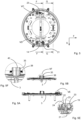
- The child seat vehicle according to the invention will further be explained with reference to the drawings, wherein,
-
figure 1 is an exploded perspective view of a first embodiment of a child vehicle seat according to the invention, -
figure 2 is a half-exploded and half assembled perspective view of the child vehicle seat as shown infigure 1 , -
figure 3 is an assembled perspective view of a rotating part and a base of the child vehicle seat as shown infigure 1 , with the rotating part being locked to the base, -
figure 3A is an enlarged view of detail IIIA offigure 3 , -
figure 4 is an exploded perspective view of a part of first locking means of child vehicle seat as shown infigure 1 , -
figure 5 is a top view offigure 3 , -
figure 5A is a cross-sectional view along line F-F offigure 5 , -
figure 5B is across-sectional view along line G-G offigure 5 , -
figure 5C is an enlarged view of detail VC shown infigure 5 , -
figure 5D is an enlarged view of detail VD shown infigure 5 , -
figure 5E is an enlarged view of detail VE shown infigure 5A , -
figure 5F is an enlarged view of detail VF shown infigure 5B , -
figure 6 is an assembled perspective view of a rotating part and a base of the child vehicle seat as shown infigure 1 , with the rotating part being locked to the base, in a rotated position, -
figure 6A is an enlarged view of detail VIA shown infigure 6 , -
figure 7 is a top view offigure 6 , -
figure 7A is across-sectional view along line C-C offigure 7 , -
figure 7B is an enlarged view of detail VIIB shown infigure 7A , -
figure 7C is a cross-sectional view along line D-D offigure 7 , -
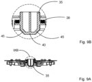
figure 8 is an assembled perspective view of a sliding part of the child vehicle seat as shown infigure 1 , the sliding part being locked in an unsliding-out position, -
figure 9 is a top view offigure 8 , -
figure 9A is a cross-sectional view along line E-E offigure 9 , -
figure 9B is an enlarged view of detail VIIB shown infigure 9A , -
figure 10 is an assembled perspective view of the sliding part, the sliding part being locked in an intermediate position, -
figure 11 is an exploded perspective view of detail XI offigure 10 , showing a first embodiment of a pen-dent mechanism of the child vehicle seat, -
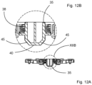
figure 12 is a top view offigure 10 , -
figure 12A is across-sectional view along line H-H offigure 12 , -
figure 12B is an enlarged view of detail XIIB shown infigure 12A , -
figure 12C is a cross-sectional view along line I-I offigure 12 , -
figure 12D is an enlarged view of detail XIID shown infigure 12C , -
figure 12E is a cross-sectional view along line J-J offigure 12 , -
figure 12F is an enlarged view of detail XIIF shown infigure 12E , -
figure 13 is an exploded perspective view of detail XIVA offigure 14 , showing a second embodiment of a pen-dent mechanism of the child vehicle seat, -
figure 14 is a cross-sectional view of the sliding part with a second embodiment of a pen-dent mechanism of the child vehicle seat, -
figure 14A is an enlarged view of detail XIVA shown infigure 14 , -
figure 15 is an exploded perspective view of a child seat unlocking means of the child vehicle seat as shown infigure 1 , -
figure 15A is an enlarged view of detail XVA shown infigure 15 , -
figure 15B is an enlarged view of detail XVB shown infigure 15 -
figure 16 is an assembled perspective view of the child seat unlocking means as shown infigure 15 , in which the child seat unlocking means being in locked state, -
figure 16A is an enlarged view of detail XVIA shown infigure 16 , -
figure 16B is an enlarged view of detail XVIB shown infigure 16 , -
figure 16C is an enlarged view of detail XVIC shown infigure 16 , -
figure 17 is an assembled perspective view of the child seat unlocking means, in which child seat unlocking means being in unlocked state, -
figure 17A is an enlarged view of detail XVIIA shown infigure 17 , -
figure 17B is an enlarged view of detail XVIIB shown infigure 17 , -
figure 17C is an enlarged view of detail XVIIC shown infigure 17 , -
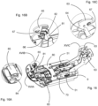
figure 18 is perspective view of the child vehicle seat as shown infigure 1 , in which the child vehicle seat being in a forward facing position, -
figure 19 is perspective view of the child vehicle seat as shown infigure 1 , in which the child vehicle seat being in a side facing position, -
figure 20 is perspective view of the child vehicle seat as shown infigure 1 , in which the child vehicle seat being in a side facing position, whereby the sliding part is in an sliding-out position, -
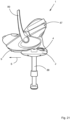
figure 21 is a front view of a child vehicle seat seen in a direction opposite to the driving direction of the vehicle, whereby a first kind of child seat is in a side facing position, -
figure 22 is a front view of a child vehicle seat seen in a direction opposite to the driving direction of the vehicle, whereby a second kind of child seat is in a side facing position. - In the drawings, like reference numerals refer to like elements.
- The
figures 1-22 show achild vehicle seat 1 according to the invention. Thechild vehicle seat 1 comprises a base 2 (seefigures 18-22 ) detachably connectable to a vehicle seat. Infigure 1 only abase plate 3 of thebase 2 is shown. Thebase plate 3 is fixed to thebase 2. - The
child vehicle seat 1 further comprises arotating part 4 being rotatable with respect to thebase 2 about arotation axis 5 from a forward facing position as shown infigure 18 seen in a driving direction F of the vehicle in use to a side facing position as shown in thefigures 18 ,19 directed to in a sliding direction S towards a door of the vehicle to a rearward facing position and to a side facing position directed to another door of the vehicle. The sliding direction S extends substantially perpendicular to the driving direction F. Therotating part 4 comprisesbottom plate 6, atop plate 7 and a guidingplate 8 located between thebottom plate 6 and thetop plate 7. - The
child vehicle seat 1 further comprises a slidingpart 9 being slidable with respect to the guidingplate 8 of therotating part 4. As will be explained here below, the slidingpart 9 being slidable with respect to the guidingplate 8 in the sliding direction S, when therotating part 4 is being rotated to one of the side facing positions directed to one of the doors of the vehicle. - Mounted on top of the sliding
part 7 is a mountingelement 10 for detachable holding a child seat. For the sake of clarity, the child seat is not shown in thefigures 1-20 but only in thefigures 21 and22 . -
Figure 1 show thebase plate 3, therotating part 4 rotatably connected on top of thebase plate 3 and the slidingpart 7 being slidable connected on top of therotating part 4. Thechild vehicle seat 1 comprises first locking means 11 to detachably lock the rotating part to thebase 2 in the forward facing position and the rearward facing position. Thechild vehicle seat 1 also comprises second locking means to detachably lock sliding of the slidingpart 9 with respect to therotating part 4. - As will be further explained here below, unlocking of the first locking means 11 enable the
rotating part 4 together with the slidingpart 9, the mountingelement 10 and the child seat to rotate about therotation axis 5. Near or at the side facing positions the second locking means will be automatically unlocked to allow the slidingpart 9, the mountingelement 10 and the child seat to slide in the sliding direction S. - The first locking means 11 comprises a first and
second handle child vehicle seat 1. Thehandle 12 is provided with a connectingpiece 14 being pivotable about pivot axis 15 (fig. 5D ) in a direction indicated by arrow P1. Anend 16 of connectingpiece 14 is pivotably connected to afirst end 17 of alongitudinal rod 18 extending to theother handle 13. Also connected to thisfirst end 17 is aholder 19. Theholder 19 is provided with twoslots 20 extending under an angle with the vertical and horizontal. A vertically extending lockingpen 21 is located between theslots 20. Ahorizontal pen 22 extends through the lockingpen 21 and is slidably located in theslots 20. The horizontal pen is further slidably located in a vertically extendingslot 23 of abracket 24. Thebracket 24 is fixed to thebottom plate 6 of therotating part 4. - As can be seen in
figure 5C , thehandle 13 is provided with a connectingpiece 25 being pivotable in a direction indicated by arrow P2. The connectingpiece 25 is connected to alever 26. Thelever 26 is pivotable about apivot axis 27 in a direction indicated by arrow P3. Anend 28 of thelever 26 is pivotably connected to asecond end 29 of thelongitudinal rod 18 extending to theother handle 12. - By actuating the
handle 12 or thehandle 13, the connectingpieces longitudinal rod 18 will be moved in the direction as indicated by arrow P4. When moving thelongitudinal rod 18 in the direction as indicated by arrow P4, theholder 19 will be moved in this direction as well. Thehorizontal pen 22 will slide in theslots 20 in upward direction as indicated by arrow P5 whereby the vertically extending lockingpen 21 will be moved upwardly as well. Before moving upwardly, the end of the lockingpen 21 is located in one of two lockingholes 30 of thebottom plate 6 of thebase 2, thereby locking therotating part 4 to thebase 2. By moving the lockingpen 21 out of the lockinghole 30, therotating part 4 is being unlocked from thebase 2 and can be rotated about therotation axis 5 in the direction as indicated by arrow P20. - One of the locking holes 30 is used to lock the
rotating part 4 to thebase 2 in a forward facing position of the child seat whilst the other lockinghole 30 is being used to lock therotating part 4 to thebase 2 in a rearward facing position of the child seat. - The second locking means comprises two
engagement elements 35 extending throughopenings 36 in thebottom plate 6 and theopenings 37 in the guidingplate 8. Theengagement elements 35 are pressed in the direction of thebase plate 3 by means ofsprings 38, whereby the bottom 40 of theengagement element 35 is located against thebaseplate 3. Upper parts of theengagement elements 35 are located in engagement holes 41 of the slidingpart 9 thereby locking the slidingpart 9 to thebottom plate 6 and the guidingplate 8 of therotating part 4. - When the
rotating part 4 is being rotated with respect to thebase plate 3, the bottom 40 of theengagement elements 35 will slide over thebase plate 3 until theengagement elements 35 will reachengagement holes 42 of thebase plate 3. As soon as theengagement elements 35 reach the engagement holes 42 of thebase plate 3, theengagement elements 35 will be moved under spring force ofsprings 38 into the engagement holes 42, thereby locking therotating part 4 to thebase 4, moving out of the engagement holes 41 of the slidingpart 9 and unlocking the slidingpart 9 from therotating part 4. - The
rotating part 4 will be locked to the base in a position whereby the child seat is in one of the two side facing directions. - In the shown embodiment, the
engagement elements 35 are located opposite to each other in a line being substantially perpendicular to thelongitudinal rod 18. Due to this orientation, the locking holes 30 and the engagement holes 42 of thebase plate 3 are located closely together. However, other arrangements are also possible. - In the shown embodiment the engagement holes 42 have the same dimensions as the bottom 40 of the
engagement elements 35 so that theengagement element 35 fits nicely in theengagement hole 42. Sides of the bottom 40 are provided withsloped parts 45 as are the engagement holes 42. Due to the slopedparts 45 theengagement elements 35 can easily be moved out of the engagement holes 42 against spring force of thesprings 38 when therotating part 4 is being rotated again with respect to thebase 2. - If desired the
engagement hole 42 may be longer in the direction of rotation of therotating part 4 than theengagement element 35 so that therotating part 4 can slightly rotate with respect to thebase 2 in the side facing position over a predetermined angle being between 0 and 20 degrees, more preferably 10 degrees. - The guiding
part 8 is provided withbearings 46, seefigures 12C and 12D to facilitate the sliding of the slidingpart 9 with respect to the guidingpart 8, thebearings 46 can be ball bearings or roller bearings. Due to thebearings 46 the force to move the slidingpart 9 with respect to the guidingpart 8 is relative low which is very convenient during sliding of the slidingpart 9. - However, when a parent wants to remove the child from the child seat, remove the child seat from the mounting
element 10 or place the child back into the child seat or place the child seat back onto the mounting element 10 a more firm connection between the slidingpart 9 and the guidingpart 8 would be appreciated so that the slidingpart 9 will not or nearly not move with respect to the guidingpart 8. Such a more firm connection is realized by the child seat at a start position as shown infigure 8 , a number of intermediate positions (one as shown infigures 10, 12 ) and an end position of the slidingpart 9 with respect to the guidingpart 8. The end position is the position wherein the slidingpart 9 has slit as far as possible with respect to the guidingpart 8. At the start position the slidingpart 9 is located completely above the guidingpart 8. - To define the start position, in this embodiment three intermediate positions and the end position, the guiding
plate 8 is at each position provided with two rows ofdents figures 1 ,2 ). Thedents 48 define the start position, thedents 49 the three different intermediate positions and thedents 50 the end positions. - More or less intermediate positions can be realised by removing or covering dents or by adding dents.
- To softly lock the sliding
part 9 with respect to the guidingpart 8 at thedents part 9 is provided with twoholders 51 mounted on top of the slidingpart 9. Eachholder 51 comprises apen 52 and aspring 53 located between a top of thepen 52 and theholder 51. The lower end of thepen 52 rests under spring force of thespring 53 against the top surface of the guidingpart 8 and is located on a line extending through thedents - By the embodiment as shown in
figures 11 ,12E, 12F , thelower end 54 of thepen 52 comprises on two opposite sides inclinedsurfaces 55 so that thelower end 54 is frustoconical shaped. By the embodiment of as shown infigures 12E, 12F thedents 49 at the intermediate positions have inclinedsurfaces 56 defining an angle A1 between them, whilst thedent surfaces 57 defining an angle A2 between them, whereby angle A2 is smaller than angle A1. So the dents are frustoconical shaped. When moving the slidingpart 9 with respect to the guidingpart 8 in or opposite to the direction as indicted by arrow P6, thelower end 54 will slide over the top surface of the guidingpart 8 until thelower end 54 will reach adent pen 52 will be moved under spring force ofspring 53 into thedent part 9 with a relatively low force, thepens 52 located in the corresponding dents 48, 49, 50 will prevent the slidingpart 9 to slide with respect to the guidingpart 8. However, as soon as the person pushes or pulls on the slidingpart 9 with a larger force, thereby overcoming the predetermined spring force ofsprings 53, theinclined surfaces 55 of thepens 52 will slide over the incised surfaces 56, 57 of thedents pens 52 out of thedents 50 with the smaller angle A1 than out at thedents 49 with the larger angle A1. The angles A1, A2 are preferably between 60-140 degrees and can be made as small or as larger as desired. It is also possible to have the same angle A1, A2 at eachdent - By the embodiment as shown in
figures 13, 14 ,15 , thelower end 54 of thepen 52 has arounded end 58 being located in a hemisphere shapeddent -
Figures 15-17 show the mountingelement 10 of thechild vehicle seat 1. The mountingelement 10 comprises three main parts as shown infigure 15 . The lower part is mounted on the slidingpart 9. It comprises arear part 61 and afront part 62. Therear part 61 comprises twohooks 63 being pivotable under spring force in the direction as indicated by arrow P7 about pivot axes 64. Thefront part 62 comprises twohooks 65 being pivotable under spring force in the direction as indicated by arrow P8 about pivot axes 66. Thehooks 63 pivot in opposite direction to thehooks 65. Eachhook recess 67 to receive a rod mounted on the lower side of the child seat. Such rods are commonly known and not shown here. - A middle part forms a
slide 70 being slidable in and opposite to the direction as indicated by arrow P9. Theslide 70 is pressed under spring force ofspring 71 in the direction opposite to arrow P9. At a rear end theslide 70 is provided with twopens 72 being in abutment withsurfaces 73 of thehooks 63 when thehooks 63 are being moved against spring force in the direction opposite to arrow P7. Theslide 70 is at the rear end also provided with anactuation button 74 to be actuated to push theslide 70 in the direction as indicated by arrow P9. - At the centre the
slide 70 is proved with twolevers 75, eachlever 75 being pivotable connected at oneend 76 to theslide 70, in the middle pivotable aboutpivot axis 77 connected to the slidingpart 9 and at theother end 78 pivotable connected to anadditional slide 80. - The
additional slide 80 forms the third and upper part. At a front end theadditional slide 80 is provided with twopens 81 being in abutment withsurfaces 82 of thehooks 65 when thehooks 65 are being moved against spring force in the direction opposite to arrow P8. - When the
slide 70 is being moved in the direction indicated by arrow P9, thelevers 75 will pivot about the pivot axes 77 in the direction as indicated by arrows P10, P11, thereby forcing theadditional slide 80 to slide in the direction as indicated by arrow P12. By moving theslide 70 and theadditional slide 80, thepens surfaces hooks element 10. - The
slide 70 can be moved in the direction indicated by arrow P9, either by pushing on theactuation button 74 at the rear side of thechild vehicle seat 1 or pulling on ahandle 83 of theslide 70 at the front side of thechild vehicle seat 1. - At the front side of the
slide 70 at least one vertically extendingrod 84 is located. Therod 84 cooperates with anindication knob 85. Theindication knob 85 is pivotable about apivot axis 86 against spring force in the direction as indicated by arrow P13 byrod 84. - When the
hooks figure 16-16C ) receiving the rods of the child seat in the recesses 67 a part of theindication knob 85 is visible through an opening in a cover (not shown) of the child vehicle seat, having for example a green colour. The green colour indicates that all the hooks are closed. - When the
hooks figure 17-17C ), releasing the rods of the child seat from therecesses 67 another part of theindication knob 85 is visible through an opening in the cover (not shown) of the child vehicle seat, having for example a red colour. The red colour indicates that the hooks are not closed. - In a crash the
slide 70 wants to move forward with respect to the slidingpart 9 due to inertia, whereby thehooks 63 might undesirably release the child seat. Due to the fact that in such a case theadditional slide 80 will also moves forward due to inertia, it will keep thehooks 65 and thus also thehooks 63 closed. Both the weight of both movable parts as well as the dimensions of thelevers 75 will define this balance so that in case of a crash thehooks -
Figure 21 shows a front view of thechild vehicle seat 1 seen in a direction opposite to the driving direction of the vehicle with a first kind ofchild seat 87. Thechild seat 87 is in a side facing position. Thechild seat 87 is detachable connected to the slidingpart 9. The slidingpart 9 is located on top of therotating part 4. Therotating part 4 is located on top of thebase 2. Thebase 2 is provided with asupport leg 88 resting with its lower end on a floor of the vehicle. Thechild seat 87 can be lifted of the slidingpart 9 by means of ahandle 89. At the bottom side thechild seat 87 is provided with rods cooperating with thehooks -
Figure 22 shows a front view of thechild vehicle seat 1 seen in a direction opposite to the driving direction of the vehicle with a second kind ofchild seat 90. Thechild seat 90 is in a side facing position. Thechild seat 90 can be detachable connected or being fixed to the slidingpart 9. The slidingpart 9 is located on top of therotating part 4. Therotating part 4 is located on top of thebase 2. Thebase 2 is provided with asupport leg 88 resting with its lower end on a floor of the vehicle. In case that thechild seat 90 is removable connected to the slidingpart 9, the bottom side of thechild seat 90 is provided with rods cooperating with thehooks child seat 87 and thechild seat 90 can be used in the samechild vehicle seat 1. - Since the
child seat 90 is intended for larger children, whereby the child can leave thechild seat 90 by itself so that it is also possible to have thechild seat 90 being fixed to theslide 9. This has the advantage that no mechanism withhooks - According to EU regulations the child vehicle seat together with the child might be maximum 33 kg, meaning that with a child of 18 kg at an age of 4 years old, the child vehicle seat may not exceed 15 kg.
- It is also possible to use the bearing elements by other embodiments of child vehicle seats whereby for example the rotating part is mounted on top of the sliding part.
- It is also possible to have the dents on the sliding part and the pen cooperating mounted with the dents on the guiding part.
- It is also possible to use other first locking elements well known in the art, like the one as described
US7984946B1 . - It is also possible to have engagement holes at for example 45 degrees in each direction seen from the forward facing direction. This might be advantageous by vehicles comprising only two front doors and no rear doors. By locking the rotating part at 45 degrees, the sliding part and the child seat attached thereto can be moved in the direction to the nearest front door.
- It is also possible to use the first locking element to lock the rotating part to the base for example in the side facing position or in the 45 degrees positions.
- It is also possible to use the mechanism for let the sliding part overcome a predetermined force before being able to slide from its current position to a next position, by other sliding parts of child vehicle seats, for example not provided with a rotating part.
- It is also possible that the child seat is fixed to the sliding part and can not be removed thereof.
- It is also possible to let the
hooks slide 70. - It is also possible to use the unlocking means located on the front side as well as on the rear side of the child vehicle seat, by other kind of child vehicle seats not provided with a rotating part and/or a sliding part.
- It is also possible to use the movable part and/or the additional movable part by other kind of child vehicle seats not provided with a rotating part and/or a sliding part.
-
- 1 child vehicle seat
- 2 base
- 3 base plate
- 4 rotating part
- 5 rotation axis
- 6 bottom plate
- 7 top plate
- 8 guiding plate
- 9 sliding part
- 10 mounting element
- 11 first locking means
- 12 first handle
- 13 second handle
- 14 connecting piece
- 15 pivot axis
- 16 end
- 17 first end
- 18 longitudinal rod
- 19 holder
- 20 slot
- 21 locking pen
- 22 horizontal pen
- 23 vertically extending slot
- 24 bracket
- 25 connecting piece
- 26 lever
- 27 pivot axis
- 28 end
- 29 second end
- 30 locking hole
- 35 engagement element
- 36 opening
- 37 opening
- 38 spring
- 40 bottom
- 41 engagement hole
- 42 engagement hole
- 45 sloped part
- 46 bearing
- 48 dent
- 49 dent
- 50 dent
- 51 holder
- 52 pen
- 53 spring
- 54 lower end
- 55 inclined surface
- 56 inclined surface
- 57 inclined surface
- 58 rounded end
- 61 rear part
- 62 front part
- 63 hook
- 64 pivot axis
- 65 hook
- 66 pivot axis
- 67 recess
- 70 slide
- 71 spring
- 72 pen
- 73 surface
- 74 actuation button
- 75 lever
- 76 end
- 77 pivot axis
- 78 end
- 80 additional slide
- 81 pen
- 82 surface
- 83 handle
- 84 rod
- 85 indication knob
- 86 pivot axis
- 87 child seat
- 88 support rod
- 89 handle
- 90 87 child seat
- A1 angle
- A2 angle
- F driving direction
- S sliding direction
- P1 arrow
- P2 arrow
- P3 arrow
- P4 arrow
- P5 arrow
- P6 arrow
- P7 arrow
- P8 arrow
- P9 arrow
- P10 arrow
- P11 arrow
- P12 arrow
- P13 arrow
- P20 arrow
Claims (18)
- A child vehicle seat (1) comprising a base (2) detachably connectable to a vehicle seat, a rotating part (4) being rotatable with respect to the base (2) about a rotation axis (5) from at least a forward facing position or a rearward facing position seen in a driving directing of the vehicle in use to a side facing position directed to a door of the vehicle and vice versa, a sliding part (9) being slidable with respect to the base (2) in a sliding direction (S) substantially perpendicular to the driving direction (F) of the vehicle, a child seat connected to the base (2) via the sliding part (9) and the rotating part (4), characterized in that the child seat and the sliding part (9) are slidable together with respect to the rotating part (4), wherein the child vehicle seat (1) comprises first locking means (11) to detachably lock the rotating part (4) to the base (2) in the at least forward facing position or rearward facing position, as well as second locking means to detachably lock sliding of the sliding part (9) with respect to the rotating part (4).
- A child vehicle seat (1) according to claim 1, characterized in that by unlocking the first locking means (11) the rotating part (4) together with the sliding part (9) and child seat are rotatable to the side facing position, whereby near or at the side facing position the second locking means will be automatically unlocked to allow the sliding part (9) together with the child seat to slide in the sliding direction (S).
- A child vehicle seat (1) according to claim 1 or 2, characterized in that the first locking means (11) comprises a first and second handle (13) located on opposite sides of the child vehicle seat (1), whereby a locking pen (21) is moved out of a locking hole (30) by moving the first handle (12) in clockwise direction about the rotation axis (5) or moving the second handle (13) in counter clockwise direction about the rotation axis (5).
- A child vehicle seat (1) according to claim 3, characterized in that the locking pen (21) is movable connected to the rotating part (4), whilst the locking hole (30) is located in the base (2).
- A child vehicle seat (1) according to one of the preceding claims, characterized in that the first locking means (11) detachably lock the rotating part (4) to the base (2) in the at least forward facing position as well as the rearward facing position.
- A child vehicle seat (1) according to one of the preceding claims, characterized in that the second locking means comprises at least one engagement element movably extending through an opening (36, 37) in the rotating part (4), which engagement element is movable through the opening (36, 37) from a first position wherein the engagement element is located in an engagement hole (41, 42) of the sliding part (9) and the opening (36, 37) to lock the sliding part (9) with respect to the rotatable part, to a second position wherein the engagement element is located in an engagement hole (41, 42) of the base (2) and the opening (36, 37) to limit rotation of the rotatable part with respect to the base (2) to a predetermined angle.
- A child vehicle seat (1) according to claim 6, characterized in that the predetermined angle is in the range from zero degrees to 20 degrees, more preferably 10 degrees.
- A child vehicle seat (1) according to one of the preceding claims, characterized in that the sliding part (9) is slidable in the sliding direction (S) from a start position via at least one intermediate position to an end position.
- A child vehicle seat (1) according to claim 8, characterized in that at least at one of the start position, the at least one intermediate position or the end position, the sliding part (9) must overcome a predetermined force before being able to slide from its current position to a next position.
- A child vehicle seat (1) according to claim 9, characterized in that the sliding part (9) or the rotating part (4) is provided with a pen (52, 72, 81) being located under the predetermined spring force in a dent (48, 49, 50) located in the other of the sliding part (9) or the rotating part (4).
- A child vehicle seat (1) according to claim 10, characterized in that the pen (52, 72, 81) has a rounded end (58) being located in a hemisphere shaped dent (48, 49, 50).
- A child vehicle seat (1) according to claim 10, characterized in that the pen (52, 72, 81) has a frustoconical shaped end being located in a frustoconical shaped dent (48, 49, 50).
- A child vehicle seat (1) according to claim 12, characterized in that the frustoconical shaped dent (48, 49, 50) has inclined walls, having different angles (A1, A2) at opposite sides of the dent (48, 49, 50).
- A child vehicle seat (1) according to claim 12, characterized in that the frustoconical shaped dents (48, 49, 50) have inclined walls, having different angles (A1, A2) at the start position, the at least one intermediate position and/or the end position.
- A child vehicle seat (1) according to one of the preceding claims, characterized in that the child seat is detachably connected to the sliding part (9), whereby the child vehicle seat (1) is provided with unlocking means to unlock the connection between the child seat and the sliding part (9), which unlocking means are located on a front side as well as on the rear side of the child vehicle seat (1).
- A child vehicle seat (1) according to claim 15, characterized in that the sliding part (9) is provided with pivotable hooks (63, 65) being connectable to connecting elements of the child seat, whereby the hooks (63, 65) are movable against spring force by means of a movable part to an open position wherein the child seat can be removed from the sliding part (9), which movable part extends from the front side to the rear side of the child vehicle seat (1).
- A child vehicle seat (1) according to claim 16, characterized in that the movable part is provided with an additional movable part being movable in opposite direction as the movable part, whereby a first set of hooks (63, 65) is pivotable by means of the movable part in a first direction, whilst a second set of hooks (63, 65) is pivotable by means of the additional movable part in a second direction being opposite to the first direction.
- A base (2) suitable for a child vehicle set according to one of the preceding claims, which base (2) being detachably connectable to a vehicle seat, said base (2) comprises a rotating part (4) being rotatable with respect to the base (2) about a rotation axis (5) from at least a forward facing position or a rearward facing position seen in a driving directing of the vehicle in use to a side facing position directed to a door of the vehicle and vice versa, a sliding part (9) being slidable with respect to the base (2) in a sliding direction (S) substantially perpendicular to the driving direction (F) of the vehicle, wherein the sliding part (9) is slidable with respect to the rotating part (4), wherein the child vehicle seat (1) comprises first locking means (11) to detachably lock the rotating part (4) to the base (2) in the at least forward facing position or rearward facing position, as well as second locking means to detachably lock sliding of the sliding part (9) with respect to the rotating part (4).
Priority Applications (10)
| Application Number | Priority Date | Filing Date | Title |
|---|---|---|---|
| EP23156275.2A EP4414213A1 (en) | 2023-02-13 | 2023-02-13 | A child vehicle seat as well as a base suitable for such a child vehicle seat |
| DE202023100761.9U DE202023100761U1 (en) | 2023-02-13 | 2023-02-16 | Infant vehicle seat and base suitable therefor |
| CN202421087952.7U CN222886327U (en) | 2023-02-13 | 2024-02-08 | Locking device for child carrier base |
| CN202421087966.9U CN222875815U (en) | 2023-02-13 | 2024-02-08 | Detachable connecting structure between child carrier base and carrier body |
| CN202420294173.8U CN221969418U (en) | 2023-02-13 | 2024-02-08 | Child carrier base and child carrier comprising the child carrier base |
| CN202421087979.6U CN222886328U (en) | 2023-02-13 | 2024-02-08 | Head locking mechanism of child carrier base |
| CN202410617127.1A CN118665289A (en) | 2023-02-13 | 2024-02-08 | Locking device for child carrier base |
| CN202410176609.8A CN117962711A (en) | 2023-02-13 | 2024-02-08 | Child carrier base and carrier including the same |
| US18/439,112 US20240270132A1 (en) | 2023-02-13 | 2024-02-12 | Juvenile restraint |
| AU2024200902A AU2024200902A1 (en) | 2023-02-13 | 2024-02-13 | A child vehicle seat as well as a base suitable for such a child vehicle seat |
Applications Claiming Priority (1)
| Application Number | Priority Date | Filing Date | Title |
|---|---|---|---|
| EP23156275.2A EP4414213A1 (en) | 2023-02-13 | 2023-02-13 | A child vehicle seat as well as a base suitable for such a child vehicle seat |
Publications (1)
| Publication Number | Publication Date |
|---|---|
| EP4414213A1 true EP4414213A1 (en) | 2024-08-14 |
Family
ID=85227308
Family Applications (1)
| Application Number | Title | Priority Date | Filing Date |
|---|---|---|---|
| EP23156275.2A Pending EP4414213A1 (en) | 2023-02-13 | 2023-02-13 | A child vehicle seat as well as a base suitable for such a child vehicle seat |
Country Status (5)
| Country | Link |
|---|---|
| US (1) | US20240270132A1 (en) |
| EP (1) | EP4414213A1 (en) |
| CN (6) | CN222886328U (en) |
| AU (1) | AU2024200902A1 (en) |
| DE (1) | DE202023100761U1 (en) |
Families Citing this family (8)
| Publication number | Priority date | Publication date | Assignee | Title |
|---|---|---|---|---|
| CN119189818A (en) * | 2020-12-11 | 2024-12-27 | 宝钜瑞士股份有限公司 | Child safety seats and seat bases |
| US12311809B2 (en) * | 2022-04-25 | 2025-05-27 | Kioma, Inc. | Child safety seat |
| US20240375561A1 (en) * | 2023-05-10 | 2024-11-14 | Dorel Juvenile Group, Inc. | Child restraint |
| US20250135966A1 (en) * | 2023-10-25 | 2025-05-01 | Dorel Juvenile Group, Inc. | Child restraint |
| WO2025096573A1 (en) * | 2023-10-31 | 2025-05-08 | Britax Child Safety, Inc. | Child car seat ellipsoidal path system |
| CN121375594A (en) * | 2024-01-31 | 2026-01-23 | 台前县永佳羽毛制品有限公司 | Control mechanism of multifunctional seat adjusting mechanism and child safety seat thereof |
| EP4660003A1 (en) * | 2024-06-06 | 2025-12-10 | Maxi Miliaan B.V. | A child vehicle seat as well as a base suitable for such a child vehicle seat |
| CN222921423U (en) * | 2024-08-30 | 2025-05-30 | 麦克英孚(宁波)婴童用品有限公司 | A lateral translation seat positioning structure and a child safety seat |
Citations (4)
| Publication number | Priority date | Publication date | Assignee | Title |
|---|---|---|---|---|
| WO2005000627A1 (en) * | 2003-06-25 | 2005-01-06 | Catalyst Developments (Europe) Limited | Child safety seat |
| CN201745451U (en) * | 2010-06-25 | 2011-02-16 | 好孩子儿童用品有限公司 | Child car seat |
| EP2308716A1 (en) * | 2008-07-02 | 2011-04-13 | Combi Corporation | Child seat |
| US7984946B2 (en) | 2007-07-24 | 2011-07-26 | Chirine M Zahar | Automotive vehicle safety seat |
-
2023
- 2023-02-13 EP EP23156275.2A patent/EP4414213A1/en active Pending
- 2023-02-16 DE DE202023100761.9U patent/DE202023100761U1/en active Active
-
2024
- 2024-02-08 CN CN202421087979.6U patent/CN222886328U/en active Active
- 2024-02-08 CN CN202421087966.9U patent/CN222875815U/en active Active
- 2024-02-08 CN CN202420294173.8U patent/CN221969418U/en active Active
- 2024-02-08 CN CN202410176609.8A patent/CN117962711A/en active Pending
- 2024-02-08 CN CN202421087952.7U patent/CN222886327U/en active Active
- 2024-02-08 CN CN202410617127.1A patent/CN118665289A/en active Pending
- 2024-02-12 US US18/439,112 patent/US20240270132A1/en active Pending
- 2024-02-13 AU AU2024200902A patent/AU2024200902A1/en active Pending
Patent Citations (4)
| Publication number | Priority date | Publication date | Assignee | Title |
|---|---|---|---|---|
| WO2005000627A1 (en) * | 2003-06-25 | 2005-01-06 | Catalyst Developments (Europe) Limited | Child safety seat |
| US7984946B2 (en) | 2007-07-24 | 2011-07-26 | Chirine M Zahar | Automotive vehicle safety seat |
| EP2308716A1 (en) * | 2008-07-02 | 2011-04-13 | Combi Corporation | Child seat |
| CN201745451U (en) * | 2010-06-25 | 2011-02-16 | 好孩子儿童用品有限公司 | Child car seat |
Also Published As
| Publication number | Publication date |
|---|---|
| CN222875815U (en) | 2025-05-16 |
| AU2024200902A1 (en) | 2024-08-29 |
| US20240270132A1 (en) | 2024-08-15 |
| DE202023100761U1 (en) | 2023-06-13 |
| CN117962711A (en) | 2024-05-03 |
| CN221969418U (en) | 2024-11-08 |
| CN222886328U (en) | 2025-05-20 |
| CN222886327U (en) | 2025-05-20 |
| CN118665289A (en) | 2024-09-20 |
Similar Documents
| Publication | Publication Date | Title |
|---|---|---|
| EP4414213A1 (en) | A child vehicle seat as well as a base suitable for such a child vehicle seat | |
| US7040684B2 (en) | Easy entry seat with seat back mounted floor latch | |
| US6739668B2 (en) | Vehicle seat hinge mechanism with reclining with forward dumping, memory return and fold-flat functionality | |
| US6695405B2 (en) | Seat device including a fold-down back | |
| KR20230064716A (en) | Device for adjusting seat of vehicle | |
| US5702145A (en) | Folding second seat with seat track release latch mechanism | |
| CN111278677A (en) | Child seat system including seat element and base mountable on vehicle seat | |
| US20050225144A1 (en) | Neck rest for seats of automobiles | |
| JPH0867186A (en) | Vehicle seat device | |
| JP2698973B2 (en) | Removable rear seats for cars | |
| CN114572069A (en) | Vehicle seat with tiltable seat bottom and seat back for improved rear row position | |
| EP3782909B1 (en) | End bay assembly with deployable step and deployable step constructions | |
| CN104039590B (en) | Locking and gradient adjustment component | |
| CN107380020A (en) | Child's chair | |
| JPH0512263U (en) | Vehicle seat | |
| JP4260570B2 (en) | Vehicle seat device | |
| JPH11113669A (en) | Car seat | |
| JP2018114836A (en) | Vehicle slide rail device | |
| CN220639611U (en) | Base, holding mechanism, crotch buckle storage device, and child safety seat | |
| JP3892658B2 (en) | Folding seat for vehicle | |
| EP4660003A1 (en) | A child vehicle seat as well as a base suitable for such a child vehicle seat | |
| KR100622699B1 (en) | Walk-in device for vehicle seat | |
| KR200369656Y1 (en) | Rear seat cushion titling assembly for an automobile | |
| JP6213377B2 (en) | Tilt sheet | |
| EP4711274A1 (en) | Seat armrest locking mechanism |
Legal Events
| Date | Code | Title | Description |
|---|---|---|---|
| PUAI | Public reference made under article 153(3) epc to a published international application that has entered the european phase |
Free format text: ORIGINAL CODE: 0009012 |
|
| STAA | Information on the status of an ep patent application or granted ep patent |
Free format text: STATUS: REQUEST FOR EXAMINATION WAS MADE |
|
| 17P | Request for examination filed |
Effective date: 20240215 |
|
| AK | Designated contracting states |
Kind code of ref document: A1 Designated state(s): AL AT BE BG CH CY CZ DE DK EE ES FI FR GB GR HR HU IE IS IT LI LT LU LV MC ME MK MT NL NO PL PT RO RS SE SI SK SM TR |
|
| P01 | Opt-out of the competence of the unified patent court (upc) registered |
Free format text: CASE NUMBER: APP_67460/2024 Effective date: 20241220 |
|
| GRAP | Despatch of communication of intention to grant a patent |
Free format text: ORIGINAL CODE: EPIDOSNIGR1 |
|
| STAA | Information on the status of an ep patent application or granted ep patent |
Free format text: STATUS: GRANT OF PATENT IS INTENDED |
|
| INTG | Intention to grant announced |
Effective date: 20250801 |
|
| GRAJ | Information related to disapproval of communication of intention to grant by the applicant or resumption of examination proceedings by the epo deleted |
Free format text: ORIGINAL CODE: EPIDOSDIGR1 |
|
| STAA | Information on the status of an ep patent application or granted ep patent |
Free format text: STATUS: REQUEST FOR EXAMINATION WAS MADE |
|
| INTC | Intention to grant announced (deleted) | ||
| GRAP | Despatch of communication of intention to grant a patent |
Free format text: ORIGINAL CODE: EPIDOSNIGR1 |
|
| STAA | Information on the status of an ep patent application or granted ep patent |
Free format text: STATUS: GRANT OF PATENT IS INTENDED |
|
| INTG | Intention to grant announced |
Effective date: 20260123 |