EP4413957A1 - Zervikaler cage - Google Patents
Zervikaler cage Download PDFInfo
- Publication number
- EP4413957A1 EP4413957A1 EP24155681.0A EP24155681A EP4413957A1 EP 4413957 A1 EP4413957 A1 EP 4413957A1 EP 24155681 A EP24155681 A EP 24155681A EP 4413957 A1 EP4413957 A1 EP 4413957A1
- Authority
- EP
- European Patent Office
- Prior art keywords
- cage
- cap
- thread
- passages
- designed
- Prior art date
- Legal status (The legal status is an assumption and is not a legal conclusion. Google has not performed a legal analysis and makes no representation as to the accuracy of the status listed.)
- Granted
Links
Images



Classifications
-
- A—HUMAN NECESSITIES
- A61—MEDICAL OR VETERINARY SCIENCE; HYGIENE
- A61F—FILTERS IMPLANTABLE INTO BLOOD VESSELS; PROSTHESES; DEVICES PROVIDING PATENCY TO, OR PREVENTING COLLAPSING OF, TUBULAR STRUCTURES OF THE BODY, e.g. STENTS; ORTHOPAEDIC, NURSING OR CONTRACEPTIVE DEVICES; FOMENTATION; TREATMENT OR PROTECTION OF EYES OR EARS; BANDAGES, DRESSINGS OR ABSORBENT PADS; FIRST-AID KITS
- A61F2/00—Filters implantable into blood vessels; Prostheses, i.e. artificial substitutes or replacements for parts of the body; Appliances for connecting them with the body; Devices providing patency to, or preventing collapsing of, tubular structures of the body, e.g. stents
- A61F2/02—Prostheses implantable into the body
- A61F2/30—Joints
-
- A—HUMAN NECESSITIES
- A61—MEDICAL OR VETERINARY SCIENCE; HYGIENE
- A61F—FILTERS IMPLANTABLE INTO BLOOD VESSELS; PROSTHESES; DEVICES PROVIDING PATENCY TO, OR PREVENTING COLLAPSING OF, TUBULAR STRUCTURES OF THE BODY, e.g. STENTS; ORTHOPAEDIC, NURSING OR CONTRACEPTIVE DEVICES; FOMENTATION; TREATMENT OR PROTECTION OF EYES OR EARS; BANDAGES, DRESSINGS OR ABSORBENT PADS; FIRST-AID KITS
- A61F2/00—Filters implantable into blood vessels; Prostheses, i.e. artificial substitutes or replacements for parts of the body; Appliances for connecting them with the body; Devices providing patency to, or preventing collapsing of, tubular structures of the body, e.g. stents
- A61F2/02—Prostheses implantable into the body
- A61F2/30—Joints
- A61F2002/30001—Additional features of subject-matter classified in A61F2/28, A61F2/30 and subgroups thereof
- A61F2002/30316—The prosthesis having different structural features at different locations within the same prosthesis; Connections between prosthetic parts; Special structural features of bone or joint prostheses not otherwise provided for
- A61F2002/30329—Connections or couplings between prosthetic parts, e.g. between modular parts; Connecting elements
- A61F2002/30405—Connections or couplings between prosthetic parts, e.g. between modular parts; Connecting elements made by screwing complementary threads machined on the parts themselves
-
- A—HUMAN NECESSITIES
- A61—MEDICAL OR VETERINARY SCIENCE; HYGIENE
- A61F—FILTERS IMPLANTABLE INTO BLOOD VESSELS; PROSTHESES; DEVICES PROVIDING PATENCY TO, OR PREVENTING COLLAPSING OF, TUBULAR STRUCTURES OF THE BODY, e.g. STENTS; ORTHOPAEDIC, NURSING OR CONTRACEPTIVE DEVICES; FOMENTATION; TREATMENT OR PROTECTION OF EYES OR EARS; BANDAGES, DRESSINGS OR ABSORBENT PADS; FIRST-AID KITS
- A61F2/00—Filters implantable into blood vessels; Prostheses, i.e. artificial substitutes or replacements for parts of the body; Appliances for connecting them with the body; Devices providing patency to, or preventing collapsing of, tubular structures of the body, e.g. stents
- A61F2/02—Prostheses implantable into the body
- A61F2/30—Joints
- A61F2002/30001—Additional features of subject-matter classified in A61F2/28, A61F2/30 and subgroups thereof
- A61F2002/30316—The prosthesis having different structural features at different locations within the same prosthesis; Connections between prosthetic parts; Special structural features of bone or joint prostheses not otherwise provided for
- A61F2002/30329—Connections or couplings between prosthetic parts, e.g. between modular parts; Connecting elements
- A61F2002/30476—Connections or couplings between prosthetic parts, e.g. between modular parts; Connecting elements locked by an additional locking mechanism
- A61F2002/30517—Connections or couplings between prosthetic parts, e.g. between modular parts; Connecting elements locked by an additional locking mechanism using a locking plate
Definitions
- the invention relates to a cage which is designed as an intervertebral disc replacement for the spine.
- the invention relates to a cervical cage.
- So-called cages are used for surgical spinal stabilization. These serve to stiffen two adjacent vertebral bodies and are inserted between the vertebrae instead of the intervertebral disc.
- Such a cage is usually made of metal, especially titanium, or of a plastic such as PEEK. To improve fixation, it is known to screw anchoring screws for cranial and caudal fixation across the cage into the vertebral bodies.
- the cage can also be hollow on the inside so that it can be filled with a bone replacement material.
- the bone replacement material is usually a calcium phosphate material into which natural bone tissue can grow.
- the invention is based on the object of providing a cage which can be used flexibly.
- the object of the invention is already achieved by a cage with a cap according to claim 1.
- the invention relates to a cage which is designed as an intervertebral disc replacement for the spine.
- the invention relates to a cage which is designed for a cervical intervertebral disc replacement.
- the cage comprises at least one receptacle for attaching an application tool.
- the receptacle can be designed in particular as a thread via which the cage can be connected to the application tool.
- the thread can be arranged in particular on a side wall, preferably on an anterior side wall of the cage.
- the cage is held securely in place by the holder and can be inserted by the surgeon after resection of the intervertebral disc between the vertebrae.
- the feedthroughs can include a thread.
- the feedthroughs can be used in particular in conjunction with anchoring screws that have a head thread and are thus connected to the cage in a stable angle at the end of the screwing process.
- the cage includes a cap by means of which the passages for the anchoring screws can be closed.
- the caps prevent bone replacement material from escaping laterally from the cage.
- the holder for the handling tool can, for example, serve as a connection for injecting bone replacement material.
- This can in particular be designed as a thread that extends into the at least partially hollow interior of the cage.
- the caps block lateral leakage of the bone replacement material.
- the passages for the anchoring screws for injecting bone replacement material used.
- one opening can be closed with a cap and the bone replacement material can be injected through the other opening.
- Bone replacement material can be introduced above or below the cage in a targeted manner via the openings.
- the cap can be designed in particular as a threaded cap.
- the cap is preferably designed as a grub screw. With such a grub screw, the drive of the screw extends as a blind hole through the thread.
- the cap When inserted, the cap should preferably protrude neither cranially nor caudally from the cage.
- the cap preferably has a conical thread.
- a conical thread has the advantage that the threads engage with each other over a short distance. The screwing in process is therefore quick and requires few turns.
- the cage and cap can be designed in such a way that the cap can be fully screwed in with less than two turns, in particular with 0.3 to 0.5 turns.
- the thread can in particular be designed as a single-turn thread.
- the cap can in particular be truncated cone-shaped.
- the cone angle ⁇ can be between 50 and 30°.
- the cap is preferably designed such that, when inserted, it extends through the passage but does not protrude from the passage.
- the cap when inserted, comprises an inner edge which is flush with the underside or top of the cage.
- the inner edge in the sense of the invention is in particular the distal edge of the cap, i.e. in particular the distal edge of the grub screw.
- this edge When inserted, this edge is approximately at the level of the top or bottom of the cage.
- An outer edge is preferably flush with the side wall of the cage.
- the outer edge is in particular the proximal edge of the cap.
- the inserted cap thus extends over a maximum possible length. Furthermore, a cap with a relatively large diameter can be provided, which in turn makes it possible to provide passages for relatively large locking screws.
- the passages can extend at an angle cranial and/or caudal of 30 to 45° through the cage, relative to its median plane.
- the feedthroughs can extend laterally at an angle of 5 to 15° to a central axis of the cage.
- the cage is made of printed titanium or a titanium alloy.
- the cage can be designed in particular as a cage.
- a grid can extend at least partially over the top or bottom.
- the grid can be penetrated by bone replacement material.
- the grid can in particular, they have the shape of a fabric, i.e. they comprise loops that interlock or wrap around each other. However, these loops are not made of fabric, but of printed titanium or a printed titanium alloy.
- this relates to a cage which is designed as an intervertebral disc replacement for the spine.
- the disclosure relates to the cage described above.
- the cage has two passages which can be used in particular for passing through anchoring screws.
- a spike is provided which sits in at least one passage, preferably in both passages.
- the spike comprises a shaft with a tip.
- the shaft does not have a thread. Instead, the shaft can comprise barbs that anchor the spike in the bone tissue.
- the spike comprises a head thread which is screwed into the thread of the feedthrough.
- the thread can, as described above, be particularly conical.
- the head of the spike can be designed like the cap described above.
- the head thread allows the spike to be guided into the adjacent bone tissue and anchored much more quickly and easily than a screw.
- the spike(s) can be pre-assembled in the cage. It is particularly intended that in the pre-assembled state the tip of the spike does not protrude from the top or bottom of the cage. Only when the head thread is screwed in is the tip guided into the bone, thus anchoring the cage.
- the invention further relates to a set with a cage and cap and/or cage as described above.
- the set further comprises an anchoring screw.
- the screw can in particular have a thread with a shaft which is designed to be screwed into the adjacent vertebral body.
- the anchoring screw preferably comprises a head with a head thread.
- the head thread can in particular correspond to the thread of the cap.
- the anchoring screw is used instead of the cap if the surgeon wants to anchor the cage caudally and cranially.
- the set may further comprise an application tool with a handle which can be attached to the holder.
- the handle comprises a rod with a thread at the tip.
- the cage can be attached to the thread in order to insert it.
- the set can comprise a cement applicator which can be connected to one of the passages and/or the receptacle in order to apply bone replacement material into the cage.
- the receptacle is connected to a channel, in particular a tube, through which the bone replacement material is applied into the interior of the cage.
- caps When caps are used, they ensure that the bone replacement material does not leak out of the side wall of the cage.
- the opening itself can also be used to apply bone replacement material.
- the feedthrough can comprise side openings so that bone replacement material can enter the cage from the feedthrough.
- the bone replacement material can also flow via the feedthrough above and below the cage, where it penetrates into the cage due to the grid-like structure of the top and bottom.
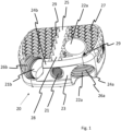
- Fig.1 shows a Cage 20 in a perspective view.
- the Cage 20 is designed as a cervical disc replacement.
- this can have a height of 3 to 10 mm (maximum height).
- the top side 25 and the bottom side do not run parallel to each other, but rather at an angle to each other. These form a so-called lordosis angle.
- the lordosis angle can be between 2 and 8°, for example.
- the Cage 20 is made of a printed titanium alloy (e.g. manufactured using SLM).
- the top side 25 and bottom side of the cage 20 are provided with a grid structure 27, at least in sections.
- the top side 25 and bottom side are thus permeable for bone replacement material. There is a cavity in between.
- a web 28 extends approximately centrally over the cage 20.
- a web 28 extends both on the top side 25 and on the bottom side, which serves for reinforcement.
- the cage can further comprise spikes 29 on its upper side 25 and/or lower side, which press into the bone substance and thus improve the fixation of the cage 20.
- the side wall 23 of the cage 20 includes a thread as a holder 21 for an application tool. This allows an application tool (see Fig.8 ) into the Cage 20 and the cage can be placed.
- the passages 22a, 22b each comprise a thread 26a, 26b, in which either the head of the locking screw is anchored or in which a cap (see Fig.3 ) is used.
- the passage 22a leads to the top side 25 and the passage 22b to the bottom side.
- Fig.2 shows a locking screw 30.
- the locking screw 30 comprises a head with a head thread 31.
- a shaft extends from the head thread 31 and comprises a thread 32 that can be screwed into the bone substance.
- the locking screw 30 can comprise a self-tapping tip 33.
- the cap is frustoconical in shape and has a conical external thread 11.
- the underside 12 of the cap 10 is closed.
- the external thread 11 preferably corresponds to the head thread of the locking screw (31 in Fig.2 ).
- the cap can have a diameter d (maximum diameter) of 3 to 8 mm, preferably 4 to 6 mm.
- the length l of the cap 10 can be 3 to 10 mm.
- the cone angle ⁇ is preferably 15 to 30°.
- Fig.4 is a perspective view of the cage into which a cap 10 is now to be inserted.
- the cap 10 is screwed into the thread 26b of the bushing 22b.
- the cap 10 is designed as a grub screw and therefore has a drive 13 which extends as a blind hole through the thread of the cap 10.
- the drive 13 can, for example, be designed as an internal multi-tooth.
- the cap 13 is preferably made of a solid metal material, in particular titanium or a titanium alloy.
- Fig.5 is a longitudinal section through the middle of the Cage 10.
- the receptacle 21 leads into the cage. Bone replacement material can be injected into the cavity between the top and bottom via the receptacle 21.
- Fig.6 is a longitudinal section of the cage in the area of a passage 22b.
- the passage 22b with the thread 26b can, as provided in a further embodiment, comprise lateral openings 19 through which bone replacement material can enter the cage 20.
- the openings 19 are shown schematically in this view.
- the thread 26b is conical. Due to the inclination of the passage 22b, the thread can only extend over a portion of the passage 22b. Preferably, the thread 26b extends from the top of the cage to its bottom.
- Fig.7 shows how a cap 10 is now screwed into a bushing 26a.
- the cap 10 comprises an outer, proximal edge 15 which is approximately flush with the side wall of the cage 20.
- the inner, distal edge 14 is approximately flush with the top or bottom of the cage 20.
- Fig.8 is a perspective view of an application tool 40.
- the application tool 40 comprises a handle 41 which comprises a rod 42, at the end of which a thread is arranged onto which the cage 20 can be screwed.
- the application tool 40 comprises a rod 42 on each side of the handle 41, to which a cage 20 can be attached.
- the application tool 40 may further comprise a spacer 43.
- the spacer 43 can optionally be inserted into the rod 42, in particular locked into place.
- the spacer 43 prevents the cage 20 from being inserted too deeply between the vertebrae by coming into contact with the adjacent vertebral body.
- Fig.9 shows a schematic representation of a cement applicator 50.
- the cement applicator 50 comprises a handle 51, via which bone replacement material can be squeezed out, for example by pressing or turning.
- the bone replacement material exits the cement applicator 50 via the channel 52, which is designed, for example, as a tube.
- the channel 52 comprises a thread 53 at its distal end.
- This thread 53 can, for example, be screwed into the cage receptacle after the application tool has been unscrewed.
- the thread 53 can correspond to the external thread of the cap, whereby the passages can thus be used for applying bone replacement material.
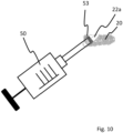
- Fig.10 illustrates how bone replacement material is introduced through a passage 22a of the cage 20 by means of the cement applicator 50.
- the cement applicator 50 is screwed into the passage 22a with the thread 53.
- bone replacement material can be introduced, which is initially distributed primarily above or below the adjacent vertebra.
- height differences between the vertebra and the cage can be equalized in this way. This results in a more even distribution of pressure.
- Fig. 11 shows schematically a spike 16 which is provided instead of the cap according to a further aspect of the invention.
- the spike 60 comprises a head thread 61, which can be designed in particular according to the cap described above.
- the head end of the spike 60 is bordered by a point 62, which is at the end of the shaft.
- the shaft may be provided with barbs 63.
- the spikes 60 can be screwed in with the head thread and anchor themselves in the cage 20.
- the tip 62 of the respective spike 60 presses into the bone tissue and anchors the cage 20.
- Anchoring is quicker than with an anchoring screw. It is also possible to pre-mount the spikes 60 in the cage 20 so that the tip 62 does not protrude when the cage 20 is inserted.
- the invention made it possible to provide a cage that can be used flexibly.
Landscapes
- Health & Medical Sciences (AREA)
- Orthopedic Medicine & Surgery (AREA)
- Cardiology (AREA)
- Oral & Maxillofacial Surgery (AREA)
- Transplantation (AREA)
- Engineering & Computer Science (AREA)
- Biomedical Technology (AREA)
- Heart & Thoracic Surgery (AREA)
- Vascular Medicine (AREA)
- Life Sciences & Earth Sciences (AREA)
- Animal Behavior & Ethology (AREA)
- General Health & Medical Sciences (AREA)
- Public Health (AREA)
- Veterinary Medicine (AREA)
- Prostheses (AREA)
Abstract
Description
- Die Erfindung betrifft einen Cage, welcher als Bandscheibenersatz für die Wirbelsäule ausgebildet ist. Insbesondere betrifft die Erfindung einen zervikalen Cage.
- Zur operativen Wirbelsäulenstabilisierung sind sogenannte Cages bekannt. Diese dienen der Versteifung zweier benachbarter Wirbelkörper und werden anstelle der Bandscheibe zwischen den Wirbeln eingesetzt.
- Ein derartiger Cage ist üblicherweise aus Metall, insbesondere Titan, oder aus einem Kunststoff, wie beispielsweise PEEK, ausgebildet. Zur Verbesserung der Fixierung ist es bekannt, Verankerungsschrauben für eine kraniale und kaudale Befestigung quer durch den Cage in die Wirbelkörper zu schrauben.
- Weiter kann der Cage innen hohl ausgebildet sein, so dass dieser mit einem Knochenersatzmaterial befüllt werden kann. Bei dem Knochenersatzmaterial handelt es sich zumeist um ein Kalziumphosphatmaterial, in welches natürliches Knochengewebe einwachsen kann.
- Der Erfindung liegt gegenüber vorstehend genanntem Hintergrund die Aufgabe zugrunde, einen Cage bereitzustellen, welcher flexibel verwendet werden kann. Insbesondere ist es eine Aufgabe der Erfindung, einen verbesserten Cage bereitzustellen, welcher wahlweise mit oder ohne Verankerungsschrauben implantiert werden kann.
- Die Aufgabe der Erfindung wird bereits durch einen Cage mit einer Kappe nach Anspruch 1 gelöst.
- Bevorzugte Ausführungsformen und Weiterbildungen der Erfindung sind dem Gegenstand der abhängigen Ansprüche, der Beschreibung sowie den Zeichnungen zu entnehmen.
- Die Erfindung betrifft einen Cage, welcher als Bandscheibenersatz für die Wirbelsäule ausgebildet ist. Insbesondere betrifft die Erfindung einen Cage, welcher für einen zervikalen Bandscheibenersatz ausgebildet ist.
- Der Cage umfasst zumindest eine Aufnahme zum Anbringen eines Applikationswerkzeuges.
- Die Aufnahme kann insbesondere als Gewinde ausgebildet sein, über das der Cage mit dem Applikationswerkzeug verbunden werden kann. Das Gewinde kann insbesondere an einer Seitenwand, vorzugsweise an einer anterioren Seitenwand des Cages angeordnet sein.
- Über die Aufnahme wird der Cage sicher gehalten und kann vom Operateur nach einer Resektion der Bandscheibe zwischen den Wirbeln eingesetzt werden.
- Weiter umfasst der Cage zwei Durchführungen für jeweils eine Verankerungsschraube. Die beiden Durchführungen verlaufen insbesondere schräg von unten nach oben bzw. oben nach unten durch den Cage und dienen so einer kaudalen und kranialen Verankerung.
- Die Durchführungen können ein Gewinde umfassen. So können die Durchführungen insbesondere im Zusammenwirken mit Verankerungsschrauben verwendet werden, welche ein Kopfgewinde aufweisen und so am Ende des Einschraubvorgangs winkelstabil mit dem Cage verbunden sind.
- Gemäß der Erfindung gehört zu dem Cage eine Kappe, mittels welcher die Durchführungen für die Verankerungsschrauben verschließbar sind.
- Die Kappen können dann verwendet werden, wenn vom Operateur keine Verankerungsschrauben verwendet werden. So ist der Cage flexibler verwendbar.
- Das Verschließen der Durchführungen für die Verankerungsschrauben verbessert des Weiteren das Einbringen von Knochenersatzmaterial in den Cage.
- Durch die Kappen wird verhindert, dass Knochenersatzmaterial lateral aus dem Cage austritt.
- Als Anschluss zum Injizieren von Knochenersatzmaterial kann beispielsweise die Aufnahme für das Handhabungswerkzeug dienen. Diese kann insbesondere als Gewinde ausgebildet sein, welches sich in das zumindest teilweise hohle Innere des Cage erstreckt.
- Durch die Kappen wird ein laterales Austreten des Knochenersatzmaterials blockiert.
- Weiter können auch die Durchführungen für die Verankerungsschrauben zum Injizieren von Knochenersatzmaterial verwendet werden. Dabei kann beispielsweise eine Durchführung mittels einer Kappe verschlossen werden und über die andere Durchführung das Knochenersatzmaterial injiziert werden. Über die Durchführungen kann insbesondere gezielt Knochenersatzmaterial oberhalb oder unterhalb des Cage eingebracht werden. Die Kappe kann insbesondere als Gewindekappe ausgebildet sein. Vorzugsweise ist die Kappe als Madenschraube ausgebildet. Bei einer derartigen Madenschraube erstreckt sich der Antrieb der Schraube als Sackloch durch das Gewinde.
- Die Kappe steht vorzugsweise im eingesetzten Zustand weder kranial noch kaudal aus dem Cage.
- Vorzugsweise umfasst die Kappe ein konisches Gewinde. Ein derartiges konisches Gewinde hat den Vorteil, dass die Gewindezüge auf kurzem Weg miteinander in Eingriff kommen. Der Einschraubvorgang erfolgt somit schnell und mit wenig Umdrehungen.
- Insbesondere können Cage und Kappe derart ausgebildet sein, dass sich die Kappe mit weniger als zwei Umdrehungen, insbesondere mit 0,3 bis 0,5 Umdrehungen vollständig einschrauben lässt.
- Das Gewinde kann insbesondere als einzügiges Gewinde ausgebildet sein.
- Die Kappe kann insbesondere kegelstumpfförmig ausgebildet sein. Insbesondere kann der Kegelwinkel α zwischen 50 und 30° liegen.
- Die Kappe ist vorzugsweise derart ausgebildet, dass sie sich im eingesetzten Zustand durch die Durchführung erstreckt, aber nicht aus der Durchführung herausschaut.
- Es ist insbesondere vorgesehen, dass die Kappe im eingesetzten Zustand eine innere Kante umfasst, welche mit der Unterseite oder Oberseite des Cage fluchtet. Bei der inneren Kante im Sinne der Erfindung handelt es sich insbesondere um den distalen Rand der Kappe, also insbesondere um den distalen Rand der Madenschraube.
- Diese Kante liegt im eingesetzten Zustand in etwa auf Höhe der Oberseite bzw. Unterseite des Cage.
- Eine äußere Kante dagegen fluchtet vorzugsweise mit der Seitenwand des Cage. Bei der äußeren Kante handelt es sich insbesondere um den proximalen Rand der Kappe.
- Bei dieser Ausführungsform erstreckt sich somit die eingesetzte Kappe über eine maximal mögliche Länge. Des Weiteren kann eine Kappe mit verhältnismäßig großem Durchmesser bereitgestellt werden, was es wiederum ermöglicht, Durchführungen für verhältnismäßig große Verriegelungsschrauben bereitzustellen.
- Die Durchführungen können sich insbesondere in einem Winkel kranial und/oder kaudal von 30 bis 45° durch den Cage, bezogen auf dessen Mittelebene, erstrecken.
- Weiter können sich die Durchführungen lateral in einem Winkel von 5 bis 15° zu einer Mittelachse des Cages erstrecken.
- Bei einer Ausführungsform der Erfindung ist der Cage aus gedrucktem Titan oder einer Titanlegierung ausgebildet. Der Cage kann insbesondere als Käfig ausgebildet sein. Dabei kann sich ein Gitter zumindest abschnittweise über die Oberseite oder Unterseite erstrecken. Das Gitter kann von Knochenersatzmaterial durchdrungen werden. Das Gitter kann insbesondere die Form eines Gewebes aufweisen, also Schlaufen umfassen, welche ineinander greifen oder sich umschlingen. Diese Schlaufen sind aber nicht aus Stoff, sondern aus gedrucktem Titan bzw. einer gedruckten Titanlegierung ausgebildet.
- Gemäß einem weiteren Aspekt der Offenbarung bezieht sich diese auf einen Cage, welcher als Bandscheibenersatz für die Wirbelsäule ausgebildet ist.
- Insbesondere bezieht sich die Offenbarung auf den vorstehend beschriebenen Cage. Der Cage weist zwei Durchführungen auf, die insbesondere zum Durchführen von Verankerungsschrauben dienen können.
- Gemäß diesem Aspekt ist an Stelle einer Kappe ein Spike vorgesehen, welcher in zumindest einer Durchführung, vorzugsweise in beiden Durchführungen sitzt.
- Der Spike umfasst einen Schaft mit einer Spitze. Der Schaft weist aber kein Gewinde auf. Vielmehr kann der Schaft Widerhaken umfassen, die im Knochengewebe den Spike verankern.
- Vorzugsweise umfasst der Spike ein Kopfgewinde, welches in das Gewinde der Durchführung eingeschraubt wird. Das Gewinde kann, wie vorstehend beschrieben, insbesondere konisch ausgebildet sein.
- Insbesondere kann der Kopf des Spike wie die vorstehend beschriebene Kappe ausgebildet sein.
- Über das Kopfgewinde kann der Spike wesentlich schneller und einfacher als eine Schraube in das angrenzende Knochengewebe geführt und so verankert werden.
- Der oder die Spikes können insbesondere vormontiert im Cage sitzen. Es ist insbesondere vorgesehen, dass in dem vormontierten Zustand die Spitze des Spikes nicht aus der Oberseite bzw. Unterseite des Cage herausschaut. Erst mit dem Eindrehen des Kopfgewindes wird die Spitze in den Knochen geführt und verankert so den Cage.
- Die Erfindung betrifft des Weiteren ein Set mit einem Cage nebst Kappe und/oder Cage, wie es vorstehend beschrieben wurde. Das Set umfasst des Weiteren eine Verankerungsschraube.
- Die Schraube kann insbesondere ein Gewinde mit einem Schaft aufweisen, welches dazu ausgebildet ist, in den angrenzenden Wirbelkörper gedreht zu werden.
- Weiter umfasst die Verankerungsschraube vorzugsweise einen Kopf mit einem Kopfgewinde. Das Kopfgewinde kann insbesondere dem Gewinde der Kappe entsprechen.
- Die Verankerungsschraube wird anstelle der Kappe verwendet, soweit der Operateur den Cage kaudal und kranial verankern möchte.
- Das Set kann des Weiteren ein Applikationswerkzeug mit einem Griff umfassen, welches an der Aufnahme befestigbar ist.
- Es kann sich insbesondere um ein Applikationswerkzeug handeln, bei welchem der Griff eine Stange mit einem Gewinde an der Spitze umfasst. An dem Gewinde kann der Cage angebracht werden, um diesen einzubringen.
- Weiter kann das Set einen Zementapplikator umfassen, welcher mit einer der Durchführungen und/oder der Aufnahme verbindbar ist, um Knochenersatzmaterial in den Cage zu applizieren.
- Es ist insbesondere vorgesehen, dass nach dem Einsetzen des Cages mittels des Applikationswerkzeugs die Aufnahme das einem Kanal, insbesondere einem Schlauch verbunden wird, über den Knochenersatzmaterial in das Innere des Cages appliziert wird.
- Bei der Verwendung von Kappen sichern diese, dass das Knochenersatzmaterial nicht an der Seitenwand des Cages austritt.
- Weiter kann auch die Durchführung selbst zum Applizieren von Knochenersatzmaterial verwendet werden.
- Insbesondere kann die Durchführung seitliche Öffnungen umfassen, so dass Knochenersatzmaterial aus der Durchführung in den Cage eintreten kann. Weiter kann das Knochenersatzmaterial über die Durchführung auch oberhalb und unterhalb unter dem Cage fließen, wo er aufgrund der gitterartigen Struktur der Oberseite und Unterseite in den Cage eindringt.
- Der Gegenstand der Erfindung soll im Folgenden bezugnehmend auf ein Ausführungsbeispiel anhand der Zeichnungen
Fig. 1 bis Fig. 12 näher erläutert werden. -
Fig. 1 ist eine perspektivische Ansicht eines Cages ohne eingesetzte Kappen. -
Fig. 2 zeigt eine Verankerungsschraube. -
Fig. 3 zeigt eine Kappe. -
Fig. 4 ist eine perspektivische Ansicht von Cage und Kappe. -
Fig. 5 ist ein mittiger Längsschnitt des Cage. -
Fig. 6 ist ein Längsschnitt durch eine Durchführung. -
Fig. 7 ist ein Längsschnitt, wobei nunmehr die Kappe eingesetzt ist. -
Fig. 8 ist eine perspektivische Ansicht eines Applikationswerkzeugs. -
Fig. 9 ist eine schematische Darstellung eines Zementapplikators, wie er Bestandteil eines erfindungsgemäßen Sets sein kann. -
Fig. 10 illustriert, wie über eine Durchführung des Cage Knochenersatzmaterial eingebracht wird. -
Fig. 11 zeigt einen Spike. -
Fig. 12 ist eine Schnittansicht des Cages nebst eingesetzten Spikes. -
Fig. 1 zeigt in einer perspektivischen Ansicht einen Cage 20. - Der Cage 20 ist als zervikaler Bandscheibenersatz ausgebildet.
- Dieser kann insbesondere eine Höhe von 3 bis 10 mm aufweisen (maximale Höhe).
- Oberseite 25 und Unterseite verlaufen gemäß einer bevorzugten Ausführungsform nicht parallel, sondern schräg zueinander. Diese bilden einen sogenannten Lordosewinkel. Der Lordosewinkel kann beispielsweise zwischen 2 und 8° liegen.
- Der Cage 20 ist aus einer gedruckten Titanlegierung ausgebildet (z.B. mittels SLM hergestellt).
- Oberseite 25 und Unterseite des Cages 20 sind zumindest abschnittsweise mit einer Gitterstruktur 27 versehen. So sind Oberseite 25 und Unterseite für Knochenersatzmaterial durchlässig. Dazwischen befindet sich ein Hohlraum.
- Weiter erstreckt sich ein Steg 28 in etwa mittig über den Cage 20. Es erstreckt sich sowohl auf der Oberseite 25 als auch auf der Unterseite ein Steg 28, welcher der Verstärkung dient.
- Der Cage kann an seiner Oberseite 25 und/oder Unterseite des Weiteren Spitzen 29 umfassen, welche sich in die Knochensubstanz eindrücken und so die Fixierung des Cages 20 verbessern.
- Als Aufnahme 21 für ein Applikationswerkzeug umfasst die Seitenwand 23 des Cage 20 ein Gewinde. So kann ein Applikationswerkzeug (siehe
Fig. 8 ) in den Cage 20 geschraubt werden und der Cage kann platziert werden. - Zur kranialen und kaudalen Verankerung mittels einer Verankerungsschraube (30 in
Fig. 2 ) umfasst der Cage 20 Durchführungen 22a, 22b, welche von der Seitenwand ausgehend schräg durch den Cage 20 verlaufen. - Die Durchführungen 22a, 22b umfassen jeweils ein Gewinde 26a, 26b, in welchem sich entweder der Kopf der Verriegelungsschraube verankert oder in welches eine Kappe (siehe
Fig. 3 ) eingesetzt wird. - Die Durchführung 22a führt zur Oberseite 25 und die Durchführung 22b zur Unterseite.
-
Fig. 2 zeigt eine Verriegelungsschraube 30. - Die Verriegelungsschraube 30 umfasst einen Kopf mit einem Kopfgewinde 31.
- Ausgehend vom Kopfgewinde 31 erstreckt sich ein Schaft, welcher ein Gewinde 32 umfasst, das in die Knochensubstanz gedreht werden kann. Die Verriegelungsschraube 30 kann eine selbstschneidende Spitze 33 umfassen.
- Statt einer Verriegelungsschraube 30, wie in
Fig. 2 dargestellt, kann die inFig. 3 dargestellte Kappe 10 verwendet werden. - Die Kappe ist kegelstumpfförmig ausgebildet und umfasst ein konisches Außengewinde 11. Die Unterseite 12 der Kappe 10 ist verschlossen.
- Das Außengewinde 11 entspricht vorzugsweise dem Kopfgewinde der Verriegelungsschraube (31 in
Fig. 2 ). - Die Kappe kann einen Durchmesser d (maximaler Durchmesser) von 3 bis 8 mm, vorzugsweise 4 bis 6 mm aufweisen. Die Länge l der Kappe 10 kann 3 bis 10 mm betragen.
- Der Kegelwinkel α beträgt vorzugsweise 15 bis 30°.
-
Fig. 4 ist eine perspektivische Ansicht des Cages, in den nunmehr eine Kappe 10 eingesetzt werden soll. - Die Kappe 10 wird in das Gewinde 26b der Durchführung 22b geschraubt.
- Die Kappe 10 ist als Madenschraube ausgebildet und hat mithin einen Antrieb 13, welcher sich als Sackloch durch das Gewinde der Kappe 10 erstreckt. Der Antrieb 13 kann beispielsweise als Innenvielzahn ausgebildet sein.
- Die Kappe 13 ist vorzugsweise aus einem Vollmaterial aus Metall, insbesondere aus Titan oder einer Titanlegierung, ausgebildet.
-
Fig. 5 ist ein Längsschnitt mittig durch den Cage 10. - Zu erkennen ist, dass die Aufnahme 21 in den Cage hineinführt. Über die Aufnahme 21 kann so Knochenersatzmaterial in den Hohlraum zwischen Oberseite und Unterseite injiziert werden.
-
Fig. 6 ist ein Längsschnitt des Cages im Bereich einer Durchführung 22b. - Die Durchführung 22b mit dem Gewinde 26b kann, wie es bei einer weiteren Ausführungsform vorgesehen ist, seitliche Öffnungen 19 umfassen, über die Knochenersatzmaterial in den Cage 20 hineintreten kann. Die Öffnungen 19 sind in dieser Ansicht schematisch dargestellt.
- Das Gewinde 26b ist konisch ausgebildet. Aufgrund der Schrägstellung der Durchführung 22b kann sich das Gewinde nur über einen Teilbereich der Durchführung 22b erstrecken. Vorzugsweise erstreckt sich das Gewinde 26b von der Oberseite des Cage bis zu dessen Unterseite.
-
Fig. 7 zeigt, wie nunmehr eine Kappe 10 in eine Durchführung 26a eingeschraubt ist. - Die Kappe 10 umfasst eine äußere, proximale Kante 15, welche in etwa mit der Seitenwand des Cages 20 fluchtet.
- Die innere, distale Kante 14 fluchtet in etwa mit der Ober- oder Unterseite des Cages 20.
-
Fig. 8 ist eine perspektivische Ansicht eines Applikationswerkzeugs 40. Das Applikationswerkzeug 40 umfasst einen Griff 41, der eine Stange 42 umfasst, an deren Ende ein Gewinde angeordnet ist, auf das der Cage 20 geschraubt werden kann. - In diesem Ausführungsbeispiel umfasst das Applikationswerkzeug 40 beidseitig des Griffes 41 jeweils eine Stange 42, an der ein Cage 20 angebracht werden kann.
- Das Applikationswerkzeug 40 kann des Weiteren einen Abstandshalter 43 umfassen.
- Der Abstandshalter 43 kann optional in die Stange 42 eingesetzt, insbesondere verrastet werden. Der Abstandshalter 43 verhindert, dass der Cage 20 zu tief zwischen die Wirbel eingeführt wird, indem dieser am angrenzenden Wirbelkörper zur Anlage kommt.
-
Fig. 9 zeigt in einer schematischen Darstellung einen Zementapplikator 50. - Der Zementapplikator 50 umfasst einen Griff 51, über den, beispielsweise durch Drücken oder Drehen, Knochenersatzmaterial ausgepresst werden kann.
- Das Knochenersatzmaterial tritt über den Kanal 52, welcher beispielsweise als Schlauch ausgebildet ist, aus dem Zementapplikator 50 heraus.
- Der Kanal 52 umfasst an seinem distalen Ende ein Gewinde 53.
- Dieses Gewinde 53 kann beispielsweise in die Aufnahme des Cages eingedreht werden, nachdem das Applikationswerkezeug herausgedreht wurde.
- Gemäß einer weiteren Ausführungsform kann das Gewinde 53 dem Außengewinde der Kappe entsprechen, wobei so die Durchführungen zum Applizieren von Knochenersatzmaterial verwendet werden können.
-
Fig. 10 illustriert, wie mittels des Zementapplikators 50 Knochenersatzmaterial durch eine Durchführung 22a des Cage 20 eingebracht wird. - Der Zementapplikator 50 ist mit dem Gewinde 53 in die Durchführung 22a geschraubt.
- Auf diese Weise kann Knochenersatzmaterial eingebracht werden, welches sich vorwiegend zunächst oberhalb oder unterhalb des angrenzenden Wirbels verteilt. So können insbesondere Höhenunterschiede zwischen Wirbel und Cage egalisiert werden. Es kommt zu einer gleichmäßigeren Druckverteilung.
-
Fig. 11 zeigt schematisch einen Spike 16, welcher gemäß einem weiteren Aspekt der Erfindung anstelle der Kappe vorgesehen ist. - Der Spike 60 umfasst ein Kopfgewinde 61, welches insbesondere entsprechend vorstehend beschriebener Kappe ausgebildet sein kann.
- An das Kopfende grenzt bei dem Spike 60 allerdings eine Spitze 62 an, welche am Ende des Schaftes ist.
- Der Schaft kann mit Widerhaken 63 versehen sein.
- Wie in
Fig. 12 dargestellt, können die Spikes 60 mit dem Kopfgewinde eingedreht werden und verankern sich im Cage 20. - Die Spitze 62 des jeweiligen Spikes 60 drückt sich so ins Knochengewebe und verankert den Cage 20.
- Gegenüber einer Verankerungsschraube geht die Verankerung schneller vonstatten. Auch ist denkbar, die Spikes 60 bereits im Cage 20 vorzumontieren, dass die Spitze 62 noch nicht herausschaut, wenn der Cage 20 eingesetzt wird.
- Durch die Erfindung konnte ein flexibel verwendbarer Cage bereitgestellt werden.
-
- 10
- Kappe
- 11
- Außengewinde
- 12
- Unterseite
- 13
- Antrieb
- 14
- innere Kante
- 15
- äußere Kante
- 19
- Öffnung
- 20
- Cage
- 21
- Aufnahme
- 22a, 22b
- Durchführung
- 23
- Seitenwand
- 24a, 24b
- Ecke
- 25
- Oberseite
- 26a, 26b
- Gewinde
- 27
- Gitterstruktur
- 28
- Steg
- 29
- Spitze
- 30
- Verankerungsschraube
- 31
- Kopfgewinde
- 32
- Gewinde
- 33
- selbstschneidende Spitze
- 40
- Applikationswerkzeug
- 41
- Griff
- 42
- Stange
- 43
- Abstandshalter
- 50
- Zementapplikator
- 51
- Griff
- 52
- Kanal
- 53
- Gewinde
- 60
- Spike
- 61
- Kopfgewinde
- 62
- Spitze
- 63
- Widerhaken
Claims (14)
- Cage (20), welcher als Bandscheibenersatz für die Wirbelsäule ausgebildet ist, insbesondere als zervikaler Bandscheibenersatz,wobei der Cage (20) zumindest eine Aufnahme (21) zum Anbringen eines Applikationswerkzeugs (40) umfasst,und wobei der Cage (20) zumindest zwei Durchführungen (22a, 22b) für jeweils eine Verankerungsschraube (30) umfasst,wobei eine Kappe (10) vorgesehen ist, mittels welcher die Durchführungen (22a, 22b) für die Verankerungsschrauben (30) verschließbar sind.
- Cage (20) nach dem vorstehenden Anspruch, dadurch gekennzeichnet, dass die Kappe (10) als Gewindekappe ausgebildet ist, welche in ein Gewinde (26a, 26b) der Durchführung (22a, 22b) geschraubt ist.
- Cage (20) nach dem vorstehenden Anspruch, dadurch gekennzeichnet, dass die Kappe (10) ein konisches Gewinde (32) umfasst.
- Cage (20) nach einem der vorstehenden Ansprüche, dadurch gekennzeichnet, dass die Kappe (10) kegelstumpfförmig ausgebildet ist, insbesondere mit einem Kegelwinkel α von 15 bis 30°.
- Cage (20) nach einem der vorstehenden Ansprüche, dadurch gekennzeichnet, dass bei einer eingesetzten Kappe (10) diese eine innere Kante (14) umfasst, welche mit der Unterseite (12) oder Oberseite (25) des Cage (20) fluchtet, wobei eine äußere Kante (15) mit der Seitenwand des Cage (20) fluchtet.
- Cage (20) nach einem der vorstehenden Ansprüche, dadurch gekennzeichnet, dass die Durchführungen (22a, 22b) sich schräg durch den Cage (20) erstrecken.
- Cage nach dem vorstehenden Anspruch, dadurch gekennzeichnet, dass die Durchführungen (22a, 22b) sich schräg in einem Winkel kranial und/oder kaudal von 30 bis 45° durch den Cage (20) erstrecken.
- Cage (20) nach einem der vorstehenden Ansprüche,
dadurch gekennzeichnet, dass die Durchführungen (22a, 22b) lateral in einem Winkel von 5 bis 15° zur Mittelachse angeordnet sind. - Cage (20) nach einem der vorstehenden Ansprüche, dadurch gekennzeichnet, dass der Cage (20) als Käfig aus gedrucktem Titan oder einer Titanlegierung ausgebildet ist.
- Cage (20), welcher als Bandscheibenersatz für die Wirbelsäule ausgebildet ist, insbesondere als zervikaler Bandscheibenersatz,wobei der Cage (20) zumindest eine Aufnahme (21) zum Anbringen eines Applikationswerkzeugs umfasst,und wobei der Cage (20) zumindest zwei Durchführungen umfasst,dadurch gekennzeichnet, dass in zumindest einer Durchführung (22a, 22b) ein Spike (60) mit einem Kopfgewinde (61) vorgesehen ist, mittels dessen der Cage (20) kranial und/oder kaudal verankerbar ist.
- Cage nach dem vorstehenden Anspruch, dadurch gekennzeichnet, dass der Spike vormontiert ist.
- Set mit einem Cage (20) nebst Kappe (10) nach einem der vorstehenden Ansprüche, weiter umfassend zumindest eine Verankerungsschraube (30).
- Set nach dem vorstehenden Anspruch, weiter umfassend ein Applikationswerkzeug mit einem Griff, welches an der Aufnahme befestigbar ist.
- Set nach einem der vorstehenden Ansprüche, weiter umfassend einen Zementapplikator (50), der mit einer der Durchführungen (22a, 22b) und/oder der Aufnahme verbindbar ist, um Knochenersatzmaterial in den Cage (20) zu applizieren.
Applications Claiming Priority (1)
| Application Number | Priority Date | Filing Date | Title |
|---|---|---|---|
| DE102023102881.2A DE102023102881B4 (de) | 2023-02-07 | 2023-02-07 | Zervikaler Cage |
Publications (2)
| Publication Number | Publication Date |
|---|---|
| EP4413957A1 true EP4413957A1 (de) | 2024-08-14 |
| EP4413957B1 EP4413957B1 (de) | 2026-04-01 |
Family
ID=89843690
Family Applications (1)
| Application Number | Title | Priority Date | Filing Date |
|---|---|---|---|
| EP24155681.0A Active EP4413957B1 (de) | 2023-02-07 | 2024-02-05 | Zervikaler cage |
Country Status (2)
| Country | Link |
|---|---|
| EP (1) | EP4413957B1 (de) |
| DE (1) | DE102023102881B4 (de) |
Families Citing this family (1)
| Publication number | Priority date | Publication date | Assignee | Title |
|---|---|---|---|---|
| WO2026024874A1 (en) | 2024-07-23 | 2026-01-29 | Futurespine Inc. | Intervertebral members and methods of using a bone reinforcing composition for retaining the intervertebral members |
Citations (3)
| Publication number | Priority date | Publication date | Assignee | Title |
|---|---|---|---|---|
| US20110022173A1 (en) * | 2009-07-24 | 2011-01-27 | Warsaw Orthopedic, Inc. | Implant with an interference fit fastener |
| US20120232599A1 (en) * | 2011-03-10 | 2012-09-13 | Jared Schoenly | Awl screw fixation members and related systems |
| US20210401587A1 (en) * | 2019-04-30 | 2021-12-30 | Life Spine, Inc. | Spine implant with cam screws for inhibiting bone anchor backout |
Family Cites Families (3)
| Publication number | Priority date | Publication date | Assignee | Title |
|---|---|---|---|---|
| US6849093B2 (en) | 2001-03-09 | 2005-02-01 | Gary K. Michelson | Expansion constraining member adapted for use with an expandable interbody spinal fusion implant and method for use thereof |
| US20080249569A1 (en) | 2007-04-03 | 2008-10-09 | Warsaw Orthopedic, Inc. | Implant Face Plates |
| US10849758B2 (en) * | 2018-08-22 | 2020-12-01 | Institute for Musculoskeletal Science and Education, Ltd. | Spinal fusion implant |
-
2023
- 2023-02-07 DE DE102023102881.2A patent/DE102023102881B4/de active Active
-
2024
- 2024-02-05 EP EP24155681.0A patent/EP4413957B1/de active Active
Patent Citations (3)
| Publication number | Priority date | Publication date | Assignee | Title |
|---|---|---|---|---|
| US20110022173A1 (en) * | 2009-07-24 | 2011-01-27 | Warsaw Orthopedic, Inc. | Implant with an interference fit fastener |
| US20120232599A1 (en) * | 2011-03-10 | 2012-09-13 | Jared Schoenly | Awl screw fixation members and related systems |
| US20210401587A1 (en) * | 2019-04-30 | 2021-12-30 | Life Spine, Inc. | Spine implant with cam screws for inhibiting bone anchor backout |
Also Published As
| Publication number | Publication date |
|---|---|
| DE102023102881A1 (de) | 2024-08-08 |
| EP4413957B1 (de) | 2026-04-01 |
| DE102023102881B4 (de) | 2025-01-30 |
Similar Documents
| Publication | Publication Date | Title |
|---|---|---|
| EP1589909B1 (de) | Zwischenwirbelimplantat | |
| DE69730360T2 (de) | Expandierbarer osteosynthesekäfig | |
| EP1001722B1 (de) | Spreizbares zwischenwirbelimplantat | |
| DE69616823T2 (de) | Zwischenwirbelimplantat als wirbelkäfig ausgebildet | |
| EP0770367B1 (de) | Zwischenwirbelimplantat | |
| DE10260222B4 (de) | Rohrförmiges Element für ein in der Wirbelsäulen- oder der Knochenchirurgie zu verwendendes Implantat und Implantat mit einem solchen Element | |
| DE102012023042B3 (de) | Expandierbarer Cage zur interkorporellen Fusion von Lendenwirbeln | |
| DE69624672T2 (de) | Wirbelsäulenimplantat | |
| EP0923355B1 (de) | Implantat zum fusionieren von zwei benachbarten wirbeln der wirbelsäule | |
| DE19831336A1 (de) | Knochenschraube, insbesondere für den Einsatz bei translaminärer Wirbelverschraubung | |
| EP1572040A2 (de) | Implantat zum einsatz bei versteifungsoperationen an der wirbelsäule | |
| WO2005004756A2 (de) | Bandscheibenprothese | |
| EP1476098A1 (de) | Zwischenwirbelimplantat | |
| CH674705A5 (de) | ||
| EP2829242A1 (de) | System zur Verankerung einer Pedikelschraube, zugehöriger Bausatz, Spacer und Pedikelaugmentat | |
| WO2005020859A1 (de) | Implantat zum verschluss einer öffnung des annulus fibrosus | |
| EP1713421A1 (de) | Zwischenwirbelimplantat sowie chirurgisches verfahren zur spondylodese der lendenwirbelsäule | |
| EP3331472B1 (de) | Implantat zum verschliessen eines defekts im anulus fibrosus einer bandscheibe | |
| EP4413957B1 (de) | Zervikaler cage | |
| DE102015101675B4 (de) | Implantat | |
| DE202008016697U1 (de) | Implantatschraube | |
| DE19720241B4 (de) | Wirbelkörperfusionsimplantat | |
| EP1674053A1 (de) | Implantat zum Ersetzen von Knochen oder Knorpel, mit Fixierglied | |
| DE202009012270U1 (de) | Knochenplattenverschraubung | |
| DE102012024688A1 (de) | Marknagel, insbesondere verriegelbarer Marknagel, mit Führungsdrahtdurchlässen |
Legal Events
| Date | Code | Title | Description |
|---|---|---|---|
| PUAI | Public reference made under article 153(3) epc to a published international application that has entered the european phase |
Free format text: ORIGINAL CODE: 0009012 |
|
| STAA | Information on the status of an ep patent application or granted ep patent |
Free format text: STATUS: THE APPLICATION HAS BEEN PUBLISHED |
|
| AK | Designated contracting states |
Kind code of ref document: A1 Designated state(s): AL AT BE BG CH CY CZ DE DK EE ES FI FR GB GR HR HU IE IS IT LI LT LU LV MC ME MK MT NL NO PL PT RO RS SE SI SK SM TR |
|
| STAA | Information on the status of an ep patent application or granted ep patent |
Free format text: STATUS: REQUEST FOR EXAMINATION WAS MADE |
|
| 17P | Request for examination filed |
Effective date: 20241205 |
|
| GRAP | Despatch of communication of intention to grant a patent |
Free format text: ORIGINAL CODE: EPIDOSNIGR1 |
|
| STAA | Information on the status of an ep patent application or granted ep patent |
Free format text: STATUS: GRANT OF PATENT IS INTENDED |
|
| INTG | Intention to grant announced |
Effective date: 20251008 |
|
| GRAS | Grant fee paid |
Free format text: ORIGINAL CODE: EPIDOSNIGR3 |
|
| GRAA | (expected) grant |
Free format text: ORIGINAL CODE: 0009210 |
|
| STAA | Information on the status of an ep patent application or granted ep patent |
Free format text: STATUS: THE PATENT HAS BEEN GRANTED |
|
| AK | Designated contracting states |
Kind code of ref document: B1 Designated state(s): AL AT BE BG CH CY CZ DE DK EE ES FI FR GB GR HR HU IE IS IT LI LT LU LV MC ME MK MT NL NO PL PT RO RS SE SI SK SM TR |
|
| REG | Reference to a national code |
Ref country code: CH Ref legal event code: F10 Free format text: ST27 STATUS EVENT CODE: U-0-0-F10-F00 (AS PROVIDED BY THE NATIONAL OFFICE) Effective date: 20260401 Ref country code: GB Ref legal event code: FG4D Free format text: NOT ENGLISH |
|
| REG | Reference to a national code |
Ref country code: DE Ref legal event code: R096 Ref document number: 502024000951 Country of ref document: DE |
|
| REG | Reference to a national code |
Ref country code: IE Ref legal event code: FG4D Free format text: LANGUAGE OF EP DOCUMENT: GERMAN |
|
| P01 | Opt-out of the competence of the unified patent court (upc) registered |
Free format text: CASE NUMBER: UPC_APP_0010416_4413957/2026 Effective date: 20260319 |