EP4413876A2 - E-zigarettensystem und verfahren - Google Patents
E-zigarettensystem und verfahren Download PDFInfo
- Publication number
- EP4413876A2 EP4413876A2 EP24170957.5A EP24170957A EP4413876A2 EP 4413876 A2 EP4413876 A2 EP 4413876A2 EP 24170957 A EP24170957 A EP 24170957A EP 4413876 A2 EP4413876 A2 EP 4413876A2
- Authority
- EP
- European Patent Office
- Prior art keywords
- liquid
- case
- cigarette
- cartridge
- user
- Prior art date
- Legal status (The legal status is an assumption and is not a legal conclusion. Google has not performed a legal analysis and makes no representation as to the accuracy of the status listed.)
- Granted
Links
Images


Classifications
-
- A—HUMAN NECESSITIES
- A61—MEDICAL OR VETERINARY SCIENCE; HYGIENE
- A61M—DEVICES FOR INTRODUCING MEDIA INTO, OR ONTO, THE BODY; DEVICES FOR TRANSDUCING BODY MEDIA OR FOR TAKING MEDIA FROM THE BODY; DEVICES FOR PRODUCING OR ENDING SLEEP OR STUPOR
- A61M15/00—Inhalators
- A61M15/06—Inhaling appliances shaped like cigars, cigarettes or pipes
-
- A—HUMAN NECESSITIES
- A24—TOBACCO; CIGARS; CIGARETTES; SIMULATED SMOKING DEVICES; SMOKERS' REQUISITES
- A24B—MANUFACTURE OR PREPARATION OF TOBACCO FOR SMOKING OR CHEWING; TOBACCO; SNUFF
- A24B15/00—Chemical features or treatment of tobacco; Tobacco substitutes, e.g. in liquid form
- A24B15/10—Chemical features of tobacco products or tobacco substitutes
- A24B15/16—Chemical features of tobacco products or tobacco substitutes of tobacco substitutes
- A24B15/167—Chemical features of tobacco products or tobacco substitutes of tobacco substitutes in liquid or vaporisable form, e.g. liquid compositions for electronic cigarettes
-
- A—HUMAN NECESSITIES
- A24—TOBACCO; CIGARS; CIGARETTES; SIMULATED SMOKING DEVICES; SMOKERS' REQUISITES
- A24F—SMOKERS' REQUISITES; MATCH BOXES; SIMULATED SMOKING DEVICES
- A24F15/00—Receptacles or boxes specially adapted for cigars, cigarettes, simulated smoking devices or cigarettes therefor
- A24F15/01—Receptacles or boxes specially adapted for cigars, cigarettes, simulated smoking devices or cigarettes therefor specially adapted for simulated smoking devices or cigarettes therefor
- A24F15/015—Receptacles or boxes specially adapted for cigars, cigarettes, simulated smoking devices or cigarettes therefor specially adapted for simulated smoking devices or cigarettes therefor with means for refilling of liquid inhalable precursors
-
- A—HUMAN NECESSITIES
- A24—TOBACCO; CIGARS; CIGARETTES; SIMULATED SMOKING DEVICES; SMOKERS' REQUISITES
- A24F—SMOKERS' REQUISITES; MATCH BOXES; SIMULATED SMOKING DEVICES
- A24F40/00—Electrically operated smoking devices; Component parts thereof; Manufacture thereof; Maintenance or testing thereof; Charging means specially adapted therefor
- A24F40/40—Constructional details, e.g. connection of cartridges and battery parts
- A24F40/42—Cartridges or containers for inhalable precursors
-
- A—HUMAN NECESSITIES
- A24—TOBACCO; CIGARS; CIGARETTES; SIMULATED SMOKING DEVICES; SMOKERS' REQUISITES
- A24F—SMOKERS' REQUISITES; MATCH BOXES; SIMULATED SMOKING DEVICES
- A24F40/00—Electrically operated smoking devices; Component parts thereof; Manufacture thereof; Maintenance or testing thereof; Charging means specially adapted therefor
- A24F40/40—Constructional details, e.g. connection of cartridges and battery parts
- A24F40/46—Shape or structure of electric heating means
- A24F40/465—Shape or structure of electric heating means specially adapted for induction heating
-
- A—HUMAN NECESSITIES
- A24—TOBACCO; CIGARS; CIGARETTES; SIMULATED SMOKING DEVICES; SMOKERS' REQUISITES
- A24F—SMOKERS' REQUISITES; MATCH BOXES; SIMULATED SMOKING DEVICES
- A24F40/00—Electrically operated smoking devices; Component parts thereof; Manufacture thereof; Maintenance or testing thereof; Charging means specially adapted therefor
- A24F40/40—Constructional details, e.g. connection of cartridges and battery parts
- A24F40/48—Fluid transfer means, e.g. pumps
- A24F40/485—Valves; Apertures
-
- A—HUMAN NECESSITIES
- A24—TOBACCO; CIGARS; CIGARETTES; SIMULATED SMOKING DEVICES; SMOKERS' REQUISITES
- A24F—SMOKERS' REQUISITES; MATCH BOXES; SIMULATED SMOKING DEVICES
- A24F40/00—Electrically operated smoking devices; Component parts thereof; Manufacture thereof; Maintenance or testing thereof; Charging means specially adapted therefor
- A24F40/50—Control or monitoring
- A24F40/53—Monitoring, e.g. fault detection
-
- A—HUMAN NECESSITIES
- A24—TOBACCO; CIGARS; CIGARETTES; SIMULATED SMOKING DEVICES; SMOKERS' REQUISITES
- A24F—SMOKERS' REQUISITES; MATCH BOXES; SIMULATED SMOKING DEVICES
- A24F40/00—Electrically operated smoking devices; Component parts thereof; Manufacture thereof; Maintenance or testing thereof; Charging means specially adapted therefor
- A24F40/60—Devices with integrated user interfaces
-
- A—HUMAN NECESSITIES
- A24—TOBACCO; CIGARS; CIGARETTES; SIMULATED SMOKING DEVICES; SMOKERS' REQUISITES
- A24F—SMOKERS' REQUISITES; MATCH BOXES; SIMULATED SMOKING DEVICES
- A24F40/00—Electrically operated smoking devices; Component parts thereof; Manufacture thereof; Maintenance or testing thereof; Charging means specially adapted therefor
- A24F40/65—Devices with integrated communication means, e.g. wireless communication means
-
- A—HUMAN NECESSITIES
- A24—TOBACCO; CIGARS; CIGARETTES; SIMULATED SMOKING DEVICES; SMOKERS' REQUISITES
- A24F—SMOKERS' REQUISITES; MATCH BOXES; SIMULATED SMOKING DEVICES
- A24F40/00—Electrically operated smoking devices; Component parts thereof; Manufacture thereof; Maintenance or testing thereof; Charging means specially adapted therefor
- A24F40/90—Arrangements or methods specially adapted for charging batteries thereof
- A24F40/95—Arrangements or methods specially adapted for charging batteries thereof structurally associated with cases
-
- B—PERFORMING OPERATIONS; TRANSPORTING
- B65—CONVEYING; PACKING; STORING; HANDLING THIN OR FILAMENTARY MATERIAL
- B65B—MACHINES, APPARATUS OR DEVICES FOR, OR METHODS OF, PACKAGING ARTICLES OR MATERIALS; UNPACKING
- B65B3/00—Packaging plastic material, semiliquids, liquids or mixed solids and liquids, in individual containers or receptacles, e.g. bags, sacks, boxes, cartons, cans, or jars
- B65B3/04—Methods of, or means for, filling the material into the containers or receptacles
-
- B—PERFORMING OPERATIONS; TRANSPORTING
- B65—CONVEYING; PACKING; STORING; HANDLING THIN OR FILAMENTARY MATERIAL
- B65B—MACHINES, APPARATUS OR DEVICES FOR, OR METHODS OF, PACKAGING ARTICLES OR MATERIALS; UNPACKING
- B65B37/00—Supplying or feeding fluent-solid, plastic, or liquid material, or loose masses of small articles, to be packaged
- B65B37/06—Supplying or feeding fluent-solid, plastic, or liquid material, or loose masses of small articles, to be packaged by pistons or pumps
-
- B—PERFORMING OPERATIONS; TRANSPORTING
- B65—CONVEYING; PACKING; STORING; HANDLING THIN OR FILAMENTARY MATERIAL
- B65D—CONTAINERS FOR STORAGE OR TRANSPORT OF ARTICLES OR MATERIALS, e.g. BAGS, BARRELS, BOTTLES, BOXES, CANS, CARTONS, CRATES, DRUMS, JARS, TANKS, HOPPERS, FORWARDING CONTAINERS; ACCESSORIES, CLOSURES, OR FITTINGS THEREFOR; PACKAGING ELEMENTS; PACKAGES
- B65D25/00—Details of other kinds or types of rigid or semi-rigid containers
- B65D25/005—Side walls formed with an aperture or a movable portion arranged to allow removal or insertion of contents
-
- B—PERFORMING OPERATIONS; TRANSPORTING
- B65—CONVEYING; PACKING; STORING; HANDLING THIN OR FILAMENTARY MATERIAL
- B65D—CONTAINERS FOR STORAGE OR TRANSPORT OF ARTICLES OR MATERIALS, e.g. BAGS, BARRELS, BOTTLES, BOXES, CANS, CARTONS, CRATES, DRUMS, JARS, TANKS, HOPPERS, FORWARDING CONTAINERS; ACCESSORIES, CLOSURES, OR FITTINGS THEREFOR; PACKAGING ELEMENTS; PACKAGES
- B65D85/00—Containers, packaging elements or packages, specially adapted for particular articles or materials
- B65D85/07—Containers, packaging elements or packages, specially adapted for particular articles or materials for compressible or flexible articles
- B65D85/08—Containers, packaging elements or packages, specially adapted for particular articles or materials for compressible or flexible articles rod-shaped or tubular
- B65D85/10—Containers, packaging elements or packages, specially adapted for particular articles or materials for compressible or flexible articles rod-shaped or tubular for cigarettes
-
- G—PHYSICS
- G01—MEASURING; TESTING
- G01F—MEASURING VOLUME, VOLUME FLOW, MASS FLOW OR LIQUID LEVEL; METERING BY VOLUME
- G01F23/00—Indicating or measuring liquid level or level of fluent solid material, e.g. indicating in terms of volume or indicating by means of an alarm
-
- G—PHYSICS
- G06—COMPUTING OR CALCULATING; COUNTING
- G06Q—INFORMATION AND COMMUNICATION TECHNOLOGY [ICT] SPECIALLY ADAPTED FOR ADMINISTRATIVE, COMMERCIAL, FINANCIAL, MANAGERIAL OR SUPERVISORY PURPOSES; SYSTEMS OR METHODS SPECIALLY ADAPTED FOR ADMINISTRATIVE, COMMERCIAL, FINANCIAL, MANAGERIAL OR SUPERVISORY PURPOSES, NOT OTHERWISE PROVIDED FOR
- G06Q30/00—Commerce
- G06Q30/06—Buying, selling or leasing transactions
-
- H—ELECTRICITY
- H01—ELECTRIC ELEMENTS
- H01M—PROCESSES OR MEANS, e.g. BATTERIES, FOR THE DIRECT CONVERSION OF CHEMICAL ENERGY INTO ELECTRICAL ENERGY
- H01M10/00—Secondary cells; Manufacture thereof
-
- H—ELECTRICITY
- H02—GENERATION; CONVERSION OR DISTRIBUTION OF ELECTRIC POWER
- H02J—CIRCUIT ARRANGEMENTS OR SYSTEMS FOR SUPPLYING OR DISTRIBUTING ELECTRIC POWER; SYSTEMS FOR STORING ELECTRIC ENERGY
- H02J50/00—Circuit arrangements or systems for wireless supply or distribution of electric power
- H02J50/10—Circuit arrangements or systems for wireless supply or distribution of electric power using inductive coupling
-
- H—ELECTRICITY
- H02—GENERATION; CONVERSION OR DISTRIBUTION OF ELECTRIC POWER
- H02J—CIRCUIT ARRANGEMENTS OR SYSTEMS FOR SUPPLYING OR DISTRIBUTING ELECTRIC POWER; SYSTEMS FOR STORING ELECTRIC ENERGY
- H02J7/00—Circuit arrangements for charging or depolarising batteries or for supplying loads from batteries
- H02J7/0042—Circuit arrangements for charging or depolarising batteries or for supplying loads from batteries characterised by the mechanical construction
- H02J7/0044—Circuit arrangements for charging or depolarising batteries or for supplying loads from batteries characterised by the mechanical construction specially adapted for holding portable devices containing batteries
-
- H—ELECTRICITY
- H02—GENERATION; CONVERSION OR DISTRIBUTION OF ELECTRIC POWER
- H02J—CIRCUIT ARRANGEMENTS OR SYSTEMS FOR SUPPLYING OR DISTRIBUTING ELECTRIC POWER; SYSTEMS FOR STORING ELECTRIC ENERGY
- H02J7/00—Circuit arrangements for charging or depolarising batteries or for supplying loads from batteries
- H02J7/0042—Circuit arrangements for charging or depolarising batteries or for supplying loads from batteries characterised by the mechanical construction
- H02J7/0045—Circuit arrangements for charging or depolarising batteries or for supplying loads from batteries characterised by the mechanical construction concerning the insertion or the connection of the batteries
-
- H—ELECTRICITY
- H02—GENERATION; CONVERSION OR DISTRIBUTION OF ELECTRIC POWER
- H02J—CIRCUIT ARRANGEMENTS OR SYSTEMS FOR SUPPLYING OR DISTRIBUTING ELECTRIC POWER; SYSTEMS FOR STORING ELECTRIC ENERGY
- H02J7/00—Circuit arrangements for charging or depolarising batteries or for supplying loads from batteries
- H02J7/34—Parallel operation in networks using both storage and other DC sources, e.g. providing buffering
- H02J7/35—Parallel operation in networks using both storage and other DC sources, e.g. providing buffering with light sensitive cells
-
- H—ELECTRICITY
- H05—ELECTRIC TECHNIQUES NOT OTHERWISE PROVIDED FOR
- H05B—ELECTRIC HEATING; ELECTRIC LIGHT SOURCES NOT OTHERWISE PROVIDED FOR; CIRCUIT ARRANGEMENTS FOR ELECTRIC LIGHT SOURCES, IN GENERAL
- H05B6/00—Heating by electric, magnetic or electromagnetic fields
- H05B6/02—Induction heating
- H05B6/36—Coil arrangements
-
- A—HUMAN NECESSITIES
- A24—TOBACCO; CIGARS; CIGARETTES; SIMULATED SMOKING DEVICES; SMOKERS' REQUISITES
- A24F—SMOKERS' REQUISITES; MATCH BOXES; SIMULATED SMOKING DEVICES
- A24F15/00—Receptacles or boxes specially adapted for cigars, cigarettes, simulated smoking devices or cigarettes therefor
- A24F15/005—Receptacles or boxes specially adapted for cigars, cigarettes, simulated smoking devices or cigarettes therefor with means for limiting the frequency of smoking, e.g. with time-control, counting means
-
- A—HUMAN NECESSITIES
- A24—TOBACCO; CIGARS; CIGARETTES; SIMULATED SMOKING DEVICES; SMOKERS' REQUISITES
- A24F—SMOKERS' REQUISITES; MATCH BOXES; SIMULATED SMOKING DEVICES
- A24F40/00—Electrically operated smoking devices; Component parts thereof; Manufacture thereof; Maintenance or testing thereof; Charging means specially adapted therefor
- A24F40/10—Devices using liquid inhalable precursors
-
- A—HUMAN NECESSITIES
- A61—MEDICAL OR VETERINARY SCIENCE; HYGIENE
- A61M—DEVICES FOR INTRODUCING MEDIA INTO, OR ONTO, THE BODY; DEVICES FOR TRANSDUCING BODY MEDIA OR FOR TAKING MEDIA FROM THE BODY; DEVICES FOR PRODUCING OR ENDING SLEEP OR STUPOR
- A61M2209/00—Ancillary equipment
- A61M2209/04—Tools for specific apparatus
- A61M2209/045—Tools for specific apparatus for filling, e.g. for filling reservoirs
-
- G—PHYSICS
- G09—EDUCATION; CRYPTOGRAPHY; DISPLAY; ADVERTISING; SEALS
- G09F—DISPLAYING; ADVERTISING; SIGNS; LABELS OR NAME-PLATES; SEALS
- G09F23/00—Advertising on or in specific articles, e.g. ashtrays, letter-boxes
- G09F2023/0025—Advertising on or in specific articles, e.g. ashtrays, letter-boxes on containers
-
- H—ELECTRICITY
- H01—ELECTRIC ELEMENTS
- H01M—PROCESSES OR MEANS, e.g. BATTERIES, FOR THE DIRECT CONVERSION OF CHEMICAL ENERGY INTO ELECTRICAL ENERGY
- H01M2220/00—Batteries for particular applications
- H01M2220/30—Batteries in portable systems, e.g. mobile phone, laptop
-
- H—ELECTRICITY
- H02—GENERATION; CONVERSION OR DISTRIBUTION OF ELECTRIC POWER
- H02J—CIRCUIT ARRANGEMENTS OR SYSTEMS FOR SUPPLYING OR DISTRIBUTING ELECTRIC POWER; SYSTEMS FOR STORING ELECTRIC ENERGY
- H02J7/00—Circuit arrangements for charging or depolarising batteries or for supplying loads from batteries
- H02J7/0063—Circuit arrangements for charging or depolarising batteries or for supplying loads from batteries with circuits adapted for supplying loads from the battery
-
- Y—GENERAL TAGGING OF NEW TECHNOLOGICAL DEVELOPMENTS; GENERAL TAGGING OF CROSS-SECTIONAL TECHNOLOGIES SPANNING OVER SEVERAL SECTIONS OF THE IPC; TECHNICAL SUBJECTS COVERED BY FORMER USPC CROSS-REFERENCE ART COLLECTIONS [XRACs] AND DIGESTS
- Y02—TECHNOLOGIES OR APPLICATIONS FOR MITIGATION OR ADAPTATION AGAINST CLIMATE CHANGE
- Y02E—REDUCTION OF GREENHOUSE GAS [GHG] EMISSIONS, RELATED TO ENERGY GENERATION, TRANSMISSION OR DISTRIBUTION
- Y02E60/00—Enabling technologies; Technologies with a potential or indirect contribution to GHG emissions mitigation
- Y02E60/10—Energy storage using batteries
Definitions
- the field of the invention relates to an electronic cigarette personal vapouriser, also known as an electronic cigarette (e-cig or e-cigarette), vapestick, modding kit, personal vaporizer (PV), advanced personal vaporizer (APVs) or electronic nicotine delivery system (ENDS).
- e-cig or e-cigarette electronic cigarette
- vapestick modding kit
- PV personal vaporizer
- AAVs advanced personal vaporizer
- ETS electronic nicotine delivery system
- a PV vapourises 'e-liquid' or vaping substance to produce a non-pressurised vapour or mist for inhalation for pleasure or stress-relief, replicating or replacing the experience of smoking a cigarette.
- An 'E-liquid' or vaping substance is a liquid (or gel or other state) from which vapour or mist for inhalation can be generated and whose primary purpose is to deliver nicotine.
- PVs are therefore mass-market consumer products that are equivalent to cigarettes, and are typically used by smokers as part of a cigarette reduction or cessation program.
- the main ingredients of e-liquids are usually a mix of propylene glycol and glycerine and a variable concentration of tobacco-derived nicotine.
- E-liquids can include various flavourings and also come with varying strengths of nicotine; users on a nicotine reduction or cessation program can hence choose decreasing concentrations of nicotine, including at the limit zero concentration nicotine e-liquid.
- the term 'e-liquid' will be used in this specification as the generic term for any kind of vaping substance.
- E-cigarette PVs were first conceived in 1963 and for the last 50 years of development have generally been seen as a separate and distinct category compared with conventional medicinal delivery systems. To emphasise the difference over medicinal devices, we will also in this specification use the term 'e-cigarette PV', as opposed to the term 'PV'.
- PVs are typically battery-powered devices which simulate tobacco smoking by producing inhalable vapour (typically propylene glycol and nicotine). They generally use a heating element known as an atomizer, that vaporizes a liquid solution known as e-liquid or 'juice'. E-liquids usually contain a mixture of propylene glycol, vegetable glycerin, nicotine, and flavorings, while others release a flavored vapor without nicotine. Vaporization is an alternative to burning (smoking) that avoids the inhalation of many irritating toxic and carcinogenic by-products.
- the electronic vapouriser can also be used as a smoking-cessation aid or for nicotine (or other substance) dosage control.
- Most electronic cigarettes take an overall cylindrical shape although a wide array of shapes can be found: box, pipe styles etc.
- First generation electronic cigarettes were usually designed to simulate cigarettes in their use and appearance. They are often called 'cig-a-likes'. Cig-a-likes are usually disposable, low cost items and the user-experience is often quite poor.
- New generation electronic cigarettes often called mods, modding-kits or APV's (advanced personal vaporizer) have an increased nicotine-dispersal performance, housing higher capacity batteries and come in various form factors, including metal tubes and boxes.
- Many electronic cigarettes are composed of standardized replaceable parts that are interchangeable from one brand to the other, while disposable devices combine all components into a single part that is discarded when its liquid is depleted. Common components include a liquid delivery and container system like a cartridge or a tank, an atomizer, and a power source.
- An atomizer generally consist of a small heating element responsible for vaporizing e-liquid, as well as a wicking material that draws liquid in. Along with a battery, the atomizer is the central component of every personal vaporizer. Differences between atomizers cause differences in the ingredients and their concentrations delivered to users, even when the same liquid is used.
- a small length of resistance wire is coiled around the wicking material and then connected to the positive and negative poles of the device. When activated the resistance wire (or coil) quickly heats up, thus turning the liquid into a vapor, which is then inhaled by the user.
- Wicking materials vary greatly from one atomizer to another but silica fibers are the most commonly used in manufactured atomizers. A wide array of atomizers and e-liquid container combinations are available.
- a cartomizer (a portmanteau of cartridge and atomizer) or 'carto' consists of an atomizer surrounded by a liquid-soaked poly-foam that acts as an e-liquid holder. It is usually disposed of once the e-liquid acquires a burnt taste, which is usually due to an activation when the coil is dry or when the cartomizer gets consistently flooded (gurgling) because of sedimentation of the wick. Most cartomizers are refillable even if not advertised as such.
- Cartomizers can be used on their own or in conjunction with a tank that allows more e-liquid capacity. In this case the portmanteau word of "carto-tank” has been coined.
- the cartomizer When used in a tank, the cartomizer is inserted in a plastic, glass or metal tube and holes or slots have to be punched on the sides of the cartomizer to allow liquid to reach the coil.
- Most portable devices contain a rechargeable battery, which tends to be the largest component of an electronic cigarette.
- the battery may contain an electronic airflow sensor whereby activation is triggered simply by drawing breath through the device, while other models employ a power button that must be held during operation.
- An LED to indicate activation may also be employed.
- Some manufacturers also offer a cigarette pack-shaped portable charging and re-filling case (PCC), which contains a larger battery capable of charging e-cigarettes.
- PCC portable charging and re-filling case
- Devices aimed at more experienced users may sport additional features, such as variable power output and support of a wide range of internal batteries and atomizer configurations and tend to stray away from the cigarette form factor.
- Some cheaper recent devices use an electret microphone with a custom IC to detect airflow and indicate battery status on the included blue LED.
- Variable voltage or power personal vaporizers are devices that contain a built in electronic chip that allows the user to adjust the power that goes through the heating element. They usually incorporate a LED screen to display various information. Variable PV's eliminate the need of having to replace an atomizer with another one of lower or higher electrical resistance to change the intensity of the vapour (the lower the resistance, the higher the vapour intensity). They also feature voltage regulation and some battery protection.
- Some of these devices offer additional features through their menu system such as: atomizer resistance checker, remaining battery voltage, puff counter, activation cut-off etc.
- E-liquid, e-juice or simply "juice” refers to a liquid solution that produces a mist or vapour when heated by an atomizer.
- the main ingredients of e-liquids are usually a mix of propylene glycol (PG), vegetable glycerin (VG), and/or polyethylene glycol 400 (PEG400), sometimes with differing levels of alcohol mixed with concentrated or extracted flavorings; and a variable concentration of tobacco-derived nicotine.
- PG propylene glycol
- VG vegetable glycerin
- PEG400 polyethylene glycol 400
- E-liquid is often sold in bottles or pre-filled disposable cartridges, or as a kit for consumers to make their own. Components are also available individually and consumers may choose to modify or boost their flavor, nicotine strength, or concentration with various offerings. Pre-made e-liquids are manufactured with various tobacco, fruit, and other flavors, as well as variable nicotine concentrations (including nicotine-free versions). The standard notation "mg/ml” is often used in labeling for denoting nicotine concentration, and is sometimes shortened to a simple "mg".
- One solution is to use a large 'modding-kit' type PV with a very large capacity battery that can run at the low 3.3V voltage associated with no formaldehyde release and a large e-liquid reservoir.
- These devices can be the size of several packets of cigarettes, and so the user sacrifices easy portability. But the performance or user experience can be good, since these devices can produce good quantities of vapour, without the need for frequent and inconvenient battery re-charging or replacement and e-liquid re-filling.
- An ideal solution would be an e-cigarette PV with the form factor of a conventional cigarette, and with the best aspects of the performance and user experience of a large modding kit type PV.
- This specification describes such a solution.
- the solution is designed to replicate many of the key behavioural and experiential aspects that make smoking attractive to smokers (e.g. the tactile satisfaction of holding a cigarette packet and opening the lid and withdrawing a cigarette; the action of holding a slim cigarette; the simplicity of the user's only action being to light up). Replicating these user experience aspects is we believe key to the successful mass-market adoption of e-cigarettes and hence delivering on their considerable public health potential.
- the invention is a re-fillable and re-chargeable e-cigarette PV that is not disassembled in normal use for re-filling or replenishing with e-liquid and is also not disassembled in normal use for battery access or replacement or other battery interaction.
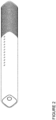
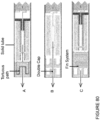
- FIG 1 shows a conventional personal vapouriser ('PV').
- the PV includes the following key components: a 'juice' or 'e-liquid' delivery and container system, called a cartridge (A), and an atomizer (B) for vapourising the juice, and a power source (C) to power the atomiser.
- the cartridge also forms the mouthpiece.
- a typical design as shown in Figure 1 , requires the battery (C) to be screwed into the atomiser (B), and the cartridge (A) is then pushed onto the free end of the atomiser B. When the cartridge is fully consumed, the user discards the used cartridge and replaces it with a new one.
- An alternative design sees the cartridge as user-refillable, typically from a small bottle of e-liquid.
- Section C User-replaceable e-liquid cartridge
- the PV can be stored in the case whenever it is not being used, and the case may operate to re-fill the PV from its user-replaceable cartridge and also re-charge the PV, the PV can always be in its fully re-filled and re-charged state whenever it is removed from the case. There is no longer any need for the user to carry around spare batteries for the PV or small re-fill bottles of e-liquid.
- This system is designed to re-fill and re-charge a PV many thousands of times without damaging either case or PV.
- This system gives the user an e-cigarette PV with the form factor of a conventional cigarette, and with the performance and user experience (e.g. vapour intensity) of a large modding kit-type PV, but with none of the inconvenience of dis-assembling the PV to re-fill the PV with e-liquid from a small bottle.
- This system also replicates the rituals of handling an object similar in size to a packet of twenty cigarettes, of opening that packet and withdrawing a cigarette; and the tactile familiarity of holding a cigarette sized object and inhaling from it. This combination is we believe key to the large-scale consumer adoption of e-cigarettes.
- the case implements a number of useful features: Feature 1. Combined re-charge and re-fill storage and carrying case Feature 2. Case with movable PV holder Feature 3. Re-Filling the PV Feature 4. PV Locking mechanism Feature 5. Data connectivity Feature 6. E-fulfilment
- Appendix 1 collects these features into a consolidated summary.
- a portable, personal storage and carrying case for an e-liquid e-cigarette PV in which the case includes: (a) a power source for re-charging a rechargeable battery in the PV; (b) a reservoir for holding e-liquid; and (c) a fluid transfer system adapted to transfer e-liquid from the reservoir to a chamber in the PV.
- the reservoir for holding e-liquid is, in one implementation, a user-replaceable e-liquid cartridge.
- this approach is key to an e-cigarette PV with the form factor of a conventional cigarette, and with the performance and user experience of a large modding kit-type PV: re-filling and re-charging of the PV is fast and convenient, since it can occur readily and easily whenever the user returns the PV to its case.
- the e-liquid cartridge in the case requires relatively infrequent (e.g. weekly) but fast, and mess-free replacement; it is far easier than re-filling manually by squeezing e-liquid from a small bottle. It may also have a simple relationship with conventional cigarette consumption (e.g. 'one hundred cigarettes in a case').
- an effective e-liquid PV consumes a significant amount of e-liquid and also current.
- Cigalites have not sold well in the market because they permit neither high e-liquid consumption nor high current. Cases that can merely re-charge a PV are not good enough because the PVs need to be frequently re-filled with e-liquid, which means dis-assembling them, which is messy and inconvenient.
- a portable, personal storage and carrying case for an e-liquid e-cigarette PV in which moving a movable holder or chassis, into which the PV has been inserted, brings electrical charging contacts on the PV into direct or indirect engagement with electrical charging contacts in the case that are connected to a power source, such as a rechargeable battery in the case.
- the feature is: A portable, personal storage and carrying case for an e-liquid e-cigarette PV which re-fills the PV with e-liquid if the PV is inserted, fully or in part, into the case, whilst maintaining the PV whole and intact.
- the design is robust and can be used for thousands of re-filling operations (as opposed to a very small number with a needle that punctures a rubber septum).
- a portable, personal storage and carrying case for an e-liquid e-cigarette PV which re-fills the PV using a fluid transfer system, such as a pump activated by depressing and releasing the entire, complete PV, whilst the PV is held in a holder of the case in accurate alignment with the fluid transfer mechanism.
- a fluid transfer system such as a pump activated by depressing and releasing the entire, complete PV
- a holder to hold the PV in accurate alignment with a fluid transfer system is highly desirable to minimise leakage and to ensure optimum performance of the e-liquid fluid transfer mechanism, particularly where that mechanism is a pump activated by relative motion of the PV against the pump, since if the PV is not aligned correctly (e.g. along the longitudinal axis of the pump nozzle), the pump may not operate efficiently and there may be leakage.
- a related high-level feature is: An e-liquid e-cigarette PV adapted to be re-filled with e-liquid when inserted into a case, in which the PV includes an e-liquid filling aperture positioned centrally along the main axis of the PV to minimise any off-centre forces that could otherwise compromise e-liquid sealing.
- the case includes a user-replaceable cartridge
- the cartridge capacity will be much greater than the PV's e-liquid chamber (for example, 10 ml for the user-replaceable cartridge as compared to 1 or 2ml in the PV chamber)
- replacement of the cartridge happens relatively infrequently - typically once every 5 days for a user replicating smoking 20 cigarettes a day. That also gives the user an easy to grasp measure of the effectiveness of any nicotine reduction program they are following - moving progressively from replacing a cartridge from every 5 days, to every 6 days, to every 7 days etc. For many ordinary users, this is an easy metric to follow.
- a portable, personal storage and carrying case for an e-liquid e-cigarette PV which is adapted to lock the PV securely in a charging position; and when the PV is locked in the charging position, then electrical charging contacts on the PV are in direct or indirect engagement with electrical charging contacts in the case that are connected to a power source, such as a rechargeable battery, in the case.
- a portable, personal storage and carrying case for an e-liquid e-cigarette PV in which the case includes (a) user-replaceable e-liquid cartridge; and (b) a fluid transfer system adapted to transfer e-liquid from the cartridge to a chamber in the PV; in which the case includes a data processor that controls sending a signal requesting a replacement for the user-replaceable e-liquid cartridge in the case.
- Enabling the case to send a request for a replacement e-liquid cartridge is very convenient for the user and also ensures that replacement cartridges are supplied in a timely manner - this is especially important when the user is on a tobacco or nicotine reduction programme since if the case runs out of e-liquid, then the user may well be tempted back to using cigarettes. So the efficacy of adopting this system as a cigarette replacement (and health concerns with cigarettes is overwhelmingly the reason given for e-cigarette adoption) benefits greatly from the timely, automatic, background ordering and supply direct to the end-user of replacement cartridges.
- the high-level feature is: Method used in portable, personal storage and carrying case adapted specifically for a refillable e-cigarette PV and that re-fills and re-charges the PV, the method including the steps of the case (a) transferring e-liquid from a user-replaceable e-liquid cartridge to the PV and (b) automatically sending a signal requesting a replacement for the user-replaceable e-liquid cartridge to an e-fulfilment platform, either directly or via a connected smartphone.
- the method may include the steps of the case (a) detecting the level of or quantity of e-liquid in a user-replaceable e-liquid cartridge in the case and (b) automatically sending a signal requesting a replacement for the user-replaceable e-liquid cartridge to an e-fulfilment platform, either directly or via a connected smartphone.
- This feature is the method that is associated with Feature 5 and the same advantages apply. Note that 'detecting the level of or quantity of e-liquid in a user-replaceable e-liquid cartridge in the case' could be direct, or could be indirect, such as inferred from the number of re-fills of the PV that have been completed with that cartridge, or the total number of inhalations made with that cartridge.
- Feature 1 Combined re-charge and re-fill storage and carrying case
- Feature 2 Case with movable PV holder
- Feature 3 Re-Filling the PV Feature 4: PV Locking mechanism
- a portable charging device for replenishing the e-liquid or vapour fluid of an e-cigarette PV comprises: an e-liquid reservoir for storing multiple dosages of e-liquid; and a refill mechanism configured to engage with the e-cigarette PV to deliver a dose of e-liquid from the reservoir to the e-cigarette PV.
- Embodiments may provide a re-filling case for refuelling the e-cigarette PV with single dose (or predetermined by end user) multiple doses of e-liquid.
- the e-liquid may be supplied to the e-cigarette PV from a tank in the charging and re-filling case holding a larger reserve of e-liquid.
- the tank may be a user-replaceable cartridge.
- a single dose of e-liquid delivered to the PV may be equivalent to a single measure of substance (such as the quantum of nicotine inhaled in one ordinary cigarette).
- a single measure of substance such as the quantum of nicotine inhaled in one ordinary cigarette.
- 0.1ml is delivered using the micro-pump design described later in this section with each pumping action; this is equivalent to approximately ten puffs of a cigarette.
- the e-liquid chamber in the PV typically holds between 1ml and 3ml of e-liquid, very roughly equivalent to between ten and thirty cigarettes.
- the fluid reservoir in the charging and re-filling case may store multiple dosages of e-liquid; the amount of e-liquid stored in the reservoir can be 10ml and is hence significantly greater than the fluid in a conventional cartridge or vial inserted into a conventional electronic cigarette.
- Re-filling the PV occurs easily and quickly whenever the user inserts the PV back into the carrying case. This is not only more convenient for the end-user, but also significantly reduces waste.
- the cartridges are ideally fully recyclable.
- a high-capacity e-liquid cartridge that is easily user-replaceable is especially important in a relatively low voltage, low resistance (e.g. closer to 3.3V than 5V; resistance closer to 2 ohms than 2.8 ohms or higher - typically 2.4 ohms - 1.9 ohms for 3.3V) since e-liquid consumption by the PV can be quite high.
- This high consumption would, with a conventional PV design be highly inconvenient because of the need to disassemble the PV and manually drip e-liquid into a small reservoir by squeezing a bottle of e-liquid. But it is no longer a problem because of the ease of re-filling the PV with e-liquid whenever it is slotted back into the case.
- a user is also now able to monitor use of the PV (and hence nicotine use) in a similar way to conventional cigarette consumption.
- a single dose may be equivalent to the amount of e-liquid required to simulate nicotine consumption equivalent to a single tobacco cigarette.
- pressing the PV down just once against the micro-pump causes approximately 0.1ml to be transferred from the case to the PV; this is approximately equivalent to ten puffs of a cigarette.
- the user could hence pump the PV down just once to transfer e-liquid equivalent to a single cigarette, or say five times for five cigarettes, or ten times for ten cigarettes.
- the volume of e-liquid stored in the PV chamber may be equivalent to the volume of e-liquid required for an electronic cigarette to simulate a pack of twenty tobacco cigarettes. Therefore, the user may be able to conveniently regulate their consumption of nicotine via the PV.
- the maximum capacity of the e-liquid chamber in the PV could be 2ml, and hence very approximately equivalent to twenty cigarettes. This easy to understand equivalence to conventional cigarettes is important in enabling users to gauge their useage and hence important for nicotine reduction useage; users find correlating useage of conventional e-cigarettes to their previous tobacco consumption difficult and this lack of transparency inhibits broader adoption of e-cigarettes, despite the significant body of scientific opinion that holds e-cigarettes to be very considerably safer than conventional cigarettes.
- a single dose may also be any other quantity set as equivalent to a single dose, for example by the end-user, or automatically by the PV or its case if for example the end-user is following a nicotine reduction program.
- Embodiments may provide a rechargeable case battery where the portable charging and re-filling case is adapted to allow the PV to recharge its battery from the rechargeable case battery.
- the portable charging and re-filling case may offer the advantage that a user is able to simultaneously refill the PV with e-liquid and also recharge the battery of the PV. This ensures that, whenever the PV is withdrawn from the case, it can have sufficient e-liquid and power to provide a good vaping experience.
- the portable charging and re-filling case may comprise a PV holder for housing the PV.
- the holder may support the PV in a specific position, provide storage, and enable refilling and charging of the PV.
- the PV holder may comprise a biasing means for receiving a PV in a support position.
- the biasing means may be arranged such that depressing the PV causes the biasing means to allow the PV to engage with the refill mechanism, in a refill position.
- To refill the PV with a dose of vapour liquid the PV may be inserted into the holder.
- the holder may be a drawer such that when the PV is placed in the drawer, pushing the PV down allows the PV to engage with the refill mechanism so that e-liquid is pumped into the PV, filling the e-liquid chamber of the PV with one dose of e-liquid.
- the PV holder may be rotatably connected to the portable charging and re-filling case such that the PV holder can move between an open and closed configuration, the open and closed positions having corresponding PV positions, wherein in the closed configuration the PV engages with the refill mechanism to receive a dose of e-liquid and in the open configuration the PV is disengaged from the refill mechanism.
- the refill mechanism may comprise a pump.
- interaction between the PV and the refill mechanism may cause the pump to deliver a measured dose of e-liquid to the PV.
- the refill mechanism may comprise a refill valve.
- the refill mechanism may be electronically controlled. A more detailed walk-through of the e-liquid transfer mechanism will be given later.
- the portable charging device or case may comprise a counter/measuring system for counting the number of times the PV has been refilled from the e-liquid reservoir.
- the counter may be resettable and the portable charging and re-filling case may display a value provided by the counter corresponding to the number of times the PV has been refilled from the e-liquid reservoir in the case.
- the value may be the number of times the PV has been refilled from the reservoir since the last time it was reset, or it may be the total number of times a dose of e-liquid has been supplied by the reservoir by the refill mechanism.
- the data may be displayed or stored on a processor within the portable charging and re-filling case to be transmitted by wire or wirelessly to a secondary device for analysis and display, such as a smartphone, a wearable device, a portable computer or directly to the internet.
- a secondary device for analysis and display such as a smartphone, a wearable device, a portable computer or directly to the internet.
- monitoring of usage may be used to determine when the e-liquid in the reservoir is nearly depleted and thus prompt the replacement of the fluid reservoir (by automatically ordering a replacement (or a week or a month's worth of replacements, or some other quantity, at the user's option) from an e-fulfilment platform that will then deliver direct to the user, or advising the user that a replacement will be needed, for example).
- Embodiments may be further adapted to vary the amount of e-liquid in a single dose, and such variation may be based on prior usage of the PV (as monitored by a counter for example).
- the amount of e-liquid (or the concentration within the vapour fluid) in a delivered dose may be gradually reduced over time, helping a user to reduce consumption of a substance in the vapour fluid (such as nicotine or caffeine, for example).
- a substance in the vapour fluid such as nicotine or caffeine, for example.
- an embodiment may moderate the amount of e-liquid in a single dose such that the desired reduction in consumption is achieved automatically, and over a set period of time or following a specific cessation program.
- the e-liquid reservoir may be a liquid cartridge which is removable from the portable charging and re-filling case such that it can be easily and quickly replaced by a user, without mess or risk of spillage. Therefore, when the e-liquid reservoir is depleted a user may insert a new liquid cartridge so that the reservoir is replete.
- the PV may comprise a liquid chamber for holding a dose of e-liquid, wherein the PV is adapted to engage with the portable charging and re-filling case in order to receive a dose of e-liquid from the fluid reservoir.
- the PV may comprise a PV valve.
- Engagement of the PV valve and refill valve may allow a dose of e-liquid to be pumped from the reservoir of the portable charging and re-filling case to the fluid chamber of the PV. Therefore, when the PV is in or moved to a refill position, a dose of e-liquid may be delivered to the PV.
- the PV valve When the PV is not engaged with the refill mechanism, the PV valve may be closed so that the e-liquid is stored in the PV.
- the portable charging and re-filling case 100 houses a fluid reservoir 3 and a rechargeable case battery 68 both of which are user-removable and replaceable.
- the PV holder or receptacle chassis 2 is a holder that is sized to securely hold the PV 1; it is shown in an open configuration and is adapted to store the electronic cigarette 1 or any other PV in a specific position that enables the PV 1 to accurately engage with and align against electrical charging contacts, data transfer contacts and e-liquid re-filling nozzle that are all in the case.
- the PV holder or receptacle chassis 2 in this embodiment is pivotally attached to the main body of the portable charging and re-filling case 100 such that in a closed configuration the PV 1 is stored securely within the casing of the portable charging and refilling case 100.
- the e-cigarette PV 1 is placed in the electronic PV holder or receptacle chassis 2 and the chassis 2 is then moved to the closed configuration in order to store and/or refill the e-cigarette PV 1.
- the electronic cigarette 1 In the closed configuration, the electronic cigarette 1 is in a refill position and can be depressed to engage with a fluid transfer mechanism to receive a dose of e-liquid from the fluid i.e. e-liquid reservoir 3 in the case 100 (typically, 0.1ml is pumped across, as noted above, for each downwards pumping action).
- the electronic cigarette 1 may be refuelled upon insertion into the PV holder 2 using some other fluid transfer action, such as a pressurised pump, electrical pump, peristaltic pump etc.
- the electronic cigarette 1 may also recharge not only its e-fluid chamber but also its internal battery 59 from the recharge case 100. This offers a user an advantage, in that it is no longer necessary to carry spare cartridges of e-liquid in order to refill the electronic cigarette 1 with e-liquid, or spare batteries to power the PV, as re-filling and re-charging can be achieved directly and without mess from the portable charging and re-filling case 100.
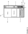
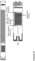
- FIG. 7 shows, at a schematic level, an example of the portable charging and refilling case 100 in cross section, and an electronic cigarette 1 for use with the portable charging and re-filling case 100.
- the e-liquid chamber of the electronic cigarette 1 is adapted to receive and store a single dose of e-liquid fluid.
- the reservoir 3 of the portable charging and re-filling case 100 stores multiple doses of e-liquid and is connected to a dosed pump 4.
- the pump 4 includes a valve 34 and valve seals 13 & 14 and a bias spring 87. When the pump 4 is actuated, a dose of e-liquid is delivered from the portable charging and re-filling case 100 to the e-liquid chamber of the electronic cigarette 1 through hollow shaft 61.
- the electronic cigarette 1 is placed into the PV holder 2 in a support position. In the support position, the electronic cigarette is disengaged from the refill mechanism. In an embodiment, a biasing member 87 prevents the electronic cigarette 1 from engaging with the refill mechanism 4 such that the electronic cigarette is maintained in the support position.
- the electronic cigarette 1 is depressed. Depression of the electronic cigarette 1 overcomes the biasing force provided by the biasing member 87 and enables the electronic cigarette 1 to move to a refill position, or to re-fill by virtue of being depressed downwards.
- a counter (not shown; part of the electronics in the case) monitors the number of doses dispensed by the refill mechanism 4 and displays the value on a display in the case, and/or transmits by wire (e.g. USB) or wireless (e.g.. Bluetooth) the usage data to a secondary device (e.g. a smartphone) with a display, to the user.
- the counter may display the number of doses dispensed by the refill mechanism 4 since the counter was last reset and/or may display the total number of doses the refill mechanism 4 has dispensed. This offers the user the advantage of having the opportunity to monitor their consumption.
- the counter may indicate to a user when the fluid reservoir 3 holds a lower volume than a threshold value (e.g. when the vapour fluid in the reservoir is nearly depleted).
- Detection that the amount of vapour fluid in the reservoir is below the threshold value may be used to prompt the replacement of the fluid reservoir, by automatically ordering the delivery of a replacement fluid reservoir for example.
- the chassis 2 is just a holder for the PV and the pump 4 mechanism; in the more detailed walk-through of the working device we will provide later in this Section A (e.g. Figures 26 - 31 ) the chassis also supports the case battery, electronics and e-liquid reservoir; this simplifies the connection between pump and e-liquid reservoir, eliminating the need for a flexible e-liquid pipe.
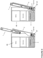
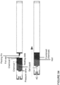
- FIG 8 illustrates a further example of the portable charging and re-filling case 100 in use.
- the PV holder 2 is rotatably connected to the portable charging and re-filling case 100 and swivels to an open configuration to accept the electronic cigarette 1.
- the electronic cigarette 1 is placed into the PV holder 2 when the PV holder 2 is in the open configuration.
- the PV holder 2 is then moved to a closed configuration.
- the position of the electronic cigarette 1 in the closed configuration is such that the electronic cigarette 1 engages with the refill mechanism 4 to receive a specific or predetermined dose of e-liquid.
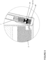
- FIG 9 shows the interaction between the electronic cigarette 1 and the refill mechanism 4 in more detail.
- the refill mechanism 4 includes a hollow stem shaft 61 which engages with the electronic cigarette 1 when the electronic cigarette 1 is in the refill position. Pushing the PV 1 down, into the refill position causes vapour fluid to be pumped from the fluid reservoir 3 to the electronic cigarette 1.
- the refill mechanism 4 is electronically controlled.
- the pump 4 may be actuated or the refill valve 34 may open in response to a received signal.
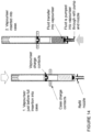
- Figure 10 shows the electronic cigarette 1 stored in the portable charging and refilling case 100 in the refill position.
- e-liquid is pumped from the fluid reservoir 3 to the liquid chamber of the electronic cigarette 1 to refuel the electronic cigarette 1.
- this can be achieved by the top 32 of the PV being pushed downwards by a camming action as the holder 2 is closed, overcoming bias spring 87.
- an electronic pump might be activated once the PV is in the closed configuration.
- the electronic cigarette 1 may recharge its battery 59 from the rechargeable case battery 68 of the portable charging and re-filling case 100.
- an electronic cigarette 1 for use with the portable charging and re-filling case 100.
- the electronic cigarette 1 has a liquid chamber 48 for storing a dose of e-liquid.
- the liquid chamber is connected to a PV valve 29.
- the PV valve 29 opens to allow a dose of e-liquid to enter the chamber 48.
- the PV valve 29 is closed so that the vapour liquid is stored in the liquid chamber and does not leak out.
- the portable charging and re-filling case 100 is not limited in shape, and may not be rectangular.
- the refill mechanism 4 may not comprise a pump but some other kind of fluid transfer mechanism, and refilling of the electronic cigarette 1 with electronic cigarette fluid may be achieved by an alternative means.
- the charging function may also occur using a charging station that is fixed (e.g. desktop based; plugged into a power socket) rather than using a portable charging and re-filling case.
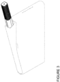
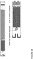
- Figure 12 shows an embodiment where the PV holder is formed as a recess in the side the portable charging and re-filling case 100.
- the recess is adapted to receive a PV 1.
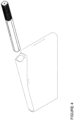
- FIG 13 shows an alternative embodiment wherein the PV holder is formed as a cylindrical hollow barrel along the central longitudinal axis of a circular portable charging and re-filling case 100.
- a PV may be placed into the hollow barrel in a support position (as depicted in Figure 13 , left hand-side ). In the support position, the PV is disengaged from the refill mechanism.
- a biasing member not shown prevents the PV from engaging with the refill mechanism such that the PV is in a support position.
- the PV is pushed further in to the hollow barrel.
- Such further depression of the PV overcomes a biasing force provided by a biasing member and enables the PV to move to a refill position as depicted in Figure 13 , right hand-side.
- the PV engages with the refill mechanism to receive a dose of e-liquid from the reservoir of the portable charging and re-filling case 100.
- Figure 14 shows that when the e-cigarette PV is depressed down onto the refill nozzle of the case, then case charge contacts electrically contact e-cigarette PV charge contacts, electrically connecting the electronic cigarette to the case battery so that the electronic cigarette can recharge its internal battery from the rechargeable case battery; hence, both the PV's battery as well as its e-liquid reservoir are replenished when inserted into the case.
- the electronic contacts can also provide the mechanisms through which the data is transferred from the PV to the portable case.
- Non-pressurised pump technology can be used in this design to dispense a dose of a given volume of e-liquid.
- the device is made up of a single pump with a hollow control tube.
- the pump has a chamber with a predefined volume of e-liquid held for dispensing.
- the e-liquid is forced under pressure from the e-liquid pump out through the pump nozzle and via a one way valve into the PV chamber.
- the pump As the pump is released, it returns to its original state under a spring mechanism and in doing so draws liquid through the hollow control tube into the liquid chamber to replenish the pump so that it is ready to transfer e-liquid into the PV on the next down-stroke of the PV.
- the pump is preferably a pump termed a "high delivery" pump, which makes it possible to fill the bottle by actuating the pump only once.
- a pump is suitably used having a delivery of 0.1ml per shot in order to feed the PV chamber.
- the pump dosage volume can be predefined or variable dependent upon usage requirements.
- Pressurised pump technology may also be used: the liquid cartridge would be pressurised like a small aerosol to move predetermined volumes of liquid.
- the vapouriser would depress a valve that contains a liquid chamber. As the system is pressurised no 'pump' is required, instead fluid moves straight from the cartridge to the PV chamber, which is fixed in volume.
- the system comprises several main components, a Personal Vaporiser 1 and a portable, personal re-filling and re-charging Case 100.
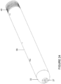
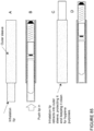
- Figure 20 shows a working, test prototype (i.e. not with the industrial design finishing of the final consumer product). The remainder of the engineering drawings will also relate to this test prototype.
- the case 100 is shown with a left hand side 6 and a right hand side 7.
- the case includes a Receptacle Chassis 2; the Receptacle Chassis 2 serves as the PV holder, securely holding the PV 1 when it is inserted into the case 6, 7.
- the Receptacle Chassis also serves as the mount on which are placed the e-liquid reservoir 3, fluid transfer mechanism 4, battery 68 and related components.
- the entire Receptacle Chassis 2 rotates 15° about a Pivot Screw 18 inside a Case 6, 7 with the Receptacle Chassis 2 being Positively Biased Closed, 0° position, by a Leaf Spring 17 (first shown in Figure 26 ) attached to the Receptacle Chassis 2 via Screws 35 (first shown in Figure 26 ).
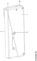
- Figure 20 shows an isometric view of the case 100 with the Receptacle Chassis 2 fully closed
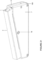
- Figure 21 shows an isometric view of case 100 with the Receptacle Chassis 2 rotated open 15° and showing the top of a PV 1 fully inserted into the PV holder portion of the Receptacle Chassis 2.
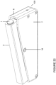
- Figure 22 shows an isometric view of the case 100 with PV 1 slightly raised and ready for the user to withdraw from the case 100. The PV 1 has been heated to its operational temperature using the battery in the case and is 'ready to vape'.
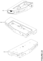
- Figure 23 shows an isometric view of the Receptacle Chassis 2 on its own.
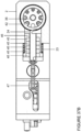
- Figure 24 shows an isometric view of the PV 1 (again, note that this is the test prototype and not the consumer version).
- the PV 1 has a Tip 32; at the end of the Tip 32 is a centrally positioned aperture through which e-fluid passes when re-filling the PV 1.
- a Seal Inlet 27 seals the aperture against the pump nozzle of the fluid transfer mechanism to prevent spillage or leakage of e-liquid.
- Three radially disposed vents are positioned around this central aperture; these are the vents through which vapour is inhaled.
- a Ring Connector Assembly 49 at the other end of the PV 1 provides electrical power and data contacts that engage with electrical power and data contacts in the Case 100.
- Tube body 56 contains all components.
- Figure 25 shows a sectioned view of the PV 1.
- Seal Inlet 27 seals the PV against a fluid transfer nozzle in the case;
- Valve 29 enables e-liquid to pass up into the PV and prevents it leaking out since it is biased in the closed position by Spring 30.
- Valve 29 only opens when the force exerted by the fluid, driven by the fluid transfer mechanism, exceeds the force of Spring 30.
- Grub screws 31 secures the Valve 29 and Spring 30 in position.
- An O-Ring 28 seals Tip 32 against the body of the PV 1.
- the atomiser includes a Coil and Wick Assembly 52 with a Vapouriser End Cap 50 and Vapouriser Insulating Sleeve 51.
- Fluid Chamber 48 stores e-liquid; the lengths of wicking element running parallel to the body of the PV are fully immersed in e-liquid in Fluid Chamber 48; the wicking element running perpendicular to the body of the PV, and around which the electrical heating element is wound, is not however immersed in e-liquid, but draws e-liquid up from the limbs that are fully immersed. Further O-Ring 28 seal the e-liquid Chamber 48 from the rest of the Tube Body 56 of the PV 1. The Outer Body 53 of the PV surrounds the vapouriser.
- Vaporiser Outer Body 53 and Vaporiser Inner Body 55 are insulated by Bush Vaporiser Body 54. Current is passed to the Vaporiser Inner Body 55 via a wire connected to PCB 60. One leg of the Coil 52 contacts the Vaporiser Inner Body 55, the other Coil Leg contacts Vaporiser Outer Body 53. This can be seen most clearly from Figure 62 .
- the Vaporiser Outer Body 53 is connected to Earth.
- a Pressure Sensor/Transducer 58 is mounted behind the Vaporiser Unit in the Pressure Sensor Housing 57. This is wired to the PCB 60.
- An PCB 60 An iPad Chip 66 mounted to the PCB 60 is used to monitor, control, set and feedback information pertaining to the vaping functionality.
- a 3.7V 140mAh LiPo Battery 59 sits on the PCB 60.
- the far end of the PCB 60 is wired to Ring Connector 49 with 4 connections - 1 Power, 1 Earth, 2 Signal.
- Ring Connector 49 is made up of alternating Ring Contacts 42 and Insulation Rings 43, and is mounted on Screw 44 and terminates with End Cap 36.
- the Pressure Sensor/Transducer 58 activates, causing current to be sent to the Coil/Wick Assembly 52.
- the Coil heats the vaping fluid soaked wick, giving off vapour which entrains into the air stream.
- a unitary (and hence very strong) stainless steel Tube 56 houses all the parts mentioned above with a cut out to allow the RGB LED 64 to display the Status of the PV 1 for both battery power and vaping fluid level. A further small hole sits above the Reset Switch 65 mounted to the PCB 60.
- the PV 1 charges its 140mAh Battery via the Ring Connector 49. Information is also fed back to the PCB Main Case 16 via 2 of the connections on the Ring Connector 49.
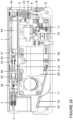
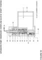
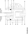
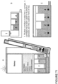
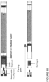
- FIG. 26 shows a sectioned view of the case 100 with the Receptacle Chassis 2 fully closed into the case 100; the PV 1 is omitted for clarity.
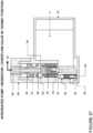
- Figure 27 shows a sectioned view of case 100 with the Receptacle Chassis 2 rotated open 15, again with no PV inserted for clarity.
- Receptacle Chassis 2 rotates 15°, using hand pressure, from its closed position, shown in Figure 26 , to its "Open" position shown in Figure 27 , with Leaf Spring 17 supplying a resistive force, bearing against Case 6 & 7 inner walls.
- Figure 27 shows clearly how all critical components needed in the case 100 are mounted on the Receptacle Chassis 2.
- Key elements are the e-liquid pump 4, which sits in a void in the e-liquid cartridge 3.
- a hollow stem shaft 61 protrudes from one end of the pump 4, biased upwards by a spring; when a PV is depressed against this hollow stem shaft 61, it depresses that hollow stem shaft 61 downwards, forcing e-liquid within the pump 4 to travel up the hollow stem shaft 61 into the PV; the e-liquid cannot return back into the reservoir 3 because a ball valve 34 at the base of the pump 4 closes.
- the rechargeable battery 68 and a solenoid 22 that triggers an interlock mechanism, a lever or pawl 10 with a tooth at one end that rests against a sliding contact block 5.
- a lever or pawl 10 with a tooth at one end that rests against a sliding contact block 5.
- the pawl rises and locks against an edge of the sliding contact block 5, preventing it from moving back into the case 100 and hence locking the PV into position.
- Various PCB components are also shown mounted on the Receptacle Chassis 2, such as Microswitches 70, and PCB 16.
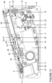
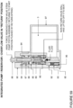
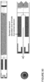
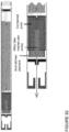
- Figure 29 shows the device in activated mode, with solenoid 22 activated and pawl/lever 10 activated, locking sliding contact block 5 in position.
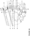
- Figure 30 shows the pre-heat mode: the Receptacle Chassis 2 is now fully opened; the PV 1 is locked in position and the sliding contact block 5 is also locked in position by pawl/lever 10; current is drawn from case battery 68 to heat the coil in the Coil and Wick Assembly 52 in PV 1.
- solenoid 22 releases pawl/lever 10 and sliding contact block 5 withdraws away from the PV 1, which is then biased to rise up slightly out of the case 100 by shaft 61 in pump 4, as shown in Figure 31 . So Figure 31 shows the activated mode.
- Figures 32 - 37 show the operation of the 4 Way Sliding Contact Block 5.
- the 4 Way Sliding Contact Block 5 connects Power, Earth and 2 Signal Input/Outputs from the PCB Main Case 16 to the PV PCB 60.
- a mechanical Interlock between the 4 Way Sliding Contact Block 5 and the PV 1 is incorporated in the design: the body 46 of the 4 Way Sliding Contact Block has a finger protrusion which engages with an undercut on the PV ring connector 49 providing the interlock facility. This is clearest when comparing Figures 32- 34 , which show the finger protrusion locking into the PV, and Figure 35 , which shows the 4 Way Sliding Contact Block 5 after it has slid back into the case and the PV 1 is now released.
- the 4 Way Sliding Contact Block 5 is normally biased away from and out of contact with the Ring Connector 49 on the PV by a helical Spring 23 when mounted in the Receptacle Chassis 2 in the Open 15° position and with the Pawl/Lever in the disengaged 6° position - Figure 35 .
- the 4 Way Sliding Contact Block 5 is pushed into contact with the PV Ring Connector 49 when the Receptacle Chassis 2 is rotated back into the Case 6 & 7 to the Closed 0° position - e.g. when storing the PV, as shown in Figures 32 - 33 .
- a Cam Block 8 is fastened to the Case 6 & 7.
- the Spring 23 biasing the 4 Way Sliding Contact Block 5 is compressed as the 4 Way Sliding Contact Block 5 bears against the Cam Block 8.
- the 4 Way Sliding Contact Block comprises 4 Contact Fingers 24 - Figure 36 and 37 show these clearly, housed in Body - 4 Way Sliding Contact Block 46 and five Support Rings 45. Four wires are connected to the Contact Fingers 24. These connect back to pads on PCB Main Case 16.
- the 4 Way Sliding Contact Block 5 is limited to 2mm in its linear travel by Guide Plate 9.
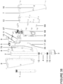
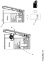
- FIG 38 is an exploded view of the case 100 and its components, the detailed operation of which has been described above.
- the Receptacle Chassis 2 forms the main housing for all the major components. When the device is built a Cover 12 is screwed into place.
- the Receptacle Chassis houses the PCB Main Case 16. This has a 650mAh battery 68 connected to it and a Micro USB Connector 67 for re-charging the main battery and communications.
- the PCB Main Case 16 fastens to the Receptacle Chassis 2 by means of PCB Standoffs 69. These also serve as the fixing holes for the Lid 12.
- Solenoid 22 is attached to the Receptacle Chassis 2 via the Solenoid Mounting Block 11, adjustment is provided via a slotted screw hole in the Solenoid Mounting Block 11.
- the PCB Main Case 16 has an Engineering Chip mounted to it controlling all electrical functions associated with the device. Consequently, it is possible for the user to alter the power delivered to the atomiser and hence customise the vaping experience to their specific preferences.
- the PCB Chip can be controlled from a connected smartphone app., communicating with the chicken Chip over Bluetooth LE. The following kinds of data could be tracked by the iOS Chip and relayed to the user's connected smartphone app.:
- a Display is provided in the Receptacle Chassis to communicate the Device status to the user.
- Fluid transfer operation is as follows: the PV 1 is dropped into the Receptacle Chassis aperturec2 where it comes to a stop against the top of the Pump 4. Depressing the PV 1 further against the Pump 4 causes a further 3mm linear travel & the transfer of a metered dose of e-liquid vaping fluid from the Receptacle Chassis 2 to the PV 1. Approximately 0.1 ml of e-liquid is transferred per pumping action.
- the reservoir in the PV can typically store 1 or 2ml of e-liquid.
- the PV 1 Fluid Chamber 48 can be charged by repeatedly pushing the PV 1 down against the Pump 4.
- the case 100 can accept a custom designed 5ml Fluid Reservoir 3 which can be fitted and withdrawn from the Receptacle Chassis 2 by pushing in and pulling out.
- Other sizes of Fluid Reservoir 3 are also possible, typically up to 10ml. It is retained by means of a Moulded Rim 62 and Sealed to the Pump 4 my means of an integrally Moulded Lip Seal 63. Different types of Vaping Fluid can be easily changed with no disassembly of the Device required.
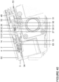
- Figure 40 shows the loading - discharging position, with the Receptacle Chassis 2 at the Open 15° position.
- Pump 4 is mounted into Receptacle Chassis 2 and is sandwiched between Valve Mounting Cup 13 & Valve Mounting Cap 14.
- Reservoir 3 pushes into a slot in Receptacle Chassis 2 from beneath, with Moulded Rim 62 snapping into an undercut section in Receptacle Chassis 2.
- Reservoir Gasket 15 applies pressure on Moulded Rim 62 to maintain contact with the undercut.
- Reservoir 3 can be readily inserted and withdrawn by the user.
- Reservoir 3 has moulded Lip Seal 63 as an integral feature which seals against Pump 4.
- PV 1 is resting against Hollow Stem Shaft 61 of pump 4, but has not yet started to depress the Hollow Stem Shaft 61.
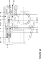
- FIG 41 shows the re-filling position - with Receptacle Chassis 2 still at the Open 15° position.
- PV 1 is now shown flush with Valve Mounting Cup 13 & Pump 4.
- Hollow Stem Shaft 61 has been depressed down 3mm by the PV 1.
- Fluid passes up Pump 4 Hollow Stem Shaft 61 and Opens Valve 29 in PV Tip 32.
- Seal 27 bears against top of Pump 4 Hollow Stem Shaft 61.
- Valve 29 is moved off its seat by the pressure of the transferring e-liquid fluid.
- Spring 30 returns Valve 29 to its seat after pressure has equalised with Vaping Fluid entering Fluid Chamber 48.
- Figure 42 shows the standby position - Closed 0° position. Hollow Stem Shaft 61 is fully depressed and PV 1 is in a dormant state. E-liquid previously pumped into the PV 1 is retained with the PV 1, so that it remains ready to use.
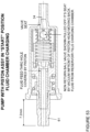
- Figure 50 shows pump 4 at its start position, ready for initial priming.
- the pump 4 has a non-return ball valve 34 at fluid inlet end 81 and a slide valve at fluid outlet end 82.
- the non-return ball valve 34 consists of a steel ball bearing that moves within a short slotted tube 83 with retaining barbs at one end and seats into a shallow taper at the other end, closest to the fluid inlet end 81.
- the slide valve consists of a through-hole 84 in the piston rod 86 which is covered and revealed by the action of the piston 85 sliding backwards and forwards over the through-hole 84.
- the pump has a piston assembly comprising a valve stem 88, a piston rod 86, a piston 85 and a bias spring 87.
- the valve stem 88 and piston rod 86 are permanently joined together and move as one.
- the piston 85 slides on the piston rod 86 and in the valve stem 88.
- a bias spring 87 keeps the piston 85 positioned forward, at the start position of its 3mm stroke, and covering the slide valve through-hole 84.
- Figure 51 shows the piston 85 at the end of its 3mm stroke; the bias spring 87 is now fully compressed, by 1.2mm. Piston return spring is now also fully compressed, by 3mm.
- the feed though-hole 84 in the piston rod 86 is exposed since the piston 85 has been forced backwards relative to the piston rod 86 by the increased hydraulic pressure, which exceeds that of the bias spring 87.
- the pressurised fluid in the fluid chamber 80 can now escape through the exposed feed-through hole 84 and up the inside of the piston rod 86 and valve stem 88, as the piston assembly completes it's stroke.
- Figure 52 shows that as the hydraulic pressure drops below the bias spring force, this allows the piston 85 to slide forwards along the piston rod 86 and cover the feed-through hole 84. Fluid chamber 80 is now sealed at both ends.
- Figure 53 shows removing the axial force on the valve stem; this allows the piston return spring 89 to send the piston assembly back to it's start point.
- a vacuum develops in the pump fluid chamber 80. This pulls the non-return ball valve 34 off it's seat, allowing fluid from the reservoir to fill the void in fluid chamber 80.
- the pump cycle is now complete. (As a preliminary step, cycling the piston assembly several times may be needed to dispel air from the fluid chamber 80 and replaces it with fluid. The fluid chamber 80 is now charged).
- the pump directly into the user-replaceable cartridge. That has some advantages - specifically, if the pump fails, then it is just the cartridge that needs to be replaced, not the entire case. Also, if the pump is part of the case, and different flavours of e-liquid are desired, that requires different cartridges to be swapped in to the case. There may some residue of the previous flavour in the pump, possibly affecting the vaping experience. Integrating the pump into the cartridge eliminates the problem of flavour tainting through previous e-liquid residue in the pump.
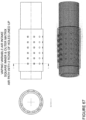
- FIG. 55 - 59 This variant is shown in Figures 55 - 59 .
- the same 0.1ml pump is used and it operation is fundamentally as described above.
- the fluid reservoir 3 has a 5ml capacity and is formed as part of a body moulding.
- the body cavity is sealed with a valve cap 90 moulding, being ultra sonically welded to the body.
- Valve cap 90 at the fluid outlet end of the combined pump and cartridge locks the pump in position and also provides guidance for the valve stem 61.
- the combined pump and cartridge includes an overflow valve. This is made up of a tapered valve seat 91 in the body moulding, a steel ball bearing 92 and return spring 93.
- the tapered valve seat 91 is at the end of a bore slightly larger than the bore of the steel ball bearing 92. There are channels cut into the bore to allow for the flow of fluid in the bypass condition.
- the taper is 180° juxtaposed from the non-return valve taper.
- the overflow valve ball 92 In normal operation, the overflow valve ball 92 remains seated in it's tapered housing kept in place by the return spring 93. If a condition arises where the hydraulic pressure in the pump fluid chamber 80 exceeds the design pressure, the overflow valve ball 92 is forced off it's seat against resistance offered from the return spring 93. Fluid can pass the steel ball 92 and return to the reservoir chamber 3 - this is the bypass condition.
- the integrated pump/reservoir/overflow valve can be in one of five different conditions:
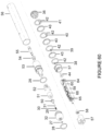
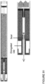
- FIG. 60 shows an exploded view of PV 1 and Figure 61 shows an isometric view of PV 1.
- Figure 62 shows one design of atomiser assembly.
- the PV 1 includes a PV Tip 32 containing Valve 29, Valve Spring 30 and Grub Screw 31.
- PV Tip 32 also has 3 concentric holes, connecting to Air Way, which allow Vaporised Liquid to be inhaled.
- the heating coil is perpendicular to the long axis of the PV 1.
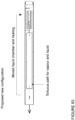
- Figure 63 shows an alternative design in which the wicking material has the same 'U' shape, but also includes a long element running along the long axis of the PV 1.
- Heating coil 98 is wound around this long element and the Coil & Wick Assembly 52 then retained by chassis 99.
- the advantage of this alternative design is that a longer heating coil 98 can be used, and airflow over the heated coil 98 should be more uniform and effective since the coil runs parallel to the airflow instead of perpendicular to it.
- the vaporiser sits behind the Tip 32, and is made up of a Coil & Wick Assembly 52, Vaporiser Outer Body 53 and Vaporiser Inner Body 55. These are insulated by Bush Vaporiser Body 54. Current is passed to the Vaporiser Inner Body 55 via a wire connected to PCB 60. One leg of the Coil 52 contacts the Vaporiser Inner Body 55, the other Coil Leg contacts Vaporiser Outer Body 53. This can be seen most clearly from Figure 62 . The Vaporiser Outer Body 53 is connected to Earth.
- a Pressure Sensor/Transducer 58 is mounted behind the Vaporiser Unit in the Pressure Sensor Housing 57. This is wired to the PCB 60.
- An PCB 60 An iPad Chip 66 mounted to the PCB 60 is used to monitor, control, set and feedback information pertaining to the Vaping Functionality.
- a 3.7V 140mAh LiPo Battery 59 sits on the PCB 60.
- the far end of the PCB 60 is wired to Ring Connector 49 with 4 connections - 1 Power, 1 Earth, 2 Signal.
- the Pressure Sensor/Transducer 58 activates, causing current to be sent to the Coil/Wick Assembly 52.
- the Coil heats the vaping fluid soaked wick, giving off vapour which entrains into the air stream.
- a unitary (and hence very strong) stainless steel Tube 56 houses all the parts mentioned above with a cut out to allow the RGB LED 64 to display the Status of the PV 1 for both battery power and vaping fluid level. A further small hole sits above the Reset Switch 65 mounted to the PCB 60.
- the PV 1 charges its 140mAh Battery via the Ring Connector 49. Information is also fed back to the PCB Main Case 16 via 2 of the connections on the Ring Connector 49.
- the Ring Connector Assembly allows the PV 1 to be placed in the Receptacle Chassis 2 in any orientation without it affecting its connectivity.
- Four Ring Contacts 42 with different length Pins 38, 39, 40, 41 soldered to them are separated by three Insulating Rings 43 which in turn are housed in End Cap - Ring Connector 36.
- This ensemble is capped with PCB Mounting Cap / Ring Connector 37 fastened with a Screw 44.
- a wire is soldered to each of the Pins 38, 39, 40, 41 which are then soldered to Pads on PCB 60.
- the Ring Connector Assembly also has 2 off 1.7mm Slots which captivate the PV PCB 60.
- the Ring Connector Assembly is a push fit in the end of the Tube Body - Vaporiser 56.
- variable air intake feature Altering the airflow allows the user to customise the vaping experience to their specific preferences; for example, an experienced vapour looking to produce large quantities of vapour with a variable voltage modding kit type PV might set the voltage used to a much higher power than normal and he would manually fix an air intake that would him to breath in a large volume of vapour. Swapping different air-intakes is generally a matter of screwing out the unwanted air intake and screwing in an air-intake with the required air-hole size(s).
- the casing comprises an inner and an outer tube; the inner tube has a matrix of air-intake holes which can be lined up with air-intake holes in an outer-tube; the user rotates the outer tube until the desired number of holes are lined up.
- the inner tube could have a regular, square-arrangement or matrix of holes consisting of 6 holes formed radially at 30° intervals repeated over 6 rows.
- the outer tube then has a square matrix of holes consisting of 6 holes formed radially at 30° intervals repeated over 6 rows. The outer tube slides over inner tube until top rows of holes coincide.
- the outer tube can be rotated in 30° increments to reveal 0, 1, 2, 3, 4, 5 or 6 columns of holes in inner tube thereby varying cross sectional area of air able to enter the vaporiser body.
- Figure 67 shows two rows of holes lined up and
- Figure 68 shows 5 rows lined up.
- FIG. 69 Another variant, shown in Figure 69 , comprises 2 tubes - inner and outer.
- the inner tube has a square matrix of holes consisting of 6 holes formed radially at 30° intervals repeated over 6 rows.
- the outer tube has helical matrix of holes consisting of 1 hole per row formed radially at 30° intervals repeated over 6 rows - 6 holes in total.
- the outer tube slides over inner tube until top rows of holes coincide.
- the outer tube can be rotated in 30° increments to reveal 0, 1, 2, 3, 4, 5 or 6 columns of holes in inner tube thereby varying cross sectional area of air able to enter the vaporiser body.
- vaping experience is a function of a number of variables, such as e-liquid constituents, power delivered to the atomiser, temperature reached, airflow etc. It is possible for the case to store different profiles, such as 'light', 'smooth', 'intense', 'maximum vapour quantity', 'maximum strength', warmer vapour', 'cooler vapour' etc. Each of these could also be a function of a specific brand of e-liquid. The user can then select on their smartphone app the specific profile and/or variables that meet their preferences.
- the specific brands of e-liquid could themselves determine specific variables of the case and PV.
- a user could select on their smartphone app to use say a 'Marlboro' brand of e-liquid, and then the case would automatically configure parameters such as power, temperature etc to give the ideal experience for that specific brand.
- the parameters could be stored in software or firmware in the case or the PV. It would also be possible to obtain an application from an app store, such as the Apple App Store, or Google Play, specific to a brand of e-liquid; this app would then automatically configure the connected case with the appropriate parameters for optimum performance for that brand of e-liquid.
- Feature 1 Combined re-charge and re-fill storage and carrying case
- Feature 2 Case with movable PV holder
- Feature 3 Re-Filling the PV Feature 4: PV Locking mechanism
- this is a portable, personal storage and carrying case for an e-liquid e-cigarette PV in which the case includes a data processor that controls sending a signal requesting a replacement for a user-replaceable e-liquid cartridge in the case.
- the related e-fulfilment method is a method used in portable, personal storage and carrying case adapted specifically for a refillable e-cigarette PV and that re-fills and re-charges the PV, the method including the steps of the case (a) transferring e-liquid from a user-replaceable e-liquid cartridge to the PV and (b) automatically sending a signal requesting a replacement for the user-replaceable e-liquid cartridge to an e-fulfilment platform, either directly or via a connected smartphone.
- the method may include the steps of the case (a) detecting the level of or quantity of e-liquid in a user-replaceable e-liquid cartridge in the case and (b) automatically sending a signal requesting a replacement for the user-replaceable e-liquid cartridge to an e-fulfilment platform, either directly or via a connected smartphone.
- detecting the level of or quantity of e-liquid in a user-replaceable e-liquid cartridge in the case' could be direct, or could be indirect, such as inferred from the number of re-fills of the PV that have been completed with that cartridge, or the total number of inhalations made with that cartridge, or any other way of intelligently determining whether a replacement cartridge should be ordered.
- Machine learning can also be deployed to analyse the user's usage patterns; for example, if the user tends to vape heavily over the weekend but quite lightly during the week, then that can be taken into account when determining when a replacement cartridge should be ordered.
- a degree of direct interaction between e-liquid vendors and end-users is possible; when a user is likely to be ordering replacement cartridge(s), then special offers, or offers for new flavours or new strengths of e-liquid can be sent (e.g. text, instant message etc) to the user, or any other way of cementing brand loyalty.
- Enabling the case to send a request for a replacement e-liquid cartridge is very convenient for the user and also ensures that replacement cartridges are supplied in a timely manner - this is especially important when the user is on a tobacco or nicotine reduction programme since if the case runs out of e-liquid, then the user may well be tempted back to using cigarettes. So the efficacy of adopting this system as a cigarette replacement (and health concerns with cigarettes is overwhelmingly the reason given for e-cigarette adoption) benefits greatly from the timely, automatic, background ordering of replacement cartridges.
- Figure 70 is a high-level schematic showing a portable re-filling case able to communicate wirelessly and also through a wired connection to a smartphone, a laptop and a modem; these devices send data via the internet or other network - this can be any of the consumption data (including how consumption varies according to the various parameters, such as part of the day/night, daily, weekly, seasonal, weather, time, location, temperature and any other factor).
- This data is especially valuable to PV vendors, especially if it can be associated with a demographic profile of the device user; that demographic profile can be entered by the user when they register their device online (e.g.
- the data can also be used by an e-fulfillment company to process the order and to provide replacement consumables (e-liquid, PV, case) to the user.
- Figure 72 shows schematically that the portable re-filling unit includes electronics componentry, such as a memory, wireless/wired connectivity, software, and a controller/processor. Also, the cartridge includes four compartments, each with a different flavor or strength of e-liquid; the case is able to monitor the consumption of e-liquid in each compartment and share that consumption data with the connected smartphone app, as well as the e-fulfillment platform.
- electronics componentry such as a memory, wireless/wired connectivity, software, and a controller/processor.
- the cartridge includes four compartments, each with a different flavor or strength of e-liquid; the case is able to monitor the consumption of e-liquid in each compartment and share that consumption data with the connected smartphone app, as well as the e-fulfillment platform.
- the re-filling unit itself can measure how much e-liquid is left in its cartridge(s) or tank(s). There are various ways of doing so:
- Preceding Section A focused on aspects of the re-filling and re-charging case.
- Section B To describing various features in the e-cigarette PV itself.
- the PV implements a number of useful features that contribute to the user experience, defined by simplicity and ease of use.
- a significant problem with conventional e-cigarette PV designs is that re-filling a cartridge reservoir is slow and can be messy; it typically requires the user to purchase small bottles of e-liquid and to carefully dis-assemble the PV and then re-fill the cartridge by lining up the nozzle of a bottle and squeezing gently. Equally, removing a spent, non-refillable cartridge and replacing it with a new cartridge, whilst not messy, is wasteful, especially as typical cartridges are not recyclable.
- the feature is a re-fillable and re-chargeable e-cigarette PV that is not disassembled in normal use for re-filling or replenishing with e-liquid and is also not disassembled in normal use for battery access or replacement or other battery interaction.
- a second aspect of this feature is a re-fillable and re-chargeable e-cigarette PV with a casing that includes a rechargeable battery, a re-fillable e-liquid reservoir and an atomiser, none of which are removable from, or separable from, any part of the casing in normal use.
- the body of the casing may be a one-piece, unitary casing (typically circular or square in profile), with components introduced from either or both ends.
- a third aspect of this feature is a re-fillable and re-chargeable e-cigarette PV designed in normal use to only be re-fillable with e-liquid and re-chargeable when inserted into or otherwise engaged with a carrying case for the PV, the carrying case being specifically adapted to re-fill and re-charge the PV.
- a fourth aspect of this feature is a re-fillable and re-chargeable e-cigarette PV with a tip that includes (a) an e-liquid filling aperture that is designed to engage an e-liquid transfer mechanism (b) one or more vapour outlets distributed around the e-liquid filling aperture; and electrical charging contacts spaced apart from the tip.
- Figure 7 shows the PV case 100 which serves also as a e-liquid re-filling unit; it includes a replaceable e-liquid cartridge 3 and a battery 68 that can re-charge the battery in the PV 1.
- Figure 7 is a cross-section view of the re-filling unit 100 and the PV 1;
- Figure 8 shows the PV 1 being inserted into the re-filling unit 100;
- Figure 9 shows the pump action dispenser in the re-filling unit 100 automatically replenishing the e-liquid reservoir in the PV 1 whilst the PV 1 is being pushed down;
- Figure 10 shows the PV 1, fully replenished, and stored in case 100 (when the PV 1 is stored in the case, PV 1 is also pushed down to activate the pump dispenser to ensure the PV 1 is fully replenished with e-liquid).
- PV 1 is not dis-assembled in normal use for re-filling the reservoir or otherwise replenishing or replacing the substance.
- the battery 5 in the re-filling unit 1 also charges the battery in the PV 1 whilst PV 1 is stored in the re-filling unit 1.
- the first pre-heat feature is a portable, personal storage and carrying case for an e-liquid e-cigarette PV that starts providing power to heat an electrical atomising element in a PV automatically when the case in which the PV is stored is opened.
- the second 'pre-heat' feature is an e-cigarette PV that automatically heats an electrical atomising element when the PV detects that it is no longer in electrical contact with the charging contacts in a portable carry case in which it is stored (e.g. when the case is opened and the PV pops up out of the case).
- the first and second pre-heat features can be combined - e.g. the first phase is for the battery in the case to provide power for pre-heating when the case is opened; the second phase is for the battery in the PV to take-over heating when it detects that the PV is no longer in contact with the electrical power contacts in the case and hence can no longer rely on power from the case. Normally, this second phase occurs only once the pressure sensor in the PV detects that the user is inhaling.
- a third pre-heat feature is a portable, personal storage and carrying case for an e-liquid e-cigarette PV which includes a locking system to lock the PV securely in a heating position during which time the PV is heating using power from a power source in the case and, after the PV has been sufficiently heated, to release the locking mechanism.
- the case automatically may move the PV to a position which allows it to be readily removed from the case by an end-user once the PV has been sufficiently heated. The user can also press the PV back down when it is in the case to initiate heating.
- a personal vapourising device storing a substance to be vapourised, the device including a means of indicating by visual cue, audible cue, touch feedback, haptic, vibration, heat or other sensory signal, or prompt, when the device has sufficiently heated the substance to a predetermined temperature or for a predetermined time, so that the device is ready for use.
- the PV (or indeed the case) may show when the PV is ready for use because heating to an operational level has been reached or heating for a predefined time has occurred. For example, a simple LED may glow when the PV is ready for inhalation.
- This kind of indicator is very useful because if the user tries to inhale before the atomizer is effectively able to create a vapour with the correct characteristics (which happens if the e-liquid is too cool and viscous), then the user experience is very poor.
- Pre-heating can also start when the case is simply opened and before the PV is withdrawn (the user may set (e.g. via a smartphone app) whether pre-heating starts at merely opening the case, or only when the PV is withdrawn from the case).
- Starting the heating process whilst the PV is still fully in the case enables the battery in the case to be used to provide power (typically by topping up the charge in the PV's internal battery as that internal battery provides the current to the atomizer).
- This document also describes (Feature 13) a single capsule dispenser, in which the PV uses a small capsule with e-liquid and that capsule is extracted from a dispenser by the user inserting the PV into the dispenser; a single capsule is then engaged onto the end of the PV.
- pre-heating of the e-liquid begins when the device is engaged into a case so as to securely engage a capsule including the substance to be vapourised; the PV includes the same kind of indicator to show that the PV is ready for use (e.g. the correct operating temperature has been reached); an alternative is that the PV pops out of the case when it is ready for use.
- the temperature is not typically measured directly (although it may be); instead, that can be inferred from the current drain, resistance of the atomizer heating element, and any other relevant factor(s).
- Using the elapsed time of heating can be a simple and effective proxy for e-liquid temperature with this system, especially as the local battery in the PV will generally be fully charged or close to fully charged when heating starts, since it is continuously charged whilst the PV is stored in the case.
- the PV itself and the case can have knowledge of when the PV was last used and for how long, the remaining charge in the PV battery can be reliably inferred and the predicted time of heating can be automatically altered to compensate for varying levels of charge.
- time can generally not be used as a proxy because users do not reliably keep the battery close to fully charged.
- This feature also encompasses a personal vapourising device including a humidity sensor capable of monitoring humidity changes and therefore capable of evaluating how much vapour the device is producing.
- This feature also encompasses a portable unit for storing a portable vapourising device, in which the unit is programmed to prevent release of a personal vapouriser device for predetermined amounts of time as an aid to cessation or reduction of substance usage. Time may be indicated through coloured lights or a countdown timer on the portable unit, or via data transmitted to a secondary device that could display this information.
- vapouriser including an indication of how much substance has been vapourised is shown in Figure 74 , in which the quantity of vapour inhaled is inferred using a pressure sensor that senses when a user inhales (and optionally the strength of the inhalation or the volume inhaled), plus a time sensor that measure for how long an inhalation lasts.
- Figure 75 shows a conventional two part PV, with an e-liquid cartridge above the atomizer and the atomiser above the battery, but by adding a third module between the standard cartridge/atomizer/cartomiser and the battery where the additional new module includes an indicator that alters to indicate when a single or end-user set dose of the substance has been consumed or vapourised, as described above.
- Many conventional PVs use standard sizes, so this approach enables a conventional PV to be upgraded to one that is far more useful in a smoking or nicotine cessation or reduction program.
- Figure 76 is another approach to dosage control: the PV case is programmed to prevent release of the PV for predetermined amounts of time as an aid to cessation or reduction of substance usage, tamper prevention, preventing children accessing the PV etc.
- the case itself may indicate that a single dose, including an end-user set dose, of the substance has been consumed or vapourised in the PV it is storing.
- the case can be programmed or controlled (e.g. from the user's smartphone) not to power up for a specified period of time, at certain times, or at a certain frequency or duration; these could all be variable and adjusted by the smartphone app.
- Figure 77 shows the humidity sensor variants as described above.
- the first feature is a PV includes a tip that includes (a) an e-liquid filling aperture that is designed to engage an e-liquid transfer mechanism, the aperture being centrally positioned along the long axis of the PV, the aperture being connected to an e-liquid storage chamber in the PV; (b) one or more vapour outlets distributed around the e-liquid filling aperture; and in which the vapour outlets are connected by passages to a vapour chamber including a vaporising element, and the vapour chamber is sealed from the e-liquid storage chamber.
- the second feature is a PV with e-liquid leak suppression where an e-liquid filling aperture in the PV is adapted to align, when inserted into a re-filling unit, with a hollow tube that is part of a fluid transfer system in the re-filling unit, and the aperture includes a flexible seal through which the tube is inserted or passes, the seal ensuring that any drips of e-liquid are retained within the PV when the PV is withdrawn from or removed from the re-filling unit.
- the third feature is a PV with e-liquid leak suppression where the vapour passage is not a straight through path from the atomiser but instead includes at least one turn and terminates in one or more vapour outlets distributed around an e-liquid ingestion nozzle positioned centrally along the long axis of the PV.
- a personal vapouriser comprising a unit storing a substance to be vapourised, an atomizer and a passage connecting the atomizer to a mouthpiece through which vapour may be drawn by a user, wherein the passage is lined with an absorbent material to absorb any droplets that escape from the unit, without impeding the flow of vapour through the passage.
- Figure 80A shows a second barrier in the mouthpiece that does not significantly impede vapour flow but provides a harder, tortuous path (the dark arrow) for e-liquid droplets to follow.
- a solid tube around the e-liquid store has been added to stop droplets of e-liquid being squeezed out (conventional PVs may have a flexible tube that can be squeezed). a Soft flexible skin around the solid tube can be provided for better tactility.
- Figure 80B shows a variant in which the vapour path is not tortuous as in Figure 80A , but instead a double cap is provided in the mouthpiece, making it much less likely that e-liquid droplets will escape.
- Figure 80C shows a further variant in which a series of fins in the mouthpiece makes it much less likely that e-liquid droplets will escape.
- Figure 81 shows a seal being placed over the end of the e-liquid saturated cloth; by capping the saturated cloth in this way with a consistent and effective seal, it makes it much harder for e-liquid droplets to migrate into the inhalation track. In Figure 81 , this is combined with an elongated cap, again reducing the possibility that any droplets of e-liquid will leak out.
- Figure 82 shows adding a seal to the end of the e-liquid saturated cloth, but also adding a dry cloth or foam insert to absorb any droplets that do escape, and to prevent vapour build up. If any small droplets do adhere to the side of the internal cap, then the return shape of the internal cap leads them away from the inhalation tip.
- absorbent material Hydrophilic absorbent material that absorbs water and water based liquids is effective.
- the material is in a compact tube form to fit into the small space in an inhalator end, and it swells by absorbing rapidly a liquid such as water or liquidised nicotine based gel.
- Types of material include but are not limited to:
- Absorption materials should not absorb moisture in vapour suspension as this would harm inhalation, only liquids that are free moving in the vapouriser case are absorbed.
- the hydrophilic material could also be changed periodically to ensure the vapouriser performance is not reduced.
- Figure 83 shows the approach of moving the e-liquid reservoir to the end furthest from the mouthpiece - this provides a much longer path for any e-liquid droplets to flow before reaching the mouthpiece. It also balances the cigarette more naturally and provides a better vaping/vapour experience.
- Figure 84 shows containing the e-liquid in a sealed container to stop droplet migration.
- the wick will leave the container via a tight hole and use capillary action to retain a wet coating. It is highly unlikely that the wick will itself permit the migration of droplets of e-liquid that could then leak out from the mouthpiece.
- Section C User-replaceable e-liquid cartridge
- Section A focused on the storing and carry case
- Section B focused on the PV
- Section C we describe the features of the user-replaceable e-liquid cartridge.
- a first feature is a user-replaceable e-liquid cartridge adapted to be inserted into or attached to portable, personal storage and carrying case for an e-liquid e-cigarette PV.
- Figure 5 shows the cartridge 3 and the Section A description of the working prototype that uses this cartridge.
- Figure 6 shows a different design of cartridge 3 withdrawn from case 100.
- Figure 7 shows cartridge 3 fully inserted into case 100.
- a complimentary feature a portable, personal storage and carrying case for an e-liquid e-cigarette PV in which the case includes a user-removable e-liquid cartridge.
- a portable unit for re-filling a reservoir in a portable vapourising device the unit including multiple user-replaceable cartridges or chambers, each containing a substance to be vapourised, in which the unit enables the portable vapourising device to be filled with one specific substance, or a predetermined mixture of two or more substances.
- the case can learn which flavours/strengths of e-liquid the user prefers, possibly as a function of time of day, location, day of the week, time of the day. Like a good personal assistant, the case can then prepare in advance the right flavour/strength given these factors or even suggest that it does so to the user (e.g. a message could appear on the user's smartphone app that exchanges data with the PV and/or case).
- the case and/or related smartphone app or any other kind of connected electronic device, such as wearable glasses, a smartwatch etc
- FIG. 71A An example of a portable charging and re-filling case equipped with four separate cartridges (numbered 1, 2, 3 and 4) is shown in Figure 71A .
- Four cartridges have been used for illustrative purposes, but this could be more or less.
- FIG 71B shows the four cartridges loaded into a carriage; each cartridge will typically have a different strength or type of e-liquid.
- each cartridge could have a different strength of nicotine; one cartridge could be a placebo or a vitamin/mineral e-liquid or just the standard propylene glycol base.
- Another approach could be to have e-liquids of similar nicotine strength, but with different flavours. It would also be possible to have different flavours of totally nicotine-free e-liquid - this might be especially useful to someone who has successfully completed a nicotine cessation program.
- Each cartridge is individually user replaceable (but not in normal use refillable, although this is one possible variant).
- the carriage has small valves (not shown) used to permit or prevent e-liquid flowing from each cartridge through to the refilling mechanism, under the control of the software and processor in the unit (which may in turn be under the control of the user's smartphone or other device - typically, the user would enter the desired mix into an app running on a smartphone, and the smartphone would then send the appropriate control data to the processor in the unit; the smartphone can be replaced by any other suitable type of computing device, including wearable computing devices receiving touch based and/or spoken commands).
- the unit may also include a touch screen that enables the user to enter the desired mix directly into the unit. Mixing of the e-liquids can occur in the carriage itself, or in a separate chamber on leaving the cartridge.
- Figure 71C shows a single cartridge with four chambers; the cartridge includes the valves (each shown schematically as circle with a line) that enable different chambers to be opened or closed as appropriate under the control of the software and the processor (again, usually, implementing instruction received from the user's smartphone). Mixing of the e-liquids can occur in the cartridge itself, or in a separate chamber on leaving the cartridge. The whole cartridge is user replaceable (but not in normal use refillable, although this is one possible variant).
- Figure 72 shows how the user's smartphone can display the current levels of e-liquid in each cartridge:
- the smartphone can display a message such as 'Order replacement Cartridge 2, which is nicotine strength xx?', or "We predict that you will run out of e-liquid nicotine strength xx at your current consumption rate in 4 days, shall we re-order?' together with a 'Buy Now' option. If the user selects the 'Buy Now' option, then a message is sent over the internet to an e-fulfillment provider, who then sends out the replacement cartridge to the user, who then installs it into the case.
- 'Order replacement Cartridge 2 is nicotine strength xx?', or "We predict that you will run out of e-liquid nicotine strength xx at your current consumption rate in 4 days, shall we re-order?' together with a 'Buy Now' option. If the user selects the 'Buy Now' option, then a message is sent over the internet to an e-fulfillment provider, who then sends out the replacement cartridge to the user, who then installs it into the case.
- the above 'Multi-liquid' cartridge can be controlled by an electro-mechanical valve system that regulates the volume of liquid flowing through the valve, whereby moving a pin controls the flow and quantity of liquid into an anti-chamber, in turn creating a defined mixture which is then injected into the vapouriser by either a non-pressurised or pressurised pump system.
- This could be electronically controlled to mix a predefined volume and mixture of liquids. Examples being
- a personal vapourising device including a housing and a mouthpiece, in which the mouthpiece is extendable from and retractable within a body of the device.
- Figure 85 shows a PV with an outer sleeve through which the mouthpiece/atomizer and battery parts of the PV can slide.
- Figure 85A shows a schematic external view, with the mouthpiece or inhalation tip fully extended;
- Figure 85B is a cross sectional view of Figure 85A , showing the mouthpiece/atomizer and battery parts.
- Figure 85C the inhalation tip is fully retracted within the sleeve; as a consequence, the battery end of the PV is now protruding out of the sleeve.
- Figure 85D shows the internal parts of the Figure 85C view.
- Figure 86 shows the same four views, but this time with a different design of PV (described more fully as Feature 14).
- a single dose capsule is secured at the end of the PV furthest from the inhalation tip; pushing the soft-tip inhalation into the sleeve/housing causes the capsule to be ejected.
- Figure 87A A stack of capsules is inserted into the dispenser and a spring (or any other type of device for applying a force) urges the stack up inside the dispenser.
- Figure 87B and 87C A capsule is designed to securely engage (e.g. a press fit) with the PV device when the PV device is inserted down into the case and pressed against the capsule. The capsule engages with the end furthest from the inhalation tip/mouthpiece. The PV can be withdrawn from the case, with the capsule securely attached.
- a single capsule typically includes e-liquid equivalent to a single cigarette.
- a single capsule may also include an amount of substance designed for a cigarette or nicotine cessation or reduction program - hence the stack of capsules shown in Figure 87A may have progressively less nicotine.
- a personal vapouriser device including a capsule containing substance to be vapourised at one end of a housing furthest from the mouthpiece and where the capsule is ejected by the user pressing a component in the device.
- This feature encompasses also a personal vapouriser comprising a unit storing a substance to be vapourised, and a mouthpiece at one end, in which the reservoir storing the substance to be vapourised is placed towards the end furthest from the mouthpiece.
- Figure 83 shows moving the e-liquid chamber to the end furthest from the mouthpiece; in this case, the entire cartomiser is moved to the end furthest from the mouthpiece. This balances the PV more naturally and so provides a better experience.
- Figure 86 shows a single dose capsule is secured at the end of the PV furthest from the inhalation tip; pushing the soft-tip inhalation into the sleeve/housing causes the capsule to be ejected.
- Figure 89 shows an e-liquid capsule (typically with a single dose of nicotine, e.g. equivalent to a single cigarette, or a pack of 5 cigarettes).
- the capsule is inserted by the user into the heating atomizer and then places the mouthpiece over the capsule; a piercing point forms a small puncture in the top of the capsule, enabling heated vapour to be drawn through the mouthpiece.
- This design allows user to know how much they are 'vaping' and is also a much cheaper and easier to use refill approach, compared with conventional approaches.
- Figure 90 shows a spiraled, acid etched element being used as the heating element; the acid etching increases the effective surface area of the heating element; rolling the element up in a spiral around a saturated mat allows a much larger element than is normal, again giving faster and more efficient vapour production and also inhibits the saturated mat from releasing droplets of e-liquid.
- Figure 91 shows wrapping an acid etched heating element around the outside of an e-liquid saturated core; this approach provides a large heating area, but is simpler than the spiral arrangement of Figure 111.
- a second barrier prevents droplet leakage.
- Figure 92 shows a large wick, made of compressed fibres like a marker pen's nib, inserted into and drawing e-liquid from a container; the sides of the wick that are external to the e-liquid container are in contact with an acid-etched heating element; the effectiveness of the wick in drawing up e-liquid provide a consistent vapour.
- Figure 93 shows using a pair of piezo transducers that generate ultrasonic waves to produce the e-liquid vapour; the e-liquid is in a sealed chamber with a water tight valve that can release vapour but not droplets.
- Figure 94 shows using a chemical heat source to heat the e-liquid; a combination of chemicals are encapsulated together with an e-liquid container; when the capsule is pushed against a piercing pin at one end of a sleeve, mixing of the chemicals generates enough heat to create a vapour, which the user sucks through the mouthpiece. Enough heat could be provided to vapourise a single dose.
- This design eliminates the need for batteries or control electronics. It would be cheap to manufacture.
- Section C User-replaceable e-liquid cartridge
- Section A E-Liquid Re-filling and Re-Charging Storing and Carrying Case
- Section B PV: Simplicity and ease of use
- Section C User-replaceable e-liquid cartridge
- Feature 11 User-replaceable e-liquid cartridge that fits into the portable storage and carrying case
Landscapes
- Engineering & Computer Science (AREA)
- Power Engineering (AREA)
- Mechanical Engineering (AREA)
- Human Computer Interaction (AREA)
- Physics & Mathematics (AREA)
- General Physics & Mathematics (AREA)
- Health & Medical Sciences (AREA)
- Business, Economics & Management (AREA)
- Fluid Mechanics (AREA)
- Computer Networks & Wireless Communication (AREA)
- General Chemical & Material Sciences (AREA)
- Chemical & Material Sciences (AREA)
- Chemical Kinetics & Catalysis (AREA)
- Finance (AREA)
- Accounting & Taxation (AREA)
- Electrochemistry (AREA)
- Electromagnetism (AREA)
- Manufacturing & Machinery (AREA)
- Public Health (AREA)
- Animal Behavior & Ethology (AREA)
- Veterinary Medicine (AREA)
- General Health & Medical Sciences (AREA)
- Life Sciences & Earth Sciences (AREA)
- Hematology (AREA)
- Bioinformatics & Cheminformatics (AREA)
- Pulmonology (AREA)
- Anesthesiology (AREA)
- Biomedical Technology (AREA)
- Heart & Thoracic Surgery (AREA)
- Marketing (AREA)
- Theoretical Computer Science (AREA)
- Strategic Management (AREA)
- Development Economics (AREA)
- General Business, Economics & Management (AREA)
- Economics (AREA)
- Containers And Packaging Bodies Having A Special Means To Remove Contents (AREA)
- Charge And Discharge Circuits For Batteries Or The Like (AREA)
- Disinfection, Sterilisation Or Deodorisation Of Air (AREA)
- Packaging Of Annular Or Rod-Shaped Articles, Wearing Apparel, Cassettes, Or The Like (AREA)
- Infusion, Injection, And Reservoir Apparatuses (AREA)
Applications Claiming Priority (12)
| Application Number | Priority Date | Filing Date | Title |
|---|---|---|---|
| GB1403566.1A GB2523585A (en) | 2014-02-28 | 2014-02-28 | Portable charging case for a vapour dispenser |
| GB201408173A GB201408173D0 (en) | 2014-05-08 | 2014-05-08 | Personal vaporizer |
| GBGB1413034.8A GB201413034D0 (en) | 2014-02-28 | 2014-07-23 | Beyond 8 |
| GBGB1413028.0A GB201413028D0 (en) | 2014-02-28 | 2014-07-23 | Beyond 5 |
| GBGB1413030.6A GB201413030D0 (en) | 2014-02-28 | 2014-07-23 | Beyond 6 |
| GBGB1413019.9A GB201413019D0 (en) | 2014-02-28 | 2014-07-23 | Beyond 1B |
| GBGB1413032.2A GB201413032D0 (en) | 2014-02-28 | 2014-07-23 | Beyond 7 |
| GBGB1413018.1A GB201413018D0 (en) | 2014-02-28 | 2014-07-23 | Beyond 1A |
| EP15707751.2A EP3007571B1 (de) | 2014-02-28 | 2015-02-27 | Persönlicher e-zigaretten-verdampfer |
| EP18155180.5A EP3348156B1 (de) | 2014-02-28 | 2015-02-27 | E-zigarettensystem und verfahren |
| PCT/GB2015/050574 WO2015128667A1 (en) | 2014-02-28 | 2015-02-27 | E-cigarette personal vaporizer |
| EP20187975.6A EP3760066B1 (de) | 2014-02-28 | 2015-02-27 | E-zigarettensystem und verfahren |
Related Parent Applications (4)
| Application Number | Title | Priority Date | Filing Date |
|---|---|---|---|
| EP18155180.5A Division EP3348156B1 (de) | 2014-02-28 | 2015-02-27 | E-zigarettensystem und verfahren |
| EP20187975.6A Division EP3760066B1 (de) | 2014-02-28 | 2015-02-27 | E-zigarettensystem und verfahren |
| EP20187975.6A Division-Into EP3760066B1 (de) | 2014-02-28 | 2015-02-27 | E-zigarettensystem und verfahren |
| EP15707751.2A Division EP3007571B1 (de) | 2014-02-28 | 2015-02-27 | Persönlicher e-zigaretten-verdampfer |
Publications (3)
| Publication Number | Publication Date |
|---|---|
| EP4413876A2 true EP4413876A2 (de) | 2024-08-14 |
| EP4413876A3 EP4413876A3 (de) | 2024-10-30 |
| EP4413876B1 EP4413876B1 (de) | 2025-12-17 |
Family
ID=
Citations (11)
| Publication number | Priority date | Publication date | Assignee | Title |
|---|---|---|---|---|
| US6637430B1 (en) | 2000-06-16 | 2003-10-28 | Ponwell Enterprises Limited | Respiratory delivery system with power/medicament recharge assembly |
| WO2009001078A2 (en) | 2007-06-25 | 2008-12-31 | Kind Consumer Limited | A system comprising a simulated cigarette device and a refill unit |
| CN201630238U (zh) | 2010-01-19 | 2010-11-17 | 华健 | 多功能电子香烟盒 |
| WO2011026846A1 (de) | 2009-09-03 | 2011-03-10 | Wedegree Gmbh | Flüssiggasnachfüllsystem für ein rauchfreies zigarettenersatzprodukt |
| WO2011095781A1 (en) | 2010-02-05 | 2011-08-11 | Kind Consumer Limited | A simulated smoking device |
| US20120167906A1 (en) | 2010-12-29 | 2012-07-05 | David Gysland | Electronic Cigarette Refilling Apparatus |
| CN202679020U (zh) | 2012-07-16 | 2013-01-16 | 陈超 | 电子烟烟盒充电器 |
| US20130342157A1 (en) | 2012-06-20 | 2013-12-26 | Qiuming Liu | Electronic Cigarette Case |
| US20140020697A1 (en) | 2012-07-23 | 2014-01-23 | Qiuming Liu | Electronic Cigarette Case and Electronic Cigarette Device |
| GB2523585A (en) * | 2014-02-28 | 2015-09-02 | Beyond Twenty Ltd | Portable charging case for a vapour dispenser |
| US20150245654A1 (en) * | 2014-02-28 | 2015-09-03 | Beyond Twenty Ltd. | E-cigarette personal vaporizer |
Patent Citations (11)
| Publication number | Priority date | Publication date | Assignee | Title |
|---|---|---|---|---|
| US6637430B1 (en) | 2000-06-16 | 2003-10-28 | Ponwell Enterprises Limited | Respiratory delivery system with power/medicament recharge assembly |
| WO2009001078A2 (en) | 2007-06-25 | 2008-12-31 | Kind Consumer Limited | A system comprising a simulated cigarette device and a refill unit |
| WO2011026846A1 (de) | 2009-09-03 | 2011-03-10 | Wedegree Gmbh | Flüssiggasnachfüllsystem für ein rauchfreies zigarettenersatzprodukt |
| CN201630238U (zh) | 2010-01-19 | 2010-11-17 | 华健 | 多功能电子香烟盒 |
| WO2011095781A1 (en) | 2010-02-05 | 2011-08-11 | Kind Consumer Limited | A simulated smoking device |
| US20120167906A1 (en) | 2010-12-29 | 2012-07-05 | David Gysland | Electronic Cigarette Refilling Apparatus |
| US20130342157A1 (en) | 2012-06-20 | 2013-12-26 | Qiuming Liu | Electronic Cigarette Case |
| CN202679020U (zh) | 2012-07-16 | 2013-01-16 | 陈超 | 电子烟烟盒充电器 |
| US20140020697A1 (en) | 2012-07-23 | 2014-01-23 | Qiuming Liu | Electronic Cigarette Case and Electronic Cigarette Device |
| GB2523585A (en) * | 2014-02-28 | 2015-09-02 | Beyond Twenty Ltd | Portable charging case for a vapour dispenser |
| US20150245654A1 (en) * | 2014-02-28 | 2015-09-03 | Beyond Twenty Ltd. | E-cigarette personal vaporizer |
Non-Patent Citations (2)
| Title |
|---|
| "Hidden Formaldehyde in E-Cigarette Aerosols", NEW ENGLAND JOURNAL OF MEDICINE, vol. 372, 2015, pages 392 - 394 |
| PROF ROBERT WESTDR JAMIE BROWN: "British Journal of General Practice, DOI: 10.3399/bjgp14X681253", 1 September 2014, UNIVERSITY COLLEGE LONDON |
Also Published As
Similar Documents
| Publication | Publication Date | Title |
|---|---|---|
| US11751609B2 (en) | E-cigarette personal vaporizer | |
| US12490776B2 (en) | E-cigarette personal vaporizer | |
| EP4413876B1 (de) | E-zigarettensystem und verfahren |
Legal Events
| Date | Code | Title | Description |
|---|---|---|---|
| PUAI | Public reference made under article 153(3) epc to a published international application that has entered the european phase |
Free format text: ORIGINAL CODE: 0009012 |
|
| STAA | Information on the status of an ep patent application or granted ep patent |
Free format text: STATUS: THE APPLICATION HAS BEEN PUBLISHED |
|
| AC | Divisional application: reference to earlier application |
Ref document number: 3007571 Country of ref document: EP Kind code of ref document: P Ref document number: 3348156 Country of ref document: EP Kind code of ref document: P Ref document number: 3760066 Country of ref document: EP Kind code of ref document: P |
|
| AK | Designated contracting states |
Kind code of ref document: A2 Designated state(s): AL AT BE BG CH CY CZ DE DK EE ES FI FR GB GR HR HU IE IS IT LI LT LU LV MC MK MT NL NO PL PT RO RS SE SI SK SM TR |
|
| REG | Reference to a national code |
Ref country code: DE Ref legal event code: R079 Free format text: PREVIOUS MAIN CLASS: A24F0015180000 Ipc: A24F0047000000 Ref country code: DE Ref legal event code: R079 Ref document number: 602015092839 Country of ref document: DE Free format text: PREVIOUS MAIN CLASS: A24F0015180000 Ipc: A24F0047000000 |
|
| PUAL | Search report despatched |
Free format text: ORIGINAL CODE: 0009013 |
|
| AK | Designated contracting states |
Kind code of ref document: A3 Designated state(s): AL AT BE BG CH CY CZ DE DK EE ES FI FR GB GR HR HU IE IS IT LI LT LU LV MC MK MT NL NO PL PT RO RS SE SI SK SM TR |
|
| RIC1 | Information provided on ipc code assigned before grant |
Ipc: A24F 47/00 20200101AFI20240924BHEP |
|
| STAA | Information on the status of an ep patent application or granted ep patent |
Free format text: STATUS: REQUEST FOR EXAMINATION WAS MADE |
|
| 17P | Request for examination filed |
Effective date: 20241126 |
|
| RBV | Designated contracting states (corrected) |
Designated state(s): AL AT BE BG CH CY CZ DE DK EE ES FI FR GB GR HR HU IE IS IT LI LT LU LV MC MK MT NL NO PL PT RO RS SE SI SK SM TR |
|
| STAA | Information on the status of an ep patent application or granted ep patent |
Free format text: STATUS: EXAMINATION IS IN PROGRESS |
|
| 17Q | First examination report despatched |
Effective date: 20250130 |
|
| GRAP | Despatch of communication of intention to grant a patent |
Free format text: ORIGINAL CODE: EPIDOSNIGR1 |
|
| STAA | Information on the status of an ep patent application or granted ep patent |
Free format text: STATUS: GRANT OF PATENT IS INTENDED |
|
| INTG | Intention to grant announced |
Effective date: 20250708 |
|
| GRAS | Grant fee paid |
Free format text: ORIGINAL CODE: EPIDOSNIGR3 |
|
| GRAA | (expected) grant |
Free format text: ORIGINAL CODE: 0009210 |
|
| STAA | Information on the status of an ep patent application or granted ep patent |
Free format text: STATUS: THE PATENT HAS BEEN GRANTED |