EP4413344B1 - Automatisiertes leckdetektionsverfahren unter verwendung eines robotischen schnüffellecksuchers - Google Patents
Automatisiertes leckdetektionsverfahren unter verwendung eines robotischen schnüffellecksuchers Download PDFInfo
- Publication number
- EP4413344B1 EP4413344B1 EP22755165.2A EP22755165A EP4413344B1 EP 4413344 B1 EP4413344 B1 EP 4413344B1 EP 22755165 A EP22755165 A EP 22755165A EP 4413344 B1 EP4413344 B1 EP 4413344B1
- Authority
- EP
- European Patent Office
- Prior art keywords
- measurement
- probe
- detection method
- leak detection
- leak
- Prior art date
- Legal status (The legal status is an assumption and is not a legal conclusion. Google has not performed a legal analysis and makes no representation as to the accuracy of the status listed.)
- Active
Links
Images
Classifications
-
- G—PHYSICS
- G01—MEASURING; TESTING
- G01M—TESTING STATIC OR DYNAMIC BALANCE OF MACHINES OR STRUCTURES; TESTING OF STRUCTURES OR APPARATUS, NOT OTHERWISE PROVIDED FOR
- G01M3/00—Investigating fluid-tightness of structures
- G01M3/02—Investigating fluid-tightness of structures by using fluid or vacuum
- G01M3/04—Investigating fluid-tightness of structures by using fluid or vacuum by detecting the presence of fluid at the leakage point
- G01M3/20—Investigating fluid-tightness of structures by using fluid or vacuum by detecting the presence of fluid at the leakage point using special tracer materials, e.g. dye, fluorescent material, radioactive material
-
- G—PHYSICS
- G01—MEASURING; TESTING
- G01M—TESTING STATIC OR DYNAMIC BALANCE OF MACHINES OR STRUCTURES; TESTING OF STRUCTURES OR APPARATUS, NOT OTHERWISE PROVIDED FOR
- G01M3/00—Investigating fluid-tightness of structures
- G01M3/02—Investigating fluid-tightness of structures by using fluid or vacuum
- G01M3/04—Investigating fluid-tightness of structures by using fluid or vacuum by detecting the presence of fluid at the leakage point
Definitions
- the invention relates to a leak detector for detecting leaks in a test object.
- a leak detector is for example in DE 10 2005 022 156 A1 (Inficon).
- This leak detector comprises a probe whose sniffer tip is placed at predetermined test regions of a test object.
- the test object is filled with a test gas, e.g., helium. Escaping test gas is sucked in by a base unit via the sniffer tip and fed to a test gas detector, which can be configured, for example, as a mass spectrometer.
- the test object e.g., an air conditioner or the cooling unit of a refrigerator
- a sniffer probe can be used to detect whether any test gas is escaping from the test object.
- the sniffer tip is applied to specific test areas of the test object where there is a possibility of a leak.
- the probe is then manually moved to the test areas.
- US Patent No. 4,945,305 (Ascension ) describes a position determination system comprising a transmitter for generating a pulsed DC magnetic field and a receiver arranged on the object. This method is particularly suitable for determining a current position, comparing it with a desired position, and for feedback. No interference is caused by non-magnetic objects in the line of sight between the transmitter and the receiver. Residual interference caused by large masses of magnetizable material, such as a compressor block and a refrigerator, can be eliminated by calibration since the arrangement to be tested is static. This method has proven particularly useful for implementing the disclosure.
- WO 2009/016160 A1 describes a leak detector comprising a base unit connected to a probe via a tube.
- the sniffer tip is positioned on test zones or test areas of the test object. If test gas escapes from the test object, this is detected by a test gas detector in the base unit.
- a positioning system is provided, comprising a transmitter, a receiver located in the probe, and a supply and evaluation unit. This monitors and confirms the presence of the sniffer tip in the individual test areas.
- Sniffer leak detection on heat exchange devices is part of the quality inspection of heat exchange devices.
- a human operator must visually identify the relevant test areas on the heat exchanger, such as fluid-carrying pipes, and manually move the probe to the test areas one by one.
- This type of sniffer leak detection on heat exchange devices is time-consuming and prone to errors caused by human factors, such as omitting test areas or not moving the sniffer probe sufficiently close to a test area.
- DE 10 2016 226 152 A1 discloses a method and a system for leak testing a container.
- DE 10 2012 008 857 A1 discloses a method and a testing system for leak testing a gas device of a motor vehicle.
- DE 41 40 725 A1 discloses a method and an arrangement for leak testing of containers which are pressurised with a measuring fluid in their interior.
- WO 2010/028619 A1 discloses a device designed as a robot for the autonomous detection of leaks from piping systems with the release of substances into the environment.
- the invention is based on the object of providing a more reliable and faster detection of a leak in a fluid-carrying element of a heat exchange device.
- the probe tip of a robot-guided probe is moved to a test location to be examined using a robot (step a).
- gas or air is sucked in through the probe tip and fed to a gas detector, which records a measurement signal of the sucked-in gas (step b).
- At least one first measured value of the measurement signal is recorded at at least one first time (step c).
- the probe tip typically sucks in the gas or ambient air as it approaches the test location and is not activated only after reaching the test location.
- the first measurement time is recorded and assigned to the first measured value (step d).
- a first measurement position of the probe corresponding to the first measurement time is also recorded (step e).
- Position data is therefore recorded that indicates the position of a component of the probe, for example the probe tip, that the component assumed at the first measurement time.
- Each signal value I of the gas measurement is thus assigned a time t of the measurement and a location or position in space (x, y, z) as I(t, x, y, z).
- solid angle coordinates in the form of two solid angles ⁇ , ⁇ and a distance r (r, ⁇ , ⁇ ) of the axis along the probe can be recorded.
- step f the measured values are correlated with the respective measurement positions in order to be able to assess, based on the measured values, at which measurement position an extreme value of the measurement signal, which could indicate a possible leak in the test object, was recorded (step g).
- step f the measured values are correlated with the respective measurement positions in order to be able to assess, based on the measured values, at which measurement position an extreme value of the measurement signal, which could indicate a possible leak in the test object, was recorded.
- Steps b) - g) can be repeated after the probe tip has been moved by the robot to another test location.
- the measurement position of the probe tip for example, is preferably recorded using a 3D sensor, which can be an imaging system with at least one optical camera and preferably at least one illumination device.
- the probe While recording the measurement signal, the probe can be moved by the robot to continuously assume different measurement positions during the measurement.
- the measured values can be recorded as a function of the measurement position of the probe and/or the movement speed of the probe.
- the measurement signal is evaluated as a function of the measurement position of the probe tip.
- At least two measurements are carried out at the same measuring position and the recorded measured values are compared with each other.
- the evaluation of the measurement signal can be carried out taking into account the speed at which the probe is moved during the measurement.
- the probe signal can be zeroed by acquiring a measurement signal with the gas detector at a location known to be free of test gas and/or with a constant background concentration.
- the signal can be zeroed as the probe tip approaches the test location, at a sufficiently large distance from the test location so that the background signal (zero calibration) can be determined.
- Calibration of the leak detection system can be performed by bringing the probe to a location (e.g. test leak) where a known, defined leak rate is emitted.
- the probe can be moved to a measuring position for which a leak was detected or suspected during a previous measurement in order to carry out a control measurement at the measuring position.
- Those measuring positions for which leaks are suspected from previous measurements are preferably marked.
- the flow rate of the gas stream collected by the probe can be adjusted depending on the movement speed of the probe.
- the gas leak detector can, for example, be a sniffer leak detector with a sniffer probe that has a sniffer tip through which the gas is sucked in.
- the gas leak detector can have a test gas probe, the detector tip of which contains the gas detector for the test gas.
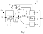
- FIG. 1 shows a schematic representation of a leak detection system and a test object in the form of a heat exchanger device.
- the illustrated exemplary embodiment shows a gas leak detector in the form of a sniffer leak detector, whose probe is a sniffer probe through whose sniffer tip the gas to be analyzed is sucked in.
- Fig. 1 shows a heat exchange device 12 in the form of a refrigerator.
- the term "heat exchange device” as used in the present disclosure refers to systems or devices that include a heat exchanger, such as refrigerators, air conditioners, heat pumps, etc.
- the heat exchange device has on its lower rear side 14 several fluid-conducting elements 16, 18 in the form of tubes, which are welded or soldered to the rear of the refrigerator during the manufacturing process.
- special test areas 20 must be identified for performing leak detection in the test areas 20.
- a test area 20 is considered to be an area of the heat exchange device in which tubes are mounted, welded or soldered together, in which a tube ends, in which a tube is connected to another tube, or in which tubes are joined together or cross each other.
- a first fluid-conducting element 16 is arranged vertically and a second fluid-conducting element 18 is connected by one of its ends to the first fluid-conducting element 16.
- the area in which the tubes 16, 18 are connected is considered as the test area 20 and is in Fig. 1 shown as a dashed circle.
- the background of the invention is the automatic movement of a sniffer probe 22 of a sniffer leak detector 24 to the test area 20 such that the sniffer tip 25 of the sniffer probe 22 is positioned close enough to aspirate gas escaping from a possible leak in one of the pipes 16, 18 within the test area 20.
- the sniffer probe 22 is connected to the gas leak detector 24 in a conventional manner via a connecting pipe or connecting capillary 26. The goal is to correlate the movement of the sniffer probe and the associated signal response of the measured signal.
- the sniffer probe 22 is mounted on the distal end 28 of a robot arm 30 of a robot 32.
- a 3D sensor 34 in the form of an imaging system 36 which has two optical cameras 38, 40 and an illumination device 42 in the form of an LED light, captures digital image data from the lower rear side 14 of the Heat exchange device 12.
- the illumination device 42 illuminates the heat exchange device 12, and in particular the lower rear side 14 of the heat exchange device 12, in a generally known manner.
- the cameras 38, 40 capture the reflected light, and the imaging system 36 generates digital image data from which a point cloud 44 is captured in a 3-dimensional virtual space 48.
- it is possible to derive the position of the measuring probe from the known position of the robot arm.
- the robot arm is guided to known measuring positions. Knowing the size and orientation of the measuring probe in relation to the robot arm, the position of the measuring probe can be determined.
- the gas detector 24 records measured values of the measurement signal of a gas stream drawn in by the sniffer tip 25, and the measurement times associated with each measured value are recorded and assigned to the measured values. Furthermore, the respective measurement positions of the sniffer tip 25 are recorded at each measurement time by recording the position of the sniffer tip, i.e., the relative position of the sniffer tip 25 with respect to the test object 12 or the measurement location 20, using the cameras 38, 40 of the 3D sensor 34.
- the measured values When evaluating the measured values, they are compared with the respective measuring positions in order to be able to determine the location of a possible leak based on the measuring positions of the respective measured values and the amplitudes of the measured values.
- a typical case of necessary signal correlation is caused by the delay in the signal response due to the transit time of the gas through the sniffer line 26. After a test gas cloud is sucked into the sniffer tip 25, the gas passes through the line 26 to the main unit of the gas detector 24.
- This transit time also called dead time, can be up to several seconds.
- the sniffer probe 22 is at the time of a signal response at the Gas detector 24, caused by an absorbed leakage gas cloud at one measuring location, may have already been moved to the next measuring location by the robot arm 30. This time delay must be taken into account when correctly assigning the measurement signal to the measuring location.
- the gas flow time must be measured beforehand. This can be done, for example, during system calibration.
- the robot arm 30 positions the tip 25 of the sniffer probe 22 in front of a test leak. The delay time between approaching the test leak and the signal response is measured. This delay time is subsequently taken into account when interpreting the signal responses at the gas detector 24 and assigning the leak locations on the test object.
Landscapes
- Physics & Mathematics (AREA)
- General Physics & Mathematics (AREA)
- Examining Or Testing Airtightness (AREA)
Applications Claiming Priority (2)
| Application Number | Priority Date | Filing Date | Title |
|---|---|---|---|
| DE102021126030.2A DE102021126030A1 (de) | 2021-10-07 | 2021-10-07 | Automatisiertes Leckdetektionsverfahren unter Verwendung eines robotischen Schnüffellecksuchers |
| PCT/EP2022/070813 WO2023057107A1 (de) | 2021-10-07 | 2022-07-25 | Automatisiertes leckdetektionsverfahren unter verwendung eines robotischen schnüffellecksuchers |
Publications (2)
| Publication Number | Publication Date |
|---|---|
| EP4413344A1 EP4413344A1 (de) | 2024-08-14 |
| EP4413344B1 true EP4413344B1 (de) | 2025-06-18 |
Family
ID=82939751
Family Applications (1)
| Application Number | Title | Priority Date | Filing Date |
|---|---|---|---|
| EP22755165.2A Active EP4413344B1 (de) | 2021-10-07 | 2022-07-25 | Automatisiertes leckdetektionsverfahren unter verwendung eines robotischen schnüffellecksuchers |
Country Status (6)
| Country | Link |
|---|---|
| US (1) | US20240288329A1 (enExample) |
| EP (1) | EP4413344B1 (enExample) |
| JP (1) | JP2024536112A (enExample) |
| CN (1) | CN117940751A (enExample) |
| DE (1) | DE102021126030A1 (enExample) |
| WO (1) | WO2023057107A1 (enExample) |
Families Citing this family (1)
| Publication number | Priority date | Publication date | Assignee | Title |
|---|---|---|---|---|
| DK181928B1 (en) * | 2023-08-14 | 2025-03-26 | Broen As | Leak test procedure and test apparatus |
Citations (1)
| Publication number | Priority date | Publication date | Assignee | Title |
|---|---|---|---|---|
| DE102018206877A1 (de) * | 2018-05-04 | 2019-11-07 | Inficon Gmbh | Verfahren zum Ermitteln der relativen Lage eines Gaslecks |
Family Cites Families (8)
| Publication number | Priority date | Publication date | Assignee | Title |
|---|---|---|---|---|
| US4945305A (en) | 1986-10-09 | 1990-07-31 | Ascension Technology Corporation | Device for quantitatively measuring the relative position and orientation of two bodies in the presence of metals utilizing direct current magnetic fields |
| DE4140725A1 (de) * | 1991-12-10 | 1993-06-17 | Jens Pohl | Verfahren und annordnung zur dichtheitspruefung von behaeltern |
| FR2870447B1 (fr) | 2004-05-21 | 2006-09-01 | Gen Electric | Dispositif de classification de pixels en mammographie a contraste accentue |
| DE102007035932A1 (de) | 2007-07-31 | 2009-02-05 | Inficon Gmbh | Lecksuchgerät |
| EP2208038A4 (en) | 2007-10-15 | 2011-12-14 | Adixen Sensistor Ab | LEAK DETECTION SYSTEM WITH A TRACER GAS DISTRIBUTION UNIT |
| DE102008047151B3 (de) * | 2008-09-12 | 2010-06-17 | Universität Kassel | Als Roboter ausgebildete Vorrichtung zur autonomen, mannlosen Ermittlung von Leckagen unter Stofffreisetzung ins Umfeld aus druckführenden Systemen, insbesondere Rohrleitungssystemen, sowie Verfahren zum Betrieb eines solchen Roboters |
| DE102012008857A1 (de) * | 2012-04-28 | 2013-10-31 | Daimler Ag | Verfahren und Prüfanlage zur Dichtheitsprüfung einer Gaseinrichtung eines Kraftwagens |
| DE102016226152B4 (de) * | 2016-12-23 | 2026-02-19 | Volkswagen Aktiengesellschaft | Verfahren zur Dichtheitsprüfung eines Behälters |
-
2021
- 2021-10-07 DE DE102021126030.2A patent/DE102021126030A1/de active Pending
-
2022
- 2022-07-25 JP JP2024519005A patent/JP2024536112A/ja active Pending
- 2022-07-25 CN CN202280060616.0A patent/CN117940751A/zh active Pending
- 2022-07-25 US US18/693,121 patent/US20240288329A1/en active Pending
- 2022-07-25 EP EP22755165.2A patent/EP4413344B1/de active Active
- 2022-07-25 WO PCT/EP2022/070813 patent/WO2023057107A1/de not_active Ceased
Patent Citations (1)
| Publication number | Priority date | Publication date | Assignee | Title |
|---|---|---|---|---|
| DE102018206877A1 (de) * | 2018-05-04 | 2019-11-07 | Inficon Gmbh | Verfahren zum Ermitteln der relativen Lage eines Gaslecks |
Also Published As
| Publication number | Publication date |
|---|---|
| DE102021126030A1 (de) | 2023-04-13 |
| EP4413344A1 (de) | 2024-08-14 |
| JP2024536112A (ja) | 2024-10-04 |
| WO2023057107A1 (de) | 2023-04-13 |
| US20240288329A1 (en) | 2024-08-29 |
| CN117940751A (zh) | 2024-04-26 |
Similar Documents
| Publication | Publication Date | Title |
|---|---|---|
| DE102016118617B4 (de) | Messsystem | |
| DE102004007828B4 (de) | Verfahren und System zur Inspektion von Oberflächen | |
| EP3140062B1 (de) | Verfahren und anordnung zum prüfen eines niets | |
| DE602005001672T2 (de) | Durchmesser Messgeräte | |
| DE69312445T2 (de) | Verfahren und Vorrichtung zur kontinuierlichen zerstörungsfreien Ultraschallprüfung von Eisenbahnschienen | |
| WO2010028949A1 (de) | Verfahren und vorrichtung zur optischen achsvermessung von kraftfahrzeugen | |
| EP3788340B1 (de) | Verfahren zum ermitteln der relativen lage eines gaslecks | |
| DE102004007830B4 (de) | Verfahren zur Lokalisierung von Fehlstellen und Markiersystem | |
| EP1711777A1 (de) | Verfahren zur bestimmung der lage eines objekts im raum | |
| EP2171416B1 (de) | Lecksuchgerät mit positionsbestimmungssystem für die handgeführte sonde | |
| EP1344051B1 (de) | Ultraschallprüfkopf, insbesondere für die prüfung per hand | |
| DE102017125033A1 (de) | Verfahren und Industrieroboter zur Prüfung von Schweißverbindungen, insbesondere von Schweißpunkten | |
| EP4413344B1 (de) | Automatisiertes leckdetektionsverfahren unter verwendung eines robotischen schnüffellecksuchers | |
| DE102008047151B3 (de) | Als Roboter ausgebildete Vorrichtung zur autonomen, mannlosen Ermittlung von Leckagen unter Stofffreisetzung ins Umfeld aus druckführenden Systemen, insbesondere Rohrleitungssystemen, sowie Verfahren zum Betrieb eines solchen Roboters | |
| DE19819066A1 (de) | Prüfverfahren zur berührungslosen Erkennung von Ungleichmäßigkeiten in der Wanddicke von unzugänglichen metallischen Rohren | |
| DE102015211025A1 (de) | Verfahren und Anordnung zur überwachten, räumlich-aufgelösten Prüfung eines dreidimensionalen Objektes | |
| EP4102204A1 (de) | Verfahren zum detektieren eines lecks in einem fluidführenden element einer wärmetauschvorrichtung | |
| DE3840998A1 (de) | Vorrichtung zum zerstoerungsfreien aufspueren von inhomogenitaeten in elastischen werkstoffen | |
| DE2613799B1 (de) | Verfahren zum Einrichten von Ultraschall-Pruefanlagen | |
| DE202021003961U1 (de) | Vorrichtung zum Detektieren eines Lecks in einem fluidführenden Element einer Wärmetauschvorrichtung | |
| DE102012202279A1 (de) | Sicherstellung einer Prüfabdeckung bei einer manuellen Inspektion | |
| DE102011089856A1 (de) | Inspektion eines Prüfobjektes | |
| DE102014106641A1 (de) | Verfahren und Vorrichtung zum automatisierten dreidimensionalen optischen Vermessen von Objekten insbesondere mit schwer zugänglichen Bereichen | |
| BE1031010B1 (de) | Verfahren zum Betreiben eines Arbeitsgeräts in einer Rohrleitung und Arbeitsgerät | |
| DE102004020242A1 (de) | Verfahren und Vorrichtung zur Leckprüfung einer Filtereinrichtung |
Legal Events
| Date | Code | Title | Description |
|---|---|---|---|
| STAA | Information on the status of an ep patent application or granted ep patent |
Free format text: STATUS: UNKNOWN |
|
| STAA | Information on the status of an ep patent application or granted ep patent |
Free format text: STATUS: THE INTERNATIONAL PUBLICATION HAS BEEN MADE |
|
| PUAI | Public reference made under article 153(3) epc to a published international application that has entered the european phase |
Free format text: ORIGINAL CODE: 0009012 |
|
| STAA | Information on the status of an ep patent application or granted ep patent |
Free format text: STATUS: REQUEST FOR EXAMINATION WAS MADE |
|
| 17P | Request for examination filed |
Effective date: 20240411 |
|
| AK | Designated contracting states |
Kind code of ref document: A1 Designated state(s): AL AT BE BG CH CY CZ DE DK EE ES FI FR GB GR HR HU IE IS IT LI LT LU LV MC MK MT NL NO PL PT RO RS SE SI SK SM TR |
|
| DAV | Request for validation of the european patent (deleted) | ||
| DAX | Request for extension of the european patent (deleted) | ||
| GRAP | Despatch of communication of intention to grant a patent |
Free format text: ORIGINAL CODE: EPIDOSNIGR1 |
|
| STAA | Information on the status of an ep patent application or granted ep patent |
Free format text: STATUS: GRANT OF PATENT IS INTENDED |
|
| INTG | Intention to grant announced |
Effective date: 20250205 |
|
| GRAS | Grant fee paid |
Free format text: ORIGINAL CODE: EPIDOSNIGR3 |
|
| GRAA | (expected) grant |
Free format text: ORIGINAL CODE: 0009210 |
|
| STAA | Information on the status of an ep patent application or granted ep patent |
Free format text: STATUS: THE PATENT HAS BEEN GRANTED |
|
| P01 | Opt-out of the competence of the unified patent court (upc) registered |
Free format text: CASE NUMBER: APP_20156/2025 Effective date: 20250428 |
|
| AK | Designated contracting states |
Kind code of ref document: B1 Designated state(s): AL AT BE BG CH CY CZ DE DK EE ES FI FR GB GR HR HU IE IS IT LI LT LU LV MC MK MT NL NO PL PT RO RS SE SI SK SM TR |
|
| REG | Reference to a national code |
Ref country code: GB Ref legal event code: FG4D Free format text: NOT ENGLISH |
|
| REG | Reference to a national code |
Ref country code: CH Ref legal event code: EP |
|
| REG | Reference to a national code |
Ref country code: DE Ref legal event code: R096 Ref document number: 502022004354 Country of ref document: DE |
|
| REG | Reference to a national code |
Ref country code: CH Ref legal event code: EP |
|
| REG | Reference to a national code |
Ref country code: IE Ref legal event code: FG4D Free format text: LANGUAGE OF EP DOCUMENT: GERMAN |
|
| PGFP | Annual fee paid to national office [announced via postgrant information from national office to epo] |
Ref country code: FR Payment date: 20250612 Year of fee payment: 4 |
|
| PG25 | Lapsed in a contracting state [announced via postgrant information from national office to epo] |
Ref country code: FI Free format text: LAPSE BECAUSE OF FAILURE TO SUBMIT A TRANSLATION OF THE DESCRIPTION OR TO PAY THE FEE WITHIN THE PRESCRIBED TIME-LIMIT Effective date: 20250618 |
|
| PGFP | Annual fee paid to national office [announced via postgrant information from national office to epo] |
Ref country code: DE Payment date: 20250617 Year of fee payment: 4 |
|
| REG | Reference to a national code |
Ref country code: LT Ref legal event code: MG9D |
|
| PG25 | Lapsed in a contracting state [announced via postgrant information from national office to epo] |
Ref country code: NO Free format text: LAPSE BECAUSE OF FAILURE TO SUBMIT A TRANSLATION OF THE DESCRIPTION OR TO PAY THE FEE WITHIN THE PRESCRIBED TIME-LIMIT Effective date: 20250918 Ref country code: GR Free format text: LAPSE BECAUSE OF FAILURE TO SUBMIT A TRANSLATION OF THE DESCRIPTION OR TO PAY THE FEE WITHIN THE PRESCRIBED TIME-LIMIT Effective date: 20250919 |
|
| PGFP | Annual fee paid to national office [announced via postgrant information from national office to epo] |
Ref country code: IT Payment date: 20250731 Year of fee payment: 4 |
|
| PG25 | Lapsed in a contracting state [announced via postgrant information from national office to epo] |
Ref country code: BG Free format text: LAPSE BECAUSE OF FAILURE TO SUBMIT A TRANSLATION OF THE DESCRIPTION OR TO PAY THE FEE WITHIN THE PRESCRIBED TIME-LIMIT Effective date: 20250618 |
|
| PG25 | Lapsed in a contracting state [announced via postgrant information from national office to epo] |
Ref country code: HR Free format text: LAPSE BECAUSE OF FAILURE TO SUBMIT A TRANSLATION OF THE DESCRIPTION OR TO PAY THE FEE WITHIN THE PRESCRIBED TIME-LIMIT Effective date: 20250618 |
|
| PGFP | Annual fee paid to national office [announced via postgrant information from national office to epo] |
Ref country code: AT Payment date: 20251020 Year of fee payment: 4 |
|
| PG25 | Lapsed in a contracting state [announced via postgrant information from national office to epo] |
Ref country code: RS Free format text: LAPSE BECAUSE OF FAILURE TO SUBMIT A TRANSLATION OF THE DESCRIPTION OR TO PAY THE FEE WITHIN THE PRESCRIBED TIME-LIMIT Effective date: 20250918 |
|
| REG | Reference to a national code |
Ref country code: NL Ref legal event code: MP Effective date: 20250618 |
|
| PG25 | Lapsed in a contracting state [announced via postgrant information from national office to epo] |
Ref country code: LV Free format text: LAPSE BECAUSE OF FAILURE TO SUBMIT A TRANSLATION OF THE DESCRIPTION OR TO PAY THE FEE WITHIN THE PRESCRIBED TIME-LIMIT Effective date: 20250618 |
|
| PG25 | Lapsed in a contracting state [announced via postgrant information from national office to epo] |
Ref country code: NL Free format text: LAPSE BECAUSE OF FAILURE TO SUBMIT A TRANSLATION OF THE DESCRIPTION OR TO PAY THE FEE WITHIN THE PRESCRIBED TIME-LIMIT Effective date: 20250618 |
|
| PG25 | Lapsed in a contracting state [announced via postgrant information from national office to epo] |
Ref country code: PT Free format text: LAPSE BECAUSE OF FAILURE TO SUBMIT A TRANSLATION OF THE DESCRIPTION OR TO PAY THE FEE WITHIN THE PRESCRIBED TIME-LIMIT Effective date: 20251020 |
|
| PG25 | Lapsed in a contracting state [announced via postgrant information from national office to epo] |
Ref country code: IS Free format text: LAPSE BECAUSE OF FAILURE TO SUBMIT A TRANSLATION OF THE DESCRIPTION OR TO PAY THE FEE WITHIN THE PRESCRIBED TIME-LIMIT Effective date: 20251018 |
|
| PG25 | Lapsed in a contracting state [announced via postgrant information from national office to epo] |
Ref country code: SM Free format text: LAPSE BECAUSE OF FAILURE TO SUBMIT A TRANSLATION OF THE DESCRIPTION OR TO PAY THE FEE WITHIN THE PRESCRIBED TIME-LIMIT Effective date: 20250618 |
|
| PG25 | Lapsed in a contracting state [announced via postgrant information from national office to epo] |
Ref country code: CZ Free format text: LAPSE BECAUSE OF FAILURE TO SUBMIT A TRANSLATION OF THE DESCRIPTION OR TO PAY THE FEE WITHIN THE PRESCRIBED TIME-LIMIT Effective date: 20250618 |
|
| PG25 | Lapsed in a contracting state [announced via postgrant information from national office to epo] |
Ref country code: PL Free format text: LAPSE BECAUSE OF FAILURE TO SUBMIT A TRANSLATION OF THE DESCRIPTION OR TO PAY THE FEE WITHIN THE PRESCRIBED TIME-LIMIT Effective date: 20250618 |
|
| PG25 | Lapsed in a contracting state [announced via postgrant information from national office to epo] |
Ref country code: EE Free format text: LAPSE BECAUSE OF FAILURE TO SUBMIT A TRANSLATION OF THE DESCRIPTION OR TO PAY THE FEE WITHIN THE PRESCRIBED TIME-LIMIT Effective date: 20250618 |
|
| PG25 | Lapsed in a contracting state [announced via postgrant information from national office to epo] |
Ref country code: SK Free format text: LAPSE BECAUSE OF FAILURE TO SUBMIT A TRANSLATION OF THE DESCRIPTION OR TO PAY THE FEE WITHIN THE PRESCRIBED TIME-LIMIT Effective date: 20250618 |
|
| PG25 | Lapsed in a contracting state [announced via postgrant information from national office to epo] |
Ref country code: ES Free format text: LAPSE BECAUSE OF FAILURE TO SUBMIT A TRANSLATION OF THE DESCRIPTION OR TO PAY THE FEE WITHIN THE PRESCRIBED TIME-LIMIT Effective date: 20250618 |
|
| REG | Reference to a national code |
Ref country code: CH Ref legal event code: H13 Free format text: ST27 STATUS EVENT CODE: U-0-0-H10-H13 (AS PROVIDED BY THE NATIONAL OFFICE) Effective date: 20260224 |
|
| PG25 | Lapsed in a contracting state [announced via postgrant information from national office to epo] |
Ref country code: LU Free format text: LAPSE BECAUSE OF NON-PAYMENT OF DUE FEES Effective date: 20250725 Ref country code: RO Free format text: LAPSE BECAUSE OF FAILURE TO SUBMIT A TRANSLATION OF THE DESCRIPTION OR TO PAY THE FEE WITHIN THE PRESCRIBED TIME-LIMIT Effective date: 20250618 |
|
| REG | Reference to a national code |
Ref country code: BE Ref legal event code: MM Effective date: 20250731 |
|
| PG25 | Lapsed in a contracting state [announced via postgrant information from national office to epo] |
Ref country code: MC Free format text: LAPSE BECAUSE OF FAILURE TO SUBMIT A TRANSLATION OF THE DESCRIPTION OR TO PAY THE FEE WITHIN THE PRESCRIBED TIME-LIMIT Effective date: 20250618 |
|
| PG25 | Lapsed in a contracting state [announced via postgrant information from national office to epo] |
Ref country code: DK Free format text: LAPSE BECAUSE OF FAILURE TO SUBMIT A TRANSLATION OF THE DESCRIPTION OR TO PAY THE FEE WITHIN THE PRESCRIBED TIME-LIMIT Effective date: 20250618 |
|
| PG25 | Lapsed in a contracting state [announced via postgrant information from national office to epo] |
Ref country code: BE Free format text: LAPSE BECAUSE OF NON-PAYMENT OF DUE FEES Effective date: 20250731 |
|
| PG25 | Lapsed in a contracting state [announced via postgrant information from national office to epo] |
Ref country code: CH Free format text: LAPSE BECAUSE OF NON-PAYMENT OF DUE FEES Effective date: 20250731 |
|
| PLBE | No opposition filed within time limit |
Free format text: ORIGINAL CODE: 0009261 |
|
| STAA | Information on the status of an ep patent application or granted ep patent |
Free format text: STATUS: NO OPPOSITION FILED WITHIN TIME LIMIT |
|
| REG | Reference to a national code |
Ref country code: CH Ref legal event code: L10 Free format text: ST27 STATUS EVENT CODE: U-0-0-L10-L00 (AS PROVIDED BY THE NATIONAL OFFICE) Effective date: 20260430 |