EP4412419A1 - Work machine for board and board manufacturing method - Google Patents
Work machine for board and board manufacturing method Download PDFInfo
- Publication number
- EP4412419A1 EP4412419A1 EP21959320.9A EP21959320A EP4412419A1 EP 4412419 A1 EP4412419 A1 EP 4412419A1 EP 21959320 A EP21959320 A EP 21959320A EP 4412419 A1 EP4412419 A1 EP 4412419A1
- Authority
- EP
- European Patent Office
- Prior art keywords
- component
- lead component
- pair
- lead
- carrier tape
- Prior art date
- Legal status (The legal status is an assumption and is not a legal conclusion. Google has not performed a legal analysis and makes no representation as to the accuracy of the status listed.)
- Pending
Links
Images





Classifications
-
- H—ELECTRICITY
- H05—ELECTRIC TECHNIQUES NOT OTHERWISE PROVIDED FOR
- H05K—PRINTED CIRCUITS; CASINGS OR CONSTRUCTIONAL DETAILS OF ELECTRIC APPARATUS; MANUFACTURE OF ASSEMBLAGES OF ELECTRICAL COMPONENTS
- H05K13/00—Apparatus or processes specially adapted for manufacturing or adjusting assemblages of electric components
- H05K13/04—Mounting of components, e.g. of leadless components
- H05K13/0404—Pick-and-place heads or apparatus, e.g. with jaws
- H05K13/0408—Incorporating a pick-up tool
-
- H—ELECTRICITY
- H05—ELECTRIC TECHNIQUES NOT OTHERWISE PROVIDED FOR
- H05K—PRINTED CIRCUITS; CASINGS OR CONSTRUCTIONAL DETAILS OF ELECTRIC APPARATUS; MANUFACTURE OF ASSEMBLAGES OF ELECTRICAL COMPONENTS
- H05K13/00—Apparatus or processes specially adapted for manufacturing or adjusting assemblages of electric components
- H05K13/08—Monitoring manufacture of assemblages
- H05K13/081—Integration of optical monitoring devices in assembly lines; Processes using optical monitoring devices specially adapted for controlling devices or machines in assembly lines
- H05K13/0812—Integration of optical monitoring devices in assembly lines; Processes using optical monitoring devices specially adapted for controlling devices or machines in assembly lines the monitoring devices being integrated in the mounting machine, e.g. for monitoring components, leads, component placement
-
- H—ELECTRICITY
- H05—ELECTRIC TECHNIQUES NOT OTHERWISE PROVIDED FOR
- H05K—PRINTED CIRCUITS; CASINGS OR CONSTRUCTIONAL DETAILS OF ELECTRIC APPARATUS; MANUFACTURE OF ASSEMBLAGES OF ELECTRICAL COMPONENTS
- H05K13/00—Apparatus or processes specially adapted for manufacturing or adjusting assemblages of electric components
- H05K13/04—Mounting of components, e.g. of leadless components
- H05K13/0417—Feeding with belts or tapes
- H05K13/0421—Feeding with belts or tapes with treatment of the terminal leads
-
- H—ELECTRICITY
- H05—ELECTRIC TECHNIQUES NOT OTHERWISE PROVIDED FOR
- H05K—PRINTED CIRCUITS; CASINGS OR CONSTRUCTIONAL DETAILS OF ELECTRIC APPARATUS; MANUFACTURE OF ASSEMBLAGES OF ELECTRICAL COMPONENTS
- H05K13/00—Apparatus or processes specially adapted for manufacturing or adjusting assemblages of electric components
- H05K13/08—Monitoring manufacture of assemblages
- H05K13/081—Integration of optical monitoring devices in assembly lines; Processes using optical monitoring devices specially adapted for controlling devices or machines in assembly lines
- H05K13/0813—Controlling of single components prior to mounting, e.g. orientation, component geometry
Definitions
- the present disclosure relates to a technique for supplying a lead component to be mounted on a board.
- Patent Literature 1 describes a board work machine in which after a lead wire of a lead component is inserted into a board, the lead wire protruding from the back surface of the board is cut and bent.
- Patent Literature 1 International Publication No. WO 2021/014635 A1
- Patent Literature 1 does not consider the supply of a lead component to the board work machine, and cannot deal with a problem that may occur when, for example, each lead component is separated and supplied from a taped lead component that is taped on a carrier tape.
- the lead component is separated from the carrier tape by cutting the lead of the taped lead component, but the lead is sometimes not cut properly and the lead component may be supplied with the carrier tape still attached.
- the carrier tape becomes an obstacle to the insertion, and the gripping claws (gripping claws 180 in Fig. 8 described later) used when the lead component is inserted into the board may be damaged.
- An object of the present disclosure is to provide a technique capable of detecting that a cutting device has failed to separate a lead component from a carrier tape before the lead component is inserted into a board.
- a board work machine of the present disclosure includes a cutting device configured to cut the lead of a taped lead component that is taped on a carrier tape to separate the lead component from the carrier tape, and a detection device configured to detect that the cutting device has failed to separate the lead component from the carrier tape.
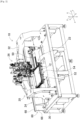
- Figs. 1 and 2 illustrate component mounter 10.
- Component mounter 10 is a device that executes mounting work of a component on circuit base material 12.
- Component mounter 10 includes device main body 20, board holding device 22, component supply device 24, component mounting device 26, and control device 28 (see Fig. 15 ).
- Examples of circuit base material 12 include a circuit board, a base material having a three-dimensional structure, and the like, and examples of the circuit board include a printed wiring board, a printed circuit board, and the like.
- Device main body 20 includes frame 30 and beam 32 suspended on frame 30.
- Board holding device 22 is disposed on the upper surface of frame 30, and includes conveyance device 50, clamp device 52, and moving device 54.
- Conveyance device 50 is a device that conveys circuit base material 12
- clamp device 52 is a device that holds circuit base material 12. Accordingly, board holding device 22 conveys circuit base material 12 by conveyance device 50, and securely holds the circuit base material 12 conveyed to a predetermined position by clamp device 52.
- the conveyance direction of circuit base material 12 is referred to as an X direction
- a horizontal direction perpendicular to that direction will be referred to as a Y direction
- a vertical direction is referred to as a Z direction.
- moving device 54 includes X-direction moving device 56 (see Fig. 15 ) and Y-direction moving device 58 (see Fig. 15 ).
- X-direction moving device 56 is a device that moves circuit base material 12 held by clamp device 52 in the X direction
- Y-direction moving device 58 is a device that moves circuit base material 12 held by clamp device 52 in the Y direction. Accordingly, circuit base material 12 held by clamp device 52 is moved to a position on the frame by X-direction moving device 56 and Y-direction moving device 58, and is positioned and stopped.
- Component supply device 24 includes sliding device 60, a tape feeder (not illustrated), and cutting device 64.
- Sliding device 60 includes holding wall 66, sliding rail 68, and feeder holding stand 70, and holding wall 66 is provided upright on the edge of the upper surface of frame 30 in the Y direction so as to extend in the X direction.
- Sliding rail 68 is fixed to holding wall 66 so as to extend in the X direction, and feeder holding stand 70 is slidably held by sliding rail 68.
- Feeder holding stand 70 slides to a position in accordance with the operation of electromagnetic motor 72 (see Fig. 15 ). Accordingly, feeder holding stand 70 slides to a position in the X direction along holding wall 66, and is positioned and stopped.
- the side on which holding wall 66 of component mounter 10 is disposed is referred to as a front side, and the opposite side is referred to as a rear side. That is, the Y direction is the front-rear direction in component mounter 10, and the X direction is the left-right direction in component mounter 10.
- multiple slots 76 are formed side by side in the X direction in feeder holding stand 70, and the tape feeder is detachably positioned and mounted in each of multiple slots 76 by one touch of an operator.
- the tape feeder is a device that feeds taped component 78 (see Fig. 3 ) toward cutting device 64.
- Taped component 78 includes multiple radial lead components 80 and carrier tape 82, as illustrated in Fig. 3 .
- Radial lead component 80 includes substantially cylindrical main body 86 and two leads 88 extending in the same direction from the lower surface of main body 86. Two leads 88 of radial lead component 80 are taped to carrier tape 82 at the lower end portions thereof.
- multiple feeding holes 90 are formed at a uniform pitch in carrier tape 82. Multiple radial lead components 80 are taped to carrier tape 82 at the same pitch as the formation pitch of feeding holes 90.
- storage container 92 is disposed below feeder holding stand 70 on which the tape feeder is mounted, and taped component 78 is stored in a folded state in storage container 92.
- taped component 78 is pulled out from storage container 92, and the one end is inserted into the tape feeder.
- cutting device 64 is a device that separates radial lead component 80 from taped component 78 by cutting leads 88 taped to taped component 78 fed from the tape feeder, and is attached and fixed to the lower surface side of beam 32 as illustrated in Fig. 1 .
- plate-shaped bracket 110 illustrated in Fig. 3 is fixed to the lower surface of beam 32 in a position extending downward.
- cutting device 64 has a pair of substantially block-shaped sliders 112, and the pair of sliders 112 are held by bracket 110 on the front side of bracket 110 so as to move toward and away from each other in the X direction.
- the pair of sliders 112 are controllably moved toward and away from each other by the operation of air cylinder 114 (see Fig. 15 ).
- each of the pair of sliders 112 is substantially a horizontal surface
- the front surface of each of the pair of sliders 112 is substantially a vertical surface.
- a pair of lead cutters 116 are fixed to the upper surfaces of the pair of sliders 112 with the cutting edges facing each other.
- the pair of lead cutters 116 are fixed to the upper surfaces of the pair of sliders 112 with the cutting edges protruding from the ends of sliders 112 in the X direction.
- a pair of tape cutters 118 are fixed to the front surfaces of the pair of sliders 112 with the cutting edges facing each other.
- the pair of tape cutters 118 are fixed to the front surfaces of the pair of sliders 112 with the cutting edges protruding from the ends of sliders 112 in the X direction.
- Lead 88 taped on carrier tape 82 extends upward from the gap between the pair of sliders 112 and is inserted between the pair of lead cutters 116 fixed to the upper surfaces of the pair of sliders 112.
- the pair of sliders 112 are brought closer to the operation of air cylinder 114, whereby the pair of leads 88 are cut by the pair of lead cutters 116.
- one radial lead component 80 is separated from taped component 78 in cutting device 64.
- component mounting device 26 is a device for mounting radial lead component 80 separated from taped component 78 by cutting device 64 on circuit base material 12, and is disposed on beam 32 as illustrated in Figs. 1 and 2 .
- component mounting device 26 is disposed on a surface of bracket 110 on a side opposite to cutting device 64 where cutting device 64 is disposed. That is, cutting device 64 is disposed on the front side surface of bracket 110, and component mounting device 26 is disposed on the rear side surface of bracket 110.
- Fig. 4 is a view illustrating a rear side surface of bracket 110
- Fig. 5 is a view illustrating a front side surface of bracket 110.
- Component mounting device 26 includes three chucks of first chuck 140, second chuck 142, and third chuck 144.
- First chuck 140 grips radial lead component 80 separated from taped component 78 by cutting device 64
- second chuck 142 grips radial lead component 80 transferred from first chuck 140
- third chuck 144 grips radial lead component 80 transferred from second chuck 142 to mount radial lead component 80 on circuit base material 12.
- first chuck 140 includes a pair of gripping claws 150 and spline shaft 152.
- Spline shaft 152 is disposed on the rear side of the pair of sliders 112 so as to extend in the X direction, and is held by bracket 110 so as to be rotatable about the axis.
- the pair of gripping claws 150 are held by spline shaft 152 so as to move toward and away from each other in the X direction, and the respective positions are controllably moved toward and away from each other by the operation of electromagnetic motor 154 (see Fig. 15 ).
- spline shaft 152 is controllably rotated by the operation of electromagnetic motor 156 (see Fig. 15 ), and the pair of gripping claws 150 held by spline shaft 152 rotate 90° in the front-rear direction.
- a pair of sensor brackets 120 are fixed to bracket 110 in a position extending downward.
- Each of sensor brackets 120 has a quadrangular prism shape, and each of sensor brackets 120 is fixed in a state in which one of four surfaces constituting a peripheral wall thereof faces each other.
- Component detection sensor 122 and bad lead cut detection sensor 124 are provided on each of the opposing surfaces of each sensor bracket 120.
- transmissive optical sensors are used for both sensors 122 and 124. Accordingly, light emitting parts of both sensors 122 and 124 are provided on one opposing surface of a first one of sensor brackets 120, and light receiving parts of both sensors 122 and 124 are provided on one opposing surface of a second one of sensor brackets 120.
- component detection sensor 122 detects whether the pair of leads 88 of radial lead component 80 to be separated is inserted between the pair of lead cutters 116.
- control device 28 checks the output from component detection sensor 122 at the timing when one radial lead component 80 is fed out from the tape feeder to cutting device 64, and determines that radial lead component 80 to be separated is at an appropriate cutting position when a decrease in the output is detected.
- Component detection sensor 122 is installed at a position where the optical axis is blocked by, for example, one lead 88 of the pair of leads 88 of radial lead component 80 when radial lead component 80 to be separated is at an appropriate cutting position.
- the installation position of component detection sensor 122 is not limited thereto as long as it is possible to detect that radial lead component 80 to be separated is at an appropriate cutting position.
- Bad lead cut detection sensor 124 detects that cutting device 64 has failed to cut the pair of leads 88 of radial lead component 80 to be separated and a part of carrier tape 82 remains attached to leads 88.
- control device 28 checks the output from bad lead cut detection sensor 124 at a predetermined timing while radial lead component 80 after the cutting operation by cutting device 64 is gripped by the pair of gripping claws 150, the pair of gripping claws 150 are rotated rearward, and radial lead component 80 gripped by the pair of gripping claws 150 reaches a position where radial lead component 80 can be delivered to second chuck 142.
- control device 28 determines that a part of carrier tape 82 remains attached to leads 88, that is, cutting device 64 has failed to cut the pair of leads 88 of radial lead component 80 to be separated.
- the predetermined timing is a timing at which bad lead cut detection sensor 124 can detect a part of carrier tape 82 remaining attached to the pair of leads 88 of radial lead component 80 in the middle of being conveyed by the pair of gripping claws 150, that is, a timing at which the pair of gripping claws 150 are in a predetermined range of rotation.
- bad lead cut detection sensor 124 is installed at a position where a part of carrier tape 82 remaining attached to the pair of leads 88 of radial lead component 80 can be detected when the pair of gripping claws 150 are in the predetermined range of rotation.
- second chuck 142 includes a pair of gripping claws 160, placement plate 162, and bracket 164.
- Fig. 8 is a view illustrating second chuck 142 viewed from the front side.
- the pair of gripping claws 160 are held by bracket 164 so as to move toward and away from each other in the X direction, and the respective positions are controllably moved toward and away by the operation of electromagnetic motor 166 (see Fig. 15 ).
- placement plate 162 is fixedly held by bracket 164 between the pair of gripping claws 160.
- Placement plate 162 is curved in an arc shape according to cylindrical main body 86 of radial lead component 80.
- bracket 164 is sandwiched between a pair of support walls 170 (only one of the pair of support walls 170 is illustrated in Fig. 8 ) on both side surfaces in the X direction.
- a pair of cam grooves 172 are formed in the pair of support walls 170, and a pair of rollers 174 having an axis in the X direction are disposed on both side surfaces of bracket 164 in the X direction.
- bracket 164 is held by the pair of support walls 170.
- the shape of cam groove 172 is substantially an arc shape, is curved upward toward the rear, and is curved downward toward the front. As illustrated in Fig.
- bracket 164 is moved down with respect to support wall 170, and roller 174 is moved toward the lower end of cam groove 172, whereby the pair of gripping claws 160 and placement plate 162 are in a position extending in the vertical direction. At this time, the distal ends of the pair of gripping claws 160 face downward. Meanwhile, as illustrated in Fig. 6 , bracket 164 is moved up with respect to support wall 170, and roller 174 moves toward the upper end of cam groove 172, whereby the pair of gripping claws 160 and placement plate 162 are in a position extending in the front-rear direction. At this time, the distal ends of the pair of gripping claws 160 face forward. Bracket 164 is controllably moved up and down with respect to support wall 170 by the operation of electromagnetic motor 178 ( Fig. 15 ).
- bracket 164 when bracket 164 is moved up with respect to support wall 170 and the pair of gripping claws 160 and placement plate 162 of second chuck 142 are in a position extending in the front-rear direction, placement plate 162 is positioned behind radial lead component 80 gripped by the pair of gripping claws 150 of first chuck 140. At this time, the pair of gripping claws 160 of second chuck 142 are separated from each other. Therefore, when the pair of gripping claws 150 of first chuck 140 are rotated rearward, main body 86 of radial lead component 80 gripped by the pair of gripping claws 150 is placed on placement plate 162.
- third chuck 144 is disposed below the pair of support walls 170 and includes a pair of gripping claws 180.
- Hanging member 182 is fixed to the rear side of the pair of support walls 170, and hanging member 182 extends downward from the lower ends of the pair of support walls 170.
- the pair of gripping claws 180 are disposed at the lower end of hanging member 182 so as to move toward and away from each other, and the pair of gripping claws 180 extend forward. That is, the pair of gripping claws 180 of third chuck 144 are disposed on the pair of support walls 170 via hanging member 182 and extend downward from the pair of support walls 170.
- the pair of gripping claws 180 are controllably moved toward and away from each other by the operation of electromagnetic motor 186 (see Fig. 15 ).
- bracket 164 held by the pair of support walls 170 is moved down with respect to support walls 170, the distal ends of the pair of gripping claws 160 of second chuck 142 held by bracket 164 face downward as described above.
- the distal ends of the pair of leads 88 of radial lead component 80 gripped by gripping claws 160 of second chuck 142 also face downward.
- bracket 164 moves down the pair of gripping claws 180 of third chuck 144 are separated from each other. Then, the pair of leads 88 whose distal ends face downward are inserted between the pair of gripping claws 180 of third chuck 144.
- the pair of support walls 170 on which the pair of gripping claws 180 of third chuck 144 are disposed are fixed to flange 188 at the upper end.
- Flange 188 is controllably moved up and down by the operation of electromagnetic motor 190 (see Fig. 15 ). Accordingly, the position of radial lead component 80 gripped by the pair of gripping claws 180 of third chuck 144 in the vertical direction can be changed freely.
- Flange 188 is controllably rotated on the XY plane by the operation of electromagnetic motor 192 (see Fig. 15 ).
- pusher 196 is disposed above radial lead component 80 gripped by third chuck 144.
- Pusher 196 is held by bracket 164 so as to move up and down, and is controllably moved up and down by the operation of electromagnetic motor 198 (see Fig. 15 ).
- electromagnetic motor 198 see Fig. 15 .
- control device 28 includes controller 200 and multiple drive circuits 202.
- Multiple drive circuits 202 are connected to conveyance device 50, clamp device 52, X-direction moving device 56, Y-direction moving device 58, air cylinder 114, and electromagnetic motors 72, 154, 156, 166, 178, 186, 190, 192, and 198.
- Controller 200 includes CPU, ROM, RAM, and the like, is mainly a computer, and is connected to multiple drive circuits 202. Controller 200 is also connected to component detection sensor 122 and bad lead cut detection sensor 124. Accordingly, operations of board holding device 22, component supply device 24, and component mounting device 26 are controlled by controller 200.
- Fig. 10 illustrates a state before taped component 78 is conveyed to cutting device 64. At this time, light is emitted from each light emitting part of component detection sensor 122 and bad lead cut detection sensor 124. That is, component detection sensor 122 and bad lead cut detection sensor 124 are always in the ON state during the operation of component mounter 10 before or after taped component 78 is conveyed to cutting device 64.
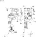
- Fig. 11 illustrates a state in which one radial lead component 80 is normally cut from taped component 78, the pair of leads 88 of radial lead component 80 to which part of carrier tape 82 is not attached are being conveyed to the delivery position of second chuck 142 by the pair of gripping claws 150.
- the optical axis of bad lead cut detection sensor 124 is not blocked, and a decrease in the output is not detected from bad lead cut detection sensor 124.
- control device 28 determines that the pair of leads 88 of radial lead component 80 in the middle of being conveyed have been cut more properly by cutting device 64, and performs normal insertion control of radial lead component 80 into circuit base material 12.
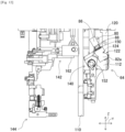
- Fig. 12 illustrates a state in which part 82a of carrier tape 82 is attached to the pair of leads 88 of radial lead component 80 although the conveyance timing of radial lead component 80 is the same as that in Fig. 11 .
- control device 28 determines that the pair of leads 88 of radial lead component 80 in the middle of being conveyed are not cut by cutting device 64 more properly, and stops the operation of component mounter 10. Then, control device 28 executes a component discarding command for radial lead component 80 in the middle of being conveyed.
- Figs. 13 and 14 illustrate a state in which radial lead component 80 in the middle of being conveyed is conveyed to a takeout position by executing a component discarding command.
- radial lead component 80 in which part 82a of carrier tape 82 is attached to the pair of leads 88 is referred to as radial lead component 80 having a bad lead cut.
- radial lead component 80 having a bad lead cut is delivered from first chuck 140 to second chuck 142, similarly to radial lead component 80 having no bad lead cut. Then, radial lead component 80 having a bad lead cut gripped by second chuck 142 is moved down toward the delivery position of third chuck 144 as described above.
- radial lead component 80 having a bad lead cut gripped by second chuck 142 stops before extending in the vertical direction, and flange 188 is rotated by 180° by electromagnetic motor 192. Accordingly, as illustrated in Fig. 14 , radial lead component 80 having a bad lead cut gripped by second chuck 142 is conveyed to a position where radial lead component 80 is easily taken out by the operator.
- radial lead component 80 it is determined whether radial lead component 80 has a bad lead cut before radial lead component 80 is delivered from first chuck 140 to second chuck 142.
- control device 28 immediately stops the operation of component mounter 10. That is, as illustrated in Fig. 12 , radial lead component 80 having a bad lead cut is stopped in the middle of being conveyed by first chuck 140, and the subsequent conveyance to a position where the operator can easily take out radial lead component 80 is performed by control device 28 executing a component discarding command.
- control device 28 may stop the operation of component mounter 10 after first chuck 140 delivers radial lead component 80 having a bad lead cut to second chuck 142 when it is determined that radial lead component 80 has a bad lead cut.
- an operation in which second chuck 142 receives radial lead component 80 having a bad lead cut and then conveys radial lead component 80 to a position where the operator can easily take out radial lead component 80 is performed by control device 28 executing a component discarding command.
- radial lead component 80 when it is determined that radial lead component 80 has a bad lead cut, the operation of entire component mounter 10 is stopped, but the operation is not limited thereto, and the operation of a part of component mounter 10, for example, component supply device 24 and component mounting device 26, may be stopped.
- second chuck 142 when a component discarding command is executed, second chuck 142 receives and grips radial lead component 80 having a bad lead cut from first chuck 140, and conveys gripped radial lead component 80 having a bad lead cut to a position where the operator can easily take out radial lead component 80.
- the 180° rotation operation of flange 188 by electromagnetic motor 192 is performed after radial lead component 80 having a bad lead cut is moved down toward the delivery position of third chuck 144 and stopped before extending in the vertical direction.
- the present invention is not limited thereto, and the 180° rotation operation of flange 188 by electromagnetic motor 192 may be performed immediately from a state in which second chuck 142 receives and grips radial lead component 80 having a bad lead cut from first chuck 140 (see Fig. 13 ).
- the operation of moving radial lead component 80 having a bad lead cut down toward the delivery position of third chuck 144 is performed after the 180° rotation operation of flange 188.
- the rotation operation of flange 188 and the moving-down operation of radial lead component 80 having a bad lead cut may be performed in parallel.
- a component discarding command is executed at the same time as component mounter 10 is stopped
- the present invention is not limited thereto, and it is also possible to only stop component mounter 10 and not execute the component discarding command. In this case, whether to execute the component discarding command need only be left to the operator's selection.
- component mounter 10 of the present embodiment includes cutting device 64 that cuts leads 88 of taped component 78 in which radial lead component 80 is taped on carrier tape 82 to separate radial lead component 80 from carrier tape 82, and bad lead cut detection sensor 124 that detects that cutting device 64 has failed to separate radial lead component 80 from carrier tape 82.
- component mounter 10 of the present embodiment since bad lead cut detection sensor 124 detects that cutting device 64 has failed to separate radial lead component 80 from carrier tape 82, failure of cutting device 64 to separate radial lead component 80 from carrier tape 82 can be detected before radial lead component 80 is inserted into circuit base material 12.
- component mounter 10 is an example of a "board work machine”.
- Radial lead component 80 is an example of a "lead component”.
- Taped component 78 is an example of a "taped lead component”.
- Bad lead cut detection sensor 124 is an example of a "detection device”.
- bad lead cut detection sensor 124 detects that cutting device 64 has failed to separate radial lead component from carrier tape 82 by detecting that carrier tape 82 remains uncut on radial lead component 80 after the cutting operation by cutting device 64.
- Further bad lead cut detection sensor 124 detects that carrier tape 82 remains uncut on radial lead component 80 while radial lead component 80 after the cutting operation by cutting device 64 is conveyed to a predetermined conveyance position.
- Component mounter 10 further includes control device 28 that causes the conveyance of radial lead component 80 to stop when bad lead cut detection sensor 124 detects that cutting device 64 has failed to separate radial lead component from carrier tape 82. This makes it possible to prevent the device from being damaged due to radial lead component 80 having a bad lead cut.
- control device 28 performs control such that radial lead component 80 is conveyed to a predetermined takeout position, after stopping the conveyance of radial lead component 80. Accordingly, the operator can easily take out radial lead component 80 having a bad lead cut.
- Component mounter 10 further includes component detection sensor 122 that detects whether taped component 78 is conveyed to a position where cutting device 64 performs a cutting operation.
- component detection sensor 122 detects that cutting device 64 has failed to separate radial lead component 80 from carrier tape 82 when component detection sensor 122 detects that taped component 78 has been conveyed to the position where cutting device 64 performs the cutting operation.
- component detection sensor 122 is an example of a "component detection device”.
- component mounter 10: component mounter, 28: control device, 64: cutting device, 78: taped component, 80: radial lead component, 82: carrier tape, 122: component detection sensor, 124: bad lead cut detection sensor
Landscapes
- Engineering & Computer Science (AREA)
- Manufacturing & Machinery (AREA)
- Microelectronics & Electronic Packaging (AREA)
- Operations Research (AREA)
- Supply And Installment Of Electrical Components (AREA)
Abstract
Description
- The present disclosure relates to a technique for supplying a lead component to be mounted on a board.
- Patent Literature 1 describes a board work machine in which after a lead wire of a lead component is inserted into a board, the lead wire protruding from the back surface of the board is cut and bent.
- Patent Literature 1: International Publication No.
WO 2021/014635 A1 - However, the board work machine described in Patent Literature 1 does not consider the supply of a lead component to the board work machine, and cannot deal with a problem that may occur when, for example, each lead component is separated and supplied from a taped lead component that is taped on a carrier tape.
- Specifically, in this case, the lead component is separated from the carrier tape by cutting the lead of the taped lead component, but the lead is sometimes not cut properly and the lead component may be supplied with the carrier tape still attached. When the lead component supplied with the carrier tape attached thereto is inserted into a board in this manner, the carrier tape becomes an obstacle to the insertion, and the gripping claws (gripping
claws 180 inFig. 8 described later) used when the lead component is inserted into the board may be damaged. - An object of the present disclosure is to provide a technique capable of detecting that a cutting device has failed to separate a lead component from a carrier tape before the lead component is inserted into a board.
- In order to achieve the above object, a board work machine of the present disclosure includes a cutting device configured to cut the lead of a taped lead component that is taped on a carrier tape to separate the lead component from the carrier tape, and a detection device configured to detect that the cutting device has failed to separate the lead component from the carrier tape.
- According to the present disclosure, it is possible to detect that a cutting device has failed to separate a lead component from a carrier tape before the lead component is inserted into a board.
-
-
Fig. 1 is a perspective view illustrating a component mounter. -
Fig. 2 is a perspective view illustrating the component mounter. -
Fig. 3 is a perspective view illustrating a cutting device. -
Fig. 4 is a perspective view illustrating a component mounting device. -
Fig. 5 is a perspective view illustrating the component mounting device. -
Fig. 6 is a perspective view illustrating the cutting device and the component mounting device. -
Fig. 7 is a cross-sectional view taken along the line B-B ofFig. 6 . -
Fig. 8 is a perspective view illustrating a second chuck and a third chuck. -
Fig. 9 is a perspective view illustrating the component mounting device. -
Fig. 10 is a side view illustrating the cutting device and the component mounting device. -
Fig. 11 is a side view illustrating a state in which the component mounting device conveys a radial lead component having a good lead cut. -
Fig. 12 is a side view illustrating a state in which the component mounting device conveys a radial lead component having a bad lead cut. -
Fig. 13 is a side view illustrating a state in which the component mounting device clamps a radial lead component having a bad lead cut. -
Fig. 14 is a side view illustrating a state in which the component mounting device conveys a radial lead component having a bad lead cut to a takeout position. -
Fig. 15 is a block view illustrating a control device of the component mounter. - Embodiments of the present disclosure will be described in detail below with reference to the accompanying drawings.
-
Figs. 1 and2 illustrate component mounter 10.Component mounter 10 is a device that executes mounting work of a component oncircuit base material 12.Component mounter 10 includes devicemain body 20,board holding device 22,component supply device 24,component mounting device 26, and control device 28 (seeFig. 15 ). Examples ofcircuit base material 12 include a circuit board, a base material having a three-dimensional structure, and the like, and examples of the circuit board include a printed wiring board, a printed circuit board, and the like. - Device
main body 20 includesframe 30 andbeam 32 suspended onframe 30.Board holding device 22 is disposed on the upper surface offrame 30, and includesconveyance device 50,clamp device 52, and movingdevice 54.Conveyance device 50 is a device that conveyscircuit base material 12, andclamp device 52 is a device that holdscircuit base material 12. Accordingly,board holding device 22 conveyscircuit base material 12 byconveyance device 50, and securely holds thecircuit base material 12 conveyed to a predetermined position byclamp device 52. The conveyance direction ofcircuit base material 12 is referred to as an X direction, a horizontal direction perpendicular to that direction will be referred to as a Y direction, and a vertical direction is referred to as a Z direction. Further, movingdevice 54 includes X-direction moving device 56 (seeFig. 15 ) and Y-direction moving device 58 (seeFig. 15 ).X-direction moving device 56 is a device that movescircuit base material 12 held byclamp device 52 in the X direction, and Y-direction moving device 58 is a device that movescircuit base material 12 held byclamp device 52 in the Y direction. Accordingly,circuit base material 12 held byclamp device 52 is moved to a position on the frame byX-direction moving device 56 and Y-direction moving device 58, and is positioned and stopped. -
Component supply device 24 includessliding device 60, a tape feeder (not illustrated), andcutting device 64.Sliding device 60 includesholding wall 66, slidingrail 68, andfeeder holding stand 70, andholding wall 66 is provided upright on the edge of the upper surface offrame 30 in the Y direction so as to extend in the X direction. Slidingrail 68 is fixed to holdingwall 66 so as to extend in the X direction, andfeeder holding stand 70 is slidably held by slidingrail 68. Feeder holding stand 70 slides to a position in accordance with the operation of electromagnetic motor 72 (seeFig. 15 ). Accordingly, feeder holding stand 70 slides to a position in the X direction along holdingwall 66, and is positioned and stopped. The side on which holdingwall 66 ofcomponent mounter 10 is disposed is referred to as a front side, and the opposite side is referred to as a rear side. That is, the Y direction is the front-rear direction incomponent mounter 10, and the X direction is the left-right direction incomponent mounter 10. - Further,
multiple slots 76 are formed side by side in the X direction infeeder holding stand 70, and the tape feeder is detachably positioned and mounted in each ofmultiple slots 76 by one touch of an operator. The tape feeder is a device that feeds taped component 78 (seeFig. 3 ) towardcutting device 64. Tapedcomponent 78 includes multipleradial lead components 80 andcarrier tape 82, as illustrated inFig. 3 .Radial lead component 80 includes substantially cylindricalmain body 86 and two leads 88 extending in the same direction from the lower surface ofmain body 86. Twoleads 88 ofradial lead component 80 are taped tocarrier tape 82 at the lower end portions thereof. Further,multiple feeding holes 90 are formed at a uniform pitch incarrier tape 82. Multipleradial lead components 80 are taped tocarrier tape 82 at the same pitch as the formation pitch offeeding holes 90. - As illustrated in
Fig. 1 ,storage container 92 is disposed belowfeeder holding stand 70 on which the tape feeder is mounted, and tapedcomponent 78 is stored in a folded state instorage container 92. One end of tapedcomponent 78 is pulled out fromstorage container 92, and the one end is inserted into the tape feeder. - Further,
cutting device 64 is a device that separatesradial lead component 80 from tapedcomponent 78 by cutting leads 88 taped to tapedcomponent 78 fed from the tape feeder, and is attached and fixed to the lower surface side ofbeam 32 as illustrated inFig. 1 . Specifically, plate-shaped bracket 110 illustrated inFig. 3 is fixed to the lower surface ofbeam 32 in a position extending downward. Further,cutting device 64 has a pair of substantially block-shaped sliders 112, and the pair ofsliders 112 are held bybracket 110 on the front side ofbracket 110 so as to move toward and away from each other in the X direction. The pair ofsliders 112 are controllably moved toward and away from each other by the operation of air cylinder 114 (seeFig. 15 ). - The upper surface of each of the pair of
sliders 112 is substantially a horizontal surface, and the front surface of each of the pair ofsliders 112 is substantially a vertical surface. A pair oflead cutters 116 are fixed to the upper surfaces of the pair ofsliders 112 with the cutting edges facing each other. The pair oflead cutters 116 are fixed to the upper surfaces of the pair ofsliders 112 with the cutting edges protruding from the ends ofsliders 112 in the X direction. Further, a pair oftape cutters 118 are fixed to the front surfaces of the pair ofsliders 112 with the cutting edges facing each other. The pair oftape cutters 118 are fixed to the front surfaces of the pair ofsliders 112 with the cutting edges protruding from the ends ofsliders 112 in the X direction. -
Lead 88 taped oncarrier tape 82 extends upward from the gap between the pair ofsliders 112 and is inserted between the pair oflead cutters 116 fixed to the upper surfaces of the pair ofsliders 112. In a state where a pair ofleads 88 of oneradial lead component 80 are inserted between the pair oflead cutters 116, the pair ofsliders 112 are brought closer to the operation ofair cylinder 114, whereby the pair ofleads 88 are cut by the pair oflead cutters 116. Thus, oneradial lead component 80 is separated from tapedcomponent 78 in cuttingdevice 64. - Further,
component mounting device 26 is a device for mountingradial lead component 80 separated from tapedcomponent 78 by cuttingdevice 64 oncircuit base material 12, and is disposed onbeam 32 as illustrated inFigs. 1 and2 . Specifically, as illustrated inFigs. 4 and5 ,component mounting device 26 is disposed on a surface ofbracket 110 on a side opposite to cuttingdevice 64 where cuttingdevice 64 is disposed. That is, cuttingdevice 64 is disposed on the front side surface ofbracket 110, andcomponent mounting device 26 is disposed on the rear side surface ofbracket 110.Fig. 4 is a view illustrating a rear side surface ofbracket 110, andFig. 5 is a view illustrating a front side surface ofbracket 110. -
Component mounting device 26 includes three chucks offirst chuck 140,second chuck 142, andthird chuck 144.First chuck 140 gripsradial lead component 80 separated from tapedcomponent 78 by cuttingdevice 64,second chuck 142 gripsradial lead component 80 transferred fromfirst chuck 140, andthird chuck 144 gripsradial lead component 80 transferred fromsecond chuck 142 to mountradial lead component 80 oncircuit base material 12. - As illustrated in
Fig. 6 andFig. 7 which is a cross-sectional view taken along the line B-B ofFig. 6 ,first chuck 140 includes a pair ofgripping claws 150 andspline shaft 152.Spline shaft 152 is disposed on the rear side of the pair ofsliders 112 so as to extend in the X direction, and is held bybracket 110 so as to be rotatable about the axis. The pair ofgripping claws 150 are held byspline shaft 152 so as to move toward and away from each other in the X direction, and the respective positions are controllably moved toward and away from each other by the operation of electromagnetic motor 154 (seeFig. 15 ). Further,spline shaft 152 is controllably rotated by the operation of electromagnetic motor 156 (seeFig. 15 ), and the pair ofgripping claws 150 held byspline shaft 152 rotate 90° in the front-rear direction. - When the pair of
gripping claws 150 are rotated forward, grippingclaws 150 are positioned above the pair oflead cutters 116 as illustrated inFig. 6 . Therefore, when the pair ofgripping claws 150 are rotated forward by the operation ofelectromagnetic motor 156 and move toward each other by the operation ofelectromagnetic motor 154, leads 88 ofradial lead component 80 separated from tapedcomponent 78 can be gripped by the pair ofgripping claws 150. When the pair ofgripping claws 150 are rotated rearward, the pair ofgripping claws 150 are rotated to a position whereradial lead component 80 gripped by the pair ofgripping claws 150 can be delivered tosecond chuck 142. - As illustrated in
Fig. 6 , a pair ofsensor brackets 120 are fixed tobracket 110 in a position extending downward. Each ofsensor brackets 120 has a quadrangular prism shape, and each ofsensor brackets 120 is fixed in a state in which one of four surfaces constituting a peripheral wall thereof faces each other.Component detection sensor 122 and bad leadcut detection sensor 124 are provided on each of the opposing surfaces of eachsensor bracket 120. In the present embodiment, transmissive optical sensors are used for bothsensors sensors sensor brackets 120, and light receiving parts of bothsensors sensor brackets 120. - When cutting
device 64 performs an operation of separating oneradial lead component 80 from tapedcomponent 78,component detection sensor 122 detects whether the pair ofleads 88 ofradial lead component 80 to be separated is inserted between the pair oflead cutters 116. Specifically, control device 28 (seeFig. 15 ) checks the output fromcomponent detection sensor 122 at the timing when oneradial lead component 80 is fed out from the tape feeder to cuttingdevice 64, and determines thatradial lead component 80 to be separated is at an appropriate cutting position when a decrease in the output is detected.Component detection sensor 122 is installed at a position where the optical axis is blocked by, for example, onelead 88 of the pair ofleads 88 ofradial lead component 80 whenradial lead component 80 to be separated is at an appropriate cutting position. Of course, the installation position ofcomponent detection sensor 122 is not limited thereto as long as it is possible to detect thatradial lead component 80 to be separated is at an appropriate cutting position. - Bad lead cut
detection sensor 124 detects that cuttingdevice 64 has failed to cut the pair ofleads 88 ofradial lead component 80 to be separated and a part ofcarrier tape 82 remains attached to leads 88. Specifically, control device 28 (seeFig. 15 ) checks the output from bad leadcut detection sensor 124 at a predetermined timing whileradial lead component 80 after the cutting operation by cuttingdevice 64 is gripped by the pair ofgripping claws 150, the pair ofgripping claws 150 are rotated rearward, andradial lead component 80 gripped by the pair ofgripping claws 150 reaches a position whereradial lead component 80 can be delivered tosecond chuck 142. When a decrease in the output is detected from bad leadcut detection sensor 124,control device 28 determines that a part ofcarrier tape 82 remains attached to leads 88, that is, cuttingdevice 64 has failed to cut the pair ofleads 88 ofradial lead component 80 to be separated. The predetermined timing is a timing at which bad leadcut detection sensor 124 can detect a part ofcarrier tape 82 remaining attached to the pair ofleads 88 ofradial lead component 80 in the middle of being conveyed by the pair ofgripping claws 150, that is, a timing at which the pair ofgripping claws 150 are in a predetermined range of rotation. Conversely, bad leadcut detection sensor 124 is installed at a position where a part ofcarrier tape 82 remaining attached to the pair ofleads 88 ofradial lead component 80 can be detected when the pair ofgripping claws 150 are in the predetermined range of rotation. - As illustrated in
Figs. 7 and8 ,second chuck 142 includes a pair ofgripping claws 160,placement plate 162, andbracket 164.Fig. 8 is a view illustratingsecond chuck 142 viewed from the front side. The pair ofgripping claws 160 are held bybracket 164 so as to move toward and away from each other in the X direction, and the respective positions are controllably moved toward and away by the operation of electromagnetic motor 166 (seeFig. 15 ). Further,placement plate 162 is fixedly held bybracket 164 between the pair ofgripping claws 160.Placement plate 162 is curved in an arc shape according to cylindricalmain body 86 ofradial lead component 80. - Further,
bracket 164 is sandwiched between a pair of support walls 170 (only one of the pair ofsupport walls 170 is illustrated inFig. 8 ) on both side surfaces in the X direction. A pair ofcam grooves 172 are formed in the pair ofsupport walls 170, and a pair ofrollers 174 having an axis in the X direction are disposed on both side surfaces ofbracket 164 in the X direction. When the pair ofrollers 174 are fitted into the pair ofcam grooves 172,bracket 164 is held by the pair ofsupport walls 170. The shape ofcam groove 172 is substantially an arc shape, is curved upward toward the rear, and is curved downward toward the front. As illustrated inFig. 8 ,bracket 164 is moved down with respect to supportwall 170, androller 174 is moved toward the lower end ofcam groove 172, whereby the pair ofgripping claws 160 andplacement plate 162 are in a position extending in the vertical direction. At this time, the distal ends of the pair ofgripping claws 160 face downward. Meanwhile, as illustrated inFig. 6 ,bracket 164 is moved up with respect to supportwall 170, androller 174 moves toward the upper end ofcam groove 172, whereby the pair ofgripping claws 160 andplacement plate 162 are in a position extending in the front-rear direction. At this time, the distal ends of the pair ofgripping claws 160 face forward.Bracket 164 is controllably moved up and down with respect to supportwall 170 by the operation of electromagnetic motor 178 (Fig. 15 ). - In addition, when
bracket 164 is moved up with respect to supportwall 170 and the pair ofgripping claws 160 andplacement plate 162 ofsecond chuck 142 are in a position extending in the front-rear direction,placement plate 162 is positioned behindradial lead component 80 gripped by the pair ofgripping claws 150 offirst chuck 140. At this time, the pair ofgripping claws 160 ofsecond chuck 142 are separated from each other. Therefore, when the pair ofgripping claws 150 offirst chuck 140 are rotated rearward,main body 86 ofradial lead component 80 gripped by the pair ofgripping claws 150 is placed onplacement plate 162. Whenmain body 86 ofradial lead component 80 is placed onplacement plate 162, the pair ofgripping claws 160 ofsecond chuck 142 move toward each other, wherebymain body 86 ofradial lead component 80 placed onplacement plate 162 is gripped by the pair ofgripping claws 160. Further, aftermain body 86 ofradial lead component 80 is placed onplacement plate 162, the pair ofgripping claws 150 are separated from each other, whereby the gripping ofradial lead component 80 byfirst chuck 140 is released. Thus,radial lead component 80 gripped byfirst chuck 140 is transferred tosecond chuck 142 and gripped bysecond chuck 142. - As illustrated in
Fig. 9 ,third chuck 144 is disposed below the pair ofsupport walls 170 and includes a pair ofgripping claws 180. Hangingmember 182 is fixed to the rear side of the pair ofsupport walls 170, and hangingmember 182 extends downward from the lower ends of the pair ofsupport walls 170. The pair ofgripping claws 180 are disposed at the lower end of hangingmember 182 so as to move toward and away from each other, and the pair ofgripping claws 180 extend forward. That is, the pair ofgripping claws 180 ofthird chuck 144 are disposed on the pair ofsupport walls 170 via hangingmember 182 and extend downward from the pair ofsupport walls 170. The pair ofgripping claws 180 are controllably moved toward and away from each other by the operation of electromagnetic motor 186 (seeFig. 15 ). - Further, when
bracket 164 held by the pair ofsupport walls 170 is moved down with respect to supportwalls 170, the distal ends of the pair ofgripping claws 160 ofsecond chuck 142 held bybracket 164 face downward as described above. At this time, the distal ends of the pair ofleads 88 ofradial lead component 80 gripped by grippingclaws 160 ofsecond chuck 142 also face downward. Whenbracket 164 moves down, the pair ofgripping claws 180 ofthird chuck 144 are separated from each other. Then, the pair ofleads 88 whose distal ends face downward are inserted between the pair ofgripping claws 180 ofthird chuck 144. At this time, as the pair ofgripping claws 180 are moved toward each other, the pair ofleads 88 ofradial lead component 80 are gripped by the pair ofgripping claws 180 as illustrated inFig. 8 . Further, after the pair ofleads 88 ofradial lead component 80 are gripped by the pair ofgripping claws 180 ofthird chuck 144, as the pair ofgripping claws 160 ofsecond chuck 142 are separated from each other, the gripping ofradial lead component 80 bysecond chuck 142 is released. Thus,radial lead component 80 gripped bysecond chuck 142 is transferred tothird chuck 144 and gripped bythird chuck 144. - As illustrated in
Fig. 8 , the pair ofsupport walls 170 on which the pair ofgripping claws 180 ofthird chuck 144 are disposed are fixed to flange 188 at the upper end.Flange 188 is controllably moved up and down by the operation of electromagnetic motor 190 (seeFig. 15 ). Accordingly, the position ofradial lead component 80 gripped by the pair ofgripping claws 180 ofthird chuck 144 in the vertical direction can be changed freely.Flange 188 is controllably rotated on the XY plane by the operation of electromagnetic motor 192 (seeFig. 15 ). - Further,
pusher 196 is disposed aboveradial lead component 80 gripped bythird chuck 144.Pusher 196 is held bybracket 164 so as to move up and down, and is controllably moved up and down by the operation of electromagnetic motor 198 (seeFig. 15 ). As a result, aspusher 196 moves down,radial lead component 80 gripped bythird chuck 144 is pushed downward bypusher 196. - Further, as illustrated in
Fig. 15 ,control device 28 includescontroller 200 andmultiple drive circuits 202.Multiple drive circuits 202 are connected toconveyance device 50,clamp device 52,X-direction moving device 56, Y-direction moving device 58,air cylinder 114, andelectromagnetic motors Controller 200 includes CPU, ROM, RAM, and the like, is mainly a computer, and is connected tomultiple drive circuits 202.Controller 200 is also connected tocomponent detection sensor 122 and bad leadcut detection sensor 124. Accordingly, operations ofboard holding device 22,component supply device 24, andcomponent mounting device 26 are controlled bycontroller 200. -
Fig. 10 illustrates a state before tapedcomponent 78 is conveyed to cuttingdevice 64. At this time, light is emitted from each light emitting part ofcomponent detection sensor 122 and bad leadcut detection sensor 124. That is,component detection sensor 122 and bad leadcut detection sensor 124 are always in the ON state during the operation ofcomponent mounter 10 before or after tapedcomponent 78 is conveyed to cuttingdevice 64. -
Fig. 11 illustrates a state in which oneradial lead component 80 is normally cut from tapedcomponent 78, the pair ofleads 88 ofradial lead component 80 to which part ofcarrier tape 82 is not attached are being conveyed to the delivery position ofsecond chuck 142 by the pair ofgripping claws 150. In this state, the optical axis of bad leadcut detection sensor 124 is not blocked, and a decrease in the output is not detected from bad leadcut detection sensor 124. Accordingly,control device 28 determines that the pair ofleads 88 ofradial lead component 80 in the middle of being conveyed have been cut more properly by cuttingdevice 64, and performs normal insertion control ofradial lead component 80 intocircuit base material 12. -
Fig. 12 illustrates a state in whichpart 82a ofcarrier tape 82 is attached to the pair ofleads 88 ofradial lead component 80 although the conveyance timing ofradial lead component 80 is the same as that inFig. 11 . In this state, since the optical axis of bad leadcut detection sensor 124 is blocked, a decrease in the output is detected from bad leadcut detection sensor 124. Accordingly,control device 28 determines that the pair ofleads 88 ofradial lead component 80 in the middle of being conveyed are not cut by cuttingdevice 64 more properly, and stops the operation ofcomponent mounter 10. Then,control device 28 executes a component discarding command forradial lead component 80 in the middle of being conveyed. -
Figs. 13 and14 illustrate a state in whichradial lead component 80 in the middle of being conveyed is conveyed to a takeout position by executing a component discarding command. Hereinafter,radial lead component 80 in whichpart 82a ofcarrier tape 82 is attached to the pair ofleads 88 is referred to asradial lead component 80 having a bad lead cut. As illustrated inFig. 13 ,radial lead component 80 having a bad lead cut is delivered fromfirst chuck 140 tosecond chuck 142, similarly toradial lead component 80 having no bad lead cut. Then,radial lead component 80 having a bad lead cut gripped bysecond chuck 142 is moved down toward the delivery position ofthird chuck 144 as described above. Then,radial lead component 80 having a bad lead cut gripped bysecond chuck 142 stops before extending in the vertical direction, andflange 188 is rotated by 180° byelectromagnetic motor 192. Accordingly, as illustrated inFig. 14 ,radial lead component 80 having a bad lead cut gripped bysecond chuck 142 is conveyed to a position whereradial lead component 80 is easily taken out by the operator. - In the present embodiment, as described above with reference to
Figs. 11 and12 , it is determined whetherradial lead component 80 has a bad lead cut beforeradial lead component 80 is delivered fromfirst chuck 140 tosecond chuck 142. When it is determined thatradial lead component 80 has a bad lead cut,control device 28 immediately stops the operation ofcomponent mounter 10. That is, as illustrated inFig. 12 ,radial lead component 80 having a bad lead cut is stopped in the middle of being conveyed byfirst chuck 140, and the subsequent conveyance to a position where the operator can easily take outradial lead component 80 is performed bycontrol device 28 executing a component discarding command. However, the present invention is not limited thereto, andcontrol device 28 may stop the operation ofcomponent mounter 10 afterfirst chuck 140 deliversradial lead component 80 having a bad lead cut tosecond chuck 142 when it is determined thatradial lead component 80 has a bad lead cut. In this case, an operation in whichsecond chuck 142 receivesradial lead component 80 having a bad lead cut and then conveysradial lead component 80 to a position where the operator can easily take outradial lead component 80 is performed bycontrol device 28 executing a component discarding command. Further, in the present embodiment, when it is determined thatradial lead component 80 has a bad lead cut, the operation ofentire component mounter 10 is stopped, but the operation is not limited thereto, and the operation of a part ofcomponent mounter 10, for example,component supply device 24 andcomponent mounting device 26, may be stopped. - In the present embodiment, when a component discarding command is executed,
second chuck 142 receives and gripsradial lead component 80 having a bad lead cut fromfirst chuck 140, and conveys grippedradial lead component 80 having a bad lead cut to a position where the operator can easily take outradial lead component 80. At this time, as described above, the 180° rotation operation offlange 188 byelectromagnetic motor 192 is performed afterradial lead component 80 having a bad lead cut is moved down toward the delivery position ofthird chuck 144 and stopped before extending in the vertical direction. However, the present invention is not limited thereto, and the 180° rotation operation offlange 188 byelectromagnetic motor 192 may be performed immediately from a state in whichsecond chuck 142 receives and gripsradial lead component 80 having a bad lead cut from first chuck 140 (seeFig. 13 ). In this case, the operation of movingradial lead component 80 having a bad lead cut down toward the delivery position ofthird chuck 144 is performed after the 180° rotation operation offlange 188. Alternatively, the rotation operation offlange 188 and the moving-down operation ofradial lead component 80 having a bad lead cut may be performed in parallel. - Further, in the present embodiment, when it is determined that
radial lead component 80 has a bad lead cut, a component discarding command is executed at the same time ascomponent mounter 10 is stopped, the present invention is not limited thereto, and it is also possible to only stopcomponent mounter 10 and not execute the component discarding command. In this case, whether to execute the component discarding command need only be left to the operator's selection. - As described above,
component mounter 10 of the present embodiment includes cuttingdevice 64 that cuts leads 88 of tapedcomponent 78 in whichradial lead component 80 is taped oncarrier tape 82 to separateradial lead component 80 fromcarrier tape 82, and bad leadcut detection sensor 124 that detects that cuttingdevice 64 has failed to separateradial lead component 80 fromcarrier tape 82. - As described above, in
component mounter 10 of the present embodiment, since bad leadcut detection sensor 124 detects that cuttingdevice 64 has failed to separateradial lead component 80 fromcarrier tape 82, failure of cuttingdevice 64 to separateradial lead component 80 fromcarrier tape 82 can be detected beforeradial lead component 80 is inserted intocircuit base material 12. In the present embodiment,component mounter 10 is an example of a "board work machine".Radial lead component 80 is an example of a "lead component". Tapedcomponent 78 is an example of a "taped lead component". Bad lead cutdetection sensor 124 is an example of a "detection device". - Further, bad lead
cut detection sensor 124 detects that cuttingdevice 64 has failed to separate radial lead component fromcarrier tape 82 by detecting thatcarrier tape 82 remains uncut onradial lead component 80 after the cutting operation by cuttingdevice 64. - Further bad lead
cut detection sensor 124 detects thatcarrier tape 82 remains uncut onradial lead component 80 whileradial lead component 80 after the cutting operation by cuttingdevice 64 is conveyed to a predetermined conveyance position. -
Component mounter 10 further includescontrol device 28 that causes the conveyance ofradial lead component 80 to stop when bad leadcut detection sensor 124 detects that cuttingdevice 64 has failed to separate radial lead component fromcarrier tape 82. This makes it possible to prevent the device from being damaged due toradial lead component 80 having a bad lead cut. - Further,
control device 28 performs control such thatradial lead component 80 is conveyed to a predetermined takeout position, after stopping the conveyance ofradial lead component 80. Accordingly, the operator can easily take outradial lead component 80 having a bad lead cut. -
Component mounter 10 further includescomponent detection sensor 122 that detects whether tapedcomponent 78 is conveyed to a position where cuttingdevice 64 performs a cutting operation. Bad lead cutdetection sensor 124 detects that cuttingdevice 64 has failed to separateradial lead component 80 fromcarrier tape 82 whencomponent detection sensor 122 detects that tapedcomponent 78 has been conveyed to the position where cuttingdevice 64 performs the cutting operation. - Accordingly, it is possible to prevent bad lead
cut detection sensor 124 from erroneously detecting that cuttingdevice 64 has failed to separate the radial lead component that has not been conveyed fromcarrier tape 82. In addition,component detection sensor 122 is an example of a "component detection device". - The present disclosure is not limited to the above embodiment, and various modifications can be made within the scope without departing from the concept of the present disclosure.
- (1) In the above embodiment, the radial lead component includes a pair of leads, but the number of leads may be one or three or more. The method of the present disclosure can also be applied to a taped axial lead component that is taped with an axial lead component on a carrier tape.
- (2) In the above embodiment, transmission type optical sensors are used as
component detection sensor 122 and bad leadcut detection sensor 124, but the present invention is not limited thereto, and other types of optical sensors such as a reflection type may be used. Other types of sensors such as an infrared sensor, an ultrasonic sensor, and a contact sensor may be used. - 10: component mounter, 28: control device, 64: cutting device, 78: taped component, 80: radial lead component, 82: carrier tape, 122: component detection sensor, 124: bad lead cut detection sensor
Claims (7)
- A board work machine comprising:a cutting device configured to cut a lead of a taped lead component that is taped with a lead component on a carrier tape to separate the lead component from the carrier tape; anda detection device configured to detect that the cutting device has failed to separate the lead component from the carrier tape.
- The board work machine according to Claim 1, wherein
the detection device detects that the cutting device has failed to separate the lead component from the carrier tape by detecting that the carrier tape remains uncut on the lead component after a cutting operation by the cutting device. - The board work machine according to Claim 2, wherein
the detection device detects that the carrier tape remains uncut on the lead component while the lead component after the cutting operation by the cutting device is conveyed to a predetermined conveyance position. - The board work machine according to any one of Claims 1 to 3, further comprising:
a control device configured to cause conveyance of the lead component to stop when the detection device detects that the cutting device has failed to separate the lead component from the carrier tape. - The board work machine according to Claim 4, wherein
the control device causes the lead component to be conveyed to a predetermined takeout position after stopping the conveyance of the lead component. - The board work machine according to any one of Claims 1 to 5, further comprising:a component detection device configured to detect whether the taped lead component has been conveyed to a position where the cutting device performs a cutting operation, whereinthe detection device detects that the cutting device has failed to separate the lead component from the carrier tape when the component detection device detects that the taped lead component has been conveyed to the position where the cutting device performs a cutting operation.
- A board manufacturing method comprising:
detection processing of detecting that a cutting device that cuts a lead of a taped lead component that is taped with a lead component on a carrier tape to separate the lead component from the carrier tape has failed to separate the lead component from the carrier tape.
Applications Claiming Priority (1)
| Application Number | Priority Date | Filing Date | Title |
|---|---|---|---|
| PCT/JP2021/035886 WO2023053274A1 (en) | 2021-09-29 | 2021-09-29 | Work machine for board and board manufacturing method |
Publications (2)
| Publication Number | Publication Date |
|---|---|
| EP4412419A1 true EP4412419A1 (en) | 2024-08-07 |
| EP4412419A4 EP4412419A4 (en) | 2024-11-20 |
Family
ID=85781533
Family Applications (1)
| Application Number | Title | Priority Date | Filing Date |
|---|---|---|---|
| EP21959320.9A Pending EP4412419A4 (en) | 2021-09-29 | 2021-09-29 | CARD WORKING MACHINE AND CARD MANUFACTURING METHOD |
Country Status (5)
| Country | Link |
|---|---|
| US (1) | US20240397688A1 (en) |
| EP (1) | EP4412419A4 (en) |
| JP (1) | JP7773557B2 (en) |
| CN (1) | CN117837288A (en) |
| WO (1) | WO2023053274A1 (en) |
Family Cites Families (5)
| Publication number | Priority date | Publication date | Assignee | Title |
|---|---|---|---|---|
| JPS62104100A (en) * | 1985-10-30 | 1987-05-14 | 関西日本電気株式会社 | Parts mounting detection |
| JP3330247B2 (en) * | 1995-01-31 | 2002-09-30 | 松下電器産業株式会社 | Electronic component insertion method and device |
| WO2019239573A1 (en) * | 2018-06-15 | 2019-12-19 | 株式会社Fuji | Work machine |
| WO2020012628A1 (en) * | 2018-07-13 | 2020-01-16 | 株式会社Fuji | Foreign matter detection method and electronic component mounting device |
| WO2021014635A1 (en) | 2019-07-25 | 2021-01-28 | 株式会社Fuji | Substrate work machine and method for controlling substrate work machine |
-
2021
- 2021-09-29 CN CN202180101808.7A patent/CN117837288A/en active Pending
- 2021-09-29 US US18/692,565 patent/US20240397688A1/en active Pending
- 2021-09-29 WO PCT/JP2021/035886 patent/WO2023053274A1/en not_active Ceased
- 2021-09-29 JP JP2023550850A patent/JP7773557B2/en active Active
- 2021-09-29 EP EP21959320.9A patent/EP4412419A4/en active Pending
Also Published As
| Publication number | Publication date |
|---|---|
| JPWO2023053274A1 (en) | 2023-04-06 |
| WO2023053274A1 (en) | 2023-04-06 |
| JP7773557B2 (en) | 2025-11-19 |
| EP4412419A4 (en) | 2024-11-20 |
| CN117837288A (en) | 2024-04-05 |
| US20240397688A1 (en) | 2024-11-28 |
Similar Documents
| Publication | Publication Date | Title |
|---|---|---|
| US11304350B2 (en) | Board work machine and insertion method | |
| EP2938177B1 (en) | Automatic tape processing apparatus and automatic tape setting apparatus | |
| EP2964007B1 (en) | Communication system and electronic component mounting device | |
| WO2017068682A1 (en) | System for performing work on substrate and insertion method | |
| JP2017199832A (en) | Component supply device, component supply method and surface-mounted machine | |
| EP2741596B1 (en) | Electronic component mounting method and surface mounting apparatus | |
| JP5047031B2 (en) | Component recognition method in electronic component mounting apparatus | |
| EP3618599B1 (en) | Work system | |
| US20240397688A1 (en) | Work machine for board and board manufacturing method | |
| EP3310146B1 (en) | Substrate work machine and recognition method | |
| US12186794B2 (en) | Bending device and component supply device | |
| WO2022153502A1 (en) | Off-line set-up tape head searching device and tape loading device | |
| EP3550950B1 (en) | Operation machine | |
| US12581633B2 (en) | Component mounting program | |
| CN113228843B (en) | Belt feeder | |
| JP7579877B2 (en) | Lead component supplying device and supplying method | |
| JPWO2018134912A1 (en) | Parts insertion machine | |
| US12167539B2 (en) | Tape feeder | |
| CN114145082B (en) | Substrate working machine and control method for substrate working machine | |
| JP7554274B2 (en) | Axial part supply device and supply method | |
| JP7352878B2 (en) | Component mounting equipment and component mounting board manufacturing method | |
| JP7429701B2 (en) | Work equipment and parts installation method | |
| CN111512713B (en) | Work machine and mounting method | |
| JP2021009943A (en) | Anti-board work machine | |
| JP2024138979A (en) | Component supply device and component supply method |
Legal Events
| Date | Code | Title | Description |
|---|---|---|---|
| STAA | Information on the status of an ep patent application or granted ep patent |
Free format text: STATUS: THE INTERNATIONAL PUBLICATION HAS BEEN MADE |
|
| PUAI | Public reference made under article 153(3) epc to a published international application that has entered the european phase |
Free format text: ORIGINAL CODE: 0009012 |
|
| STAA | Information on the status of an ep patent application or granted ep patent |
Free format text: STATUS: REQUEST FOR EXAMINATION WAS MADE |
|
| 17P | Request for examination filed |
Effective date: 20240328 |
|
| AK | Designated contracting states |
Kind code of ref document: A1 Designated state(s): AL AT BE BG CH CY CZ DE DK EE ES FI FR GB GR HR HU IE IS IT LI LT LU LV MC MK MT NL NO PL PT RO RS SE SI SK SM TR |
|
| A4 | Supplementary search report drawn up and despatched |
Effective date: 20241018 |
|
| RIC1 | Information provided on ipc code assigned before grant |
Ipc: H05K 13/08 20060101ALI20241014BHEP Ipc: H05K 13/04 20060101AFI20241014BHEP |
|
| DAV | Request for validation of the european patent (deleted) | ||
| DAX | Request for extension of the european patent (deleted) |