EP4412417A1 - Vehicle comprising a cooling system for an electric device - Google Patents
Vehicle comprising a cooling system for an electric device Download PDFInfo
- Publication number
- EP4412417A1 EP4412417A1 EP24155185.2A EP24155185A EP4412417A1 EP 4412417 A1 EP4412417 A1 EP 4412417A1 EP 24155185 A EP24155185 A EP 24155185A EP 4412417 A1 EP4412417 A1 EP 4412417A1
- Authority
- EP
- European Patent Office
- Prior art keywords
- box
- electric device
- walls
- liquid fluid
- vehicle according
- Prior art date
- Legal status (The legal status is an assumption and is not a legal conclusion. Google has not performed a legal analysis and makes no representation as to the accuracy of the status listed.)
- Pending
Links
- 238000001816 cooling Methods 0.000 title claims abstract description 17
- 239000012530 fluid Substances 0.000 claims abstract description 30
- 239000007788 liquid Substances 0.000 claims abstract description 27
- 230000008878 coupling Effects 0.000 claims description 5
- 238000010168 coupling process Methods 0.000 claims description 5
- 238000005859 coupling reaction Methods 0.000 claims description 5
- 239000012782 phase change material Substances 0.000 claims description 2
- 150000003839 salts Chemical class 0.000 claims description 2
- 230000003750 conditioning effect Effects 0.000 description 8
- 230000005611 electricity Effects 0.000 description 4
- 230000008859 change Effects 0.000 description 2
- 230000001681 protective effect Effects 0.000 description 2
- 230000004913 activation Effects 0.000 description 1
- 238000004891 communication Methods 0.000 description 1
- 238000010586 diagram Methods 0.000 description 1
- 238000004146 energy storage Methods 0.000 description 1
- 230000007613 environmental effect Effects 0.000 description 1
- 230000005484 gravity Effects 0.000 description 1
- 238000012423 maintenance Methods 0.000 description 1
- 239000002184 metal Substances 0.000 description 1
- 239000000203 mixture Substances 0.000 description 1
- 238000012986 modification Methods 0.000 description 1
- 230000004048 modification Effects 0.000 description 1
- 239000003921 oil Substances 0.000 description 1
- 239000012188 paraffin wax Substances 0.000 description 1
- 235000019809 paraffin wax Nutrition 0.000 description 1
- 235000019271 petrolatum Nutrition 0.000 description 1
- 229920000728 polyester Polymers 0.000 description 1
- 239000003507 refrigerant Substances 0.000 description 1
- 239000000126 substance Substances 0.000 description 1
- 238000009423 ventilation Methods 0.000 description 1
- 238000003466 welding Methods 0.000 description 1
Images
Classifications
-
- H—ELECTRICITY
- H05—ELECTRIC TECHNIQUES NOT OTHERWISE PROVIDED FOR
- H05K—PRINTED CIRCUITS; CASINGS OR CONSTRUCTIONAL DETAILS OF ELECTRIC APPARATUS; MANUFACTURE OF ASSEMBLAGES OF ELECTRICAL COMPONENTS
- H05K7/00—Constructional details common to different types of electric apparatus
- H05K7/20—Modifications to facilitate cooling, ventilating, or heating
- H05K7/20218—Modifications to facilitate cooling, ventilating, or heating using a liquid coolant without phase change in electronic enclosures
- H05K7/20236—Modifications to facilitate cooling, ventilating, or heating using a liquid coolant without phase change in electronic enclosures by immersion
Definitions
- This invention relates to a vehicle comprising a cooling system for an electric device.
- This invention has its preferred, though not exclusive, application in cooling an electric device for vehicle uses such as a power electronics system.
- This application will be referred to below by way of example.
- At least partially electric vehicles use, as known, electric machines that exchange electricity, in use or being generated, with energy storage means, such as battery packs.
- the electricity passing through the above-mentioned elements, and in relation to other elements using or producing it in the vehicle, is channelled by electric devices, such as, for example, inverters or PDUs (power distribution units).
- electric devices such as, for example, inverters or PDUs (power distribution units).
- These electric devices are placed inside protective housings, usually metal boxes, and fixed to them using appropriate fasteners.
- the inside of these protective boxes is normally empty, i.e. a space housing air.
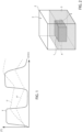
- Figure 1 illustrates the temperature of the electric device as a function of time in relation to an operation curve T of the same.
- the above-mentioned electric devices may be exemplified by an ON-OFF curve or "square wave" representing the alternation between operating state and switched-off state.
- the free air cooling of the electric devices in their housing is not enough since the temperature T' tends to continuously increase at each activation cycle of the electric device.
- conditioning systems configured to actively cool the electric device, for example using forced ventilation or actual heat exchangers forming part of the refrigerant cycle conditioning systems.
- active conditioning systems are bulky and, thus, reduce the vehicle's useful space, making it difficult to assemble and house other vehicle elements.
- the purpose of this invention is to meet the needs outlined above in an optimal and inexpensive way.
- Figure 2 illustrates an assembly, for example a vehicle, comprising an electric device 1, such as an inverter, a DC/DC converter, or a PDU (power distribution unit), used, for example, in a vehicle system (not illustrated).
- an electric device 1 such as an inverter, a DC/DC converter, or a PDU (power distribution unit), used, for example, in a vehicle system (not illustrated).
- PDU power distribution unit
- the electric device 1 is housed in a container 2 defining a space 3 for housing, advantageously insulated from the outside.
- the device 1 is connected to the container 2 via at least one mechanical connection 4, such as, for example, connecting rods, elastic connections, welding, or connections in the form of housing electric cables/busbars as in the example illustrated in Figures 3 and 4 , thus also providing an electrical connection outside the container 2.
- a mechanical connection 4 such as, for example, connecting rods, elastic connections, welding, or connections in the form of housing electric cables/busbars as in the example illustrated in Figures 3 and 4 , thus also providing an electrical connection outside the container 2.
- a passive fluid conditioning system comprising a liquid fluid 5 housed inside the space 3 hermetically sealed from the outside and so as to submerge the device 1 at least partially.
- the box 2 acts as a conditioning system when filled, at least partially, with liquid fluid 5.
- this liquid fluid 5 is thermally conductive and electrically insulating.
- An example of this liquid fluid 5 consists of the oils or liquid salts 3M Novec 7500, MIVOLT DF7, or CARGILL 01973.
- the liquid fluid 5 could consist of a phase change material such as paraffin waxes.
- the liquid fluid entirely submerges the electric device 1 on each outer surface.
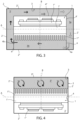
- the container 2 is schematically illustrated comprising a pair of first walls 2' facing each other and spaced apart along a first axis A, or longitudinal axis, and a pair of second walls 2" facing each other and spaced apart along a second axis B, or vertical axis, advantageously perpendicular to the first axis A.
- the first and second pair of walls 2', 2" are connected to each other in order to define the space 3.
- the box 3 is made of one or more elements connected together and of different shapes and types compared to what is illustrated.
- the mechanical connection is realised using a box-shaped element 4 fixed to the container 2 and dividing the space 3 into two portions, a first portion 3a outside the box-shaped element and a second portion 3b inside the box-shaped element 4.
- the box-shaped element 4 also defines a first opening 4a and a second opening 4b configured to enable fluidic communication between the first and second portion 3a, 3b of the space 3.
- the box-shaped element 4 comprises a pair of first walls 4' facing each other along the direction of the first axis A and a second wall 4" extending transversely to the pair of first walls 4' and advantageously perpendicular to these.
- the first and second openings 4a, 4b are preferably formed in the pair of first walls 4', one for each wall 4', while the electric device 1 is placed between the first pair of walls, for mechanical friction coupling friction, above the first and second openings 4a, 4b, i.e. along the direction of the second axis B.
- the pair of first walls 4' is fixed to one of the second pair of walls 2", for example the lower one along the direction of the second axis B.
- the pair of first walls 4' is also spaced apart along the direction of the first axis A in relation to the first walls 2' of the box 2 and the second wall 4" is spaced apart in relation to the wall 2" opposite the one for fastening the first walls 4' so as to create a channel between the openings 4a, 4b.
- the electric device 1 comprises a support portion 1' that carries an electronic processing portion 1" on one side and a dissipation portion 1′′′ on the opposite side to the first side. At least the dissipation portion 1′′′ is wet by the liquid fluid 5.
- the support portion 1' is housed via friction and hermetically sealed inside the box-shaped element 4 keeping the electronic processing portion 1" insulated from the fluid 5, i.e. facing the second wall 2", and the dissipation portion 1′′′ submerged in the fluid 5.
- the dissipation portion 1′′′ comprises a profile, for example finned, configured to ease the exchange of heat with the outside to dissipate the heat generated by the electronic processing portion 1" that passes via the support portion 1'.
- the electronic device 1' is made similarly to the embodiment in Figure 3 comprising, i.e., a support portion 1', an electronic processing portion 1", and a dissipation portion 1′′′.
- the support portion 1' is directly connected to the box 2 and the mechanical connection 4 is thus made via friction/shape coupling via the walls of a pair of walls of the latter opposite each other along the first axis A.
- the device 1 divides the space 3 into a lower portion 3' along the axis B compared to an upper portion 3" along the axis B, fluidically separated between them thanks to the mechanical coupling 4 between box 2 and electric device 1.
- the device 1 is placed so that it is opposite along the direction of the second axis B in relation to the embodiment in Figure 3 , i.e. the dissipation portion 1′′′ is placed above the electronic processing portion 1".
- the dissipation portion 1′′′ is housed in the upper portion 3" of the space 3 compared to the direction of gravity, which houses the liquid fluid 5 that completely wets the dissipation portion 1′′′.
- the liquid fluid makes it possible to cool the electric device 1 more.
- the liquid fluid lets heat disperse more rapidly (T" curve), thus maintaining the temperature of the electric device 1 below a pre-determined safety threshold temperature.
- the operation is similar to that described above.
- the cooling is improved.
- the heat transmitted by the dissipation means 1′′′ heats the fluid 5 that tends to leave the opening 4b, circulate around the walls 4', 4", cooling down and returning from the opening 4a near the dissipation means 1′′′.
- the recirculation of the liquid 5 described above makes it possible to increase the dissipation of the heat of the electric device 1, making the cooling system even more effective.
- the operation is similar to that described above in Figure 3 . Therefore, in this case, the movement of the liquid fluid 5 is provided by the fact that the dissipation portion 1′′′ faces upwards, in relation to the vertical, and thus the heated fluid tends to generate a convective motion that tends to move the liquid fluid increasing, similarly to the embodiment in Figure 3 , its capacity to dissipate heat.
- the system is basically applicable, without additional bulk and with a reduced increase in weight, to any type of electric device without needing to change its fastening nor its arrangement.
- the mechanical coupling 4 and the electric device 1 can be made with any shape and type suitable for this purpose.
- the liquid fluid can be of various chemical compositions as long as it is thermally conductive and electrically insulating.
- the electric device can be of any kind using electricity, such as a pure electric, electronic, or electromechanical device, such as an electric machine.
Landscapes
- Engineering & Computer Science (AREA)
- Microelectronics & Electronic Packaging (AREA)
- Physics & Mathematics (AREA)
- Thermal Sciences (AREA)
- Cooling Or The Like Of Electrical Apparatus (AREA)
Abstract
A vehicle equipped with a cooling system for an electric device (1), comprising a box (2) suitable for defining a space (3) suitable for housing the electric device (1) and a mechanical connection (4) for mechanically connecting the electric device (1) to said box (2), the cooling system comprising a liquid fluid (5) housed hermetically in the space (3) of the box (2) so as to submerge, at least partially, the electric device (1).
Description
- This patent application claims priority from
Italian patent application no. 102023000001719 filed on 02 February 2023 - This invention relates to a vehicle comprising a cooling system for an electric device.
- This invention has its preferred, though not exclusive, application in cooling an electric device for vehicle uses such as a power electronics system. This application will be referred to below by way of example.
- There is an ever greater need to use at least partially electric vehicles in order to reduce vehicle consumption and, thus, environmental emissions.
- At least partially electric vehicles use, as known, electric machines that exchange electricity, in use or being generated, with energy storage means, such as battery packs.
- The electricity passing through the above-mentioned elements, and in relation to other elements using or producing it in the vehicle, is channelled by electric devices, such as, for example, inverters or PDUs (power distribution units).
- These electric devices are placed inside protective housings, usually metal boxes, and fixed to them using appropriate fasteners. The inside of these protective boxes is normally empty, i.e. a space housing air.
- These elements managing the flow of electricity between the various vehicle elements tend to heat up as illustrated by way of example in
Figure 1 . -
Figure 1 illustrates the temperature of the electric device as a function of time in relation to an operation curve T of the same. Usually, the above-mentioned electric devices may be exemplified by an ON-OFF curve or "square wave" representing the alternation between operating state and switched-off state. - As illustrated by the T' curve, the free air cooling of the electric devices in their housing is not enough since the temperature T' tends to continuously increase at each activation cycle of the electric device.
- Thus, it is known to provide conditioning systems configured to actively cool the electric device, for example using forced ventilation or actual heat exchangers forming part of the refrigerant cycle conditioning systems.
- Clearly, these active conditioning systems require power to be able to operate, reducing the overall efficiency of the vehicle.
- In addition, active conditioning systems are bulky and, thus, reduce the vehicle's useful space, making it difficult to assemble and house other vehicle elements.
- Again, the above-mentioned active conditioning systems often require maintenance, which entail vehicle stoppages that further increase the vehicle operating costs.
- There is, thus, a need to cool electric devices for the vehicle in an efficient, compact, and cost-effective manner.
- The purpose of this invention is to meet the needs outlined above in an optimal and inexpensive way.
- Said object is achieved by means of a vehicle as claimed in the appended claims.
- For a better understanding of this invention, a preferred embodiment is described below by way of non-limiting example and with reference to the accompanying drawings, wherein:
-
Figure 1 is a diagram illustrating the change in temperature as a function of time of an electric device during its operation; -
Figure 2 illustrates a first schematic embodiment of an electric device comprising a cooling system according to the invention; -
Figure 3 illustrates a second schematic embodiment of an electric device comprising a cooling system according to the invention; and -
Figure 4 illustrates a third schematic embodiment of an electric device comprising a cooling system according to the invention. -
Figure 2 illustrates an assembly, for example a vehicle, comprising anelectric device 1, such as an inverter, a DC/DC converter, or a PDU (power distribution unit), used, for example, in a vehicle system (not illustrated). - The
electric device 1 is housed in acontainer 2 defining aspace 3 for housing, advantageously insulated from the outside. - The
device 1 is connected to thecontainer 2 via at least onemechanical connection 4, such as, for example, connecting rods, elastic connections, welding, or connections in the form of housing electric cables/busbars as in the example illustrated inFigures 3 and 4 , thus also providing an electrical connection outside thecontainer 2. - According to the invention, a passive fluid conditioning system is provided comprising a
liquid fluid 5 housed inside thespace 3 hermetically sealed from the outside and so as to submerge thedevice 1 at least partially. In other words, thebox 2 acts as a conditioning system when filled, at least partially, withliquid fluid 5. - In particular, this
liquid fluid 5 is thermally conductive and electrically insulating. An example of thisliquid fluid 5 consists of the oils or liquid salts 3M Novec 7500, MIVOLT DF7, or CARGILL 01973. - Alternatively, the
liquid fluid 5 could consist of a phase change material such as paraffin waxes. - In the embodiment described, the liquid fluid entirely submerges the
electric device 1 on each outer surface. - In the embodiments in
Figures 3 and 4 , thecontainer 2 is schematically illustrated comprising a pair offirst walls 2' facing each other and spaced apart along a first axis A, or longitudinal axis, and a pair ofsecond walls 2" facing each other and spaced apart along a second axis B, or vertical axis, advantageously perpendicular to the first axis A. The first and second pair ofwalls space 3. In any case, it is clearly possible that thebox 3 is made of one or more elements connected together and of different shapes and types compared to what is illustrated. - In the embodiment in
Figure 3 , the mechanical connection is realised using a box-shaped element 4 fixed to thecontainer 2 and dividing thespace 3 into two portions, a first portion 3a outside the box-shaped element and asecond portion 3b inside the box-shaped element 4. - The box-
shaped element 4 also defines afirst opening 4a and a second opening 4b configured to enable fluidic communication between the first andsecond portion 3a, 3b of thespace 3. - More specifically, the box-
shaped element 4 comprises a pair of first walls 4' facing each other along the direction of the first axis A and asecond wall 4" extending transversely to the pair of first walls 4' and advantageously perpendicular to these. - The first and
second openings electric device 1 is placed between the first pair of walls, for mechanical friction coupling friction, above the first andsecond openings - Specifically, the pair of first walls 4' is fixed to one of the second pair of
walls 2", for example the lower one along the direction of the second axis B. The pair of first walls 4' is also spaced apart along the direction of the first axis A in relation to thefirst walls 2' of thebox 2 and thesecond wall 4" is spaced apart in relation to thewall 2" opposite the one for fastening the first walls 4' so as to create a channel between theopenings - In further detail, the
electric device 1 comprises a support portion 1' that carries anelectronic processing portion 1" on one side and adissipation portion 1‴ on the opposite side to the first side. At least thedissipation portion 1‴ is wet by theliquid fluid 5. - In the embodiment described, the support portion 1' is housed via friction and hermetically sealed inside the box-
shaped element 4 keeping theelectronic processing portion 1" insulated from thefluid 5, i.e. facing thesecond wall 2", and thedissipation portion 1‴ submerged in thefluid 5. - As known, the
dissipation portion 1‴ comprises a profile, for example finned, configured to ease the exchange of heat with the outside to dissipate the heat generated by theelectronic processing portion 1" that passes via the support portion 1'. - In the embodiment in
Figure 4 , the electronic device 1' is made similarly to the embodiment inFigure 3 comprising, i.e., a support portion 1', anelectronic processing portion 1", and adissipation portion 1‴. - In any case, in this embodiment, the support portion 1' is directly connected to the
box 2 and themechanical connection 4 is thus made via friction/shape coupling via the walls of a pair of walls of the latter opposite each other along the first axis A. - In this way, the
device 1 divides thespace 3 into a lower portion 3' along the axis B compared to anupper portion 3" along the axis B, fluidically separated between them thanks to themechanical coupling 4 betweenbox 2 andelectric device 1. - In addition, the
device 1 is placed so that it is opposite along the direction of the second axis B in relation to the embodiment inFigure 3 , i.e. thedissipation portion 1‴ is placed above theelectronic processing portion 1". In other words, thedissipation portion 1‴ is housed in theupper portion 3" of thespace 3 compared to the direction of gravity, which houses theliquid fluid 5 that completely wets thedissipation portion 1‴. - The operation of the embodiment of the vehicle according to the invention described above is the following.
- Essentially, according to the embodiment in
Figure 2 , as illustrated in the graph inFigure 1 , the liquid fluid makes it possible to cool theelectric device 1 more. Thus, in the inactivity phase of the operation curve T of theelectric device 1, the liquid fluid lets heat disperse more rapidly (T" curve), thus maintaining the temperature of theelectric device 1 below a pre-determined safety threshold temperature. - Referring to the particular operation of the embodiment in
Figure 3 , the operation is similar to that described above. In any case, thanks to the embodiment illustrated where themechanical element 4 defines a passage channel with thebox 2 for thefluid 5 via the twoopenings fluid 5 that tends to leave the opening 4b, circulate around thewalls 4', 4", cooling down and returning from the opening 4a near the dissipation means 1‴. The recirculation of the liquid 5 described above, makes it possible to increase the dissipation of the heat of theelectric device 1, making the cooling system even more effective. - Referring to the particular operation of the embodiment in
Figure 4 , the operation is similar to that described above inFigure 3 . Therefore, in this case, the movement of theliquid fluid 5 is provided by the fact that thedissipation portion 1‴ faces upwards, in relation to the vertical, and thus the heated fluid tends to generate a convective motion that tends to move the liquid fluid increasing, similarly to the embodiment inFigure 3 , its capacity to dissipate heat. - The advantages of a vehicle according to the invention are clear from the foregoing.
- Thanks to the cooling system described, it is possible to effectively, cost-effectively, and compactly cool an electronic device, thus solving the issues related to the prior art systems.
- In particular, it is possible to make the electric devices operate at greater frequencies, without having to forcibly increase the dimensions of the housing box or provide active conditioning systems.
- In particular, the system is basically applicable, without additional bulk and with a reduced increase in weight, to any type of electric device without needing to change its fastening nor its arrangement.
- The particular arrangements of the embodiments in
Figures 3 and 4 , which require a particular arrangement of the electric device, therefore make it possible to obtain additional, heat-dissipating capacity from the liquid fluid, thus further improving the capacity of the cooling system. - Lastly, it is clear that modifications and variations may be made to the vehicle according to this invention, without, however, departing from the scope of protection defined by the claims.
- Clearly, as demonstrated, the
mechanical coupling 4 and theelectric device 1 can be made with any shape and type suitable for this purpose. - As mentioned, the liquid fluid can be of various chemical compositions as long as it is thermally conductive and electrically insulating.
- Again, the electric device can be of any kind using electricity, such as a pure electric, electronic, or electromechanical device, such as an electric machine.
Claims (9)
- A vehicle comprising an electric device (1) and a cooling system for said device, said cooling system comprising a box (2) suitable for defining a space (3) suitable for housing said electric device (1) and a mechanical connection (4) for mechanically connecting said electric device (1) to said box (2), said cooling system comprising a liquid fluid (5) housed hermetically in said space (3) of said box (2) so as to submerge, at least partially, said electric device (1)
wherein said liquid fluid (5) is thermally conductive and electrically insulating. - The vehicle according to claim 1, wherein said liquid fluid (5) completely submerges said electric device (1) .
- The vehicle according to claim 2, wherein said liquid fluid is an oil or a liquid salt or a phase change material.
- The vehicle according to one of the preceding claims, wherein said electric device (1) comprises a support portion (1') an electronic processing portion (1") carried by a part of said support portion (1') and a dissipation portion (1‴) carried on the opposite side of said support portion (1') with respect to said electronic processing portion (1‴), at least said dissipation portion (1‴) being immersed in said liquid fluid (5).
- The vehicle according to claim 4, wherein said support portion (1‴) is carried directly by said box (2), said mechanical connection (4) being a contact connection between first walls (2') of said box (2) and said support portion (1"), said space (3) being divided by the coupling of said support portion (1") and said walls (2') into a first and a second portion (3', 3"), said second portion (3") being placed above the first (3') and housing said liquid fluid (5), said dissipation portion (1") being housed in said second portion (3").
- The vehicle according to claim 4, wherein said mechanical connection (4) comprises a box-shaped element comprising a pair of first walls (4') and a second wall (4") extending transversely between said pair of first walls (4 '), said support portion (1') being carried between said first walls (4') and said electronic processing portion (1'') facing said second wall (1' '), said space 3 comprised between said boxed element and said box (2) being occupied by said liquid fluid (5).
- The vehicle according to claim 6, in which a channel (3a, 3b) is defined between said first walls (4') and said second wall (4") and said box (2) which allows the circulation of said fluid liquid (5) around said boxed element.
- The vehicle according to claim 7, wherein said first walls (4') each define an opening (4a, 4b) configured to allow the passage of said liquid fluid between an external portion (3a) of said box and an internal portion (3b) to said box.
- The vehicle according to claim 8 in which said openings (4a, 4b) are placed at different heights.
Applications Claiming Priority (1)
| Application Number | Priority Date | Filing Date | Title |
|---|---|---|---|
| IT102023000001719A IT202300001719A1 (en) | 2023-02-02 | 2023-02-02 | VEHICLE INCLUDING A COOLING SYSTEM FOR AN ELECTRIC DEVICE |
Publications (1)
| Publication Number | Publication Date |
|---|---|
| EP4412417A1 true EP4412417A1 (en) | 2024-08-07 |
Family
ID=86007700
Family Applications (1)
| Application Number | Title | Priority Date | Filing Date |
|---|---|---|---|
| EP24155185.2A Pending EP4412417A1 (en) | 2023-02-02 | 2024-02-01 | Vehicle comprising a cooling system for an electric device |
Country Status (2)
| Country | Link |
|---|---|
| EP (1) | EP4412417A1 (en) |
| IT (1) | IT202300001719A1 (en) |
Citations (3)
| Publication number | Priority date | Publication date | Assignee | Title |
|---|---|---|---|---|
| US20070267741A1 (en) * | 2006-05-16 | 2007-11-22 | Hardcore Computer, Inc. | Liquid submersion cooling system |
| US20190090383A1 (en) * | 2017-09-20 | 2019-03-21 | Liquidcool Solutions, Inc. | Liquid submersion cooled electronic systems and devices |
| US20200323109A1 (en) * | 2019-04-02 | 2020-10-08 | Eaton Intelligent Power Limited | Immersion cooling systems and methods for electrical power components |
-
2023
- 2023-02-02 IT IT102023000001719A patent/IT202300001719A1/en unknown
-
2024
- 2024-02-01 EP EP24155185.2A patent/EP4412417A1/en active Pending
Patent Citations (3)
| Publication number | Priority date | Publication date | Assignee | Title |
|---|---|---|---|---|
| US20070267741A1 (en) * | 2006-05-16 | 2007-11-22 | Hardcore Computer, Inc. | Liquid submersion cooling system |
| US20190090383A1 (en) * | 2017-09-20 | 2019-03-21 | Liquidcool Solutions, Inc. | Liquid submersion cooled electronic systems and devices |
| US20200323109A1 (en) * | 2019-04-02 | 2020-10-08 | Eaton Intelligent Power Limited | Immersion cooling systems and methods for electrical power components |
Also Published As
| Publication number | Publication date |
|---|---|
| IT202300001719A1 (en) | 2024-08-02 |
Similar Documents
| Publication | Publication Date | Title |
|---|---|---|
| EP3229572B1 (en) | Immersion cooling systems and methods | |
| JP4231626B2 (en) | Motor drive device for automobile | |
| JP6235605B2 (en) | Battery | |
| JP5488565B2 (en) | Power converter | |
| JP5862608B2 (en) | Battery assembly | |
| JP7091971B2 (en) | Battery unit | |
| CN115606038A (en) | Energy storage device with battery cell modules and cooling device, preferably for an at least partially electrically driven vehicle, and method for producing the energy storage device | |
| WO2009090773A1 (en) | Temperature control mechanism | |
| JPWO2000017994A1 (en) | Automotive motor drive unit | |
| US9059607B2 (en) | Gear-integrated electric motor and electric vehicle | |
| CN115891709B (en) | A charging device and a charging system | |
| KR20160140478A (en) | Battery pack and battery cooling system | |
| JP5976235B1 (en) | Power converter | |
| JP2024172116A (en) | Power Supply | |
| KR102653325B1 (en) | Power converter housing for electric vehicle or hybrid vehicle | |
| JP2015011826A (en) | Battery pack | |
| JP3170783U (en) | Heating module | |
| JP2015075312A (en) | Phase change module and electronic equipment device mounted with the same | |
| EP4687390A1 (en) | Cooling system for an electric device for a vehicle | |
| CN103918121A (en) | Battery cells, battery cell modules, batteries and motor vehicles | |
| JP2015204267A (en) | battery pack | |
| CN115474416A (en) | BDU integrated heat dissipation device and electric vehicle | |
| CN211831667U (en) | Electrical apparatus box and be equipped with its indirect heating equipment | |
| JP7804374B2 (en) | Battery equipment | |
| JPWO2014162652A1 (en) | Power converter |
Legal Events
| Date | Code | Title | Description |
|---|---|---|---|
| PUAI | Public reference made under article 153(3) epc to a published international application that has entered the european phase |
Free format text: ORIGINAL CODE: 0009012 |
|
| STAA | Information on the status of an ep patent application or granted ep patent |
Free format text: STATUS: THE APPLICATION HAS BEEN PUBLISHED |
|
| AK | Designated contracting states |
Kind code of ref document: A1 Designated state(s): AL AT BE BG CH CY CZ DE DK EE ES FI FR GB GR HR HU IE IS IT LI LT LU LV MC ME MK MT NL NO PL PT RO RS SE SI SK SM TR |
|
| STAA | Information on the status of an ep patent application or granted ep patent |
Free format text: STATUS: REQUEST FOR EXAMINATION WAS MADE |
|
| 17P | Request for examination filed |
Effective date: 20250205 |