EP4412368A2 - Verfahren zur steuerung der aktivierung von bwp, benutzergerät und basisstation - Google Patents
Verfahren zur steuerung der aktivierung von bwp, benutzergerät und basisstation Download PDFInfo
- Publication number
- EP4412368A2 EP4412368A2 EP24183448.0A EP24183448A EP4412368A2 EP 4412368 A2 EP4412368 A2 EP 4412368A2 EP 24183448 A EP24183448 A EP 24183448A EP 4412368 A2 EP4412368 A2 EP 4412368A2
- Authority
- EP
- European Patent Office
- Prior art keywords
- bwp
- component carrier
- base station
- configuration information
- primary cell
- Prior art date
- Legal status (The legal status is an assumption and is not a legal conclusion. Google has not performed a legal analysis and makes no representation as to the accuracy of the status listed.)
- Pending
Links
Images


Classifications
-
- H—ELECTRICITY
- H04—ELECTRIC COMMUNICATION TECHNIQUE
- H04L—TRANSMISSION OF DIGITAL INFORMATION, e.g. TELEGRAPHIC COMMUNICATION
- H04L5/00—Arrangements affording multiple use of the transmission path
- H04L5/0091—Signalling for the administration of the divided path, e.g. signalling of configuration information
- H04L5/0096—Indication of changes in allocation
- H04L5/0098—Signalling of the activation or deactivation of component carriers, subcarriers or frequency bands
-
- H—ELECTRICITY
- H04—ELECTRIC COMMUNICATION TECHNIQUE
- H04L—TRANSMISSION OF DIGITAL INFORMATION, e.g. TELEGRAPHIC COMMUNICATION
- H04L5/00—Arrangements affording multiple use of the transmission path
- H04L5/0091—Signalling for the administration of the divided path, e.g. signalling of configuration information
- H04L5/0092—Indication of how the channel is divided
-
- H—ELECTRICITY
- H04—ELECTRIC COMMUNICATION TECHNIQUE
- H04W—WIRELESS COMMUNICATION NETWORKS
- H04W72/00—Local resource management
- H04W72/04—Wireless resource allocation
-
- H—ELECTRICITY
- H04—ELECTRIC COMMUNICATION TECHNIQUE
- H04W—WIRELESS COMMUNICATION NETWORKS
- H04W72/00—Local resource management
- H04W72/04—Wireless resource allocation
- H04W72/044—Wireless resource allocation based on the type of the allocated resource
- H04W72/0453—Resources in frequency domain, e.g. a carrier in FDMA
-
- H—ELECTRICITY
- H04—ELECTRIC COMMUNICATION TECHNIQUE
- H04W—WIRELESS COMMUNICATION NETWORKS
- H04W72/00—Local resource management
- H04W72/20—Control channels or signalling for resource management
- H04W72/23—Control channels or signalling for resource management in the downlink direction of a wireless link, i.e. towards a terminal
-
- H—ELECTRICITY
- H04—ELECTRIC COMMUNICATION TECHNIQUE
- H04L—TRANSMISSION OF DIGITAL INFORMATION, e.g. TELEGRAPHIC COMMUNICATION
- H04L5/00—Arrangements affording multiple use of the transmission path
- H04L5/0001—Arrangements for dividing the transmission path
- H04L5/0003—Two-dimensional division
- H04L5/0005—Time-frequency
- H04L5/0007—Time-frequency the frequencies being orthogonal, e.g. OFDM(A) or DMT
- H04L5/001—Time-frequency the frequencies being orthogonal, e.g. OFDM(A) or DMT the frequencies being arranged in component carriers
-
- H—ELECTRICITY
- H04—ELECTRIC COMMUNICATION TECHNIQUE
- H04W—WIRELESS COMMUNICATION NETWORKS
- H04W36/00—Hand-off or reselection arrangements
- H04W36/0005—Control or signalling for completing the hand-off
- H04W36/0055—Transmission or use of information for re-establishing the radio link
- H04W36/0072—Transmission or use of information for re-establishing the radio link of resource information of target access point
-
- H—ELECTRICITY
- H04—ELECTRIC COMMUNICATION TECHNIQUE
- H04W—WIRELESS COMMUNICATION NETWORKS
- H04W36/00—Hand-off or reselection arrangements
- H04W36/08—Reselecting an access point
Definitions
- the present disclosure relates to the technical field of communications, and in particular to a method for controlling activation of a BWP, a user equipment and a base station.
- a cell In the 5 th Generation (5G) wireless communication system using a new radio access (NR) technique, a cell supports a maximum system bandwidth of 400MHz, which is much higher than a maximum LTE system bandwidth of 20MHz, so as to support a larger system and user throughput.
- a user equipment UE
- the 5G NR system also supports dynamic and flexible bandwidth allocation, where the system bandwidth is divided into multiple bandwidth parts (BWPs) to support accesses of narrowband user terminals or user terminals in an energy-saving mode.
- BWPs bandwidth parts
- the UE can support multiple BWPs, the power consumption of the UE may increase, if all the BWPs are simultaneously activated. Therefore, how to flexibly control activated states of multiple BWPs for a UE becomes a technical problem that needs to be solved urgently.
- an embodiment of the present disclosure provides a method for controlling activation of a bandwidth part (BWP), including:
- an embodiment of the present disclosure further provides a method for controlling activation of a bandwidth part (BWP), including:
- an embodiment of the present disclosure further provides a user equipment, including:
- an embodiment of the present disclosure further provides a base station, including:
- an embodiment of the present disclosure further provides an electronic device, including:
- an embodiment of the present disclosure further provides an electronic device, including:
- an embodiment of the present disclosure further provides a computer-readable storage medium, on which a program is stored.
- the program is executed by a processor to implement steps in the method for controlling activation of a bandwidth part (BWP) as described in the above first aspect and/or in the second aspect.
- BWP bandwidth part
- FIG. 1 is a flowchart of a method for controlling activation of a bandwidth part (BWP) according to an embodiment of the present disclosure. As shown in FIG. 1 , the method includes the following steps 101 to 103.
- BWP bandwidth part
- Step 101 includes: receiving and saving BWP configuration information transmitted by a base station, where the BWP configuration information includes BWP identification information.
- the method for controlling activation of a BWP provided by embodiments of the present disclosure is applied in a user equipment (UE) to manage an activated state of BWP(s) corresponding to each component carrier.
- UE user equipment
- the base station first configures a BWP for a UE to access the base station.
- the base station transmits the BWP configuration information to the UE, and the UE may receive and save the BWP configuration information, i.e., saving a correspondence between each component carrier and a default BWP.
- each component carrier is configured with a BWP set, and information about one or more BWPs is stored in the BWP set, that is, one component carrier may correspond to one or more BWPs.
- every BWPs may be numbered.
- the BWP identification information may be configured to a UE in an explicit or implicit manner.
- the explicit manner includes that a dedicated information bit string is configured in the configuration information for each BWP to indicate index information of the BWP.
- the implicit manner includes that a serial number of each BWP in a BWP list of the configuration information is an index of the BWP.
- the first BWP in the list is numbered as 0, and BWPs subsequent to the first BWP are respectively numbered as 1, 2, 3, and so on.
- Step 102 includes: receiving a BWP activation command transmitted by the base station.
- the base station may transmit a BWP activation command to the base station through Layer 1 (L1) signaling or Layer 2 (L2) signaling, and the BWP activation command may indicate index information of to-be-activated BWP(s) in an explicit or implicit manner.
- L1 Layer 1
- L2 Layer 2
- the explicit manner includes: carrying index information of a target and to-be-activated BWP in an activation signaling.
- the implicit manner includes: carrying a bitmap in an activation signaling, each bit corresponding to one BWP, indicating to activate the BWP when the corresponding bit takes a first value; and indicating to deactivate the BWP when the corresponding bit takes a second value.
- a position where each indication bit is located in the bitmap corresponds to an index of a corresponding BWP.
- the first bit in the bitmap corresponds to a BWP numbered as 0
- the second bit in the bitmap corresponds to a BWP numbered as 1, and so on.
- no operation is performed when a bit corresponding to the BWP in the received activation signaling takes a first value.
- a BWP is in a deactivated state
- no operation is performed when a bit corresponding to the BWP in the received activation signaling takes a second value.
- Step 103 includes: performing BWP activation with a BWP identifier indicated by the BWP activation command.
- a UE may perform BWP activation with the BWP identifier indicated by the BWP activation command, thereby implementing a control of BWP activation.
- BWP configuration information transmitted by a base station is received and saved, and the BWP configuration information includes BWP identification information; a BWP activation command transmitted by the base station is received; and a BWP is activated based on a BWP identifier indicated by the BWP activation command.
- BWPs are numbered, the activation command indicates a BWP that needs to be activated, and the BWP is activated by a UE, thereby improving the flexibility of BWP activation control.
- the method further includes:
- a component carrier In a case that a component carrier is activated, data can be normally transmitted and received on the component carrier only when there is an activated BWP on the component carrier.
- the above-mentioned default BWP refers to a BWP that needs to be activated by default, if a command indicates to activate a component carrier, but the command does not specify a BWP on the component carrier requiring to be activated.
- the number of the default BWP corresponding to each component carrier may be set according to actual needs, and may be one or more, which is not specifically limited herein.
- the base station may transmit a component carrier activation signaling to the base station by a control element (CE) of a medium access control (MAC) layer.
- CE control element
- MAC medium access control
- the UE After receiving the component carrier activation signaling, the UE obtains the first target component carrier that needs to be activated, which is indicated by the component carrier activation signaling, then obtains a default BWP corresponding to the first target component carrier according to the previously stored BWP configuration information, and finally activates the first target component carrier and the default BWP(s) corresponding to the first target component carrier.
- a default BWP corresponding to each component carrier is configured in BWP configuration information, and then a first target component carrier and a default BWP corresponding to a first target component carrier are directly activated based on the component carrier activation signaling. Therefore, an activated state of the component carrier and an activated state of a BWP on the component carrier can be controlled through a single signaling, thereby reducing signaling overhead.
- a single signaling is used to simultaneously activate a component carrier and activate a BWP on the component carrier, a transmission delay can be avoided, which is caused by controlling an activated state of the component carrier and an activated state of the BWP on the component carrier through separate signalings.
- a manner where a base station configures BWP configuration information for indicating a default BWP corresponding to each component carrier can be set according to actual needs.
- the configuring manner can be implemented in any of the following manners:
- the activated BWP may be deactivated based on signaling. Specifically, referring to FIG. 3 , subsequent to the above step 101, the method further includes steps 106 and 107.
- Step 106 includes: receiving a BWP deactivation command transmitted by the base station, where the BWP deactivation command is used for adjusting an activated BWP on a second target component carrier to a deactivated state.
- the base station may transmit a BWP deactivation command to a UE through L1 or L2 signaling.
- the signaling may include an identification indication of a BWP that needs to be deactivated.
- the UE may obtain the second target component carrier where the BWP needs to be deactivated is located, by inquiring the previously saved BWP configuration information.
- Step 107 includes: deactivating the second target component carrier, or deactivating the second target component carrier and a corresponding BWP on the second target component carrier, in a case that an activated BWP to be adjusted on the second target component carrier is a last activated BWP.
- a BWP specified in the BWP deactivation command may be directly deactivated; and in a case that only the last activated BWP exists on the second target component carrier, the second target component carrier may be deactivated, or both the second target component carrier and a corresponding BWP (that is, a BWP specified in the deactivation command) on the second target component carrier.
- a BWP specified in the BWP deactivation command includes each of one or more activated BWPs on the second target component carrier, which also means performing a deactivation on the last activated BWP on the second target component carrier
- the second target component carrier may be deactivated in this case, or both the second target component carrier and a corresponding BWP on the second target component carrier (that is, a BWP specified in the deactivation command) may be deactivated in this case. Since the deactivation of a component carrier can be achieved by only indicating a BWP deactivation during a deactivation process, the signaling overhead is further reduced.
- the activated BWP may be deactivated in accordance with a signaling. Specifically, referring to FIG. 4 , subsequent to the above step 101, the method further includes steps 108 and 109.
- Step 108 includes: receiving a component carrier deactivation signaling transmitted by the base station.
- the base station may transmit a component carrier deactivation signaling to a UE through a control element of a medium access control layer (MAC CE).
- the component carrier deactivation signaling includes a third target component carrier that needs to be deactivated.
- the UE may obtain all BWPs on the third target component carrier based on the previously saved BWP configuration information.
- the third target component carrier may include one or more BWPs in an activated state, and may also include one or more BWPs in a deactivated state.
- Step 109 includes: deactivating, based on the component carrier deactivation signaling, a third target component carrier, or a third target component carrier and each of one or more activated BWPs on the third target component carrier.
- a UE may deactivate the third target component carrier, or may deactivate the third target component carrier and each of the one or more activated BWPs on the third target component carrier. Since the deactivation of a BWP can be achieved only based on a component carrier deactivation signaling, the signaling overhead is further reduced.
- the BWP activation command is used for adjusting a deactivated BWP on a fourth target component carrier to an activated state.
- the performing BWP activation with the BWP identifier indicated by the BWP activation command includes: activating the fourth target component carrier and a BWP designated to be activated through the BWP activation command, in a case that the fourth target component carrier is in a deactivated state.
- the base station may transmit a BWP activation command to a UE through L1 signaling or L2 signaling, and the BWP activation command includes a BWP that needs to be activated.
- the UE may obtain the fourth target component carrier corresponding to the BWP(s) that needs to be activated by inquiring the previously saved BWP configuration information.
- the UE determines whether the fourth target component carrier is in an activated state, may directly activate a BWP designated to be activated through the BWP activation command if the fourth target component carrier is currently in an activated state, and may activate the fourth target component carrier and a BWP designated to be activated through the BWP activation command if the fourth target component carrier is currently in a deactivated state.
- a component carrier can be controlled to be activated only through a BWP activation command, thereby further reducing the signaling overhead.
- a UE usually accesses to only one base station, and of course, a UE can also access to two base stations, where one of the base stations is a primary base station and the other one is a secondary base station.
- the foregoing BWP configuration information may include BWP configuration information of the primary base station and BWP configuration information of the secondary base station.
- the primary base station configures BWP configuration information of the secondary base station for the UE.
- the BWP configuration information of the secondary base station is used to indicate a component carrier where a primary cell of the secondary base station is located, and default BWP information corresponding to each component carrier.
- the above method further includes: actively activating, by the UE, a default BWP corresponding to the component carrier where the primary cell in the secondary base station is located.
- the UE may activate the default BWP corresponding to the component carrier where the primary cell in the secondary base station is located in accordance with indications, thereby implementing data transmission to the secondary base station. It should be understood that for processes of activating and deactivating a BWP corresponding to a component carrier where a secondary cell in the secondary base station is located and a non-default BWP corresponding to a component carrier where a primary cell in the secondary base station is located, reference can be made to the foregoing embodiments, and details are not described herein again.
- the base station may further perform handover on the primary cell. Specifically, subsequent to the above step 101, the method further includes:
- a base station can control a UE to be switched to a target primary cell through a primary cell handover command, so as to supply a better service to the UE.
- a default BWP on the target primary cell is indicated in the primary cell handover command. Therefore, the UE can complete the subsequent target cell handover procedure on the default BWP.
- FIG. 5 Reference is made to FIG. 5 , and the present disclosure further provides a method for controlling activation of a bandwidth part (BWP), which includes steps 501 and 502.
- BWP bandwidth part
- Step 501 includes: transmitting BWP configuration information to a UE, where the BWP configuration information includes BWP identification information.
- the method for controlling activation of a BWP provided by embodiments of the present disclosure is applied in a base station to control an activated state of BWP(s) corresponding to each component carrier.
- the base station first configures a BWP for a UE to access the base station.
- the base station transmits the BWP configuration information to the UE, and the UE may receive and save the BWP configuration information, thereby saving a correspondence between each component carrier and a default BWP.
- each component carrier is configured with a BWP set, and information about one or more BWPs is stored in the BWP set, that is, one component carrier may correspond to one or more BWPs. In an embodiment, all the BWPs may be numbered.
- the BWP identification information may be configured to a UE in an explicit or implicit manner.
- the explicit manner includes that a dedicated information bit string is configured in the configuration information for each BWP to indicate index information of the BWP.
- the implicit manner includes that a serial number of each BWP in a BWP list of the configuration information is an index of the BWP.
- the first BWP in the list is numbered as 0, and BWPs subsequent to the first BWP are respectively numbered as 1, 2, 3, and so on.
- Step 502 includes: transmitting a BWP activation command to the UE, where the activation command is used for the UE to perform BWP activation with a BWP identifier indicated by the BWP activation command.
- the base station may transmit a BWP activation command to the UE through L1 signaling or L2 signaling, and the BWP activation command may indicate index information of to-be-activated BWP(s) in an explicit or implicit manner.
- the explicit manner includes: carrying index information of a target and to-be-activated BWP in an activation signaling.
- the implicit manner includes: carrying a bitmap in an activation signaling, each bit corresponding to one BWP, indicating to activate the BWP when the corresponding bit takes a first value; and indicating to deactivate the BWP when the corresponding bit takes a second value.
- a position where each indication bit is located in the bitmap corresponds to an index of a corresponding BWP.
- the first bit in the bitmap corresponds to a BWP numbered as 0
- the second bit in the bitmap corresponds to a BWP numbered as 1, and so on.
- no operation is performed when a bit corresponding to the BWP in the received activation signaling takes a first value.
- a BWP is in a deactivated state
- no operation is performed when a bit corresponding to the BWP in the received activation signaling takes a second value.
- a UE When receiving the BWP activation command, a UE may perform BWP activation with the BWP identifier indicated by the BWP activation command, thereby implementing a control of BWP activation.
- BWP configuration information transmitted by a base station is received and saved, where the BWP configuration information includes BWP identification information; a BWP activation command transmitted by the base station is received; and BWP activation is performed based on a BWP identifier indicated by the BWP activation command.
- BWPs are numbered, the activation command indicates a BWP that needs to be activated, and the BWP is activated by a UE, thereby improving the flexibility of BWP activation control.
- the BWP configuration information is used to indicate a default BWP corresponding to each component carrier.
- the method further includes: transmitting a component carrier activation signaling to the user equipment, where the component carrier activation signaling is used for the user equipment to activate a first target component carrier and a default BWP corresponding to the first target component carrier.
- the above-mentioned default BWP refers to a BWP that needs to be activated by default when a command indicates to activate a BWP, but the command does not indicate that other BWPs on the component carrier require to be activated.
- the number of the default BWPs corresponding to each component carrier may be set according to actual demands, and may be one or more, which is not specifically limited herein.
- the base station may transmit a component carrier activation signaling to the base station by an MAC CE.
- the component carrier activation signaling carries a first target component carrier that needs to be activated, and all BWPs on the first target component carrier are in a deactivated state.
- the UE After receiving the component carrier activation signaling, the UE obtains the first target component carrier that needs to be activated, which is indicated by the component carrier activation signaling, then obtains a default BWP corresponding to the first target component carrier according to the previously stored BWP configuration information, and finally activates the first target component carrier and the default BWP(s) corresponding to the first target component carrier.
- a default BWP corresponding to each component carrier is configured in BWP configuration information, and then a first target component carrier and a default BWP corresponding to a first target component carrier are directly activated in accordance with the component carrier activation signaling. Therefore, an activated state of the component carrier and an activated state of a BWP on the component carrier can be controlled through a single signaling, thereby reducing signaling overhead.
- a single signaling is used to activate a component carrier and activate a BWP on the component carrier at a same time, a transmission delay can be avoided, which is caused by controlling an activated state of the component carrier and an activated state of the BWP on the component carrier through separate signalings.
- a manner where a base station configures BWP configuration information for indicating a default BWP corresponding to each component carrier can be set according to actual needs.
- the configuring manner can be implemented in any of the following manners:
- the activated BWP may be deactivated through signaling.
- the method further includes: transmitting a BWP deactivation command to the user equipment.
- the BWP deactivation command is used for instructing the user equipment to adjust an activated BWP on a second target component carrier to a deactivated state; and the BWP deactivation command is used for instructing the user equipment to deactivate the second target component carrier, or deactivate the second target component carrier and a corresponding BWP on the second target component carrier, in a case that the activated BWP to be adjusted is a last activated BWP on the second target component carrier.
- the base station may transmit a BWP deactivation command to a UE through L1 or L2 signaling, which may include a BWP that needs to be deactivated.
- the UE may obtain the second target component carrier where the BWP needs to be deactivated is located, by inquiring previously saved BWP configuration information.
- the UE when a UE performs deactivation on a BWP on the second target component carrier, in a case that there are multiple activated BWPs on the second target component carrier, the UE may directly deactivate a BWP specified in the BWP deactivation command; and in a case that only the last activated BWP exists on the second target component carrier, the UE may deactivate the second target component carrier, or both the second target component carrier and a corresponding BWP (that is, a BWP specified in the deactivation signaling) on the second target component carrier. Since the deactivation of a component carrier can be achieved by only indicating a BWP deactivation during a deactivation process, the signaling overhead is further reduced.
- the activated BWP may be deactivated through signaling.
- the method further includes: transmitting a component carrier deactivation signaling to the user equipment.
- the component carrier deactivation signaling is configured to instruct the user equipment to deactivate a third target component carrier, or to instruct the user equipment to deactivate a third target component carrier and each of one or more activated BWPs on the third target component carrier.
- the base station may transmit a component carrier deactivation signaling to a UE through a control element of a medium access control layer (MAC CE).
- the component carrier deactivation signaling includes a third target component carrier that needs to be deactivated.
- the UE may obtain all BWPs on the third target component carrier based on the previously saved BWP configuration information.
- the third target component carrier may include one or more BWPs in an activated state, and may also include one or more BWPs in a deactivated state.
- a UE may deactivate the third target component carrier, or may deactivate the third target component carrier and each of the one or more activated BWPs on the third target component carrier. Since the deactivation of a BWP can be achieved only based on a component carrier deactivation signaling, the signaling overhead is further reduced.
- the BWP activation command is used for adjusting a deactivated BWP on a fourth target component carrier to an activated state; and the user equipment activates the fourth target component carrier and a BWP designated to be activated through the BWP activation command, in a case that the fourth target component carrier is in an inactive state.
- the base station may transmit a BWP activation command to a UE through L1 signaling or L2 signaling, and the BWP activation command includes a BWP that needs to be activated.
- the UE may obtain the fourth target component carrier corresponding to the BWP(s) that needs to be activated by inquiring the previously saved BWP configuration information.
- the UE determines whether the fourth target component carrier is in an activated state, may directly activate a BWP designated to be activated through the BWP activation command if the fourth target component carrier is currently in an activated state, and may activate the fourth target component carrier and a BWP designated to be activated through the BWP activation command if the fourth target component carrier is currently in a deactivated state.
- a component carrier can be controlled to be activated only through a BWP activation command, thereby further reducing the signaling overhead.
- a UE usually accesses to only one base station, and of course, a UE can also access to two base stations, where one of the base stations is a primary base station and the other one is a secondary base station.
- the foregoing BWP configuration information may include BWP configuration information of the primary base station and BWP configuration information of the secondary base station.
- the primary base station configures BWP configuration information of the secondary base station for the UE.
- the BWP configuration information of the secondary base station is used to indicate a component carrier where a primary cell of the secondary base station is located, and default BWP information corresponding to each component carrier.
- the UE may activate the default BWP corresponding to the component carrier where the primary cell of the secondary base station is located based on an indication, thereby implementing data transmission of the secondary base station. It should be understood that, for processes of activating and deactivating a BWP corresponding to a component carrier where a secondary cell in the secondary base station is located, and a non-default BWP corresponding to a component carrier where a primary cell in the secondary base station is located, reference can be made to the foregoing embodiments, and details are not described herein again.
- the base station may also perform handover on the primary cell. Specifically, subsequent to the above step 101, the method further includes: transmitting a primary cell handover command to the user equipment, where the primary cell handover command is used for indicating a target primary cell as a handover cell and a default BWP on the target primary cell.
- a base station can control a UE to be switched to a target primary cell through a primary cell handover command, so as to supply a better service to the UE.
- a default BWP on the target primary cell is indicated in the primary cell handover command. Therefore, the UE can complete the subsequent target cell handover procedure on the default BWP.
- FIG. 6 is a schematic structural diagram of a UE according to an embodiment of the present disclosure, which can implement details of the method for controlling activation of a bandwidth part (BWP) in the foregoing embodiments, and can achieve the same effects.
- the UE includes:
- the BWP configuration information is used to indicate a default BWP corresponding to each component carrier.
- the command reception module 602 is further configured to receive a component carrier activation signaling transmitted by the base station.
- the processing module 603 is further configured to activate, based on the component carrier activation signaling, a first target component carrier and a default BWP corresponding to the first target component carrier.
- a manner where the BWP configuration information indicates the default BWP corresponding to each component carrier includes any of the following manners:
- the command reception module 602 is further configured to receive a BWP deactivation command transmitted by the base station, and the BWP deactivation command is used for adjusting an activated BWP on a second target component carrier to a deactivated state.
- the processing module 603 is further configured to deactivate the second target component carrier, or deactivate the second target component carrier and a corresponding BWP on the second target component carrier, in a case that the activated BWP to be adjusted is a last activated BWP on the second target component carrier.
- the command reception module 602 is further configured to receive a component carrier deactivation signaling transmitted by the base station.
- the processing module 603 is further configured to deactivate, based on the component carrier deactivation signaling, a third target component carrier, or a third target component carrier and each of one or more activated BWPs on the third target component carrier.
- the BWP activation command is used for adjusting a deactivated BWP on a fourth target component carrier to an activated state.
- the processing module 603 is further configured to activate the fourth target component carrier and a BWP designated to be activated through the BWP activation command, in a case that the fourth target component carrier is in an inactive state.
- the command reception module 602 is further configured to: receive BWP configuration information of a secondary base station, and the BWP configuration information of the secondary base station is used to indicate a component carrier where a primary cell of the secondary base station is located, and default BWP information corresponding to each component carrier.
- the processing module 603 is further configured to activate a default BWP corresponding to the component carrier where the primary cell of the secondary base station is located.
- the command reception module 602 is further configured to receive a primary cell handover command transmitted by the base station, and the primary cell handover command is used for indicating a target primary cell as a handover cell and a default BWP on the target primary cell.
- the processing module 603 is further configured to perform a cell handover based on the default BWP on the target primary cell and the target primary cell.
- BWP configuration information transmitted by a base station is received and saved, where the BWP configuration information includes BWP identification information; a BWP activation command transmitted by the base station is received; and a BWP is activated based on a BWP identifier indicated by the BWP activation command.
- BWPs are numbered, the activation command indicates a BWP that needs to be activated, and the BWP is activated by a UE, thereby improving the flexibility of BWP activation control.
- FIG. 7 is a schematic structural diagram of a base station according to an embodiment of the present disclosure, which can implement details of the method for controlling activation of a bandwidth part (BWP) in the foregoing embodiments, and can achieve the same effects.
- the base station includes:
- the BWP configuration information is used to indicate a default BWP corresponding to each component carrier.
- the command transmission module is further configured to transmit a component carrier activation signaling to the user equipment, where the component carrier activation signaling is used for the user equipment to activate a first target component carrier and a default BWP corresponding to the first target component carrier.
- the BWP configuration information indicates a default BWP corresponding to each component carrier as follows:
- the command transmission module 702 is further configured to transmit a BWP deactivation command to the user equipment.
- the BWP deactivation command is used for instructing the user equipment to adjust an activated BWP on a second target component carrier to a deactivated state; and the BWP deactivation command is used for instructing the user equipment to deactivate the second target component carrier, or to deactivate the second target component carrier and a corresponding BWP on the second target component carrier, in a case that the activated BWP to be adjusted is a last activated BWP on the second target component carrier.
- the command transmission module 702 is further configured to transmit a component carrier deactivation signaling to the user equipment, and the component carrier deactivation signaling is configured to instruct the user equipment to deactivate a third target component carrier, or to deactivate a third target component carrier and each of one or more activated BWPs on the third target component carrier.
- the BWP activation command is used for adjusting a deactivated BWP on a fourth target component carrier to an activated state; and the BWP activation command is used for instructing the user equipment to activate the fourth target component carrier and a BWP designated to be activated through the BWP activation command, in a case that the fourth target component carrier is in an inactive state.
- the BWP configuration information includes BWP configuration information of a primary base station and BWP configuration information of a secondary base station; and the BWP configuration information of the secondary base station is used to indicate a component carrier where a primary cell of the secondary base station is located, and default BWP information corresponding to each component carrier.
- the command transmission module 702 is further configured to transmit a primary cell handover command to the user equipment, and the primary cell handover command is used for indicating a target primary cell as a handover cell and a default BWP on the target primary cell.
- BWP configuration information transmitted by a base station is received and saved, where the BWP configuration information includes BWP identification information; a BWP activation command transmitted by the base station is received; and a BWP is activated based on a BWP identifier indicated by the BWP activation command.
- BWPs are numbered, the activation command indicates a BWP that needs to be activated, and the BWP is activated by a UE, thereby improving the flexibility of BWP activation control.
- FIG. 8 is a schematic structural diagram of a UE according to an embodiment of the present disclosure, which can implement details of the method for controlling activation of a bandwidth part (BWP) in the foregoing embodiments, and can achieve the same effects.
- the UE 800 includes: at least one processor 801, a memory 802, at least one network interface 804, and a user interface 803.
- Various modules in the UE 800 are coupled together through a bus system 805.
- the bus system 805 is configured to implement connections and communications between these components.
- the bus system 805 includes a power bus, a control bus, and a signal status bus in addition to a data bus. However, for the sake of clarity, various buses are denoted by the bus system 805 in FIG. 13.
- the user interface 803 may include a display, a keyboard, or a click device (for example, a mouse, a track ball, a touch pad, or a touch screen).
- a click device for example, a mouse, a track ball, a touch pad, or a touch screen.
- the memory 802 in the embodiments of the present disclosure may be a volatile memory or a non-volatile memory, or may include both the volatile memory and the non-volatile memory.
- the non-volatile memory may be a read-only memory (ROM), a programmable ROM (PROM), an erasable PROM (EPROM), an electrically EPROM (EEPROM) or a flash memory.
- the volatile storage may be a random access memory (RAM), which is used as an external cache.
- RAMs such as static RAM (SRAM), dynamic RAM (DRAM), synchronous DRAM (SDRAM), double data rate SDRAM (DDRSDRAM), enhanced SDRAM (ESDRAM), Synchlink DRAM (SLDRAM) and direct Rambus RAM (DRRAM).
- SRAM static RAM
- DRAM dynamic RAM
- SDRAM synchronous DRAM
- DDRSDRAM double data rate SDRAM
- ESDRAM enhanced SDRAM
- SLDRAM Synchlink DRAM
- DRRAM direct Rambus RAM
- the memory 802 of the system and method described in this specification is meant to include, without limitation, these and any other suitable types of memories.
- the memory 802 stores the following elements, an executable module or a data structure, or a subset or extension set thereof, such as an operating system 8021 and an application 8022.
- the operating system 8021 includes various system programs, such as a framework layer program, a core library layer program and a driver layer program, to implement various fundamental services and process hardware-based tasks.
- the application 8022 includes various applications, such as a media player and a browser, to implement a variety of application services.
- the program implementing the method according to embodiments of the present disclosure may be included in the application 8022.
- the UE further includes a computer program stored in the memory 802 and executable on the processor 801, which may be specifically the computer program in the application 8022.
- the computer program is executed by the processor 801 to implement the following steps:
- the methods disclosed in the foregoing embodiments of the present disclosure may be applied in the processor 801 or implemented by the processor 801.
- the processor 801 may be an integrated circuit chip with signal processing capabilities. During an implementation process, steps of the methods may be realized in form of hardware by integrated logical circuits in the processor 801, or in form of software by instructions.
- the processor 801 may be a general purpose processor, a digital signal processor (DSP), an application specific integrated circuit (ASIC), a field programmable gate array (FPGA) or other programmable logic devices, a discrete gate or a transistor logic component, a discrete hardware transistor logic component, discrete hardware assembly, that is capable of implementing or executing the various methods, steps and logic block diagrams disclosed in the embodiments of the present disclosure.
- DSP digital signal processor
- ASIC application specific integrated circuit
- FPGA field programmable gate array
- the general purpose processor may be a microprocessor, or any conventional processor, etc.
- the steps of the methods disclosed with reference to the embodiments of the present disclosure may be embodied in hardware in the form of a coding processor, or performed by the hardware in the coding processor and the software modules in combination.
- the software modules may reside in well-established storage medium in the art, such as a RAM, flash memory, ROM, PROM or EEPROM, register, etc.
- the storage medium resides in the memory 802.
- the processor 801 reads information from the memory 802 and performs the steps of the methods in combination with its hardware.
- processing units may be implemented in one or more application specific integrated circuits (ASIC), digital signal processor (DSP), DSP device (DSPD), programmable logic device (PLD), field-programmable gate array (FPGA), general purpose processor, controller, microcontroller, microprocessor, other electronic unit configured to perform the function described in this specification or a combination thereof.
- ASIC application specific integrated circuits
- DSP digital signal processor
- DSPD DSP device
- PLD programmable logic device
- FPGA field-programmable gate array
- controller microcontroller
- microprocessor other electronic unit configured to perform the function described in this specification or a combination thereof.
- the technical solutions described in the embodiments of the present disclosure may be implemented by a module (e.g., process, or function, etc.) configured to perform the functions described in the embodiments of the present disclosure.
- Software codes may be stored in a memory and executed by the processor.
- the memory may be implemented internal or external to the processor.
- the BWP configuration information is used to indicate a default BWP corresponding to each component carrier, and the computer program is executed by the processor 801 to further implement the following steps:
- a manner where the BWP configuration information indicates the default BWP corresponding to each component carrier includes any of the following manners:
- the computer program is executed by the processor 801 to further implement the following steps:
- the computer program is executed by the processor 801 to further implement the following steps:
- the BWP activation command is used for adjusting a deactivated BWP on a fourth target component carrier to an activated state; and the fourth target component carrier and a BWP designated to be activated through the BWP activation command is activated, in a case that the fourth target component carrier is in an inactive state.
- the BWP configuration information includes BWP configuration information of a primary base station and BWP configuration information of a secondary base station; and when the BWP configuration information of the secondary base station is received, the BWP configuration information of the secondary base station is used to indicate a component carrier where a primary cell of the secondary base station is located, and default BWP information corresponding to each component carrier.
- the computer program is executed by the processor 801 to further implement the following steps: activating a default BWP corresponding to the component carrier where the primary cell of the secondary base station is located.
- the computer program is executed by the processor 801 to further implement the following steps:
- BWP configuration information transmitted by a base station is received and saved, where the BWP configuration information includes BWP identification information; a BWP activation command transmitted by the base station is received; and a BWP is activated based on a BWP identifier indicated by the BWP activation command.
- BWPs are numbered, the activation command indicates a BWP that needs to be activated, and the BWP is activated by a UE, thereby improving the flexibility of BWP activation control.
- FIG. 9 is a structural diagram of a UE according to an embodiment of the present disclosure, which can implement details of the method for controlling activation of a bandwidth part (BWP) in the foregoing embodiments, and can achieve the same effects.
- the UE 900 includes a radio frequency (RF) circuit 910, a memory 920, an input unit 930, a display unit 940, a processor 950, an audio circuit 960, a communication module 970, and a power supply 980, and further includes a camera (not shown).
- RF radio frequency
- the input unit 930 may be configured to receive numeric or character information inputted by a user, and to generate signal inputs related to user settings and function control of the UE 900.
- the input unit 930 may include a touch panel 931.
- the touch panel 931 also referred to as a touch screen, may collect touch operations by the user on or near the touch panel (such as an operation performed by the user using any suitable object or accessory such as a finger or a stylus on the touch panel 931), and drive a corresponding connection apparatus according to a predetermined program.
- the touch panel 931 may include two parts: a touch detection apparatus and a touch controller.
- the touch detection apparatus is configured to detect a touch position of the user, detect a signal generated due to the touch operation, and transmit the signal to the touch controller; and the touch controller is configured to receive the touch information from the touch detection device, convert the touch information into contact coordinates, send the contact coordinates to the processor 950, and receive and execute commands from the processor 950.
- the touch panel 931 may be implemented in various types such as resistive, capacitive, infrared, and surface acoustic waves.
- the input unit 930 may further include other input devices 932.
- the input devices 932 may include, but not limited to, one or more of a physical keyboard, a function button (such as a volume control button and a switch buttons), a trackball, a mouse, or a joystick.
- the display unit 940 may be configured to display information inputted by the user or information provided to the user and various menu interfaces of the UE 900.
- the display unit 940 may include a display panel 941.
- the display panel 941 may be configured in the form of a liquid crystal display (LCD) panel or an organic light-emitting diode (OLED).
- LCD liquid crystal display
- OLED organic light-emitting diode
- the touch panel 931 may cover the display panel 941 to form a touch display screen, and when the touch display screen detects a touch operation on or near it, the touch operation is transmitted to the processor 950 to determine the type of the touch event, and then the processor 950 provides a corresponding visual output on the touch display screen based on the type of touch event.
- the processor 950 is the control center of the UE 900, which connects various parts of the entire mobile phone by using various interfaces and wirings, performs functions of the UE 900 and process data by running or executing software programs and/or modules stored in a first memory 921 and invoking data stored in a second memory 922, thereby performing overall monitoring on the UE 900.
- the processor 950 may include one or more processing units.
- the computer program is executed by the processor 950 to perform the following steps:
- the BWP configuration information is used to indicate a default BWP corresponding to each component carrier; and the computer program is executed by the processor 950 to further perform the following steps:
- a manner where the BWP configuration information indicates the default BWP corresponding to each component carrier includes any of the following manners:
- the computer program is executed by the processor 950 to further perform the following steps:
- the computer program is executed by the processor 950 to further perform the following steps:
- the BWP activation command is used for adjusting a deactivated BWP on a fourth target component carrier to an activated state; and the fourth target component carrier and a BWP designated to be activated through the BWP activation command is activated, in a case that the fourth target component carrier is in an inactive state.
- the BWP configuration information includes BWP configuration information of a primary base station and BWP configuration information of a secondary base station; and when the BWP configuration information of the secondary base station is received, the BWP configuration information of the secondary base station is used to indicate a component carrier where a primary cell of the secondary base station is located, and default BWP information corresponding to each component carrier.
- the computer program is executed by the processor 950 to further perform the following steps: activating a default BWP corresponding to the component carrier where the primary cell of the secondary base station is located.
- the computer program is executed by the processor 950 to further perform the following steps:
- BWP configuration information transmitted by a base station is received and saved, where the BWP configuration information includes BWP identification information; a BWP activation command transmitted by the base station is received; and a BWP is activated based on a BWP identifier indicated by the BWP activation command.
- BWPs are numbered, the activation command indicates a BWP that needs to be activated, and the BWP is activated by a UE, thereby improving the flexibility of BWP activation control.
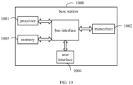
- FIG. 10 is a schematic structural diagram of a base station according to an embodiment of the present disclosure, which can implement details of the method for controlling activation of a bandwidth part (BWP) in the foregoing embodiments, and can achieve the same effects.
- the base station 1000 includes: a processor 1001, a transceiver 1002, a memory 1003, a user interface 1004, and a bus interface.
- the processor 1001 is configured to read a program in the memory 1003 and execute the following processes:
- a bus architecture may include any number of interconnected buses and bridges, and may be specifically configured to couple various circuits including one or more processors represented by the processor 1001 and storages represented by the memory 1003.
- the bus architecture may also couple various other circuits such as peripherals, voltage regulators and power management circuits, which are well known in the art. Therefore, a detailed description thereof is omitted herein.
- a bus interface provides an interface.
- the transceiver 1002 may be multiple elements, i.e., including a transmitter and a receiver, to allow for communication with various other apparatuses on the transmission medium.
- the user interface 1004 may also be an interface capable of may also be an interface capable of externally or internally connecting the required devices, which includes, but not limited to, a keypad, a display, a speaker, a microphone, a joystick, and the like.
- the processor 1001 is responsible for the control of the bus architecture and general processing, and the memory 1003 may store data used by the processor 300 in performing operations.
- the BWP configuration information is used to indicate a default BWP corresponding to each component carrier; and the program is executed by the processor 1001 to further perform the following steps: transmitting a component carrier activation-related signaling to the user equipment, where the component carrier activation-related signaling is used for the user equipment to activate a first target component carrier and a default BWP corresponding to the first target component carrier.
- the BWP configuration information indicates a default BWP corresponding to each component carrier as follows:
- the program is executed by the processor 1001 to further perform the following steps:
- the program is executed by the processor 1001 to further perform the following steps: transmitting a component carrier deactivation-related signaling to the user equipment, where the component carrier deactivation-related signaling is configured to instruct the user equipment to deactivate a third target component carrier, or to deactivate a third target component carrier and each of one or more activated BWPs on the third target component carrier.
- the BWP activation-related command is used for adjusting a deactivated BWP on a fourth target component carrier to an activated state; and the BWP activation-related command is used for instructing the user equipment to activate the fourth target component carrier and a BWP designated to be activated through the BWP activation-related command, in a case that the fourth target component carrier is in an inactive state.
- the BWP configuration information includes BWP configuration information of a primary base station and BWP configuration information of a secondary base station; and the BWP configuration information of the secondary base station is used to indicate a component carrier where a primary cell of the secondary base station is located, and default BWP information corresponding to each component carrier.
- the program is executed by the processor 1001 to further perform the following steps: transmitting a primary cell handover command to the user equipment, where the primary cell handover command is used for indicating a target primary cell as a handover cell and a default BWP on the target primary cell.
- BWP configuration information transmitted by a base station is received and saved, where the BWP configuration information includes BWP index information; a BWP activation-related command transmitted by the base station is received; and a BWP is activated based on a BWP index indicated by the BWP activation-related command.
- BWPs are numbered, the activation-related command indicates a BWP that needs to be activated, and the BWP is activated by a UE, thereby improving the flexibility of BWP activation control.
- An embodiment of the present disclosure further provides a computer-readable storage medium, having stored a computer program thereon.
- the computer program is executed by a processor to implements steps in a method for controlling activation of a bandwidth part (BWP) in any one of the foregoing method embodiments.
- BWP bandwidth part
- the disclosed device and method may be implemented in other manners.
- the described device embodiment is merely exemplary.
- the unit division is merely logical function division and may be other division in actual implementation.
- a plurality of units or components may be combined or integrated into another system, or some features may be neglected or not performed.
- the displayed or discussed mutual couplings or direct couplings or communication connections may be implemented through some interfaces.
- the indirect couplings or communication connections between the devices or units may be implemented in electric, mechanical, or other forms.
- the units described as separate parts may or may not be physically separate, and parts displayed as units may or may not be physical units, that is, may be located in one position, or may be distributed on a plurality of network units. A part or all of the units may be selected according to actual needs to achieve the objectives of the solutions of the embodiments of the present disclosure.
- the functions may be stored in a computer-readable storage medium.
- the software product is stored in a storage medium, and includes several instructions for instructing a computer device (which may be a personal computer, a server, or a network device) to perform all or a part of the steps of the methods described in the embodiments of the disclosure.
- the foregoing storage medium includes any medium that may store program code, such as a universal serial bus (USB) flash drive, a mobile hard disk, an ROM, an RAM, a magnetic disk, or an optical disc.
- USB universal serial bus
Landscapes
- Engineering & Computer Science (AREA)
- Signal Processing (AREA)
- Computer Networks & Wireless Communication (AREA)
- Mobile Radio Communication Systems (AREA)
Applications Claiming Priority (3)
| Application Number | Priority Date | Filing Date | Title |
|---|---|---|---|
| CN201710687870.4A CN109391444B (zh) | 2017-08-11 | 2017-08-11 | 一种bwp的激活控制方法、用户设备及基站 |
| EP18845117.3A EP3667994B1 (de) | 2017-08-11 | 2018-08-01 | Steuerungsverfahren für bwp aktivierung, benutzergerät und basisstation |
| PCT/CN2018/098001 WO2019029414A1 (zh) | 2017-08-11 | 2018-08-01 | Bwp的激活控制方法、用户设备及基站 |
Related Parent Applications (2)
| Application Number | Title | Priority Date | Filing Date |
|---|---|---|---|
| EP18845117.3A Division-Into EP3667994B1 (de) | 2017-08-11 | 2018-08-01 | Steuerungsverfahren für bwp aktivierung, benutzergerät und basisstation |
| EP18845117.3A Division EP3667994B1 (de) | 2017-08-11 | 2018-08-01 | Steuerungsverfahren für bwp aktivierung, benutzergerät und basisstation |
Publications (2)
| Publication Number | Publication Date |
|---|---|
| EP4412368A2 true EP4412368A2 (de) | 2024-08-07 |
| EP4412368A3 EP4412368A3 (de) | 2024-11-13 |
Family
ID=65273290
Family Applications (2)
| Application Number | Title | Priority Date | Filing Date |
|---|---|---|---|
| EP18845117.3A Active EP3667994B1 (de) | 2017-08-11 | 2018-08-01 | Steuerungsverfahren für bwp aktivierung, benutzergerät und basisstation |
| EP24183448.0A Pending EP4412368A3 (de) | 2017-08-11 | 2018-08-01 | Verfahren zur steuerung der aktivierung von bwp, benutzergerät und basisstation |
Family Applications Before (1)
| Application Number | Title | Priority Date | Filing Date |
|---|---|---|---|
| EP18845117.3A Active EP3667994B1 (de) | 2017-08-11 | 2018-08-01 | Steuerungsverfahren für bwp aktivierung, benutzergerät und basisstation |
Country Status (7)
| Country | Link |
|---|---|
| US (4) | US11212064B2 (de) |
| EP (2) | EP3667994B1 (de) |
| CN (3) | CN111756516B (de) |
| ES (1) | ES2985399T3 (de) |
| HU (1) | HUE068165T2 (de) |
| PT (1) | PT3667994T (de) |
| WO (1) | WO2019029414A1 (de) |
Families Citing this family (16)
| Publication number | Priority date | Publication date | Assignee | Title |
|---|---|---|---|---|
| US11716715B2 (en) * | 2017-07-28 | 2023-08-01 | Lg Electronics Inc. | Method of performing BWP operation in wireless communication system and an apparatus therefor |
| PL3493627T3 (pl) | 2017-09-14 | 2021-03-08 | Guangdong Oppo Mobile Telecommunications Corp., Ltd. | Metoda aktywacji części szerokości pasma (bwp) i produktu pokrewnego |
| WO2019061101A1 (zh) * | 2017-09-27 | 2019-04-04 | Oppo广东移动通信有限公司 | 一种小区激活和去激活方法、终端设备及计算机存储介质 |
| EP3528538B1 (de) | 2018-02-15 | 2021-08-18 | Panasonic Intellectual Property Corporation of America | Bandbreitenteilbetrieb während der übergabeprozedur |
| CN110536421B (zh) * | 2018-05-25 | 2022-05-10 | 华为技术有限公司 | 通信方法和装置 |
| CN110831177B (zh) * | 2018-08-10 | 2023-10-24 | 华为技术有限公司 | 去激活载波或激活载波的方法及装置 |
| CN109496454A (zh) * | 2018-10-17 | 2019-03-19 | 北京小米移动软件有限公司 | 带宽部分切换方法及装置 |
| CN111148237B (zh) * | 2018-11-02 | 2022-12-30 | 华为技术有限公司 | 一种通信方法及装置 |
| EP3930393B1 (de) * | 2019-02-22 | 2025-12-17 | Ntt Docomo, Inc. | Benutzervorrichtung und basisstationsvorrichtung |
| PT3845011T (pt) * | 2019-03-28 | 2023-09-27 | Ofinno Llc | Bwp ativa de poupança de energia |
| CN111867064B (zh) * | 2019-04-29 | 2023-08-04 | 华为技术有限公司 | 通信方法和装置 |
| CN111867012A (zh) * | 2019-04-30 | 2020-10-30 | 大唐移动通信设备有限公司 | 一种控制终端节能的方法、网络侧设备和终端 |
| US11432195B1 (en) * | 2020-03-27 | 2022-08-30 | T-Mobile Innovations Llc | Load balancing based on pairing efficiency and channel bandwidth |
| WO2021256985A1 (en) * | 2020-06-19 | 2021-12-23 | Telefonaktiebolaget Lm Ericsson (Publ) | Proactive radio access network configuration update |
| US11917689B2 (en) * | 2020-07-07 | 2024-02-27 | Qualcomm Incorporated | Redundancy version (RV) determination for message repetition |
| CN113922933B (zh) * | 2020-07-10 | 2023-01-06 | 维沃移动通信有限公司 | 一种载波切换处理方法、装置及终端 |
Family Cites Families (20)
| Publication number | Priority date | Publication date | Assignee | Title |
|---|---|---|---|---|
| CN101615984B (zh) | 2009-08-07 | 2013-03-27 | 中兴通讯股份有限公司 | 载波聚合下周期性cqi反馈的方法和装置 |
| CN102088433B (zh) * | 2009-12-08 | 2015-01-28 | 中兴通讯股份有限公司 | 多载波系统中分量载波激活去激活的优化方法和系统 |
| CN102149208B (zh) * | 2010-02-05 | 2013-11-06 | 华为技术有限公司 | 载波激活相关信息的处理方法、基站及ue |
| KR101507865B1 (ko) * | 2010-07-21 | 2015-04-07 | 엘지전자 주식회사 | 채널 상태 정보 피드백을 송수신하는 방법 및 그 장치 |
| US9673945B2 (en) | 2011-02-18 | 2017-06-06 | Qualcomm Incorporated | Implicitly linking aperiodic channel state information (A-CSI) reports to CSI-reference signal (CSI-RS) resources |
| US9559820B2 (en) * | 2011-02-18 | 2017-01-31 | Qualcomm Incorporated | Feedback reporting based on channel state information reference signal (CSI-RS) groups |
| EP3544219A1 (de) * | 2011-08-12 | 2019-09-25 | InterDigital Patent Holdings, Inc. | Betrieb mit flexibler bandbreite in drahtlosen systemen |
| CN103051645A (zh) * | 2011-10-11 | 2013-04-17 | 电子科技大学 | P2p网络中基于分组的激励机制 |
| CN102440051A (zh) * | 2011-10-27 | 2012-05-02 | 华为技术有限公司 | 分配多载波资源的方法、基站、和终端 |
| US20130114571A1 (en) | 2011-11-07 | 2013-05-09 | Qualcomm Incorporated | Coordinated forward link blanking and power boosting for flexible bandwidth systems |
| EP2733899B1 (de) * | 2012-09-27 | 2016-04-06 | Huawei Technologies Co., Ltd. | Verfahren und benutzergerät zur aktivierung bzw. deaktivierung von trägern |
| US10462771B2 (en) | 2013-04-04 | 2019-10-29 | Lg Electronics Inc. | Receiving method and user device in small-scale cell |
| CN104348525B (zh) * | 2013-07-31 | 2016-08-10 | 启碁科技股份有限公司 | 用于近场通信装置的传输装置及近场通信装置 |
| CN105099634B (zh) * | 2014-05-09 | 2019-05-07 | 中兴通讯股份有限公司 | 动态资源的分配方法及装置、基站、终端 |
| CN106100703B (zh) | 2016-06-16 | 2019-03-15 | 国网江苏省电力公司常州供电公司 | 电力计量现场检测数据蓝牙通讯方法 |
| ES2927069T3 (es) | 2016-12-27 | 2022-11-02 | 5G Ip Holdings Llc | Método para señalizar indicadores de parte de ancho de banda (BWP) y equipo de comunicación por radio que utiliza el mismo |
| CN110603778B (zh) * | 2017-05-05 | 2022-09-16 | 苹果公司 | 用于新无线电(nr)宽带用户设备(ue)的带宽部分配置和操作 |
| US10687365B2 (en) * | 2017-08-01 | 2020-06-16 | Htc Corporation | Device and method of handling bandwidth parts |
| EP3665849B1 (de) * | 2017-08-10 | 2024-05-01 | InterDigital Patent Holdings, Inc. | Verbesserte drx-verfahren für nr im verbundenen modus |
| CN110012512B (zh) * | 2018-01-04 | 2020-07-28 | 维沃移动通信有限公司 | 一种状态处理方法及相关设备 |
-
2017
- 2017-08-11 CN CN202010564585.5A patent/CN111756516B/zh active Active
- 2017-08-11 CN CN201710687870.4A patent/CN109391444B/zh active Active
- 2017-08-11 CN CN202010563896.XA patent/CN111740811B/zh active Active
-
2018
- 2018-08-01 EP EP18845117.3A patent/EP3667994B1/de active Active
- 2018-08-01 ES ES18845117T patent/ES2985399T3/es active Active
- 2018-08-01 PT PT188451173T patent/PT3667994T/pt unknown
- 2018-08-01 WO PCT/CN2018/098001 patent/WO2019029414A1/zh not_active Ceased
- 2018-08-01 HU HUE18845117A patent/HUE068165T2/hu unknown
- 2018-08-01 EP EP24183448.0A patent/EP4412368A3/de active Pending
- 2018-08-01 US US16/638,108 patent/US11212064B2/en active Active
-
2021
- 2021-11-14 US US17/525,925 patent/US11943175B2/en active Active
- 2021-11-14 US US17/525,924 patent/US11863499B2/en active Active
-
2024
- 2024-02-21 US US18/583,206 patent/US12301517B2/en active Active
Also Published As
| Publication number | Publication date |
|---|---|
| US11863499B2 (en) | 2024-01-02 |
| ES2985399T3 (es) | 2024-11-05 |
| CN111740811A (zh) | 2020-10-02 |
| CN111756516B (zh) | 2021-08-27 |
| EP3667994B1 (de) | 2024-07-24 |
| HUE068165T2 (hu) | 2024-12-28 |
| CN109391444B (zh) | 2020-07-07 |
| US20200244429A1 (en) | 2020-07-30 |
| EP3667994A1 (de) | 2020-06-17 |
| CN111756516A (zh) | 2020-10-09 |
| CN111740811B (zh) | 2021-08-24 |
| US11212064B2 (en) | 2021-12-28 |
| US20220078001A1 (en) | 2022-03-10 |
| EP3667994A4 (de) | 2020-08-05 |
| US20220078000A1 (en) | 2022-03-10 |
| US11943175B2 (en) | 2024-03-26 |
| WO2019029414A1 (zh) | 2019-02-14 |
| CN109391444A (zh) | 2019-02-26 |
| EP4412368A3 (de) | 2024-11-13 |
| US12301517B2 (en) | 2025-05-13 |
| US20240195595A1 (en) | 2024-06-13 |
| PT3667994T (pt) | 2024-08-26 |
Similar Documents
| Publication | Publication Date | Title |
|---|---|---|
| US12301517B2 (en) | Method for controlling activation of BWP, user equipment and base station | |
| US10869358B2 (en) | Configuration method of discountinuous reception parameter, mobile terminal, and base station | |
| CN108282280B (zh) | 一种参考信号的指示方法、网络设备及终端设备 | |
| EP3562049A1 (de) | Verfahren zur konfiguration und verarbeitung von strahlenverwaltungsinformationen, endgerät und basisstation | |
| EP3879755A1 (de) | Einstellungsverfahren zur verhinderung elektromagnetischer interferenz und zugehöriges produkt | |
| EP3641205A1 (de) | Kommunikationsverfahren, mobiles endgerät, basisstation und computerlesbares speichermedium | |
| US11546788B2 (en) | Configuration method and device of measurement reporting, measurement reporting method and device | |
| US20230156810A1 (en) | Information transmission method, base station, mobile terminal, and computer readable storage medium | |
| CN206559349U (zh) | 一种wifi射频电路及移动终端 | |
| CN108809547B (zh) | 一种数据传输方法、基站及终端 | |
| US10757692B2 (en) | Method for determining network standard in wireless communications network, access point device, terminal device, and radio network controller | |
| EP3672349B1 (de) | Direktzugriffsverfahren, endgerät und basisstation | |
| CN109151843B (zh) | 数据传输方法、移动终端、基站及计算机可读存储介质 | |
| EP3664339B1 (de) | Datenübertragungsverfahren sowie datendetektionsverfahren und -vorrichtung | |
| CN111211817A (zh) | 一种移动终端设备及多天线调试的方法 | |
| JP6281584B2 (ja) | 通信システム |
Legal Events
| Date | Code | Title | Description |
|---|---|---|---|
| PUAI | Public reference made under article 153(3) epc to a published international application that has entered the european phase |
Free format text: ORIGINAL CODE: 0009012 |
|
| STAA | Information on the status of an ep patent application or granted ep patent |
Free format text: STATUS: REQUEST FOR EXAMINATION WAS MADE |
|
| 17P | Request for examination filed |
Effective date: 20240620 |
|
| AC | Divisional application: reference to earlier application |
Ref document number: 3667994 Country of ref document: EP Kind code of ref document: P |
|
| AK | Designated contracting states |
Kind code of ref document: A2 Designated state(s): AL AT BE BG CH CY CZ DE DK EE ES FI FR GB GR HR HU IE IS IT LI LT LU LV MC MK MT NL NO PL PT RO RS SE SI SK SM TR |
|
| REG | Reference to a national code |
Ref country code: DE Ref legal event code: R079 Free format text: PREVIOUS MAIN CLASS: H04W0072040000 Ipc: H04L0005000000 |
|
| PUAL | Search report despatched |
Free format text: ORIGINAL CODE: 0009013 |
|
| AK | Designated contracting states |
Kind code of ref document: A3 Designated state(s): AL AT BE BG CH CY CZ DE DK EE ES FI FR GB GR HR HU IE IS IT LI LT LU LV MC MK MT NL NO PL PT RO RS SE SI SK SM TR |
|
| RIC1 | Information provided on ipc code assigned before grant |
Ipc: H04W 72/04 20230101ALI20241007BHEP Ipc: H04W 36/08 20090101ALI20241007BHEP Ipc: H04W 36/00 20090101ALI20241007BHEP Ipc: H04L 5/00 20060101AFI20241007BHEP |