EP4412248A1 - Ultrasonic sensor - Google Patents
Ultrasonic sensor Download PDFInfo
- Publication number
- EP4412248A1 EP4412248A1 EP22875684.7A EP22875684A EP4412248A1 EP 4412248 A1 EP4412248 A1 EP 4412248A1 EP 22875684 A EP22875684 A EP 22875684A EP 4412248 A1 EP4412248 A1 EP 4412248A1
- Authority
- EP
- European Patent Office
- Prior art keywords
- elastic member
- vibration body
- ultrasonic sensor
- housing
- vibration
- Prior art date
- Legal status (The legal status is an assumption and is not a legal conclusion. Google has not performed a legal analysis and makes no representation as to the accuracy of the status listed.)
- Pending
Links
Images


Classifications
-
- G—PHYSICS
- G01—MEASURING; TESTING
- G01S—RADIO DIRECTION-FINDING; RADIO NAVIGATION; DETERMINING DISTANCE OR VELOCITY BY USE OF RADIO WAVES; LOCATING OR PRESENCE-DETECTING BY USE OF THE REFLECTION OR RERADIATION OF RADIO WAVES; ANALOGOUS ARRANGEMENTS USING OTHER WAVES
- G01S7/00—Details of systems according to groups G01S13/00, G01S15/00, G01S17/00
- G01S7/52—Details of systems according to groups G01S13/00, G01S15/00, G01S17/00 of systems according to group G01S15/00
- G01S7/521—Constructional features
-
- B—PERFORMING OPERATIONS; TRANSPORTING
- B06—GENERATING OR TRANSMITTING MECHANICAL VIBRATIONS IN GENERAL
- B06B—METHODS OR APPARATUS FOR GENERATING OR TRANSMITTING MECHANICAL VIBRATIONS OF INFRASONIC, SONIC, OR ULTRASONIC FREQUENCY, e.g. FOR PERFORMING MECHANICAL WORK IN GENERAL
- B06B1/00—Methods or apparatus for generating mechanical vibrations of infrasonic, sonic, or ultrasonic frequency
- B06B1/02—Methods or apparatus for generating mechanical vibrations of infrasonic, sonic, or ultrasonic frequency making use of electrical energy
- B06B1/06—Methods or apparatus for generating mechanical vibrations of infrasonic, sonic, or ultrasonic frequency making use of electrical energy operating with piezoelectric effect or with electrostriction
- B06B1/0644—Methods or apparatus for generating mechanical vibrations of infrasonic, sonic, or ultrasonic frequency making use of electrical energy operating with piezoelectric effect or with electrostriction using a single piezoelectric element
-
- G—PHYSICS
- G01—MEASURING; TESTING
- G01S—RADIO DIRECTION-FINDING; RADIO NAVIGATION; DETERMINING DISTANCE OR VELOCITY BY USE OF RADIO WAVES; LOCATING OR PRESENCE-DETECTING BY USE OF THE REFLECTION OR RERADIATION OF RADIO WAVES; ANALOGOUS ARRANGEMENTS USING OTHER WAVES
- G01S15/00—Systems using the reflection or reradiation of acoustic waves, e.g. sonar systems
- G01S15/88—Sonar systems specially adapted for specific applications
- G01S15/93—Sonar systems specially adapted for specific applications for anti-collision purposes
- G01S15/931—Sonar systems specially adapted for specific applications for anti-collision purposes of land vehicles
-
- G—PHYSICS
- G10—MUSICAL INSTRUMENTS; ACOUSTICS
- G10K—SOUND-PRODUCING DEVICES; METHODS OR DEVICES FOR PROTECTING AGAINST, OR FOR DAMPING, NOISE OR OTHER ACOUSTIC WAVES IN GENERAL; ACOUSTICS NOT OTHERWISE PROVIDED FOR
- G10K9/00—Devices in which sound is produced by vibrating a diaphragm or analogous element, e.g. fog horns, vehicle hooters or buzzers
- G10K9/12—Devices in which sound is produced by vibrating a diaphragm or analogous element, e.g. fog horns, vehicle hooters or buzzers electrically operated
- G10K9/122—Devices in which sound is produced by vibrating a diaphragm or analogous element, e.g. fog horns, vehicle hooters or buzzers electrically operated using piezoelectric driving means
-
- G—PHYSICS
- G10—MUSICAL INSTRUMENTS; ACOUSTICS
- G10K—SOUND-PRODUCING DEVICES; METHODS OR DEVICES FOR PROTECTING AGAINST, OR FOR DAMPING, NOISE OR OTHER ACOUSTIC WAVES IN GENERAL; ACOUSTICS NOT OTHERWISE PROVIDED FOR
- G10K9/00—Devices in which sound is produced by vibrating a diaphragm or analogous element, e.g. fog horns, vehicle hooters or buzzers
- G10K9/18—Details, e.g. bulbs, pumps, pistons, switches or casings
- G10K9/22—Mountings; Casings
-
- H—ELECTRICITY
- H04—ELECTRIC COMMUNICATION TECHNIQUE
- H04R—LOUDSPEAKERS, MICROPHONES, GRAMOPHONE PICK-UPS OR LIKE ACOUSTIC ELECTROMECHANICAL TRANSDUCERS; ELECTRIC HEARING AIDS; PUBLIC ADDRESS SYSTEMS
- H04R17/00—Piezoelectric transducers; Electrostrictive transducers
-
- B—PERFORMING OPERATIONS; TRANSPORTING
- B06—GENERATING OR TRANSMITTING MECHANICAL VIBRATIONS IN GENERAL
- B06B—METHODS OR APPARATUS FOR GENERATING OR TRANSMITTING MECHANICAL VIBRATIONS OF INFRASONIC, SONIC, OR ULTRASONIC FREQUENCY, e.g. FOR PERFORMING MECHANICAL WORK IN GENERAL
- B06B1/00—Methods or apparatus for generating mechanical vibrations of infrasonic, sonic, or ultrasonic frequency
- B06B1/02—Methods or apparatus for generating mechanical vibrations of infrasonic, sonic, or ultrasonic frequency making use of electrical energy
- B06B1/06—Methods or apparatus for generating mechanical vibrations of infrasonic, sonic, or ultrasonic frequency making use of electrical energy operating with piezoelectric effect or with electrostriction
- B06B1/0644—Methods or apparatus for generating mechanical vibrations of infrasonic, sonic, or ultrasonic frequency making use of electrical energy operating with piezoelectric effect or with electrostriction using a single piezoelectric element
- B06B1/0648—Methods or apparatus for generating mechanical vibrations of infrasonic, sonic, or ultrasonic frequency making use of electrical energy operating with piezoelectric effect or with electrostriction using a single piezoelectric element of rectangular shape
-
- B—PERFORMING OPERATIONS; TRANSPORTING
- B06—GENERATING OR TRANSMITTING MECHANICAL VIBRATIONS IN GENERAL
- B06B—METHODS OR APPARATUS FOR GENERATING OR TRANSMITTING MECHANICAL VIBRATIONS OF INFRASONIC, SONIC, OR ULTRASONIC FREQUENCY, e.g. FOR PERFORMING MECHANICAL WORK IN GENERAL
- B06B1/00—Methods or apparatus for generating mechanical vibrations of infrasonic, sonic, or ultrasonic frequency
- B06B1/02—Methods or apparatus for generating mechanical vibrations of infrasonic, sonic, or ultrasonic frequency making use of electrical energy
- B06B1/06—Methods or apparatus for generating mechanical vibrations of infrasonic, sonic, or ultrasonic frequency making use of electrical energy operating with piezoelectric effect or with electrostriction
- B06B1/0644—Methods or apparatus for generating mechanical vibrations of infrasonic, sonic, or ultrasonic frequency making use of electrical energy operating with piezoelectric effect or with electrostriction using a single piezoelectric element
- B06B1/0651—Methods or apparatus for generating mechanical vibrations of infrasonic, sonic, or ultrasonic frequency making use of electrical energy operating with piezoelectric effect or with electrostriction using a single piezoelectric element of circular shape
-
- B—PERFORMING OPERATIONS; TRANSPORTING
- B06—GENERATING OR TRANSMITTING MECHANICAL VIBRATIONS IN GENERAL
- B06B—METHODS OR APPARATUS FOR GENERATING OR TRANSMITTING MECHANICAL VIBRATIONS OF INFRASONIC, SONIC, OR ULTRASONIC FREQUENCY, e.g. FOR PERFORMING MECHANICAL WORK IN GENERAL
- B06B1/00—Methods or apparatus for generating mechanical vibrations of infrasonic, sonic, or ultrasonic frequency
- B06B1/02—Methods or apparatus for generating mechanical vibrations of infrasonic, sonic, or ultrasonic frequency making use of electrical energy
- B06B1/06—Methods or apparatus for generating mechanical vibrations of infrasonic, sonic, or ultrasonic frequency making use of electrical energy operating with piezoelectric effect or with electrostriction
- B06B1/0644—Methods or apparatus for generating mechanical vibrations of infrasonic, sonic, or ultrasonic frequency making use of electrical energy operating with piezoelectric effect or with electrostriction using a single piezoelectric element
- B06B1/0655—Methods or apparatus for generating mechanical vibrations of infrasonic, sonic, or ultrasonic frequency making use of electrical energy operating with piezoelectric effect or with electrostriction using a single piezoelectric element of cylindrical shape
-
- G—PHYSICS
- G01—MEASURING; TESTING
- G01S—RADIO DIRECTION-FINDING; RADIO NAVIGATION; DETERMINING DISTANCE OR VELOCITY BY USE OF RADIO WAVES; LOCATING OR PRESENCE-DETECTING BY USE OF THE REFLECTION OR RERADIATION OF RADIO WAVES; ANALOGOUS ARRANGEMENTS USING OTHER WAVES
- G01S15/00—Systems using the reflection or reradiation of acoustic waves, e.g. sonar systems
- G01S15/88—Sonar systems specially adapted for specific applications
- G01S15/93—Sonar systems specially adapted for specific applications for anti-collision purposes
- G01S15/931—Sonar systems specially adapted for specific applications for anti-collision purposes of land vehicles
- G01S2015/937—Sonar systems specially adapted for specific applications for anti-collision purposes of land vehicles sensor installation details
- G01S2015/938—Sonar systems specially adapted for specific applications for anti-collision purposes of land vehicles sensor installation details in the bumper area
-
- H—ELECTRICITY
- H10—SEMICONDUCTOR DEVICES; ELECTRIC SOLID-STATE DEVICES NOT OTHERWISE PROVIDED FOR
- H10N—ELECTRIC SOLID-STATE DEVICES NOT OTHERWISE PROVIDED FOR
- H10N30/00—Piezoelectric or electrostrictive devices
- H10N30/80—Constructional details
- H10N30/88—Mounts; Supports; Enclosures; Casings
Definitions
- the present invention relates to an ultrasonic sensor.
- the ultrasonic sensor described in Patent Document 1 includes an ultrasonic transducer.
- the ultrasonic transducer includes a housing having a cylindrical shape with a bottom, a piezoelectric element fixed to a bottom portion of the housing, and a base fixed to an opening of the housing with a spacer interposed therebetween.
- the spacer is made of an elastic body.
- the housing includes the bottom portion and a cylindrical portion.
- the spacer is an elastic body that prevents unnecessary vibration, caused by vibration of the bottom portion, generated in the cylindrical portion from being transferred to the base.
- Such an ultrasonic transducer is covered with a cylindrical elastic body, and a foamed elastic body is disposed on a lower side of the base as an elastic body that suppresses vibration.
- Patent Document 1 Japanese Patent No. 4438667
- the spacer of Patent Document 1 has a rib shape, and an outer surface of the rib shape is exposed to an outer peripheral surface of the ultrasonic transducer so as to hinder vibration transfer. Since the spacer has a front and rear asymmetrical shape, attention is required during assembly so as not to make a mistake in arranging the front and the rear.
- Patent Document 1 describes that the spacer is made of, for example, silicon rubber.
- a spacer has a large specific gravity, and does not have a sufficient effect of hindering vibration transfer.
- fluctuation in the frequency of unnecessary vibration and variation in the product characteristics may be caused.
- an object of the present invention is to provide an ultrasonic sensor of which the assembly operation is facilitated and which can suppress unnecessary vibration transfer as much as possible.
- an ultrasonic sensor based on the present invention includes a vibration body including a cylindrical portion and a bottom portion that closes one end of the cylindrical portion, a piezoelectric element fixed to an inner surface of the bottom portion of the vibration body, a first housing member that constitutes at least a part of a housing storing the vibration body, and a first elastic member that is disposed while being interposed between the vibration body and the first housing member.
- the first elastic member has a front and rear symmetrical shape and includes a closed-cell structure.
- the first elastic member that is disposed while being interposed between the vibration body and the first housing member has a front and rear symmetrical shape and includes a closed-cell structure, an ultrasonic sensor of which the assembly operation is facilitated and which can suppress unnecessary vibration transfer as much as possible can be achieved.
- Fig. 1 illustrates an ultrasonic sensor 101 according to the present embodiment.
- Fig. 2 illustrates an exploded view of the ultrasonic sensor 101.
- the ultrasonic sensor 101 includes a rear cover 6, a wiring board assembly 7, a first filling member 8, a second filling member 9, wiring 10, a first housing member 51, a first elastic member 4, a vibration body 2, a second elastic member 5, and a second housing member 52.
- the first elastic member 4 includes a closed-cell structure.
- the vibration body 2 has a cylindrical shape with a bottom.
- the vibration body 2 is made of, for example, metal.
- the metal is, for example, aluminum.
- the vibration body 2 includes a bottom portion 2a, a cylindrical portion 2b, and a flange portion 2c.
- the first housing member 51 and the second housing member 52 are made of, for example, resin.
- the material of the first housing member 51 and the second housing member 52 may be the same kind.
- the rear cover 6 may be made of, for example, resin.
- the first filling member 8 is made of, for example, foamed silicone.
- the second filling member 9 is, for example, a silicone member disposed by potting processing.
- the second elastic member 5 is made of, for example, rubber.
- a piezoelectric element 1 is disposed inside the vibration body 2.
- the piezoelectric element 1 is attached to an inner surface of the bottom portion 2a with an adhesive sheet 3 interposed therebetween.
- the adhesive sheet 3 may be a double-sided tape.
- Fig. 4 illustrates the ultrasonic sensor 101 in an orientation in which the rear cover 6 faces up.
- the orientation illustrated in Fig. 4 corresponds to a state in which the ultrasonic sensor 101 illustrated in Fig. 1 is inverted in an up-and-down direction.
- Fig. 5 is a cross-sectional view taken along an arrow line V-V in Fig. 4 .
- Fig. 6 is a cross-sectional view taken along an arrow line VI-VI in Fig. 4 .
- the rear cover 6, the wiring board assembly 7, the wiring 10, the adhesive sheet 3, and the like are not illustrated.
- the first elastic member 4 is interposed between the vibration body 2 and the first housing member 51.
- the first filling member 8 is disposed inside the vibration body 2 so as to be in contact with the piezoelectric element 1 and the bottom portion 2a.
- the second filling member 9 is disposed so as to cover the first filling member 8. A part of the second filling member 9 protrudes to the outside from the internal space of the vibration body 2.
- the first elastic member 4 has an annular shape. That is, the first elastic member 4 has an opening.
- the second filling member 9 penetrates the opening of the first elastic member 4.
- Fig. 7 illustrates a portion illustrated in Fig. 5 in a state in which the first filling member 8 and the second filling member 9 are removed.
- Fig. 8 illustrates a portion illustrated in Fig. 6 in a state in which the first filling member 8 and the second filling member 9 are removed.
- Fig. 9 is an exploded view of some components of a component group illustrated in Fig. 2 when viewed in a different direction.
- Fig. 9 illustrates the first housing member 51, the first elastic member 4, the vibration body 2, the second elastic member 5, and the second housing member 52.
- Fig 10 illustrates a state in which the above-described components are assembled halfway.
- Fig. 10 also illustrates the piezoelectric element 1 attached to the inner surface of the vibration body 2.
- Fig. 11 illustrates a state in which the vibration body 2, the second elastic member 5, and the second housing member 52 are assembled.
- Fig. 12 illustrates a state in which the first elastic member 4 is further assembled in a portion illustrated in Fig. 11
- the configuration of the ultrasonic sensor 101 can be expressed as described below, for example.
- the ultrasonic sensor 101 includes the vibration body 2 including the cylindrical portion 2b and the bottom portion 2a that closes one end of the cylindrical portion 2b, the piezoelectric element 1 fixed to an inner surface of the bottom portion 2a of the vibration body 2, the first housing member 51 that constitutes at least a part of a housing storing the vibration body 2, and the first elastic member 4 that is disposed while being interposed between the vibration body 2 and the first housing member 51.
- the first elastic member 4 has a front and rear symmetrical shape and includes a closed-cell structure.
- the ultrasonic sensor 101 since the ultrasonic sensor 101 includes the first elastic member 4 that is disposed while being interposed between the vibration body 2 and the first housing member 51, and the first elastic member 4 includes a closed-cell structure, vibration transfer from the vibration body 2 to the first housing member 51 can be more effectively hindered. That is, unnecessary vibration transfer can be suppressed as much as possible.
- the first elastic member 4 since the first elastic member 4 has a front and rear symmetrical shape, assembly operation can be performed without paying attention to distinction between the front and the rear. Therefore, the assembly operation is facilitated,
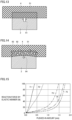
- FIG. 13 With reference to Figs. 13 and 14 , advantages of the first elastic member 4 including a closed-cell structure will be described.
- the structure is schematically illustrated.
- the first elastic member 4 is interposed between the first housing member 51 and the vibration body 2, and it is assumed that when the vibration body 2 vibrates, an upper surface of the vibration body 2 is largely displaced upward as indicated by an arrow 91.
- a lower surface of the first elastic member 4 is pushed and is displaced so as to enter the inside of the first elastic member 4, thereby acting in a direction of reducing the volume of the first elastic member 4.
- the first elastic member 4 is made of rubber, the first elastic member 4 has a fixed Poisson ratio, and thus when the lower surface of the first elastic member 4 is pushed in, an upper surface and an outer peripheral surface of the first elastic member 4 is pushed out from the original surfaces by the amount corresponding to the volume pushed in. As a result, the first housing member 51 is pushed and displaced. When such displacement is repeated, vibration is transferred to the first housing member 51.
- the first elastic member 4 when the first elastic member 4 includes a closed-cell structure, each of the closed cells inside the first elastic member 4 can be compressed and contracted. Therefore, the imposed volume change is absorbed to some extent by the closed cells. As a result, as illustrated by arrows 92 and 93 in Fig. 14 , the pushing force of the upper surface and the outer peripheral surface of the first elastic member 4 from the original surfaces toward outside is decreased. Therefore, the amount of displacement of the first housing member 51 being pushed is also reduced. As a result, the degree of vibration transfer to the first housing member 51 can be reduced.
- Fig. 15 is a graph indicating the magnitude of a reaction force generated around an elastic member with respect to a pushed-in amount given to the elastic member.
- a curved line 71 indicates a case in which rubber having a hardness of 50 is used as the elastic member.
- a curved line 72 indicates a case in which rubber having a hardness of 30 is used as the elastic member.
- a curved line 73 indicates a case in which sponge having a hardness of 30 is used as the elastic member.
- a curved line 74 indicates a case in which sponge having a hardness of 20 is used as the elastic member.
- a curved line 75 indicates a case in which sponge having a hardness of 15 is used as the elastic member.
- the hardness of rubber is measured by a type A durometer (Asker A type) conforming to JIS K6253-3.
- the hardness of sponge is measured by a type E durometer (Asker C type) conforming to JIS K6253-3.
- JIS K6253-3 of the JIS standard corresponds to ISO 48-4 of the ISO standard.
- the curved lines 71 and 72 correspond to a case in which a member not including a closed-cell structure is used, and the curved lines 73, 74, and 75 correspond to a case in which a member including a closed-cell structure is used.
- reaction forces of the curved lines 73, 74, and 75 tend to be suppressed small even with respect to the same pushed-in amount.
- the reaction forces being suppressed small means that unnecessary vibration transfer is easily suppressed.
- a member including closed cells does not easily allow water or the like to pass therethrough, compared to a member including open cells, and thus has high waterproof capability.
- the member includes open cells, since air passes through the member, pickup by vacuum suction is difficult to perform, but when the member includes closed cells, since air does not pass through the member, pickup by vacuum suction is easily performed.
- the first elastic member 4 is preferably a member including closed cells so that entry of the liquid material into the first elastic member 4 can be avoided.
- the inventor observes a state of reverberation in a case in which the Asker hardness, which is a hardness of sponge, is 10, and in a case in which the Asker hardness is 30. That is, the inventor drives the piezoelectric element 1 and vibrates the vibration body 2 only for a fixed time, and observes the vibration remaining when the piezoelectric element 1 is stopped thereafter, that is, the reverberation. As a result, the inventor confirms that the reverberation is suppressed small in the case in which the Asker hardness is 10, compared to the case in which the Asker hardness is 30.
- the inventor performs an experiment to measure a reverberation time at a low temperature related to the respective first elastic members 4 having a hardness of 10, 15, and 20. It is discovered that although the elastic member is hardened at a low temperature, the state of a reaction force being small can be maintained, and the function of hindering vibration transfer is excellent.
- the inventor performs an experiment by changing the thickness of the first elastic member 4 to several different thicknesses. Assuming that there is a gap of 0.85 mm, the inventor disposes the first elastic member 4 in the gap in a compressed state and measures various characteristics of a sensor, but little influence is shown in the characteristics by the difference in thickness. Therefore, a rough design can be made, that is, design tolerance can be eased. Since the first elastic member 4 including closed cells is lightweight compared to rubber or the like, the degree of influence on a frequency is very small.
- the vibration body 2 preferably includes the flange portion 2c, and the first elastic member 4 is preferably in contact with the flange portion 2c.
- the first elastic member 4 can stably support the vibration body 2.
- the degree of transfer of unnecessary vibration to other members from the vibration body 2 can be reduced by the first elastic member 4.
- the first elastic member 4 is preferably a member having an annular shape with a fixed thickness. Through adopting of this configuration, the vibration body 2 can be easily uniformly supported.
- the first elastic member 4 may be formed, for example, through punching of a plate material with a fixed thickness.
- the first elastic member 4 is preferably made of at least one material selected from the group consisting of silicone, modified silicone, and urethane. Through adopting of this configuration, unnecessary vibration transfer can be effectively suppressed.
- the first elastic member 4 is formed through performing of a foam treatment in which a closed-cell structure can be formed in a material that satisfies the above-described conditions.
Landscapes
- Engineering & Computer Science (AREA)
- Physics & Mathematics (AREA)
- Radar, Positioning & Navigation (AREA)
- Remote Sensing (AREA)
- Acoustics & Sound (AREA)
- Computer Networks & Wireless Communication (AREA)
- General Physics & Mathematics (AREA)
- Mechanical Engineering (AREA)
- Multimedia (AREA)
- Signal Processing (AREA)
- Transducers For Ultrasonic Waves (AREA)
- Measurement Of Velocity Or Position Using Acoustic Or Ultrasonic Waves (AREA)
Abstract
Description
- The present invention relates to an ultrasonic sensor.
- An example of an ultrasonic sensor is described in
Japanese Patent No. 4438667 Patent Document 1 includes an ultrasonic transducer. The ultrasonic transducer includes a housing having a cylindrical shape with a bottom, a piezoelectric element fixed to a bottom portion of the housing, and a base fixed to an opening of the housing with a spacer interposed therebetween. The spacer is made of an elastic body. The housing includes the bottom portion and a cylindrical portion. The spacer is an elastic body that prevents unnecessary vibration, caused by vibration of the bottom portion, generated in the cylindrical portion from being transferred to the base. Such an ultrasonic transducer is covered with a cylindrical elastic body, and a foamed elastic body is disposed on a lower side of the base as an elastic body that suppresses vibration. - Patent Document 1:
Japanese Patent No. 4438667 - The spacer of
Patent Document 1 has a rib shape, and an outer surface of the rib shape is exposed to an outer peripheral surface of the ultrasonic transducer so as to hinder vibration transfer. Since the spacer has a front and rear asymmetrical shape, attention is required during assembly so as not to make a mistake in arranging the front and the rear. -
Patent Document 1 describes that the spacer is made of, for example, silicon rubber. However, such a spacer has a large specific gravity, and does not have a sufficient effect of hindering vibration transfer. When such a spacer is in contact with the housing, fluctuation in the frequency of unnecessary vibration and variation in the product characteristics may be caused. - Therefore, an object of the present invention is to provide an ultrasonic sensor of which the assembly operation is facilitated and which can suppress unnecessary vibration transfer as much as possible.
- In order to achieve the above-described object, an ultrasonic sensor based on the present invention includes a vibration body including a cylindrical portion and a bottom portion that closes one end of the cylindrical portion, a piezoelectric element fixed to an inner surface of the bottom portion of the vibration body, a first housing member that constitutes at least a part of a housing storing the vibration body, and a first elastic member that is disposed while being interposed between the vibration body and the first housing member. The first elastic member has a front and rear symmetrical shape and includes a closed-cell structure.
- According to the present invention, since the first elastic member that is disposed while being interposed between the vibration body and the first housing member has a front and rear symmetrical shape and includes a closed-cell structure, an ultrasonic sensor of which the assembly operation is facilitated and which can suppress unnecessary vibration transfer as much as possible can be achieved. Brief Description of Drawings
-
- [
Fig. 1] Fig. 1 is a first perspective view of an ultrasonic sensor according to a first embodiment based on the present invention. - [
Fig. 2] Fig. 2 is an exploded view of the ultrasonic sensor according to the first embodiment based on the present invention. - [
Fig. 3] Fig. 3 is an exploded view related to a vibration body included in the ultrasonic sensor according to the first embodiment based on the present invention. - [
Fig. 4] Fig. 4 is a second perspective view of the ultrasonic sensor according to the first embodiment based on the present invention. - [
Fig. 5] Fig. 5 is a cross-sectional view taken along an arrow line V-V inFig. 4 . - [
Fig. 6] Fig. 6 is a cross-sectional view taken along an arrow line VI-VI inFig. 4 . - [
Fig. 7] Fig. 7 is a cross-sectional view of a portion illustrated inFig. 5 in a state in which a first filling member and a second filling member are removed. - [
Fig. 8] Fig. 8 is a cross-sectional view of a portion illustrated inFig. 6 in a state in which the first filling member and the second filling member are removed. - [
Fig. 9] Fig. 9 is an exploded view of some components of a component group illustrated inFig. 2 when viewed in a different direction. - [
Fig. 10] Fig. 10 is an exploded view of a component group illustrated inFig. 9 in a state of being assembled halfway. - [
Fig. 11] Fig. 11 is a perspective view of a state in which the vibration body, a second elastic member, and a second housing member included in the ultrasonic sensor according to the first embodiment based on the present invention are assembled. - [
Fig. 12] Fig. 12 is a perspective view of a state in which a firstelastic member 4 is assembled in a portion illustrated inFig. 11 . - [
Fig. 13] Fig. 13 is a first explanatory diagram for illustrating advantages of the first elastic member including a closed-cell structure. - [
Fig. 14] Fig. 14 is a second explanatory diagram for illustrating advantages of the first elastic member including a closed-cell structure. - [
Fig. 15] Fig. 15 is a graph indicating magnitude of a reaction force generated around an elastic member with respect to a pushed-in amount given to the elastic member. Description of Embodiments - The dimensional ratios illustrated in the drawings do not always faithfully represent the actual dimensional ratios, and the dimensional ratios may be exaggerated for convenience of description. In the following description, when referring to the concept of above or below, it does not necessarily mean absolute above or below, but may mean relative above or below in the illustrated positions.
- With reference to
Figs. 1 to 12 , an ultrasonic sensor according to a first embodiment based on the present invention will be described.Fig. 1 illustrates anultrasonic sensor 101 according to the present embodiment.Fig. 2 illustrates an exploded view of theultrasonic sensor 101. Theultrasonic sensor 101 includes arear cover 6, awiring board assembly 7, afirst filling member 8, asecond filling member 9,wiring 10, afirst housing member 51, a firstelastic member 4, avibration body 2, a secondelastic member 5, and asecond housing member 52. The firstelastic member 4 includes a closed-cell structure. Thevibration body 2 has a cylindrical shape with a bottom. Thevibration body 2 is made of, for example, metal. Here, the metal is, for example, aluminum. Thevibration body 2 includes abottom portion 2a, acylindrical portion 2b, and aflange portion 2c. Thefirst housing member 51 and thesecond housing member 52 are made of, for example, resin. The material of thefirst housing member 51 and thesecond housing member 52 may be the same kind. Therear cover 6 may be made of, for example, resin. The first fillingmember 8 is made of, for example, foamed silicone. The second fillingmember 9 is, for example, a silicone member disposed by potting processing. The secondelastic member 5 is made of, for example, rubber. - As illustrated in
Fig. 3 , apiezoelectric element 1 is disposed inside thevibration body 2. Thepiezoelectric element 1 is attached to an inner surface of thebottom portion 2a with anadhesive sheet 3 interposed therebetween. Theadhesive sheet 3 may be a double-sided tape. -
Fig. 4 illustrates theultrasonic sensor 101 in an orientation in which therear cover 6 faces up. The orientation illustrated inFig. 4 corresponds to a state in which theultrasonic sensor 101 illustrated inFig. 1 is inverted in an up-and-down direction.Fig. 5 is a cross-sectional view taken along an arrow line V-V inFig. 4 .Fig. 6 is a cross-sectional view taken along an arrow line VI-VI inFig. 4 . InFigs. 5 and6 , therear cover 6, thewiring board assembly 7, thewiring 10, theadhesive sheet 3, and the like are not illustrated. - The first
elastic member 4 is interposed between thevibration body 2 and thefirst housing member 51. Thefirst filling member 8 is disposed inside thevibration body 2 so as to be in contact with thepiezoelectric element 1 and thebottom portion 2a. Moreover, thesecond filling member 9 is disposed so as to cover the first fillingmember 8. A part of thesecond filling member 9 protrudes to the outside from the internal space of thevibration body 2. The firstelastic member 4 has an annular shape. That is, the firstelastic member 4 has an opening. Thesecond filling member 9 penetrates the opening of the firstelastic member 4.Fig. 7 illustrates a portion illustrated inFig. 5 in a state in which the first fillingmember 8 and thesecond filling member 9 are removed.Fig. 8 illustrates a portion illustrated inFig. 6 in a state in which the first fillingmember 8 and thesecond filling member 9 are removed. -
Fig. 9 is an exploded view of some components of a component group illustrated inFig. 2 when viewed in a different direction.Fig. 9 illustrates thefirst housing member 51, the firstelastic member 4, thevibration body 2, the secondelastic member 5, and thesecond housing member 52.Fig 10 illustrates a state in which the above-described components are assembled halfway.Fig. 10 also illustrates thepiezoelectric element 1 attached to the inner surface of thevibration body 2.Fig. 11 illustrates a state in which thevibration body 2, the secondelastic member 5, and thesecond housing member 52 are assembled.Fig. 12 illustrates a state in which the firstelastic member 4 is further assembled in a portion illustrated inFig. 11 - The configuration of the
ultrasonic sensor 101 can be expressed as described below, for example. Theultrasonic sensor 101 includes thevibration body 2 including thecylindrical portion 2b and thebottom portion 2a that closes one end of thecylindrical portion 2b, thepiezoelectric element 1 fixed to an inner surface of thebottom portion 2a of thevibration body 2, thefirst housing member 51 that constitutes at least a part of a housing storing thevibration body 2, and the firstelastic member 4 that is disposed while being interposed between thevibration body 2 and thefirst housing member 51. The firstelastic member 4 has a front and rear symmetrical shape and includes a closed-cell structure. - In the present embodiment, since the
ultrasonic sensor 101 includes the firstelastic member 4 that is disposed while being interposed between thevibration body 2 and thefirst housing member 51, and the firstelastic member 4 includes a closed-cell structure, vibration transfer from thevibration body 2 to thefirst housing member 51 can be more effectively hindered. That is, unnecessary vibration transfer can be suppressed as much as possible. In addition, since the firstelastic member 4 has a front and rear symmetrical shape, assembly operation can be performed without paying attention to distinction between the front and the rear. Therefore, the assembly operation is facilitated, - With reference to
Figs. 13 and 14 , advantages of the firstelastic member 4 including a closed-cell structure will be described. InFigs. 13 and 14 , for convenience of description, the structure is schematically illustrated. As illustrated inFig. 13 , the firstelastic member 4 is interposed between thefirst housing member 51 and thevibration body 2, and it is assumed that when thevibration body 2 vibrates, an upper surface of thevibration body 2 is largely displaced upward as indicated by anarrow 91. As a result, a lower surface of the firstelastic member 4 is pushed and is displaced so as to enter the inside of the firstelastic member 4, thereby acting in a direction of reducing the volume of the firstelastic member 4. - If the first
elastic member 4 is made of rubber, the firstelastic member 4 has a fixed Poisson ratio, and thus when the lower surface of the firstelastic member 4 is pushed in, an upper surface and an outer peripheral surface of the firstelastic member 4 is pushed out from the original surfaces by the amount corresponding to the volume pushed in. As a result, thefirst housing member 51 is pushed and displaced. When such displacement is repeated, vibration is transferred to thefirst housing member 51. - However, when the first
elastic member 4 includes a closed-cell structure, each of the closed cells inside the firstelastic member 4 can be compressed and contracted. Therefore, the imposed volume change is absorbed to some extent by the closed cells. As a result, as illustrated by arrows 92 and 93 inFig. 14 , the pushing force of the upper surface and the outer peripheral surface of the firstelastic member 4 from the original surfaces toward outside is decreased. Therefore, the amount of displacement of thefirst housing member 51 being pushed is also reduced. As a result, the degree of vibration transfer to thefirst housing member 51 can be reduced. -
Fig. 15 is a graph indicating the magnitude of a reaction force generated around an elastic member with respect to a pushed-in amount given to the elastic member. InFig. 15 , acurved line 71 indicates a case in which rubber having a hardness of 50 is used as the elastic member. Acurved line 72 indicates a case in which rubber having a hardness of 30 is used as the elastic member. A curved line 73 indicates a case in which sponge having a hardness of 30 is used as the elastic member. Acurved line 74 indicates a case in which sponge having a hardness of 20 is used as the elastic member. Acurved line 75 indicates a case in which sponge having a hardness of 15 is used as the elastic member. The hardness of rubber is measured by a type A durometer (Asker A type) conforming to JIS K6253-3. The hardness of sponge is measured by a type E durometer (Asker C type) conforming to JIS K6253-3. JIS K6253-3 of the JIS standard corresponds to ISO 48-4 of the ISO standard. Thecurved lines curved lines - As illustrated in
Fig. 15 , compared to thecurved lines curved lines - Note that a member including closed cells does not easily allow water or the like to pass therethrough, compared to a member including open cells, and thus has high waterproof capability. When the member includes open cells, since air passes through the member, pickup by vacuum suction is difficult to perform, but when the member includes closed cells, since air does not pass through the member, pickup by vacuum suction is easily performed.
- In addition, when the first filling
member 8 and thesecond filling member 9 are formed, in a case in which forming is performed through filling with a liquid material, the firstelastic member 4 is preferably a member including closed cells so that entry of the liquid material into the firstelastic member 4 can be avoided. - The inventor observes a state of reverberation in a case in which the Asker hardness, which is a hardness of sponge, is 10, and in a case in which the Asker hardness is 30. That is, the inventor drives the
piezoelectric element 1 and vibrates thevibration body 2 only for a fixed time, and observes the vibration remaining when thepiezoelectric element 1 is stopped thereafter, that is, the reverberation. As a result, the inventor confirms that the reverberation is suppressed small in the case in which the Asker hardness is 10, compared to the case in which the Asker hardness is 30. - In addition, the inventor performs an experiment to measure a reverberation time at a low temperature related to the respective first
elastic members 4 having a hardness of 10, 15, and 20. It is discovered that although the elastic member is hardened at a low temperature, the state of a reaction force being small can be maintained, and the function of hindering vibration transfer is excellent. - The inventor performs an experiment by changing the thickness of the first
elastic member 4 to several different thicknesses. Assuming that there is a gap of 0.85 mm, the inventor disposes the firstelastic member 4 in the gap in a compressed state and measures various characteristics of a sensor, but little influence is shown in the characteristics by the difference in thickness. Therefore, a rough design can be made, that is, design tolerance can be eased. Since the firstelastic member 4 including closed cells is lightweight compared to rubber or the like, the degree of influence on a frequency is very small. - Note that as illustrated in the present embodiment, the
vibration body 2 preferably includes theflange portion 2c, and the firstelastic member 4 is preferably in contact with theflange portion 2c. Through adopting of this configuration, the firstelastic member 4 can stably support thevibration body 2. The degree of transfer of unnecessary vibration to other members from thevibration body 2 can be reduced by the firstelastic member 4. - As illustrated in the present embodiment, the first
elastic member 4 is preferably a member having an annular shape with a fixed thickness. Through adopting of this configuration, thevibration body 2 can be easily uniformly supported. The firstelastic member 4 may be formed, for example, through punching of a plate material with a fixed thickness. - The first
elastic member 4 is preferably made of at least one material selected from the group consisting of silicone, modified silicone, and urethane. Through adopting of this configuration, unnecessary vibration transfer can be effectively suppressed. The firstelastic member 4 is formed through performing of a foam treatment in which a closed-cell structure can be formed in a material that satisfies the above-described conditions. - Note that among the above-described embodiments, a plurality of embodiments may be employed in an appropriate combination. Note that the above-described embodiments disclosed herein are illustrative and non-restrictive in every aspect. The scope of the present invention is defined by the terms of the claims, and intended to include any modifications within the meaning and scope equivalent to the terms of the claims.
-
- 1 piezoelectric element
- 2 vibration body
- 2a bottom portion
- 2b cylindrical portion
- 3 adhesive sheet
- 4 first elastic member
- 5 second elastic member
- 6 rear cover
- 7 wiring board assembly
- 8 first filling member
- 9 second filling member
- 10 wiring
- 51 first housing member
- 52 second housing member
- 71, 72, 73, 74, 75 line
- 91, 92, 93, 94 arrow
- 101 ultrasonic sensor
Claims (4)
- An ultrasonic sensor comprising:a vibration body including a cylindrical portion and a bottom portion that closes one end of the cylindrical portion;a piezoelectric element fixed to an inner surface of the bottom portion of the vibration body;a first housing member that constitutes at least a part of a housing storing the vibration body; anda first elastic member that is disposed while being interposed between the vibration body and the first housing member, whereinthe first elastic member has a front and rear symmetrical shape and includes a closed-cell structure.
- The ultrasonic sensor according to claim 1, whereinthe vibration body includes a flange portion, andthe first elastic member is in contact with the flange portion.
- The ultrasonic sensor according to claim 1 or 2,
wherein
the first elastic member is a member having an annular shape with a fixed thickness. - The ultrasonic sensor according to any one of claims 1 to 3, wherein
the first elastic member is made of at least one material selected from a group consisting of silicone, modified silicone, and urethane.
Applications Claiming Priority (2)
| Application Number | Priority Date | Filing Date | Title |
|---|---|---|---|
| JP2021158580 | 2021-09-29 | ||
| PCT/JP2022/032398 WO2023053812A1 (en) | 2021-09-29 | 2022-08-29 | Ultrasonic sensor |
Publications (2)
| Publication Number | Publication Date |
|---|---|
| EP4412248A1 true EP4412248A1 (en) | 2024-08-07 |
| EP4412248A4 EP4412248A4 (en) | 2025-10-15 |
Family
ID=85780640
Family Applications (1)
| Application Number | Title | Priority Date | Filing Date |
|---|---|---|---|
| EP22875684.7A Pending EP4412248A4 (en) | 2021-09-29 | 2022-08-29 | ULTRASOUND SENSOR |
Country Status (5)
| Country | Link |
|---|---|
| US (1) | US20240210546A1 (en) |
| EP (1) | EP4412248A4 (en) |
| JP (1) | JP7563622B2 (en) |
| CN (1) | CN117999800A (en) |
| WO (1) | WO2023053812A1 (en) |
Families Citing this family (1)
| Publication number | Priority date | Publication date | Assignee | Title |
|---|---|---|---|---|
| DE102021118641A1 (en) * | 2021-07-20 | 2023-01-26 | Valeo Schalter Und Sensoren Gmbh | DECOUPLING ELEMENT FOR AN ULTRASOUND SENSOR |
Family Cites Families (9)
| Publication number | Priority date | Publication date | Assignee | Title |
|---|---|---|---|---|
| JPS59119697U (en) * | 1983-02-01 | 1984-08-13 | 日本特殊陶業株式会社 | ultrasonic microphone |
| DE3939387A1 (en) * | 1989-11-29 | 1991-06-06 | Swf Auto Electric Gmbh | Ultrasonic distance warning system esp. for motor vehicles - has aperture covering membrane carrying piezo-plate to eliminate group echos |
| JP4415850B2 (en) * | 2004-12-24 | 2010-02-17 | パナソニック株式会社 | Ultrasonic transducer and fluid flow measuring device using the same |
| JP4438667B2 (en) | 2005-03-29 | 2010-03-24 | 株式会社デンソー | Ultrasonic sensor and ultrasonic transducer |
| DE102006028213A1 (en) * | 2006-06-14 | 2007-12-20 | Valeo Schalter Und Sensoren Gmbh | Ultrasonic sensor e.g. motor vehicle ultrasonic sensor, has decoupling unit extending in sections between diaphragm and section of housing, and decoupling unit completely formed from foam material in sections |
| JP5814798B2 (en) * | 2012-01-06 | 2015-11-17 | 日本セラミック株式会社 | Ultrasonic transducer |
| DE102014115333A1 (en) * | 2014-10-21 | 2016-04-21 | Valeo Schalter Und Sensoren Gmbh | Ultrasonic sensor for a motor vehicle, arrangement, motor vehicle and manufacturing method |
| JP6870594B2 (en) * | 2017-11-28 | 2021-05-12 | 株式会社デンソー | Ultrasonic sensor |
| WO2021044764A1 (en) * | 2019-09-02 | 2021-03-11 | 株式会社村田製作所 | Ultrasonic sensor device |
-
2022
- 2022-08-29 JP JP2023550472A patent/JP7563622B2/en active Active
- 2022-08-29 EP EP22875684.7A patent/EP4412248A4/en active Pending
- 2022-08-29 CN CN202280064105.6A patent/CN117999800A/en active Pending
- 2022-08-29 WO PCT/JP2022/032398 patent/WO2023053812A1/en not_active Ceased
-
2024
- 2024-03-06 US US18/596,866 patent/US20240210546A1/en active Pending
Also Published As
| Publication number | Publication date |
|---|---|
| US20240210546A1 (en) | 2024-06-27 |
| JP7563622B2 (en) | 2024-10-08 |
| CN117999800A (en) | 2024-05-07 |
| WO2023053812A1 (en) | 2023-04-06 |
| EP4412248A4 (en) | 2025-10-15 |
| JPWO2023053812A1 (en) | 2023-04-06 |
Similar Documents
| Publication | Publication Date | Title |
|---|---|---|
| EP2268058B1 (en) | Diaphragm for a micro loudspeaker | |
| US10466743B2 (en) | Display apparatus | |
| US20180177482A1 (en) | Biological sound measurement apparatus | |
| EP3129302A1 (en) | Waterproof case | |
| EP4412248A1 (en) | Ultrasonic sensor | |
| JP6415706B2 (en) | Electronic equipment with built-in acoustic electronic components | |
| US8692423B2 (en) | Vibrator | |
| EP3051839A1 (en) | Sound generator | |
| US8111867B2 (en) | Electronic device with a speaker | |
| JP2017152945A (en) | Electronic device | |
| KR102764192B1 (en) | Tactile sight device | |
| US20040161130A1 (en) | Electroacoustic transducer, and electronic device using the same | |
| WO2010096230A1 (en) | Acoustic waveguide mechanical vibration damping | |
| CN109963659B (en) | Vibration actuator mounting structure, electronic apparatus having the same, and method of manufacturing the same | |
| JPWO2012060046A1 (en) | Electronics | |
| US20150214466A1 (en) | Vibration generating apparatus for portable terminal | |
| EP1978783B1 (en) | Construction of a completely-in-canal hearing instrument with receiver compartment | |
| US20190182605A1 (en) | Electronic device | |
| KR200475220Y1 (en) | Holder for vehicle | |
| JP4929412B2 (en) | Electronics | |
| WO2021065785A1 (en) | Actuator | |
| US20250108763A1 (en) | System for rotatably mounting a covering panel for a motor vehicle luggage compartment | |
| KR101093029B1 (en) | Multifunctional Vibration Actuator | |
| JP4806104B1 (en) | Television equipment, electronic equipment | |
| US20250142265A1 (en) | Sound Output Device |
Legal Events
| Date | Code | Title | Description |
|---|---|---|---|
| STAA | Information on the status of an ep patent application or granted ep patent |
Free format text: STATUS: THE INTERNATIONAL PUBLICATION HAS BEEN MADE |
|
| PUAI | Public reference made under article 153(3) epc to a published international application that has entered the european phase |
Free format text: ORIGINAL CODE: 0009012 |
|
| STAA | Information on the status of an ep patent application or granted ep patent |
Free format text: STATUS: REQUEST FOR EXAMINATION WAS MADE |
|
| 17P | Request for examination filed |
Effective date: 20240226 |
|
| AK | Designated contracting states |
Kind code of ref document: A1 Designated state(s): AL AT BE BG CH CY CZ DE DK EE ES FI FR GB GR HR HU IE IS IT LI LT LU LV MC MK MT NL NO PL PT RO RS SE SI SK SM TR |
|
| DAV | Request for validation of the european patent (deleted) | ||
| DAX | Request for extension of the european patent (deleted) | ||
| REG | Reference to a national code |
Ref country code: DE Ref legal event code: R079 Free format text: PREVIOUS MAIN CLASS: H04R0017000000 Ipc: G10K0009220000 |
|
| A4 | Supplementary search report drawn up and despatched |
Effective date: 20250916 |
|
| RIC1 | Information provided on ipc code assigned before grant |
Ipc: G10K 9/22 20060101AFI20250910BHEP Ipc: G10K 9/122 20060101ALI20250910BHEP Ipc: B06B 1/06 20060101ALI20250910BHEP Ipc: G01S 7/521 20060101ALI20250910BHEP Ipc: G01S 15/931 20200101ALI20250910BHEP Ipc: H10N 30/88 20230101ALI20250910BHEP |