EP4411970A1 - Bipolar storage battery - Google Patents
Bipolar storage battery Download PDFInfo
- Publication number
- EP4411970A1 EP4411970A1 EP22876390.0A EP22876390A EP4411970A1 EP 4411970 A1 EP4411970 A1 EP 4411970A1 EP 22876390 A EP22876390 A EP 22876390A EP 4411970 A1 EP4411970 A1 EP 4411970A1
- Authority
- EP
- European Patent Office
- Prior art keywords
- positive electrode
- negative electrode
- terminal component
- storage battery
- electrode terminal
- Prior art date
- Legal status (The legal status is an assumption and is not a legal conclusion. Google has not performed a legal analysis and makes no representation as to the accuracy of the status listed.)
- Withdrawn
Links
Images


Classifications
-
- H—ELECTRICITY
- H01—ELECTRIC ELEMENTS
- H01M—PROCESSES OR MEANS, e.g. BATTERIES, FOR THE DIRECT CONVERSION OF CHEMICAL ENERGY INTO ELECTRICAL ENERGY
- H01M10/00—Secondary cells; Manufacture thereof
- H01M10/04—Construction or manufacture in general
- H01M10/0413—Large-sized flat cells or batteries for motive or stationary systems with plate-like electrodes
- H01M10/0418—Large-sized flat cells or batteries for motive or stationary systems with plate-like electrodes with bipolar electrodes
-
- H—ELECTRICITY
- H01—ELECTRIC ELEMENTS
- H01M—PROCESSES OR MEANS, e.g. BATTERIES, FOR THE DIRECT CONVERSION OF CHEMICAL ENERGY INTO ELECTRICAL ENERGY
- H01M10/00—Secondary cells; Manufacture thereof
- H01M10/04—Construction or manufacture in general
- H01M10/0436—Small-sized flat cells or batteries for portable equipment
- H01M10/044—Small-sized flat cells or batteries for portable equipment with bipolar electrodes
-
- H—ELECTRICITY
- H01—ELECTRIC ELEMENTS
- H01M—PROCESSES OR MEANS, e.g. BATTERIES, FOR THE DIRECT CONVERSION OF CHEMICAL ENERGY INTO ELECTRICAL ENERGY
- H01M10/00—Secondary cells; Manufacture thereof
- H01M10/06—Lead-acid accumulators
- H01M10/12—Construction or manufacture
- H01M10/16—Suspending or supporting electrodes or groups of electrodes in the case
-
- H—ELECTRICITY
- H01—ELECTRIC ELEMENTS
- H01M—PROCESSES OR MEANS, e.g. BATTERIES, FOR THE DIRECT CONVERSION OF CHEMICAL ENERGY INTO ELECTRICAL ENERGY
- H01M10/00—Secondary cells; Manufacture thereof
- H01M10/06—Lead-acid accumulators
- H01M10/18—Lead-acid accumulators with bipolar electrodes
-
- H—ELECTRICITY
- H01—ELECTRIC ELEMENTS
- H01M—PROCESSES OR MEANS, e.g. BATTERIES, FOR THE DIRECT CONVERSION OF CHEMICAL ENERGY INTO ELECTRICAL ENERGY
- H01M50/00—Constructional details or processes of manufacture of the non-active parts of electrochemical cells other than fuel cells, e.g. hybrid cells
- H01M50/10—Primary casings; Jackets or wrappings
- H01M50/102—Primary casings; Jackets or wrappings characterised by their shape or physical structure
- H01M50/103—Primary casings; Jackets or wrappings characterised by their shape or physical structure prismatic or rectangular
-
- H—ELECTRICITY
- H01—ELECTRIC ELEMENTS
- H01M—PROCESSES OR MEANS, e.g. BATTERIES, FOR THE DIRECT CONVERSION OF CHEMICAL ENERGY INTO ELECTRICAL ENERGY
- H01M50/00—Constructional details or processes of manufacture of the non-active parts of electrochemical cells other than fuel cells, e.g. hybrid cells
- H01M50/10—Primary casings; Jackets or wrappings
- H01M50/147—Lids or covers
- H01M50/148—Lids or covers characterised by their shape
- H01M50/15—Lids or covers characterised by their shape for prismatic or rectangular cells
-
- H—ELECTRICITY
- H01—ELECTRIC ELEMENTS
- H01M—PROCESSES OR MEANS, e.g. BATTERIES, FOR THE DIRECT CONVERSION OF CHEMICAL ENERGY INTO ELECTRICAL ENERGY
- H01M50/00—Constructional details or processes of manufacture of the non-active parts of electrochemical cells other than fuel cells, e.g. hybrid cells
- H01M50/10—Primary casings; Jackets or wrappings
- H01M50/172—Arrangements of electric connectors penetrating the casing
- H01M50/174—Arrangements of electric connectors penetrating the casing adapted for the shape of the cells
- H01M50/176—Arrangements of electric connectors penetrating the casing adapted for the shape of the cells for prismatic or rectangular cells
-
- H—ELECTRICITY
- H01—ELECTRIC ELEMENTS
- H01M—PROCESSES OR MEANS, e.g. BATTERIES, FOR THE DIRECT CONVERSION OF CHEMICAL ENERGY INTO ELECTRICAL ENERGY
- H01M50/00—Constructional details or processes of manufacture of the non-active parts of electrochemical cells other than fuel cells, e.g. hybrid cells
- H01M50/10—Primary casings; Jackets or wrappings
- H01M50/183—Sealing members
- H01M50/186—Sealing members characterised by the disposition of the sealing members
- H01M50/188—Sealing members characterised by the disposition of the sealing members the sealing members being arranged between the lid and terminal
-
- H—ELECTRICITY
- H01—ELECTRIC ELEMENTS
- H01M—PROCESSES OR MEANS, e.g. BATTERIES, FOR THE DIRECT CONVERSION OF CHEMICAL ENERGY INTO ELECTRICAL ENERGY
- H01M50/00—Constructional details or processes of manufacture of the non-active parts of electrochemical cells other than fuel cells, e.g. hybrid cells
- H01M50/10—Primary casings; Jackets or wrappings
- H01M50/183—Sealing members
- H01M50/19—Sealing members characterised by the material
- H01M50/193—Organic material
-
- H—ELECTRICITY
- H01—ELECTRIC ELEMENTS
- H01M—PROCESSES OR MEANS, e.g. BATTERIES, FOR THE DIRECT CONVERSION OF CHEMICAL ENERGY INTO ELECTRICAL ENERGY
- H01M50/00—Constructional details or processes of manufacture of the non-active parts of electrochemical cells other than fuel cells, e.g. hybrid cells
- H01M50/40—Separators; Membranes; Diaphragms; Spacing elements inside cells
- H01M50/471—Spacing elements inside cells other than separators, membranes or diaphragms; Manufacturing processes thereof
- H01M50/474—Spacing elements inside cells other than separators, membranes or diaphragms; Manufacturing processes thereof characterised by their position inside the cells
-
- H—ELECTRICITY
- H01—ELECTRIC ELEMENTS
- H01M—PROCESSES OR MEANS, e.g. BATTERIES, FOR THE DIRECT CONVERSION OF CHEMICAL ENERGY INTO ELECTRICAL ENERGY
- H01M50/00—Constructional details or processes of manufacture of the non-active parts of electrochemical cells other than fuel cells, e.g. hybrid cells
- H01M50/40—Separators; Membranes; Diaphragms; Spacing elements inside cells
- H01M50/471—Spacing elements inside cells other than separators, membranes or diaphragms; Manufacturing processes thereof
- H01M50/477—Spacing elements inside cells other than separators, membranes or diaphragms; Manufacturing processes thereof characterised by their shape
-
- H—ELECTRICITY
- H01—ELECTRIC ELEMENTS
- H01M—PROCESSES OR MEANS, e.g. BATTERIES, FOR THE DIRECT CONVERSION OF CHEMICAL ENERGY INTO ELECTRICAL ENERGY
- H01M50/00—Constructional details or processes of manufacture of the non-active parts of electrochemical cells other than fuel cells, e.g. hybrid cells
- H01M50/50—Current conducting connections for cells or batteries
- H01M50/531—Electrode connections inside a battery casing
- H01M50/533—Electrode connections inside a battery casing characterised by the shape of the leads or tabs
-
- H—ELECTRICITY
- H01—ELECTRIC ELEMENTS
- H01M—PROCESSES OR MEANS, e.g. BATTERIES, FOR THE DIRECT CONVERSION OF CHEMICAL ENERGY INTO ELECTRICAL ENERGY
- H01M50/00—Constructional details or processes of manufacture of the non-active parts of electrochemical cells other than fuel cells, e.g. hybrid cells
- H01M50/50—Current conducting connections for cells or batteries
- H01M50/543—Terminals
- H01M50/564—Terminals characterised by their manufacturing process
- H01M50/567—Terminals characterised by their manufacturing process by fixing means, e.g. screws, rivets or bolts
-
- H—ELECTRICITY
- H01—ELECTRIC ELEMENTS
- H01M—PROCESSES OR MEANS, e.g. BATTERIES, FOR THE DIRECT CONVERSION OF CHEMICAL ENERGY INTO ELECTRICAL ENERGY
- H01M50/00—Constructional details or processes of manufacture of the non-active parts of electrochemical cells other than fuel cells, e.g. hybrid cells
- H01M50/50—Current conducting connections for cells or batteries
- H01M50/571—Methods or arrangements for affording protection against corrosion; Selection of materials therefor
-
- H—ELECTRICITY
- H01—ELECTRIC ELEMENTS
- H01M—PROCESSES OR MEANS, e.g. BATTERIES, FOR THE DIRECT CONVERSION OF CHEMICAL ENERGY INTO ELECTRICAL ENERGY
- H01M4/00—Electrodes
- H01M4/02—Electrodes composed of, or comprising, active material
- H01M2004/026—Electrodes composed of, or comprising, active material characterised by the polarity
- H01M2004/029—Bipolar electrodes
-
- Y—GENERAL TAGGING OF NEW TECHNOLOGICAL DEVELOPMENTS; GENERAL TAGGING OF CROSS-SECTIONAL TECHNOLOGIES SPANNING OVER SEVERAL SECTIONS OF THE IPC; TECHNICAL SUBJECTS COVERED BY FORMER USPC CROSS-REFERENCE ART COLLECTIONS [XRACs] AND DIGESTS
- Y02—TECHNOLOGIES OR APPLICATIONS FOR MITIGATION OR ADAPTATION AGAINST CLIMATE CHANGE
- Y02E—REDUCTION OF GREENHOUSE GAS [GHG] EMISSIONS, RELATED TO ENERGY GENERATION, TRANSMISSION OR DISTRIBUTION
- Y02E60/00—Enabling technologies; Technologies with a potential or indirect contribution to GHG emissions mitigation
- Y02E60/10—Energy storage using batteries
-
- Y—GENERAL TAGGING OF NEW TECHNOLOGICAL DEVELOPMENTS; GENERAL TAGGING OF CROSS-SECTIONAL TECHNOLOGIES SPANNING OVER SEVERAL SECTIONS OF THE IPC; TECHNICAL SUBJECTS COVERED BY FORMER USPC CROSS-REFERENCE ART COLLECTIONS [XRACs] AND DIGESTS
- Y02—TECHNOLOGIES OR APPLICATIONS FOR MITIGATION OR ADAPTATION AGAINST CLIMATE CHANGE
- Y02P—CLIMATE CHANGE MITIGATION TECHNOLOGIES IN THE PRODUCTION OR PROCESSING OF GOODS
- Y02P70/00—Climate change mitigation technologies in the production process for final industrial or consumer products
- Y02P70/50—Manufacturing or production processes characterised by the final manufactured product
Definitions
- the present invention relates to a bipolar storage battery.
- the bipolar storage battery has a resin substrate attached to the inside of a picture frame-like resin frame. Lead layers are arranged on two surfaces of the substrate. A positive active material layer is adjacent to the lead layer formed on one surface of the substrate, and a negative active material layer is adjacent to the lead layer formed on the other surface of the substrate.
- a picture frame-like resin spacer is provided, and a glass mat impregnated with an electrolytic solution is disposed inside the spacer. Then, a plurality of frames and spacers are alternately stacked, and the frames and the spacers are bonded to each other with an adhesive or the like.
- the lead layers formed on the two surfaces of the substrate are connected via a through-hole provided in the substrate.
- the bipolar storage battery described in PTL 1 includes: a plurality of cell members each including a positive electrode including a positive electrode current collector plate and a positive active material layer, a negative electrode including a negative electrode current collector plate and a negative active material layer, and a separator (glass mat) interposed between the positive electrode and the negative electrode, the plurality of cell members being arranged in a stacked manner with intervals; and a plurality of space forming members forming a plurality of spaces for individually accommodating the plurality of cell members.
- the space forming members each include a substrate covering at least one of a side of the positive electrode and a side of the negative electrode of the cell member, and a frame body (frame portions of a bipolar plate and an end plate and the spacer) surrounding all side surfaces of the cell member.
- the cell member and the substrate of the space forming member are alternately arranged in a stacked state, the cell members are electrically connected with each other in series, and adjacent frame bodies are joined to each other.
- PTL 1 describes an example in which a protective case is provided, and in this example, a surrounding portion of the frame body surrounding one side surface of the cell member is covered with a lid (a member indicated by the reference numeral 202 in FIG. 5 of PTL 1), and an electrode receiving space is formed between the lid and the battery main body.
- a tip of a lug portion of the current collector plate constituting the cell member arranged at one end in a stacking direction is bent, and this bent portion is connected with a terminal protruding from the lid to the outside in the electrode receiving space.
- the connection portion of the terminal with the lug portion may be corroded and the battery performance may be deteriorated (for example, the life may be shortened, the internal resistance may be increased, or the battery capacity may be lowered) for a reason that, for example, the electrolytic solution reaches the electrode receiving space along the current collector plate due to the capillary phenomenon.
- An object of the present invention is to provide a bipolar storage battery in which a connection portion of a terminal with a lug portion of a current collector plate is difficult to corrode.
- a first aspect of the present invention is a bipolar storage battery having the following configurations (1) to (4).
- a second aspect of the present invention is a bipolar storage battery having the following configurations (11) to (15).
- a bipolar storage battery includes: a plurality of cell members each including a positive electrode including a positive electrode current collector plate and a positive active material layer, a negative electrode including a negative electrode current collector plate and a negative active material layer, and a separator interposed between the positive electrode and the negative electrode, the plurality of cell members being arranged in a stacked manner with intervals; and a plurality of space forming members forming a plurality of spaces for individually accommodating the plurality of cell members. An electrolytic solution is present in the spaces.
- the space forming members each include a substrate covering both a side of the positive electrode and a side of the negative electrode of one of the cell members, and a frame body surrounding side surfaces of one of the cell members.
- the cell members and the substrates of the space forming members are alternately arranged in a stacked state.
- the adjacent frame bodies are joined.
- the bipolar storage battery includes a lid covering a surrounding portion of the frame body surrounding one of the side surfaces of each cell member, and a positive electrode terminal component and a negative electrode terminal component each including a connection surface exposed to an outer surface of the lid.
- the positive electrode current collector plate constituting one of the cell members includes a positive electrode lug portion
- the negative electrode current collector plate constituting one of the cell members includes a negative electrode lug portion
- each of the positive electrode lug portion and the negative electrode lug portion includes a bent portion at a point ahead of a location where the positive electrode lug portion or the negative electrode lug portion penetrates the surrounding portion and the lid.
- Each of the positive electrode terminal component and the negative electrode terminal component includes a terminal portion including the connection surface and a linking portion with which the bent portion is connected, in different regions in a plan view.
- the bent portion of the positive electrode lug portion is connected with the linking portion of the positive electrode terminal component, and the bent portion of the negative electrode lug portion is connected with the linking portion of the negative electrode terminal component.
- connection portions of the terminals (the positive electrode terminal component and the negative electrode terminal component) with the lug portions (the positive electrode lug portion and the negative electrode lug portion) of the current collectors become difficult to corrode.
- a bipolar lead-acid storage battery 100 of the first embodiment includes a plurality of cell members 110, a plurality of biplates (space forming members) 120, a first end plate (space forming member) 130, a second end plate (space forming member) 140, a lid 150, a positive electrode terminal component 160, and a negative electrode terminal component 170.
- FIG. 1 illustrates the bipolar lead-acid storage battery 100 in which six cell members 110 are stacked, but the number of cell members 110 is determined depending on battery design.
- the number of the biplates 120 is specified according to the number of cell members 110.
- a stacking direction of the cell members 110 is defined as an X direction (the left-right direction in FIG. 1 ), and a direction that is perpendicular to the X direction and is an up-down direction in an installed state is defined as a Z direction (the up-down direction in FIG. 1 ).
- the lid 150 covers an upper end surface of the battery main body formed in a substantially rectangular parallelepiped shape and includes recesses 151 and 152 line-symmetric with respect to the center in the X direction on an upper surface, where the positive electrode terminal component 160 is arranged in the recess 151, and the negative electrode terminal component 170 is arranged in the recess 152.
- Through-holes 151b and 152b are formed in bottom plates 151a and 152a of the recesses 151 and 152.
- the through-hole 151b is formed at a position in an upper part of the first end plate 130, and the through-hole 152b is formed at a position in an upper part of the second end plate 140.
- the cell member 110 includes a positive electrode 111, a negative electrode 112, and a separator (electrolyte layer) 113.
- the separator 113 is impregnated with an electrolytic solution.
- the positive electrode 111 includes a positive electrode lead foil (positive electrode current collector plate) 111a or 111aa and a positive active material layer 111b.
- the negative electrode 112 includes a negative electrode lead foil (negative electrode current collector plate) 112a or 112aa and a negative active material layer 112b.
- the separator 113 is interposed between the positive electrode 111 and the negative electrode 112.
- the positive electrode lead foil 111a or 111aa, the positive active material layer 111b, the separator 113, the negative active material layer 112b, and the negative electrode lead foil 112a or 112aa are stacked in this order.
- a dimension (thickness) in the X direction is larger (thicker) in the positive electrode lead foil 111a than in the negative electrode lead foil 112a and is larger (thicker) in the positive active material layer 111b than in the negative active material layer 112b.
- the plurality of cell members 110 is arranged in a stacked manner with intervals in the X direction, and a substrate 121 of the biplate 120 is arranged in this interval portion. That is, the plurality of cell members 110 are stacked with the substrate 121 of the biplate 120 sandwiched between the cell members 110.
- the positive electrode lead foil 111aa constitutes the cell member 110 arranged at one end in the stacking direction
- the negative electrode lead foil 112aa constitutes the cell member 110 arranged at the other end in the stacking direction.
- the plurality of biplates 120, the first end plate 130, and the second end plate 140 are members for forming a plurality of spaces (cells) C for individually accommodating the plurality of cell members 110.
- the biplate 120 includes the substrate 121 having a rectangular planar shape, a frame body 122 arranged outside four end surfaces of the substrate 121 and surrounding four side surfaces of the cell member 110, and one or a plurality of column portions (not illustrated) vertically protruding from two surfaces of the substrate 121, and the substrate 121, the frame body 122, and the column portions are integrally formed of a synthetic resin such as acrylonitrile-butadiene-styrene copolymer (ABS).
- ABS acrylonitrile-butadiene-styrene copolymer
- a dimension of the frame body 122 is larger than a dimension (thickness) of the substrate 121, and a dimension between protruding end surfaces of the column portion is the same as the dimension of the frame body 122. Then, the space C is formed between the substrate 121 and the substrate 121 by arranging the plurality of biplates 120 in a stacked manner with the frame bodies 122 and the column portions in contact with each other, and a dimension of the space C in the X direction is maintained by the column portions that are in contact with each other.
- a through-hole (not illustrated) for the column portion to penetrate through is formed in each of the positive electrode lead foil 111a or 111aa, the positive active material layer 111b, the negative electrode lead foil 112a or 112aa, the negative active material layer 112b, and the separator 113.
- the substrate 121 of the biplate 120 has a plurality of through-holes 121a penetrating a plate surface.
- a first recess 121b is formed on one surface of the substrate 121, and a second recess 121c is formed on the other surface of the substrate 121.
- a depth of the first recess 121b is deeper than a depth of the second recess 121c.
- Dimensions of the first recess 121b and the second recess 121c in the X direction and a Y direction is made correspondent to the dimensions of the positive electrode lead foil 111a and the negative electrode lead foil 112a in the X direction and the Y direction.
- the substrate 121 of the biplate 120 is arranged between the cell members 110 neighboring to each other in the X direction.
- the substrate 121 of the biplate 120 is a substrate that covers both a side of the positive electrode 111 of one cell member 110 and a side of the negative electrode 112 of another cell member 110 next to the one cell member 110.
- the positive electrode lead foil 111a of the cell member 110 is arranged in the first recess 121b of the substrate 121 of the biplate 120 via an adhesive layer 114.
- the negative electrode lead foil 112a of the cell member 110 is arranged in the second recess 121c of the substrate 121 of the biplate 120 via the adhesive layer 114.
- An electrical conductor 115 is arranged in the through-hole 121a of the substrate 121 of the biplate 120, and two end surfaces of the electrical conductor 115 are in contact with and coupled to the positive electrode lead foil 111a and the negative electrode lead foil 112a. That is, the positive electrode lead foil 111a and the negative electrode lead foil 112a are electrically connected by the electrical conductor 115. As a result, all of the plurality of cell members 110 are electrically connected in series.
- the frame body 122 of the substrate 121 has surrounding portions surrounding the respective four side surfaces of the cell member 110, and in a surrounding portion 122a surrounding a side surface (one of the side surfaces) on an upper side in the Z direction among the surrounding portions, a groove 128 stretching from an outer side surface to an inner side surface of the surrounding portion 122a is formed in one end surface in the X direction at a position different from the position of the cross section illustrated in FIG. 1 , as indicated by the broken line in FIG. 1 .
- the first end plate 130 includes a substrate 131 covering a side of the positive electrode of the cell member 110, a frame body 132 surrounding the four side surfaces of the cell member 110, and one or a plurality of column portions (not illustrated) vertically protruding from one surface of the substrate 131 (a surface facing the substrate 121 of the biplate 120 arranged closest to the side of the positive electrode).
- a planar shape of the substrate 131 is rectangular, the frame body 132 is arranged outside four end surfaces of the substrate 131, and the substrate 131, the frame body 132, and the column portions are integrally formed of a synthetic resin such as ABS.
- a dimension of the frame body 132 is larger than a dimension (thickness) of the substrate 131, and a dimension between protruding end surfaces of the column portion is the same as the dimension of the frame body 132.
- the space C is formed between the substrate 121 of the biplate 120 and the substrate 131 of the first end plate 130 by arranging the frame body 132 and the column portions in a stacked manner in contact with the frame body 122 and the column portions of the biplate 120 arranged on an outermost side (positive electrode side), and a dimension of the space C in the X direction is maintained by the column portion of the biplate 120 and the column portion of the first end plate 130 in contact with each other.
- a through-hole (not illustrated) for the column portion to penetrate through is formed in each of the positive electrode lead foil 111aa, the positive active material layer 111b, and the separator 113 of the cell member 110 arranged at one end in the stacking direction.
- a recess 131b is formed on one surface of the substrate 131 of the first end plate 130.
- a dimension of the recess 131b in the X direction is made correspondent to a dimension of the positive electrode lead foil 111aa in the X direction.
- the dimension of the positive electrode lead foil 111aa arranged on one surface of the substrate 131 of the first end plate 130 in the X direction is larger than a dimension of the positive electrode lead foil 111a arranged on one surface of the substrate 121 of the biplate 120 in the X direction.
- the positive electrode lead foil 111aa includes a positive electrode lug portion 11.
- the frame body 132 has surrounding portions surrounding the respective four side surfaces of the cell member 110, and a through-hole 133 extending in the Z direction is formed in a surrounding portion (a portion covered with the lid) 132a surrounding a side surface (one of the side surfaces) on an upper side in the Z direction, among the surrounding portions.
- a groove 138 stretching from an outer side surface to an inner side surface of the surrounding portion 132a is formed in one end surface of the surrounding portion 132a in the X direction at a position different from the position of the cross section illustrated in FIG. 1 .
- a lug portion arrangement recess 131c that is continuous with the through-hole 133 and stretches to the recess 131b is formed on one surface of the substrate 131. As indicated by the broken line in FIG. 1 , the groove 128 stretching from the outer side surface to the inner side surface of the surrounding portion 122a is formed.
- a portion of the positive electrode lead foil 111aa other than the positive electrode lug portion 11 is arranged in the recess 131b of the substrate 131 via the adhesive layer 114, a base portion of the positive electrode lug portion 11 is arranged in the lug portion arrangement recess 131c of the substrate 131, and an intermediate portion of the positive electrode lug portion 11 penetrates through the through-hole 133 of the frame body 132 of the first end plate 130 and the through-hole 151b of the bottom plate 151a of the lid 150. Then, a tip portion of the positive electrode lug portion 11 is bent at a substantially right angle inside the recess 151 of the lid 150.
- the positive electrode lug portion 11 includes a bent portion 11a at a point ahead of a location where the positive electrode lug portion 11 penetrates the surrounding portion 132a of the frame body 132 constituting the first end plate 130 and the bottom plate 151a of the recess 151 of the lid 150. Then, the bent portion 11a of the positive electrode lug portion 11 is connected with the positive electrode terminal component 160.
- a gap between the positive electrode lug portion 11, and the through-hole 133 of the frame body 132 and the through-hole 151b of the lid 150 is sealed with a synthetic resin 135 made of an epoxy resin.
- the inside of the recess 151 of the lid 150 is sealed with a synthetic resin 155 made of an epoxy resin.
- the second end plate 140 includes a substrate 141 covering a side of the negative electrode of the cell member 110, a frame body 142 surrounding the four side surfaces of the cell member 110, and one or a plurality of column portions (not illustrated) vertically protruding from one surface of the substrate 141 (a surface facing the substrate 121 of the biplate 120 arranged closest to the side of the negative electrode).
- a planar shape of the substrate 141 is rectangular, the frame body 142 is arranged outside four end surfaces of the substrate 141, and the substrate 141, the frame body 142, and the column portions are integrally formed of a synthetic resin such as ABS.
- a dimension of the frame body 142 is larger than a dimension (thickness) of the substrate 141, and a dimension between two protruding end surfaces of a column portion 143 is the same as the dimension of the frame body 142.
- the space C is formed between the substrate 121 of the biplate 120 and the substrate 141 of the second end plate 140 by arranging the frame body 142 and the column portions in a stacked manner in contact with the frame body 122 and the column portions of the biplate 120 arranged on an outermost side (negative electrode side), and a dimension of the space C in the X direction is maintained by the column portion of the biplate 120 and the column portion of the second end plate 140 in contact with each other.
- a through-hole (not illustrated) for the column portion 143 to penetrate through is formed in each of the negative electrode lead foil 112aa, the negative active material layer 112b, and the separator 113 of the cell member 110 arranged at the other end in the stacking direction.
- a recess 141b is formed on one surface of the substrate 141 of the second end plate 140.
- a dimension of the recess 141b in the X direction is made correspondent to a dimension of the negative electrode lead foil 112aa in the X direction.
- the dimension of the negative electrode lead foil 112aa arranged on one surface of the substrate 141 of the second end plate 140 in the X direction is larger than a dimension of the negative electrode lead foil 112a arranged on the other surface of the substrate 121 of the biplate 120 in the X direction.
- the negative electrode lead foil 112aa includes a negative electrode lug portion 12.
- the frame body 142 has surrounding portions surrounding the respective four side surfaces of the cell member 110, and a through-hole 143 extending in the Z direction is formed in a surrounding portion 142a surrounding a side surface (one of the side surfaces) on an upper side in the Z direction, among the surrounding portions.
- a groove 148 stretching from an outer side surface to an inner side surface of the surrounding portion 142a is formed in one end surface of the surrounding portion 142a in the X direction at a position different from the position of the cross section illustrated in FIG. 1 .
- a lug portion arrangement recess 141c that is continuous with the through-hole 143 and stretches to the recess 141b is formed on one surface of the substrate 141.
- a portion of the negative electrode lead foil 112aa other than the negative electrode lug portion 12 is arranged in the recess 141b of the substrate 141 via the adhesive layer 114, a base portion of the negative electrode lug portion 12 is arranged in the lug portion arrangement recess 141c of the substrate 141, and an intermediate portion of the negative electrode lug portion 12 penetrates through the through-hole 143 of the frame body 142 of the second end plate 140 and the through-hole 152b of the bottom plate 152a of the lid 150. Then, a tip portion of the negative electrode lug portion 12 is bent at a substantially right angle inside the recess 152 of the lid 150.
- the negative electrode lug portion 12 includes a bent portion 12a at a point ahead of a location where the negative electrode lug portion 12 penetrates the surrounding portion 142a of the frame body 142 constituting the second end plate 140 and the bottom plate 152a of the recess 152 of the lid 150. Then, the bent portion 12a of the negative electrode lug portion 12 is connected with the negative electrode terminal component 170.
- a gap between the negative electrode lug portion 12, and the through-hole 143 of the frame body 142 and the through-hole 152b of the lid 150 is sealed with a synthetic resin 145 made of an epoxy resin.
- the inside of the recess 152 of the lid 150 is sealed with the synthetic resin 155 made of an epoxy resin.
- the positive electrode lead foils (positive electrode current collector plates) 111a and 111aa are formed of, for example, a lead alloy in which a content of tin (Sn) is 1.0% by mass or more but less than 2.0% by mass, a content of calcium (Ca) is 0.005% by mass or more but less than 0.030% by mass, and the rest is lead (Pb) and unavoidable impurities.
- the negative electrode lead foils (negative electrode current collector plates) 121a and 112aa are formed of, for example, a lead alloy in which a content of tin (Sn) is 0.5% by mass or more but equal to or less than 2% by mass.
- the biplate 120 is a space forming member including the substrate 121 covering both a side of the positive electrode and a side of the negative electrode of the cell member 110 and the frame body 122 surrounding all side surfaces of the cell member 110.
- the first end plate 130 is a space forming member including the substrate 131 covering only a side of the positive electrode (one of a side of the positive electrode and a side of the negative electrode) of the cell member 110 and the frame body 132 surrounding all side surfaces of the cell member 110.
- the second end plate 140 is a space forming member including the substrate 141 covering only a side of the negative electrode (one of a side of the positive electrode and a side of the negative electrode) of the cell member 110 and the frame body 142 surrounding all side surfaces of the cell member 110. That is, each of the substrates 121, 131, and 141 is a substrate covering at least one of a side of the positive electrode and a side of the negative electrode of the cell member 110, and the substrate 121 is a substrate covering both the side of the positive electrode and the side of the negative electrode of the cell member 110.
- liquid injection holes 18 each stretching from the outer side surface to the inner side surface of the surrounding portions 122a, 132a, or 142a are formed by two grooves 128 included in the surrounding portions 122a of the adjacent biplates 120, and the grooves 138 and 148 included in the surrounding portions 132a and 142a of the first end plate 130 and the second end plate 140 and the grooves 128 that are adjacent to the grooves 138 and 148 and included in the surrounding portions 122a of the biplates 120.
- Each liquid injection hole 18 is continuous with each liquid inlet provided in the lid 150.
- An electrolytic solution is present in each space C, and the separator 113 is in an impregnated state with the electrolytic solution.
- the positive electrode terminal component 160 includes a terminal portion 161 including a connection surface 161a with an external terminal and a linking portion 162 with which the bent portion 11a of the positive electrode lug portion 11 is connected, in different regions in a plan view.
- An intermediate portion 163 is provided between the terminal portion 161 and the linking portion 162.
- a V-shaped groove 163a is formed on an upper surface of the intermediate portion 163. That is, the positive electrode terminal component 160 includes, between the terminal portion 161 and the linking portion 162, the intermediate portion 163 having a surface lower than an upper surface of the linking portion 162 (a surface on an opposite side of the surrounding portion 132a).
- a width W2 of the linking portion 162 in a plan view is the same as or larger than a width of the bent portion 11a of the positive electrode lug portion 11.
- a width W1 of the terminal portion 161 in a plan view and a width W3 of the intermediate portion 163 in a plan view are the same, and the width W2 of the linking portion 162 in a plan view is larger than the width W1 of the terminal portion 161 in a plan view. That is, a portion between the terminal portion 161 and the linking portion 162 is formed to have a width narrower than the width of the linking portion 162 in a plan view.
- FIG. 1 illustrates a cross section at a center position in a direction perpendicular to the X direction and the Z direction.
- the terminal portion 161 includes a protrusion portion 164 extending in a thickness direction of the lid 150.
- the connection surface 161a is formed at a tip of the protrusion portion 164, and a narrowed portion 165 is formed at a base portion of the protrusion portion 164. That is, an upper surface of the protrusion portion 164 serves as the connection surface 161a, and a vertically standing screw shaft 166 is formed at a center of the connection surface 161a.
- a truncated cone-shaped projection 162a standing vertically is formed on an outer surface of the linking portion 162 before assembly. Note that a through-hole through which the truncated cone-shaped projection 162a passes is provided at a tip portion of the positive electrode lug portion 11 before assembly.
- the positive electrode terminal component 160 other than the screw shaft 166 is, for example, a cast product made of lead or a lead alloy, and the screw shaft 166 made of brass is integrated (insert-molded) at the time of casting.
- the negative electrode terminal component 170 is the same as the positive electrode terminal component 160 and has a terminal portion 171 including a connection surface 171a, a linking portion 172, and an intermediate portion 173, and a V-shaped groove 173a is formed on an upper surface of the intermediate portion 173.
- the terminal portion 171 includes a protrusion portion 174 protruding from a plane including an outer surface of the linking portion 172 (a surface on an opposite side of the battery main body), and the protrusion portion 174 includes a narrowed portion 175.
- An upper surface of the protrusion portion 174 serves as the connection surface 171a, and a screw shaft 176 protrudes from a center of the connection surface 171a.
- respective round terminals connected to a positive electrode wiring line and a negative electrode wiring line are fitted to the screw shafts 166 and 176 of the positive electrode terminal component 160 and the negative electrode terminal component 170, and nuts are screwed and fastened to the screw shafts 166 and 176, whereby the bipolar lead-acid storage battery 100 is connected with the positive electrode wiring line and the negative electrode wiring line.
- the battery main body is assembled in a state in which tips of the positive electrode lug portion 11 and the negative electrode lug portion 12 extend upward in the Z direction.
- the battery main body is assembled by, for example, the following method.
- the positive electrode lead foil 111a is fixed to the first recess 121b and the negative electrode lead foil 112a is fixed to the second recess 121c of the biplate 120 with an adhesive, and the positive electrode lead foil 111a and the negative electrode lead foil 112a are connected by the electrical conductor 115 by a resistance welding method.
- the base portion of the positive electrode lug portion 11 is fixed to the lug portion arrangement recess 131c of the substrate 131, and the portion other than the positive electrode lug portion 11 is fixed to the recess 131b of the substrate 131, each with an adhesive.
- the base portion of the negative electrode lug portion 12 is fixed to the lug portion arrangement recess 141c of the substrate 141, and the portion other than the negative electrode lug portion 12 is fixed to the recess 141b of the substrate 141, each with an adhesive.
- the positive active material layer, the separator, and the negative active material layer are placed on the positive electrode lead foil fixed to each plate, and the plates are stacked and joined to each other by a vibration welding method.
- the negative electrode lead foil of the second end plate 140 is placed on the negative active material layer of the biplate 120, and the second end plate 140 is joined to the biplate 120 by a vibration welding method.
- the facing surfaces of the frame bodies and the column portions of the substrates serve as joining surfaces to form each of the spaces (cells) C, and a state in which one cell member 110 is arranged in one cell C is achieved.
- the liquid injection holes 18 are formed by vibration welding on edge portions of the grooves 128, 138, and 148.
- the lid 150 is arranged in an upper part of the battery main body in the Z direction, and the lid 150 is put on an upper surface of the battery main body in the Z direction and thermally welded while tips of the positive electrode lug portion 11 and the negative electrode lug portion 12 are passed through the through-holes 151b and 152b of the lid 150.
- a sealing agent is injected from the through-holes 151b and 152b toward the through-hole 133 to seal between the through-holes 151b and 152b and the positive electrode lug portion 11 and the negative electrode lug portion 12 and between the intermediate portion of the positive electrode lug portion 11 and the through-hole 133 of the frame body 132 with the synthetic resin 135.
- the positive electrode terminal component 160 and the negative electrode terminal component 170 are installed in the recesses 151 and 152 of the lid 150, respectively, and are fixed to upper surfaces of the bottom plates 151a and 152a with an adhesive.
- the tip portions of the positive electrode lug portion 11 and the negative electrode lug portion 12 are bent at predetermined positions and arranged on top of the linking portions 162 and 172 of the positive electrode terminal component 160 and the negative electrode terminal component 170, respectively.
- the truncated cone-shaped projections 162a and 172a are made to pass through the through-holes in the tip portions of the positive electrode lug portion 11 and the negative electrode lug portion 12.
- the truncated cone-shaped projections 162a and 172a are melted by a burner or the like, whereby the positive electrode lug portion 11 and the negative electrode lug portion 12 are connected with the linking portions 162 and 172, respectively.
- an electrolytic solution is injected to the inside of each cell C from each liquid inlet of the lid 150 via each liquid injection hole 18 of the battery main body, and then each liquid inlet of the lid 150 is closed.
- the tips of the positive electrode lug portion 11 and the negative electrode lug portion 12 are connected with the linking portion 162 and 172 of the positive electrode terminal component 160 and the negative electrode terminal component 170 at points ahead of locations where the tips of the positive electrode lug portion 11 and the negative electrode lug portion 12 penetrate the surrounding portions 132a and 142a of the first end plate 130 and the second end plate 140 and the bottom plates 151a and 152a of the lid 150.
- the current collector plate and the terminal are connected at a position different from a position where there is a high risk of coming into contact with the electrolytic solution that has been raised along the current collector plate due to the capillary phenomenon, such as a space between the battery main body and the lid (electrode receiving space of PTL 1), (a position away from the position where there is a high risk).
- connection portions (the linking portions 162 and 172 of the positive electrode terminal component 160 and the negative electrode terminal component 170) of the terminals with the lug portions of the current collectors (the bent portions 11a and 12a of the positive electrode lug portion 11 and the negative electrode lug portion 12) are difficult to corrode because of the electrolytic solution raised along the current collector plate due to the capillary phenomenon.
- the through-holes (the through-holes 133 and 143 of the surrounding portions 132a and 142a and the through-holes 151b and 152b of the lid 150) for the positive electrode lug portion 11 and the negative electrode lug portion 12 to pass through are sealed with the synthetic resins 135 and 145, a structure that makes it difficult for the electrolytic solution that has been raised along the current collector plate due to the capillary phenomenon to enter the inside of the recess of the lid 150 is achieved.
- the lid 150 includes the recesses 151 and 152
- the positive electrode lug portion 11 and the negative electrode lug portion 12 include the bent portions 11a and 12a
- the bent portions 11a and 12a of the positive electrode lug portion 11 and the negative electrode lug portion 12 and the linking portions 162 and 172 of the positive electrode terminal component 160 and the negative electrode terminal component 170 are connected inside the recesses 151 and 152 of the lid 150, the thickness (the dimension in the Z direction) of the lid 150 can be reduced while the lengths of the positive electrode lug portion 11 and the negative electrode lug portion 12 are increased.
- the linking portions 162 and 172 (connection portions with the bent portions 11a and 12a) have a structure that makes it difficult to corrode from the outside.
- the positive electrode terminal component 160 and the negative electrode terminal component 170 include the intermediate portions 163 and 173 including the V-shaped grooves (surfaces lower than the upper surfaces of the linking portions) 163a and 173a between the terminal portions 161 and 171 and the linking portions 162 and 172, a structure that makes it difficult for the electrolytic solution that has reached the bent portions 11a and 12a of the positive electrode lug portion 11 and the negative electrode lug portion 12 to arrive at the terminal portions 161 and 171 is achieved.
- the width W2 of the linking portions 162 and 172 of the positive electrode terminal component 160 and the negative electrode terminal component 170 in a plan view is the same as or larger than the widths of the bent portions 11a and 12a of the positive electrode lug portion 11 and the negative electrode lug portion 12, a structure that makes it difficult for the electrolytic solution that has reached the bent portions 11a and 12a of the positive electrode lug portion 11 and the negative electrode lug portion 12 to arrive at the terminal portions 161 and 171, as compared with a case where the width W2 is smaller, is achieved.
- terminal portions 161 and 171 of the positive electrode terminal component 160 and the negative electrode terminal component 170 include the protrusion portions 164 and 174 that protrude from a plane including outer surfaces (surfaces on an opposite side of the surrounding portions) of the linking portions 162 and 172, and the protrusion portions 164 and 174 include the narrowed portions 165 and 175, a structure that makes it difficult for the electrolytic solution that has reached lower portions of the terminal portions 161 and 171 to arrive at the connection surfaces 161a and 171a, as compared with a case where the terminal portions do not include the narrowed portions 165 and 175, is achieved.
- width W3 of the intermediate portions 163 and 173 of the positive electrode terminal component 160 and the negative electrode terminal component 170 in a plan view is formed narrower than the width W2 of the linking portions 162 and 172 in a plan view (W3 ⁇ W2), a structure that makes it difficult for the electrolytic solution that has reached the bent portions 11a and 12a of the positive electrode lug portion 11 and the negative electrode lug portion 12 to arrive at the terminal portions 161 and 171, as compared with the case of W3 ⁇ W2, is achieved.
- the bipolar lead-acid storage battery 100 of the first embodiment has a structure that not only makes it difficult for the linking portions 162 and 172 (the connection portions with the bent portions 11a and 12a of the positive electrode lug portion 11 and negative electrode lug portion 12) of the positive electrode terminal component 160 and the negative electrode terminal component 170 to corrode, but also makes it difficult for the terminal portions 161 and 171 of the positive electrode terminal component 160 and the negative electrode terminal component 170 to corrode is achieved.
- a bipolar lead-acid storage battery 100A of a second embodiment is the same as the bipolar lead-acid storage battery 100 of the first embodiment except for a part thereof, and thus different points will be described below.
- a lid 150A constituting the bipolar lead-acid storage battery 100A of the second embodiment includes a plurality of projections 156 at positions on upper surfaces of bottom plates 151a and 152a of recesses 151 and 152 where a positive electrode terminal component 160 and a negative electrode terminal component 170 are arranged.
- a dimension in the Z direction of the lid 150A is larger than the dimension in the Z direction of the lid 150 of the first embodiment by an amount equal to the height of the projection 156.
- the positive electrode terminal component 160 and the negative electrode terminal component 170 are arranged on top of the plurality of projections 156.
- the plurality of projections 156 are members forming a space between the positive electrode terminal component 160 and the negative electrode terminal component 170, and the bottom plates 151a and 152a, and a synthetic resin 155 is present in this space. Note that, when the positive electrode terminal component 160 and the negative electrode terminal component 170 are fixed to the inside of the recesses 151 and 152 of the lid 150A with an adhesive at the time of manufacturing, the adhesive runs around into this space.
- the bipolar lead-acid storage battery 100A of the second embodiment has the following effects in addition to the actions and effects that the bipolar lead-acid storage battery 100 of the first embodiment has.
- the positive electrode terminal component 160 and the negative electrode terminal component 170 are installed on top of the plurality of projections 156 provided on the bottom plates 151a and 152a of the recesses 151 and 152 of the lid 150A, as compared with the bipolar lead-acid storage battery 100 of the first embodiment in which the positive electrode terminal component 160 and the negative electrode terminal component 170 are installed directly on the upper surfaces of the bottom plates 151a and 152a, the amount of the electrolytic solution that arrives at the positive electrode terminal component 160 and the negative electrode terminal component 170 along the upper surfaces of the bottom plates 151a and 152a can be decreased.
- the positive electrode terminal component 160 and the negative electrode terminal component 170 are in a bonded state to the bottom plates 151a and 152a by the synthetic resin 155 present between the plurality of projections 156, the positive electrode terminal component 160 and the negative electrode terminal component 170 are more firmly fixed to the lid than in the bipolar lead-acid storage battery 100 of the first embodiment. Therefore, when external terminals are fastened to the positive electrode terminal component 160 and the negative electrode terminal component 170 by screwing screw shafts 166 and 176 and nuts, the positive electrode terminal component 160 and the negative electrode terminal component 170 can withstand a larger fastening stress and torque.
- a bipolar lead-acid storage battery 100B of a third embodiment is the same as the bipolar lead-acid storage battery 100A of the second embodiment except for a part thereof, and thus different points will be described below.
- a lid 150B constituting the bipolar lead-acid storage battery 100B of the third embodiment includes ribs 158 at positions on upper surfaces of bottom plates 151a and 152a of recesses 151 and 152 where base portions of bent portions 11a and 12a of a positive electrode lug portion 11 and a negative electrode lug portion 12 (portions behind connection portions with a positive electrode terminal component 160 and a negative electrode terminal component 170) are arranged.
- the ribs 158 support the bent portions 11a and 12a from a lower side.
- the bipolar lead-acid storage battery 100B of the third embodiment includes pressing members 180 configured to press the bent portions 11a and 12a against a side of the ribs 158.
- the bipolar lead-acid storage battery 100B of the third embodiment has the following effects in addition to the actions and effects that the bipolar lead-acid storage battery 100A of the second embodiment has.
- the electrolytic solution that has arrived at the base portions of the bent portions 11a and 12a can be restrained from arriving at tip portions of the bent portions 11a and 12a (connection portions with the positive electrode terminal component 160 and the negative electrode terminal component 170), as compared with the bipolar lead-acid storage battery 100 of the first embodiment without such ribs.
- bent portions 11a and 12a are supported from the lower side by the ribs 158 and also pushed from an upper side with the pressing members 180, bent states of the bent portions 11a and 12a are favorably maintained. As a result, deformation of the positive electrode lug portion 11 and the negative electrode lug portion 11 when pressure is applied from the outside is restrained. In addition, since the pressing members 180 are present on the upper side of the bent portions 11a and 12a, cracking in a synthetic resin 155 when pressure is applied from the outside to the synthetic resin 155 sealing the recesses 151 and 152 can be prevented.
- the lids 150, 150A, and 150B are made of, for example, ABS, and in the third embodiment, after the lid 150B made of ABS is joined to the battery main body to seal between the positive electrode lug portion 11 and the negative electrode lug portion 12 and the through-holes 151b and 152b, the recesses 151 and 152 may be sealed with the synthetic resin 155 after peripheral edge portions of the through-holes 151b and 152b of the bottom plates 151a and 152a are closed, by melting portions of the ribs 158 on sides of the positive electrode lug portion 12 and the negative electrode lug portion 12, using a sealing agent for melting ABS, before bending tip portions of the positive electrode lug portion 11 and the negative electrode lug portion 12.
- the positive electrode terminal component 160 having a recess instead of the V-shaped groove 163a, or the positive electrode terminal component 160 formed with a groove having an inclined surface (a surface lower than an upper surface of the linking portion) lowering or rising from the linking portion 162 toward the terminal portion 161 (a groove having a right triangular cross section) may be used.
- the lid 150 having the recesses 151 and 152 is used.
- a lid without a recess may be used, the positive electrode terminal component and the negative electrode terminal component may be installed on an upper surface of the lid (a surface on an opposite side of the battery main body), and the positive electrode lug portion and the negative electrode lug portion penetrating through the lid may be connected with the positive electrode terminal component and the negative electrode terminal component.
- the bipolar lead-acid storage battery in which the positive electrode current collector plate and the negative electrode current collector plate are made of a lead foil (formed of lead or a lead alloy) has been described, but one aspect of the present invention can also be applied to a bipolar storage battery in which the positive electrode current collector plate and the negative electrode current collector plate are formed of a metal (such as aluminum, copper, or nickel) or an alloy other than lead or a lead alloy, or a conductive resin.
- a metal such as aluminum, copper, or nickel
- the respective bent portions of the positive electrode lug portion and the negative electrode lug portion are connected with the positive electrode terminal component and the negative electrode terminal component by thermal welding, but may be connected with the positive electrode terminal component and the negative electrode terminal component by any of welding, caulking, bolt fastening, pressure bonding, and spring fixing. Since these connection forms (thermal welding, welding, caulking, bolt fastening, pressure bonding, spring fixing) are vulnerable to corrosion, the effects obtained by the present invention are higher.
Landscapes
- Chemical & Material Sciences (AREA)
- Chemical Kinetics & Catalysis (AREA)
- Electrochemistry (AREA)
- General Chemical & Material Sciences (AREA)
- Engineering & Computer Science (AREA)
- Manufacturing & Machinery (AREA)
- Connection Of Batteries Or Terminals (AREA)
- Secondary Cells (AREA)
Abstract
Description
- The present invention relates to a bipolar storage battery.
- In recent years, power generation facilities using natural energy such as sunlight and wind power have increased. In such power generation facilities, since the amount of power generation can be hardly controlled, the power load is leveled by using a storage battery. In other words, when the amount of power generation is larger than a consumption, a difference is charged into the storage battery, and when the amount of power generation is smaller than a consumption, a difference is discharged from the storage battery. As the storage battery described above, a lead-acid storage battery is frequently used from a viewpoint of economic efficiency, safety, and the like. As such a conventional lead-acid storage battery, for example, a double-poled battery (bipolar storage battery) described in PTL 1 below is known.
- The bipolar storage battery has a resin substrate attached to the inside of a picture frame-like resin frame. Lead layers are arranged on two surfaces of the substrate. A positive active material layer is adjacent to the lead layer formed on one surface of the substrate, and a negative active material layer is adjacent to the lead layer formed on the other surface of the substrate. In addition, a picture frame-like resin spacer is provided, and a glass mat impregnated with an electrolytic solution is disposed inside the spacer. Then, a plurality of frames and spacers are alternately stacked, and the frames and the spacers are bonded to each other with an adhesive or the like. In addition, the lead layers formed on the two surfaces of the substrate are connected via a through-hole provided in the substrate.
- In other words, the bipolar storage battery described in PTL 1 includes: a plurality of cell members each including a positive electrode including a positive electrode current collector plate and a positive active material layer, a negative electrode including a negative electrode current collector plate and a negative active material layer, and a separator (glass mat) interposed between the positive electrode and the negative electrode, the plurality of cell members being arranged in a stacked manner with intervals; and a plurality of space forming members forming a plurality of spaces for individually accommodating the plurality of cell members.
- In addition, the space forming members each include a substrate covering at least one of a side of the positive electrode and a side of the negative electrode of the cell member, and a frame body (frame portions of a bipolar plate and an end plate and the spacer) surrounding all side surfaces of the cell member. In addition, the cell member and the substrate of the space forming member are alternately arranged in a stacked state, the cell members are electrically connected with each other in series, and adjacent frame bodies are joined to each other.
- Furthermore, PTL 1 describes an example in which a protective case is provided, and in this example, a surrounding portion of the frame body surrounding one side surface of the cell member is covered with a lid (a member indicated by the reference numeral 202 in
FIG. 5 of PTL 1), and an electrode receiving space is formed between the lid and the battery main body. A tip of a lug portion of the current collector plate constituting the cell member arranged at one end in a stacking direction is bent, and this bent portion is connected with a terminal protruding from the lid to the outside in the electrode receiving space. - PTL 1:
JP 6124894 B2 - In the example of the bipolar storage battery described in PTL 1 in which the protective case is provided, since the bent portion of the lug portion of the current collector plate constituting the cell member arranged at one end in the stacking direction, and the terminal protruding from the lid to the outside are connected in the electrode receiving space, there is a possibility that the connection portion of the terminal with the lug portion may be corroded and the battery performance may be deteriorated (for example, the life may be shortened, the internal resistance may be increased, or the battery capacity may be lowered) for a reason that, for example, the electrolytic solution reaches the electrode receiving space along the current collector plate due to the capillary phenomenon.
- An object of the present invention is to provide a bipolar storage battery in which a connection portion of a terminal with a lug portion of a current collector plate is difficult to corrode.
- In order to solve the problems described above, a first aspect of the present invention is a bipolar storage battery having the following configurations (1) to (4).
- (1) A bipolar storage battery includes: a plurality of cell members each including a positive electrode including a positive electrode current collector plate and a positive active material layer, a negative electrode including a negative electrode current collector plate and a negative active material layer, and a separator interposed between the positive electrode and the negative electrode, the plurality of cell members being arranged in a stacked manner with intervals; and a plurality of space forming members forming a plurality of spaces for individually accommodating the plurality of cell members. An electrolytic solution is present in the spaces.
- (2) The space forming members each include a substrate covering both a side of the positive electrode and a side of the negative electrode of one of the cell members, and a frame body surrounding side surfaces of one of the cell members. The cell members and the substrates of the space forming members are alternately arranged in a stacked state. The adjacent frame bodies are joined.
- (3) The bipolar storage battery includes a lid covering a surrounding portion of the frame body surrounding one of the side surfaces of each cell member, and a positive electrode terminal component and a negative electrode terminal component each including a connection surface exposed to an outer surface of the lid.
- (4) The positive electrode current collector plate constituting one of the cell members includes a positive electrode lug portion, and the positive electrode lug portion is connected with the positive electrode terminal component at a point ahead of a location where the positive electrode lug portion penetrates the surrounding portion and the lid. The negative electrode current collector plate constituting one of the cell members includes a negative electrode lug portion, and the negative electrode lug portion is connected with the negative electrode terminal component at a point ahead of a location where the negative electrode lug portion penetrates the surrounding portion and the lid.
- In order to solve the problems described above, a second aspect of the present invention is a bipolar storage battery having the following configurations (11) to (15).
- (11) A bipolar storage battery includes: a plurality of cell members each including a positive electrode including a positive electrode current collector plate and a positive active material layer, a negative electrode including a negative electrode current collector plate and a negative active material layer, and a separator interposed between the positive electrode and the negative electrode, the plurality of cell members being arranged in a stacked manner with intervals; and a plurality of space forming members forming a plurality of spaces for individually accommodating the plurality of cell members. An electrolytic solution is present in the spaces.
- (12) The space forming members each include a substrate covering both a side of the positive electrode and a side of the negative electrode of one of the cell members, and a frame body surrounding side surfaces of one of the cell members. The cell members and the substrates of the space forming members are alternately arranged in a stacked state. The adjacent frame bodies are joined.
- (13) The bipolar storage battery includes a lid covering a surrounding portion of the frame body surrounding one of the side surfaces of each cell member, and a positive electrode terminal component and a negative electrode terminal component each including a connection surface exposed to an outer surface of the lid.
- (14) The positive electrode current collector plate constituting one of the cell members includes a positive electrode lug portion, the negative electrode current collector plate constituting one of the cell members includes a negative electrode lug portion, and each of the positive electrode lug portion and the negative electrode lug portion includes a bent portion at a point ahead of a location where the positive electrode lug portion or the negative electrode lug portion penetrates the surrounding portion and the lid.
- (15) Each of the positive electrode terminal component and the negative electrode terminal component includes a terminal portion including the connection surface and a linking portion with which the bent portion is connected, in different regions in a plan view. The bent portion of the positive electrode lug portion is connected with the linking portion of the positive electrode terminal component, and the bent portion of the negative electrode lug portion is connected with the linking portion of the negative electrode terminal component.
- According to the bipolar storage battery of the present invention, it can be expected that the connection portions of the terminals (the positive electrode terminal component and the negative electrode terminal component) with the lug portions (the positive electrode lug portion and the negative electrode lug portion) of the current collectors become difficult to corrode.
-
-
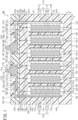
FIG. 1 is a cross-sectional view illustrating a bipolar lead-acid storage battery that is a first embodiment of a bipolar storage battery of the present invention; -
FIG. 2 is a plan view illustrating a positive electrode terminal component and a negative electrode terminal component included in the first to third embodiments of the bipolar storage battery of the present invention; -
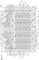
FIG. 3 is a cross-sectional view illustrating a bipolar lead-acid storage battery that is the second embodiment of the bipolar storage battery of the present invention; -
FIG. 4 is a cross-sectional view illustrating a bipolar lead-acid storage battery that is the third embodiment of the bipolar storage battery of the present invention; and -
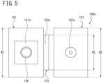
FIG. 5 is a plan view illustrating a terminal component usable as the positive electrode terminal component and the negative electrode terminal component. - Hereinafter, embodiments of the present invention will be described, but the present invention is not limited to the embodiments described below. In the embodiments described below, technically preferable limitations are made to implement the present invention, but these limitations are not essential requirements of the present invention.
- As illustrated in
FIG. 1 , a bipolar lead-acid storage battery 100 of the first embodiment includes a plurality ofcell members 110, a plurality of biplates (space forming members) 120, a first end plate (space forming member) 130, a second end plate (space forming member) 140, alid 150, a positiveelectrode terminal component 160, and a negativeelectrode terminal component 170.FIG. 1 illustrates the bipolar lead-acid storage battery 100 in which sixcell members 110 are stacked, but the number ofcell members 110 is determined depending on battery design. In addition, the number of thebiplates 120 is specified according to the number ofcell members 110. - Here, a stacking direction of the
cell members 110 is defined as an X direction (the left-right direction inFIG. 1 ), and a direction that is perpendicular to the X direction and is an up-down direction in an installed state is defined as a Z direction (the up-down direction inFIG. 1 ). - The
lid 150 covers an upper end surface of the battery main body formed in a substantially rectangular parallelepiped shape and includesrecesses electrode terminal component 160 is arranged in therecess 151, and the negativeelectrode terminal component 170 is arranged in therecess 152. Through-holes bottom plates recesses hole 151b is formed at a position in an upper part of thefirst end plate 130, and the through-hole 152b is formed at a position in an upper part of thesecond end plate 140. - The
cell member 110 includes apositive electrode 111, anegative electrode 112, and a separator (electrolyte layer) 113. Theseparator 113 is impregnated with an electrolytic solution. Thepositive electrode 111 includes a positive electrode lead foil (positive electrode current collector plate) 111a or 111aa and a positiveactive material layer 111b. Thenegative electrode 112 includes a negative electrode lead foil (negative electrode current collector plate) 112a or 112aa and a negativeactive material layer 112b. Theseparator 113 is interposed between thepositive electrode 111 and thenegative electrode 112. In thecell member 110, the positiveelectrode lead foil 111a or 111aa, the positiveactive material layer 111b, theseparator 113, the negativeactive material layer 112b, and the negativeelectrode lead foil 112a or 112aa are stacked in this order. - A dimension (thickness) in the X direction is larger (thicker) in the positive
electrode lead foil 111a than in the negativeelectrode lead foil 112a and is larger (thicker) in the positiveactive material layer 111b than in the negativeactive material layer 112b. - The plurality of
cell members 110 is arranged in a stacked manner with intervals in the X direction, and a substrate 121 of thebiplate 120 is arranged in this interval portion. That is, the plurality ofcell members 110 are stacked with the substrate 121 of thebiplate 120 sandwiched between thecell members 110. In addition, the positive electrode lead foil 111aa constitutes thecell member 110 arranged at one end in the stacking direction, and the negative electrode lead foil 112aa constitutes thecell member 110 arranged at the other end in the stacking direction. - The plurality of
biplates 120, thefirst end plate 130, and thesecond end plate 140 are members for forming a plurality of spaces (cells) C for individually accommodating the plurality ofcell members 110. - The
biplate 120 includes the substrate 121 having a rectangular planar shape, aframe body 122 arranged outside four end surfaces of the substrate 121 and surrounding four side surfaces of thecell member 110, and one or a plurality of column portions (not illustrated) vertically protruding from two surfaces of the substrate 121, and the substrate 121, theframe body 122, and the column portions are integrally formed of a synthetic resin such as acrylonitrile-butadiene-styrene copolymer (ABS). - In the X direction, a dimension of the
frame body 122 is larger than a dimension (thickness) of the substrate 121, and a dimension between protruding end surfaces of the column portion is the same as the dimension of theframe body 122. Then, the space C is formed between the substrate 121 and the substrate 121 by arranging the plurality ofbiplates 120 in a stacked manner with theframe bodies 122 and the column portions in contact with each other, and a dimension of the space C in the X direction is maintained by the column portions that are in contact with each other. - A through-hole (not illustrated) for the column portion to penetrate through is formed in each of the positive
electrode lead foil 111a or 111aa, the positiveactive material layer 111b, the negativeelectrode lead foil 112a or 112aa, the negativeactive material layer 112b, and theseparator 113. - The substrate 121 of the
biplate 120 has a plurality of through-holes 121a penetrating a plate surface. A first recess 121b is formed on one surface of the substrate 121, and a second recess 121c is formed on the other surface of the substrate 121. A depth of the first recess 121b is deeper than a depth of the second recess 121c. Dimensions of the first recess 121b and the second recess 121c in the X direction and a Y direction is made correspondent to the dimensions of the positiveelectrode lead foil 111a and the negativeelectrode lead foil 112a in the X direction and the Y direction. - The substrate 121 of the
biplate 120 is arranged between thecell members 110 neighboring to each other in the X direction. The substrate 121 of thebiplate 120 is a substrate that covers both a side of thepositive electrode 111 of onecell member 110 and a side of thenegative electrode 112 of anothercell member 110 next to the onecell member 110. The positiveelectrode lead foil 111a of thecell member 110 is arranged in the first recess 121b of the substrate 121 of thebiplate 120 via anadhesive layer 114. - In addition, the negative
electrode lead foil 112a of thecell member 110 is arranged in the second recess 121c of the substrate 121 of thebiplate 120 via theadhesive layer 114. - An
electrical conductor 115 is arranged in the through-hole 121a of the substrate 121 of thebiplate 120, and two end surfaces of theelectrical conductor 115 are in contact with and coupled to the positiveelectrode lead foil 111a and the negativeelectrode lead foil 112a. That is, the positiveelectrode lead foil 111a and the negativeelectrode lead foil 112a are electrically connected by theelectrical conductor 115. As a result, all of the plurality ofcell members 110 are electrically connected in series. - In addition, the
frame body 122 of the substrate 121 has surrounding portions surrounding the respective four side surfaces of thecell member 110, and in a surroundingportion 122a surrounding a side surface (one of the side surfaces) on an upper side in the Z direction among the surrounding portions, agroove 128 stretching from an outer side surface to an inner side surface of the surroundingportion 122a is formed in one end surface in the X direction at a position different from the position of the cross section illustrated inFIG. 1 , as indicated by the broken line inFIG. 1 . - The
first end plate 130 includes asubstrate 131 covering a side of the positive electrode of thecell member 110, aframe body 132 surrounding the four side surfaces of thecell member 110, and one or a plurality of column portions (not illustrated) vertically protruding from one surface of the substrate 131 (a surface facing the substrate 121 of thebiplate 120 arranged closest to the side of the positive electrode). A planar shape of thesubstrate 131 is rectangular, theframe body 132 is arranged outside four end surfaces of thesubstrate 131, and thesubstrate 131, theframe body 132, and the column portions are integrally formed of a synthetic resin such as ABS. - In the X direction, a dimension of the
frame body 132 is larger than a dimension (thickness) of thesubstrate 131, and a dimension between protruding end surfaces of the column portion is the same as the dimension of theframe body 132. Then, the space C is formed between the substrate 121 of thebiplate 120 and thesubstrate 131 of thefirst end plate 130 by arranging theframe body 132 and the column portions in a stacked manner in contact with theframe body 122 and the column portions of thebiplate 120 arranged on an outermost side (positive electrode side), and a dimension of the space C in the X direction is maintained by the column portion of thebiplate 120 and the column portion of thefirst end plate 130 in contact with each other. - A through-hole (not illustrated) for the column portion to penetrate through is formed in each of the positive electrode lead foil 111aa, the positive
active material layer 111b, and theseparator 113 of thecell member 110 arranged at one end in the stacking direction. - A
recess 131b is formed on one surface of thesubstrate 131 of thefirst end plate 130. A dimension of therecess 131b in the X direction is made correspondent to a dimension of the positive electrode lead foil 111aa in the X direction. The dimension of the positive electrode lead foil 111aa arranged on one surface of thesubstrate 131 of thefirst end plate 130 in the X direction is larger than a dimension of the positiveelectrode lead foil 111a arranged on one surface of the substrate 121 of thebiplate 120 in the X direction. The positive electrode lead foil 111aa includes a positiveelectrode lug portion 11. - The
frame body 132 has surrounding portions surrounding the respective four side surfaces of thecell member 110, and a through-hole 133 extending in the Z direction is formed in a surrounding portion (a portion covered with the lid) 132a surrounding a side surface (one of the side surfaces) on an upper side in the Z direction, among the surrounding portions. In addition, as indicated by the broken line inFIG. 1 , agroove 138 stretching from an outer side surface to an inner side surface of the surroundingportion 132a is formed in one end surface of the surroundingportion 132a in the X direction at a position different from the position of the cross section illustrated inFIG. 1 . Furthermore, a lugportion arrangement recess 131c that is continuous with the through-hole 133 and stretches to therecess 131b is formed on one surface of thesubstrate 131. As indicated by the broken line inFIG. 1 , thegroove 128 stretching from the outer side surface to the inner side surface of the surroundingportion 122a is formed. - A portion of the positive electrode lead foil 111aa other than the positive
electrode lug portion 11 is arranged in therecess 131b of thesubstrate 131 via theadhesive layer 114, a base portion of the positiveelectrode lug portion 11 is arranged in the lugportion arrangement recess 131c of thesubstrate 131, and an intermediate portion of the positiveelectrode lug portion 11 penetrates through the through-hole 133 of theframe body 132 of thefirst end plate 130 and the through-hole 151b of thebottom plate 151a of thelid 150. Then, a tip portion of the positiveelectrode lug portion 11 is bent at a substantially right angle inside therecess 151 of thelid 150. - That is, the positive
electrode lug portion 11 includes abent portion 11a at a point ahead of a location where the positiveelectrode lug portion 11 penetrates the surroundingportion 132a of theframe body 132 constituting thefirst end plate 130 and thebottom plate 151a of therecess 151 of thelid 150. Then, thebent portion 11a of the positiveelectrode lug portion 11 is connected with the positiveelectrode terminal component 160. In addition, a gap between the positiveelectrode lug portion 11, and the through-hole 133 of theframe body 132 and the through-hole 151b of thelid 150 is sealed with asynthetic resin 135 made of an epoxy resin. Furthermore, the inside of therecess 151 of thelid 150 is sealed with asynthetic resin 155 made of an epoxy resin. - The
second end plate 140 includes asubstrate 141 covering a side of the negative electrode of thecell member 110, aframe body 142 surrounding the four side surfaces of thecell member 110, and one or a plurality of column portions (not illustrated) vertically protruding from one surface of the substrate 141 (a surface facing the substrate 121 of thebiplate 120 arranged closest to the side of the negative electrode). A planar shape of thesubstrate 141 is rectangular, theframe body 142 is arranged outside four end surfaces of thesubstrate 141, and thesubstrate 141, theframe body 142, and the column portions are integrally formed of a synthetic resin such as ABS. - In the X direction, a dimension of the
frame body 142 is larger than a dimension (thickness) of thesubstrate 141, and a dimension between two protruding end surfaces of acolumn portion 143 is the same as the dimension of theframe body 142. Then, the space C is formed between the substrate 121 of thebiplate 120 and thesubstrate 141 of thesecond end plate 140 by arranging theframe body 142 and the column portions in a stacked manner in contact with theframe body 122 and the column portions of thebiplate 120 arranged on an outermost side (negative electrode side), and a dimension of the space C in the X direction is maintained by the column portion of thebiplate 120 and the column portion of thesecond end plate 140 in contact with each other. - A through-hole (not illustrated) for the
column portion 143 to penetrate through is formed in each of the negative electrode lead foil 112aa, the negativeactive material layer 112b, and theseparator 113 of thecell member 110 arranged at the other end in the stacking direction. - A
recess 141b is formed on one surface of thesubstrate 141 of thesecond end plate 140. A dimension of therecess 141b in the X direction is made correspondent to a dimension of the negative electrode lead foil 112aa in the X direction. The dimension of the negative electrode lead foil 112aa arranged on one surface of thesubstrate 141 of thesecond end plate 140 in the X direction is larger than a dimension of the negativeelectrode lead foil 112a arranged on the other surface of the substrate 121 of thebiplate 120 in the X direction. The negative electrode lead foil 112aa includes a negativeelectrode lug portion 12. - The
frame body 142 has surrounding portions surrounding the respective four side surfaces of thecell member 110, and a through-hole 143 extending in the Z direction is formed in a surroundingportion 142a surrounding a side surface (one of the side surfaces) on an upper side in the Z direction, among the surrounding portions. In addition, as indicated by the broken line inFIG. 1 , agroove 148 stretching from an outer side surface to an inner side surface of the surroundingportion 142a is formed in one end surface of the surroundingportion 142a in the X direction at a position different from the position of the cross section illustrated inFIG. 1 . Furthermore, a lugportion arrangement recess 141c that is continuous with the through-hole 143 and stretches to therecess 141b is formed on one surface of thesubstrate 141. - A portion of the negative electrode lead foil 112aa other than the negative
electrode lug portion 12 is arranged in therecess 141b of thesubstrate 141 via theadhesive layer 114, a base portion of the negativeelectrode lug portion 12 is arranged in the lugportion arrangement recess 141c of thesubstrate 141, and an intermediate portion of the negativeelectrode lug portion 12 penetrates through the through-hole 143 of theframe body 142 of thesecond end plate 140 and the through-hole 152b of thebottom plate 152a of thelid 150. Then, a tip portion of the negativeelectrode lug portion 12 is bent at a substantially right angle inside therecess 152 of thelid 150. - That is, the negative
electrode lug portion 12 includes abent portion 12a at a point ahead of a location where the negativeelectrode lug portion 12 penetrates the surroundingportion 142a of theframe body 142 constituting thesecond end plate 140 and thebottom plate 152a of therecess 152 of thelid 150. Then, thebent portion 12a of the negativeelectrode lug portion 12 is connected with the negativeelectrode terminal component 170. In addition, a gap between the negativeelectrode lug portion 12, and the through-hole 143 of theframe body 142 and the through-hole 152b of thelid 150 is sealed with asynthetic resin 145 made of an epoxy resin. Furthermore, the inside of therecess 152 of thelid 150 is sealed with thesynthetic resin 155 made of an epoxy resin. - The positive electrode lead foils (positive electrode current collector plates) 111a and 111aa are formed of, for example, a lead alloy in which a content of tin (Sn) is 1.0% by mass or more but less than 2.0% by mass, a content of calcium (Ca) is 0.005% by mass or more but less than 0.030% by mass, and the rest is lead (Pb) and unavoidable impurities.
- The negative electrode lead foils (negative electrode current collector plates) 121a and 112aa are formed of, for example, a lead alloy in which a content of tin (Sn) is 0.5% by mass or more but equal to or less than 2% by mass.
- Note that, as can be seen from the above description, the
biplate 120 is a space forming member including the substrate 121 covering both a side of the positive electrode and a side of the negative electrode of thecell member 110 and theframe body 122 surrounding all side surfaces of thecell member 110. Thefirst end plate 130 is a space forming member including thesubstrate 131 covering only a side of the positive electrode (one of a side of the positive electrode and a side of the negative electrode) of thecell member 110 and theframe body 132 surrounding all side surfaces of thecell member 110. - The
second end plate 140 is a space forming member including thesubstrate 141 covering only a side of the negative electrode (one of a side of the positive electrode and a side of the negative electrode) of thecell member 110 and theframe body 142 surrounding all side surfaces of thecell member 110. That is, each of thesubstrates cell member 110, and the substrate 121 is a substrate covering both the side of the positive electrode and the side of the negative electrode of thecell member 110. - In addition, at a position different from the position of the cross section illustrated in
FIG. 1 , liquid injection holes 18 each stretching from the outer side surface to the inner side surface of the surroundingportions grooves 128 included in the surroundingportions 122a of theadjacent biplates 120, and thegrooves portions first end plate 130 and thesecond end plate 140 and thegrooves 128 that are adjacent to thegrooves portions 122a of thebiplates 120. Eachliquid injection hole 18 is continuous with each liquid inlet provided in thelid 150. An electrolytic solution is present in each space C, and theseparator 113 is in an impregnated state with the electrolytic solution. - As illustrated in
FIGS. 1 and2 , the positiveelectrode terminal component 160 includes aterminal portion 161 including aconnection surface 161a with an external terminal and a linkingportion 162 with which thebent portion 11a of the positiveelectrode lug portion 11 is connected, in different regions in a plan view. Anintermediate portion 163 is provided between theterminal portion 161 and the linkingportion 162. A V-shapedgroove 163a is formed on an upper surface of theintermediate portion 163. That is, the positiveelectrode terminal component 160 includes, between theterminal portion 161 and the linkingportion 162, theintermediate portion 163 having a surface lower than an upper surface of the linking portion 162 (a surface on an opposite side of the surroundingportion 132a). - A width W2 of the linking
portion 162 in a plan view is the same as or larger than a width of thebent portion 11a of the positiveelectrode lug portion 11. A width W1 of theterminal portion 161 in a plan view and a width W3 of theintermediate portion 163 in a plan view are the same, and the width W2 of the linkingportion 162 in a plan view is larger than the width W1 of theterminal portion 161 in a plan view. That is, a portion between theterminal portion 161 and the linkingportion 162 is formed to have a width narrower than the width of the linkingportion 162 in a plan view. -
FIG. 1 illustrates a cross section at a center position in a direction perpendicular to the X direction and the Z direction. As can be seen fromFIG. 1 , theterminal portion 161 includes aprotrusion portion 164 extending in a thickness direction of thelid 150. Theconnection surface 161a is formed at a tip of theprotrusion portion 164, and a narrowedportion 165 is formed at a base portion of theprotrusion portion 164. That is, an upper surface of theprotrusion portion 164 serves as theconnection surface 161a, and a vertically standingscrew shaft 166 is formed at a center of theconnection surface 161a. - As illustrated in
FIG. 2 , a truncated cone-shapedprojection 162a standing vertically is formed on an outer surface of the linkingportion 162 before assembly. Note that a through-hole through which the truncated cone-shapedprojection 162a passes is provided at a tip portion of the positiveelectrode lug portion 11 before assembly. - The positive
electrode terminal component 160 other than thescrew shaft 166 is, for example, a cast product made of lead or a lead alloy, and thescrew shaft 166 made of brass is integrated (insert-molded) at the time of casting. - The negative
electrode terminal component 170 is the same as the positiveelectrode terminal component 160 and has aterminal portion 171 including aconnection surface 171a, a linkingportion 172, and anintermediate portion 173, and a V-shapedgroove 173a is formed on an upper surface of theintermediate portion 173. Theterminal portion 171 includes aprotrusion portion 174 protruding from a plane including an outer surface of the linking portion 172 (a surface on an opposite side of the battery main body), and theprotrusion portion 174 includes a narrowedportion 175. An upper surface of theprotrusion portion 174 serves as theconnection surface 171a, and ascrew shaft 176 protrudes from a center of theconnection surface 171a. - When the bipolar lead-
acid storage battery 100 is used, for example, respective round terminals connected to a positive electrode wiring line and a negative electrode wiring line are fitted to thescrew shafts electrode terminal component 160 and the negativeelectrode terminal component 170, and nuts are screwed and fastened to thescrew shafts acid storage battery 100 is connected with the positive electrode wiring line and the negative electrode wiring line. - When the bipolar lead-
acid storage battery 100 is manufactured, first, the battery main body is assembled in a state in which tips of the positiveelectrode lug portion 11 and the negativeelectrode lug portion 12 extend upward in the Z direction. - The battery main body is assembled by, for example, the following method.
- First, the positive
electrode lead foil 111a is fixed to the first recess 121b and the negativeelectrode lead foil 112a is fixed to the second recess 121c of thebiplate 120 with an adhesive, and the positiveelectrode lead foil 111a and the negativeelectrode lead foil 112a are connected by theelectrical conductor 115 by a resistance welding method. - Next, in a state in which the tip portion of the positive
electrode lug portion 11 of the positive electrode lead foil 111aa appears outside after passing through the through-hole 133 of theframe body 132 of thefirst end plate 130, the base portion of the positiveelectrode lug portion 11 is fixed to the lugportion arrangement recess 131c of thesubstrate 131, and the portion other than the positiveelectrode lug portion 11 is fixed to therecess 131b of thesubstrate 131, each with an adhesive. - In addition, in a state in which the tip portion of the negative
electrode lug portion 12 of the negative electrode lead foil 112aa appears outside after passing through the through-hole 143 of theframe body 142 of thesecond end plate 140, the base portion of the negativeelectrode lug portion 12 is fixed to the lugportion arrangement recess 141c of thesubstrate 141, and the portion other than the negativeelectrode lug portion 12 is fixed to therecess 141b of thesubstrate 141, each with an adhesive. - In this manner, each plate to which each lead foil is fixed is obtained.
- Next, repeatedly in the order of the
first end plate 130 and all thebiplates 120, the positive active material layer, the separator, and the negative active material layer are placed on the positive electrode lead foil fixed to each plate, and the plates are stacked and joined to each other by a vibration welding method. Finally, the negative electrode lead foil of thesecond end plate 140 is placed on the negative active material layer of thebiplate 120, and thesecond end plate 140 is joined to thebiplate 120 by a vibration welding method. Specifically, the facing surfaces of the frame bodies and the column portions of the substrates serve as joining surfaces to form each of the spaces (cells) C, and a state in which onecell member 110 is arranged in one cell C is achieved. In addition, the liquid injection holes 18 are formed by vibration welding on edge portions of thegrooves - Next, the
lid 150 is arranged in an upper part of the battery main body in the Z direction, and thelid 150 is put on an upper surface of the battery main body in the Z direction and thermally welded while tips of the positiveelectrode lug portion 11 and the negativeelectrode lug portion 12 are passed through the through-holes lid 150. Next, a sealing agent is injected from the through-holes hole 133 to seal between the through-holes electrode lug portion 11 and the negativeelectrode lug portion 12 and between the intermediate portion of the positiveelectrode lug portion 11 and the through-hole 133 of theframe body 132 with thesynthetic resin 135. - Next, the positive
electrode terminal component 160 and the negativeelectrode terminal component 170 are installed in therecesses lid 150, respectively, and are fixed to upper surfaces of thebottom plates electrode lug portion 11 and the negativeelectrode lug portion 12 are bent at predetermined positions and arranged on top of the linkingportions electrode terminal component 160 and the negativeelectrode terminal component 170, respectively. At this time, the truncated cone-shapedprojections electrode lug portion 11 and the negativeelectrode lug portion 12. Next, the truncated cone-shapedprojections electrode lug portion 11 and the negativeelectrode lug portion 12 are connected with the linkingportions - Next, an electrolytic solution is injected to the inside of each cell C from each liquid inlet of the
lid 150 via eachliquid injection hole 18 of the battery main body, and then each liquid inlet of thelid 150 is closed. - As described above, in the bipolar lead-
acid storage battery 100 of the first embodiment, the tips of the positiveelectrode lug portion 11 and the negativeelectrode lug portion 12 are connected with the linkingportion electrode terminal component 160 and the negativeelectrode terminal component 170 at points ahead of locations where the tips of the positiveelectrode lug portion 11 and the negativeelectrode lug portion 12 penetrate the surroundingportions first end plate 130 and thesecond end plate 140 and thebottom plates lid 150. That is, in the bipolar lead-acid storage battery 100 of the first embodiment, the current collector plate and the terminal are connected at a position different from a position where there is a high risk of coming into contact with the electrolytic solution that has been raised along the current collector plate due to the capillary phenomenon, such as a space between the battery main body and the lid (electrode receiving space of PTL 1), (a position away from the position where there is a high risk). - As a consequence of this, in the bipolar lead-
acid storage battery 100 of the first embodiment, the connection portions (the linkingportions electrode terminal component 160 and the negative electrode terminal component 170) of the terminals with the lug portions of the current collectors (thebent portions electrode lug portion 11 and the negative electrode lug portion 12) are difficult to corrode because of the electrolytic solution raised along the current collector plate due to the capillary phenomenon. - In addition, since the through-holes (the through-
holes portions holes electrode lug portion 11 and the negativeelectrode lug portion 12 to pass through are sealed with thesynthetic resins lid 150 is achieved. - In addition, since the
lid 150 includes therecesses electrode lug portion 11 and the negativeelectrode lug portion 12 include thebent portions bent portions electrode lug portion 11 and the negativeelectrode lug portion 12 and the linkingportions electrode terminal component 160 and the negativeelectrode terminal component 170 are connected inside therecesses lid 150, the thickness (the dimension in the Z direction) of thelid 150 can be reduced while the lengths of the positiveelectrode lug portion 11 and the negativeelectrode lug portion 12 are increased. - Furthermore, since the
bent portions electrode lug portion 11 and the negativeelectrode lug portion 12 and the linkingportions electrode terminal component 160 and the negativeelectrode terminal component 170 are arranged inside therecesses lid 150, and the inside of therecesses synthetic resin 155, the linkingportions 162 and 172 (connection portions with thebent portions - In addition, since the positive
electrode terminal component 160 and the negativeelectrode terminal component 170 include theintermediate portions terminal portions portions bent portions electrode lug portion 11 and the negativeelectrode lug portion 12 to arrive at theterminal portions - In addition, since the width W2 of the linking
portions electrode terminal component 160 and the negativeelectrode terminal component 170 in a plan view is the same as or larger than the widths of thebent portions electrode lug portion 11 and the negativeelectrode lug portion 12, a structure that makes it difficult for the electrolytic solution that has reached thebent portions electrode lug portion 11 and the negativeelectrode lug portion 12 to arrive at theterminal portions - In addition, since the
terminal portions electrode terminal component 160 and the negativeelectrode terminal component 170 include theprotrusion portions portions protrusion portions portions terminal portions portions - In addition, since the width W3 of the
intermediate portions electrode terminal component 160 and the negativeelectrode terminal component 170 in a plan view is formed narrower than the width W2 of the linkingportions bent portions electrode lug portion 11 and the negativeelectrode lug portion 12 to arrive at theterminal portions - From the above, the bipolar lead-
acid storage battery 100 of the first embodiment has a structure that not only makes it difficult for the linkingportions 162 and 172 (the connection portions with thebent portions electrode lug portion 11 and negative electrode lug portion 12) of the positiveelectrode terminal component 160 and the negativeelectrode terminal component 170 to corrode, but also makes it difficult for theterminal portions electrode terminal component 160 and the negativeelectrode terminal component 170 to corrode is achieved. - As illustrated in
FIG. 3 , a bipolar lead-acid storage battery 100A of a second embodiment is the same as the bipolar lead-acid storage battery 100 of the first embodiment except for a part thereof, and thus different points will be described below. - A
lid 150A constituting the bipolar lead-acid storage battery 100A of the second embodiment includes a plurality ofprojections 156 at positions on upper surfaces ofbottom plates recesses electrode terminal component 160 and a negativeelectrode terminal component 170 are arranged. A dimension in the Z direction of thelid 150A is larger than the dimension in the Z direction of thelid 150 of the first embodiment by an amount equal to the height of theprojection 156. - Then, the positive
electrode terminal component 160 and the negativeelectrode terminal component 170 are arranged on top of the plurality ofprojections 156. The plurality ofprojections 156 are members forming a space between the positiveelectrode terminal component 160 and the negativeelectrode terminal component 170, and thebottom plates synthetic resin 155 is present in this space. Note that, when the positiveelectrode terminal component 160 and the negativeelectrode terminal component 170 are fixed to the inside of therecesses lid 150A with an adhesive at the time of manufacturing, the adhesive runs around into this space. - The bipolar lead-
acid storage battery 100A of the second embodiment has the following effects in addition to the actions and effects that the bipolar lead-acid storage battery 100 of the first embodiment has. - In the bipolar lead-
acid storage battery 100A of the second embodiment, since the positiveelectrode terminal component 160 and the negativeelectrode terminal component 170 are installed on top of the plurality ofprojections 156 provided on thebottom plates recesses lid 150A, as compared with the bipolar lead-acid storage battery 100 of the first embodiment in which the positiveelectrode terminal component 160 and the negativeelectrode terminal component 170 are installed directly on the upper surfaces of thebottom plates electrode terminal component 160 and the negativeelectrode terminal component 170 along the upper surfaces of thebottom plates - In addition, since lower portions of the positive
electrode terminal component 160 and the negativeelectrode terminal component 170 are in a bonded state to thebottom plates synthetic resin 155 present between the plurality ofprojections 156, the positiveelectrode terminal component 160 and the negativeelectrode terminal component 170 are more firmly fixed to the lid than in the bipolar lead-acid storage battery 100 of the first embodiment. Therefore, when external terminals are fastened to the positiveelectrode terminal component 160 and the negativeelectrode terminal component 170 by screwingscrew shafts electrode terminal component 160 and the negativeelectrode terminal component 170 can withstand a larger fastening stress and torque. - As illustrated in
FIG. 4 , a bipolar lead-acid storage battery 100B of a third embodiment is the same as the bipolar lead-acid storage battery 100A of the second embodiment except for a part thereof, and thus different points will be described below. - A
lid 150B constituting the bipolar lead-acid storage battery 100B of the third embodiment includesribs 158 at positions on upper surfaces ofbottom plates recesses bent portions electrode lug portion 11 and a negative electrode lug portion 12 (portions behind connection portions with a positiveelectrode terminal component 160 and a negative electrode terminal component 170) are arranged. Theribs 158 support thebent portions acid storage battery 100B of the third embodiment includes pressingmembers 180 configured to press thebent portions ribs 158. - The bipolar lead-
acid storage battery 100B of the third embodiment has the following effects in addition to the actions and effects that the bipolar lead-acid storage battery 100A of the second embodiment has. - Since the
ribs 158 supporting base portions of thebent portions bent portions bent portions electrode terminal component 160 and the negative electrode terminal component 170), as compared with the bipolar lead-acid storage battery 100 of the first embodiment without such ribs. - In addition, since the
bent portions ribs 158 and also pushed from an upper side with thepressing members 180, bent states of thebent portions electrode lug portion 11 and the negativeelectrode lug portion 11 when pressure is applied from the outside is restrained. In addition, since thepressing members 180 are present on the upper side of thebent portions synthetic resin 155 when pressure is applied from the outside to thesynthetic resin 155 sealing therecesses - Note that the
lids lid 150B made of ABS is joined to the battery main body to seal between the positiveelectrode lug portion 11 and the negativeelectrode lug portion 12 and the through-holes recesses synthetic resin 155 after peripheral edge portions of the through-holes bottom plates ribs 158 on sides of the positiveelectrode lug portion 12 and the negativeelectrode lug portion 12, using a sealing agent for melting ABS, before bending tip portions of the positiveelectrode lug portion 11 and the negativeelectrode lug portion 12. - As the positive electrode terminal component and the negative electrode terminal component, as in a
terminal component 160A illustrated inFIG. 5 , a terminal component may be used in which the width W1 of theterminal portion 161 in a plan view and the width W2 of the linkingportion 162 in a plan view are the same, and the width W3 of theintermediate portion 163 in a plan view is smaller than the width W1 of theterminal portion 161 in a plan view. That is, theterminal component 160A is the same as the positiveelectrode terminal component 160 inFIG. 1 except that the dimensional relationship is W1 = W2 > W3. - The
terminal component 160A has a structure that makes it difficult for the electrolytic solution that has arrived at theterminal portions connection surface 161a, as compared with a terminal component having a dimensional relationship of W1 = W3 < W2. Therefore, by using theterminal component 160A as the positiveelectrode terminal component 160 and the negativeelectrode terminal component 170, even when the electrolytic solution has arrived at theterminal portion 161, theconnection surface 161a can be avoided from being corroded. - In addition, as the positive electrode terminal component and the negative electrode terminal component, the positive
electrode terminal component 160 having a recess instead of the V-shapedgroove 163a, or the positiveelectrode terminal component 160 formed with a groove having an inclined surface (a surface lower than an upper surface of the linking portion) lowering or rising from the linkingportion 162 toward the terminal portion 161 (a groove having a right triangular cross section) may be used. - In the bipolar lead-acid storage battery of each of the above embodiments, the
lid 150 having therecesses - In each of the above embodiments, the bipolar lead-acid storage battery in which the positive electrode current collector plate and the negative electrode current collector plate are made of a lead foil (formed of lead or a lead alloy) has been described, but one aspect of the present invention can also be applied to a bipolar storage battery in which the positive electrode current collector plate and the negative electrode current collector plate are formed of a metal (such as aluminum, copper, or nickel) or an alloy other than lead or a lead alloy, or a conductive resin.
- In each of the above embodiments, the respective bent portions of the positive electrode lug portion and the negative electrode lug portion are connected with the positive electrode terminal component and the negative electrode terminal component by thermal welding, but may be connected with the positive electrode terminal component and the negative electrode terminal component by any of welding, caulking, bolt fastening, pressure bonding, and spring fixing. Since these connection forms (thermal welding, welding, caulking, bolt fastening, pressure bonding, spring fixing) are vulnerable to corrosion, the effects obtained by the present invention are higher.
-
- 11 Positive electrode lug portion
- 11a Bent portion of positive electrode lug portion
- 12 Negative electrode lug portion
- 12a Bent portion of negative electrode lug portion
- 100 Bipolar lead-acid storage battery
- 110 Cell member
- 111 Positive electrode
- 112 Negative electrode
- 111a Positive electrode lead foil
- 111aa Positive electrode lead foil (positive electrode current collector plate constituting one cell member)
- 111b Positive active material layer
- 112a Negative electrode lead foil
- 112aa Negative electrode lead foil (negative electrode current collector plate constituting one cell member)
- 112b Negative active material layer
- 113 Separator
- 114 Adhesive layer
- 115 Electrical conductor
- 120 Biplate (space forming member)
- 121 Substrate of biplate (substrate covering both side of positive electrode and side of negative electrode of cell member)
- 121a Through-hole of substrate
- 121b First recess of substrate
- 121c Second recess of substrate
- 122 Frame body of biplate
- 122a Surrounding portion surrounding one of side surfaces of cell member
- 128 Groove forming liquid injection hole
- 130 First end plate (space forming member)
- 131 Substrate of first end plate (substrate covering one of side of positive electrode and side of negative electrode of cell member)
- 132 Frame body of first end plate
- 132a Surrounding portion surrounding one of side surfaces of cell member
- 135 Synthetic resin sealing through-hole
- 138 Groove forming liquid injection hole
- 140 Second end plate (space forming member)
- 141 Substrate of second end plate (substrate covering one of side of positive electrode and side of negative electrode of cell member)
- 142 Frame body of second end plate
- 142a Surrounding portion surrounding one of side surfaces of cell member
- 145 Synthetic resin sealing through-hole
- 148 Groove forming liquid injection hole
- 150 Lid
- 151 Recess of lid
- 152 Recess of lid
- 155 Synthetic resin sealing recess of lid
- 160 Positive electrode terminal component
- 161 Terminal portion of positive electrode terminal component
- 161a Connection surface of positive electrode terminal component
- 162 Linking portion of positive electrode terminal component
- 163 Intermediate portion of positive electrode terminal component
- 164 Protrusion portion of positive electrode terminal component
- 165 Narrowed portion of positive electrode terminal component
- 170 Negative electrode terminal component
- 171 Terminal portion of negative electrode terminal component
- 171a Connection surface of negative electrode terminal component
- 172 Linking portion of negative electrode terminal component
- 173 Intermediate portion of negative electrode terminal component
- 174 Protrusion portion of negative electrode terminal component
- 175 Narrowed portion of negative electrode terminal component
- 18 Liquid injection hole
- C Cell (space accommodating cell member)
Claims (16)
- A bipolar storage battery comprising:a plurality of cell members each including a positive electrode including a positive electrode current collector plate and a positive active material layer, a negative electrode including a negative electrode current collector plate and a negative active material layer, and a separator interposed between the positive electrode and the negative electrode, the plurality of cell members being arranged in a stacked manner with intervals; anda plurality of space forming members configured to form a plurality of spaces for individually accommodating the plurality of cell members,wherein an electrolytic solution is present in the spaces,the space forming members each include a substrate configured to cover at least one of a side of the positive electrode or a side of the negative electrode of one of the cell members and a frame body configured to surround all side surfaces of one of the cell members,the cell members and the substrates of the space forming members are arranged in an alternately stacked state,the plurality of cell members is electrically connected in series,the frame bodies being adjacent are joined,the bipolar storage battery comprises: a lid configured to cover a surrounding portion of the frame body surrounding one of the side surfaces of each cell member; and a positive electrode terminal component and a negative electrode terminal component each including a connection surface exposed to an outer surface of the lid,the positive electrode current collector plate constituting one of the cell members includes a positive electrode lug portion, and the positive electrode lug portion is connected with the positive electrode terminal component at a point ahead of a location where the positive electrode lug portion penetrates the surrounding portion and the lid, andthe negative electrode current collector plate constituting one of the cell members includes a negative electrode lug portion, and the negative electrode lug portion is connected with the negative electrode terminal component at a point ahead of a location where the negative electrode lug portion penetrates the surrounding portion and the lid.
- The bipolar storage battery according to claim 1, comprising a through-hole configured to penetrate the surrounding portion and the lid sequentially, wherein the through-hole is sealed with a synthetic resin.
- The bipolar storage battery according to claim 1 or 2,wherein the lid includes a recess on a surface opposite to a side of the frame body, and the positive electrode terminal component and the negative electrode terminal component are arranged in the recess, andeach of the positive electrode lug portion and the negative electrode lug portion includes a bent portion at a point ahead of a location where the positive electrode lug portion or the negative electrode lug portion penetrates the surrounding portion and a bottom plate of the recess, and the bent portion is connected with one of the positive electrode terminal component and the negative electrode terminal component.
- The bipolar storage battery according to claim 3, wherein the bent portion of each of the positive electrode lug portion and the negative electrode lug portion is connected with one of the positive electrode terminal component and the negative electrode terminal component by any of thermal welding, welding, caulking, bolt fastening, pressure bonding, or spring fixing.
- The bipolar storage battery according to claim 3, wherein the positive electrode terminal component and the negative electrode terminal component are arranged on top of a plurality of projections configured to protrude from the bottom plate of the recess.
- The bipolar storage battery according to claim 3, wherein the bottom plate of the recess includes a rib configured to support the bent portion.
- The bipolar storage battery according to claim 6, comprising a through-hole configured to penetrate the surrounding portion and the bottom plate of the recess sequentially, wherein a gap between the rib and a wall surface on a side of the recess on which the through-hole is formed is sealed with a synthetic resin.
- The bipolar storage battery according to claim 6, comprising a pressing member configured to press the bent portion against a side of the rib.
- The bipolar storage battery according to claim 3, wherein the recess is sealed with a synthetic resin.
- A bipolar storage battery comprising:a plurality of cell members each including a positive electrode including a positive electrode current collector plate and a positive active material layer, a negative electrode including a negative electrode current collector plate and a negative active material layer, and a separator interposed between the positive electrode and the negative electrode, the plurality of cell members being arranged in a stacked manner with intervals; anda plurality of space forming members configured to form a plurality of spaces for individually accommodating the plurality of cell members,wherein an electrolytic solution is present in the spaces,the space forming members each include a substrate configured to cover at least one of a side of the positive electrode or a side of the negative electrode of one of the cell members and a frame body configured to surround all side surfaces of one of the cell members,the cell members and the substrates of the space forming members are arranged in an alternately stacked state,the plurality of cell members is electrically connected in series,the frame bodies being adjacent are joined,the bipolar storage battery comprises: a lid configured to cover a surrounding portion of the frame body surrounding one of the side surfaces of each cell member; and a positive electrode terminal component and a negative electrode terminal component each including a connection surface exposed to an outer surface of the lid,the positive electrode current collector plate constituting one of the cell members includes a positive electrode lug portion, and the negative electrode current collector plate constituting one of the cell members includes a negative electrode lug portion,each of the positive electrode lug portion and the negative electrode lug portion includes a bent portion at a point ahead of a location where the positive electrode lug portion or the negative electrode lug portion penetrates the surrounding portion and the lid,each of the positive electrode terminal component and the negative electrode terminal component includes a terminal portion including the connection surface and a linking portion configured to connect with the bent portion, in different regions in a plan view,the bent portion of the positive electrode lug portion is connected with the linking portion of the positive electrode terminal component, andthe bent portion of the negative electrode lug portion is connected with the linking portion of the negative electrode terminal component.
- The bipolar storage battery according to claim 10, comprising an intermediate portion including a surface lower than a surface of the linking portion on an opposite side of the surrounding portion, between the terminal portion and the linking portion.
- The bipolar storage battery according to claim 10, wherein the linking portion has a width same as or larger than the width of the bent portion in a plan view.
- The bipolar storage battery according to claim 10, wherein the terminal portions of the positive electrode terminal component and the negative electrode terminal component include a protrusion portion extending in a thickness direction of the lid, the connection surface is formed at a tip of the protrusion portion, and a narrowed portion is formed at a base portion of the protrusion portion.
- The bipolar storage battery according to claim 11, wherein the intermediate portion has a width formed narrower than the width of the linking portion in a plan view.
- The bipolar storage battery according to claim 11, wherein the intermediate portion has a width formed narrower than the width of the linking portion and the terminal portion in a plan view.
- The bipolar storage battery according to any one of claims 10 to 15,wherein the lid includes a recess on a surface opposite to a side of the frame body, and the positive electrode terminal component and the negative electrode terminal component are arranged in the recess, andeach of the positive electrode lug portion and the negative electrode lug portion includes a bent portion at a point ahead of a location where the positive electrode lug portion or the negative electrode lug portion penetrates the surrounding portion and a bottom plate of the recess, and the bent portion is connected with the linking portion of one of the positive electrode terminal component and the negative electrode terminal component.
Applications Claiming Priority (3)
| Application Number | Priority Date | Filing Date | Title |
|---|---|---|---|
| JP2021161020 | 2021-09-30 | ||
| JP2021161021 | 2021-09-30 | ||
| PCT/JP2022/036287 WO2023054524A1 (en) | 2021-09-30 | 2022-09-28 | Bipolar storage battery |
Publications (1)
| Publication Number | Publication Date |
|---|---|
| EP4411970A1 true EP4411970A1 (en) | 2024-08-07 |
Family
ID=85780757
Family Applications (1)
| Application Number | Title | Priority Date | Filing Date |
|---|---|---|---|
| EP22876390.0A Withdrawn EP4411970A1 (en) | 2021-09-30 | 2022-09-28 | Bipolar storage battery |
Country Status (4)
| Country | Link |
|---|---|
| US (1) | US20240234980A1 (en) |
| EP (1) | EP4411970A1 (en) |
| JP (1) | JPWO2023054524A1 (en) |
| WO (1) | WO2023054524A1 (en) |
Family Cites Families (3)
| Publication number | Priority date | Publication date | Assignee | Title |
|---|---|---|---|---|
| JPH06215739A (en) * | 1992-09-09 | 1994-08-05 | Furukawa Battery Co Ltd:The | Storage battery manufacturing method |
| JP2006210210A (en) * | 2005-01-31 | 2006-08-10 | Matsushita Electric Ind Co Ltd | Lead acid battery |
| US9634319B2 (en) * | 2011-09-09 | 2017-04-25 | East Penn Manufacturing Co., Inc. | Bipolar battery and plate |
-
2022
- 2022-09-28 EP EP22876390.0A patent/EP4411970A1/en not_active Withdrawn
- 2022-09-28 WO PCT/JP2022/036287 patent/WO2023054524A1/en not_active Ceased
- 2022-09-28 JP JP2023551807A patent/JPWO2023054524A1/ja active Pending
-
2024
- 2024-03-22 US US18/613,685 patent/US20240234980A1/en active Pending
Also Published As
| Publication number | Publication date |
|---|---|
| WO2023054524A1 (en) | 2023-04-06 |
| JPWO2023054524A1 (en) | 2023-04-06 |
| US20240234980A1 (en) | 2024-07-11 |
Similar Documents
| Publication | Publication Date | Title |
|---|---|---|
| US7507124B2 (en) | Secondary battery module | |
| JP5606851B2 (en) | Battery and battery module | |
| EP2346110B1 (en) | Recharcheable battery | |
| US9017842B2 (en) | Secondary battery pack providing excellent productivity and structural stability | |
| EP2215673B1 (en) | Secondary battery pack of compact structure | |
| KR100879297B1 (en) | Secondary battery | |
| KR101895904B1 (en) | Rechargeable battery and a method of manufacturing the same | |
| KR20100068080A (en) | Rechargeable battery | |
| US9543561B2 (en) | Battery | |
| CN220553565U (en) | Battery cell and battery device | |
| EP3512007B1 (en) | Electrode component, electrode assembly and rechargeable battery | |
| JP2009105075A (en) | Battery | |
| JP5083244B2 (en) | battery | |
| JP2025539144A (en) | Electrochemical devices and electrical devices | |
| US20240234980A1 (en) | Bipolar Storage Battery | |
| US20110287290A1 (en) | Rechargeable battery | |
| CN117941159A (en) | Bipolar accumulator | |
| JP7724279B2 (en) | Bipolar battery | |
| CN115117571A (en) | Battery pack | |
| JP2022161267A (en) | Bipolar storage battery and method for manufacturing bipolar storage battery | |
| JP7265309B2 (en) | bipolar lead acid battery | |
| JP2764135B2 (en) | Electrode group for connection between cells of lead-acid battery | |
| JP5545400B2 (en) | battery | |
| JP2025086043A (en) | Secondary battery and method for manufacturing the same | |
| JP2025150816A (en) | Bipolar storage battery and method for manufacturing the same |
Legal Events
| Date | Code | Title | Description |
|---|---|---|---|
| STAA | Information on the status of an ep patent application or granted ep patent |
Free format text: STATUS: THE INTERNATIONAL PUBLICATION HAS BEEN MADE |
|
| PUAI | Public reference made under article 153(3) epc to a published international application that has entered the european phase |
Free format text: ORIGINAL CODE: 0009012 |
|
| STAA | Information on the status of an ep patent application or granted ep patent |
Free format text: STATUS: REQUEST FOR EXAMINATION WAS MADE |
|
| 17P | Request for examination filed |
Effective date: 20240325 |
|
| AK | Designated contracting states |
Kind code of ref document: A1 Designated state(s): AL AT BE BG CH CY CZ DE DK EE ES FI FR GB GR HR HU IE IS IT LI LT LU LV MC MK MT NL NO PL PT RO RS SE SI SK SM TR |
|
| DAV | Request for validation of the european patent (deleted) | ||
| DAX | Request for extension of the european patent (deleted) | ||
| STAA | Information on the status of an ep patent application or granted ep patent |
Free format text: STATUS: THE APPLICATION HAS BEEN WITHDRAWN |
|
| 18W | Application withdrawn |
Effective date: 20250710 |