EP4411683A1 - Dual band infra red optical fire detector - Google Patents
Dual band infra red optical fire detector Download PDFInfo
- Publication number
- EP4411683A1 EP4411683A1 EP24153371.0A EP24153371A EP4411683A1 EP 4411683 A1 EP4411683 A1 EP 4411683A1 EP 24153371 A EP24153371 A EP 24153371A EP 4411683 A1 EP4411683 A1 EP 4411683A1
- Authority
- EP
- European Patent Office
- Prior art keywords
- sensors
- flame
- sensor
- housing
- flame detector
- Prior art date
- Legal status (The legal status is an assumption and is not a legal conclusion. Google has not performed a legal analysis and makes no representation as to the accuracy of the status listed.)
- Pending
Links
Images


Classifications
-
- G—PHYSICS
- G08—SIGNALLING
- G08B—SIGNALLING SYSTEMS, e.g. PERSONAL CALLING SYSTEMS; ORDER TELEGRAPHS; ALARM SYSTEMS
- G08B17/00—Fire alarms; Alarms responsive to explosion
- G08B17/12—Actuation by presence of radiation or particles, e.g. of infrared radiation or of ions
-
- A—HUMAN NECESSITIES
- A62—LIFE-SAVING; FIRE-FIGHTING
- A62C—FIRE-FIGHTING
- A62C3/00—Fire prevention, containment or extinguishing specially adapted for particular objects or places
- A62C3/07—Fire prevention, containment or extinguishing specially adapted for particular objects or places in vehicles, e.g. in road vehicles
- A62C3/08—Fire prevention, containment or extinguishing specially adapted for particular objects or places in vehicles, e.g. in road vehicles in aircraft
-
- G—PHYSICS
- G01—MEASURING; TESTING
- G01J—MEASUREMENT OF INTENSITY, VELOCITY, SPECTRAL CONTENT, POLARISATION, PHASE OR PULSE CHARACTERISTICS OF INFRARED, VISIBLE OR ULTRAVIOLET LIGHT; COLORIMETRY; RADIATION PYROMETRY
- G01J5/00—Radiation pyrometry, e.g. infrared or optical thermometry
- G01J5/0014—Radiation pyrometry, e.g. infrared or optical thermometry for sensing the radiation from gases, flames
-
- G—PHYSICS
- G08—SIGNALLING
- G08B—SIGNALLING SYSTEMS, e.g. PERSONAL CALLING SYSTEMS; ORDER TELEGRAPHS; ALARM SYSTEMS
- G08B29/00—Checking or monitoring of signalling or alarm systems; Prevention or correction of operating errors, e.g. preventing unauthorised operation
- G08B29/12—Checking intermittently signalling or alarm systems
- G08B29/14—Checking intermittently signalling or alarm systems checking the detection circuits
- G08B29/145—Checking intermittently signalling or alarm systems checking the detection circuits of fire detection circuits
-
- G—PHYSICS
- G08—SIGNALLING
- G08B—SIGNALLING SYSTEMS, e.g. PERSONAL CALLING SYSTEMS; ORDER TELEGRAPHS; ALARM SYSTEMS
- G08B29/00—Checking or monitoring of signalling or alarm systems; Prevention or correction of operating errors, e.g. preventing unauthorised operation
- G08B29/18—Prevention or correction of operating errors
- G08B29/183—Single detectors using dual technologies
-
- B—PERFORMING OPERATIONS; TRANSPORTING
- B64—AIRCRAFT; AVIATION; COSMONAUTICS
- B64D—EQUIPMENT FOR FITTING IN OR TO AIRCRAFT; FLIGHT SUITS; PARACHUTES; ARRANGEMENT OR MOUNTING OF POWER PLANTS OR PROPULSION TRANSMISSIONS IN AIRCRAFT
- B64D45/00—Aircraft indicators or protectors not otherwise provided for
- B64D2045/009—Fire detection or protection; Erosion protection, e.g. from airborne particles
-
- G—PHYSICS
- G01—MEASURING; TESTING
- G01J—MEASUREMENT OF INTENSITY, VELOCITY, SPECTRAL CONTENT, POLARISATION, PHASE OR PULSE CHARACTERISTICS OF INFRARED, VISIBLE OR ULTRAVIOLET LIGHT; COLORIMETRY; RADIATION PYROMETRY
- G01J5/00—Radiation pyrometry, e.g. infrared or optical thermometry
- G01J5/0014—Radiation pyrometry, e.g. infrared or optical thermometry for sensing the radiation from gases, flames
- G01J5/0018—Flames, plasma or welding
Definitions
- Exemplary embodiments pertain to the art of aircraft, and more particularly to optical flame detectors utilized in engine compartments of aircraft.
- Flame detectors are utilized in aircraft in locations such as engine compartments to detect fire in the engine compartment.
- Present flame detectors utilized in, for example, helicopters or fixed wing aircraft especially, are prone to false alarms in which the detector indicates the presence of a fire where none exists.
- the main sources of such false alarms are temperature variation of hot surfaces on which the detector is focused, and temperature fluctuations in the engine compartment due to engine exhaust leaks and/or engine exhaust reingestion.
- a flame detector for an aircraft includes a housing and two sensors positioned in the housing to detect light signals indicative of a flame event.
- the two sensors include a first sensor configured to detect light signals in at a first infrared wavelength range, and a second sensor configured to detect light signals at a second wavelength range.
- a controller is configured to receive signals from the two sensors, and to determine the presence of the flame event only if the signals indicative of the flame event are received from both of the two sensors.
- the two sensors detect emissions having different wavelength signatures.
- a first sensor of the two infrared sensors is configured to detect infrared emissions having a 4.3-4.4 micron signature.
- a second sensor of the two sensors is configured to detect emissions having a 0.88 micron signature.
- the two sensors share a common window in the housing.
- a light source is positioned in the housing to emit light signals for test of the flame detector.
- the controller is positioned in the housing.
- a flame detector system or an aircraft in another embodiment, includes an engine located in an engine compartment, and a flame detector located in the engine compartment.
- the flame detector includes a housing and two sensors located in the housing to detect light signals indicative of a flame event.
- the two sensors include a first sensor configured to detect light signals in at a first infrared wavelength range, and a second sensor configured to detect light signals at a second wavelength range.
- a controller is configured to receive signals from the two sensors, and to determine the presence of the flame event only if signals indicative of the flame event are received from both of the two sensors.
- the two sensors detect emissions having different wavelength signatures.
- a first sensor of the two sensors is configured to detect infrared emissions having a 4.3-4.4 micron signature.
- a second sensor of the two sensors is configured to detect emissions having a 0.88 micron signature.
- the two sensors share a common window in the housing.
- a light source is positioned in the housing to emit light signals for test of the flame detector.
- the controller is located in the housing.
- a method of detecting a flame event includes providing two sensors in a detector housing.
- the two sensors include a first sensor configured to detect light signals in at a first infrared wavelength range, and a second sensor configured to detect light signals at a second wavelength range.
- a detection area is observed via the two sensors, and detection signals received from the two sensors are evaluated at a controller. The presence of a flame event is determined only if detection signals are received from both of the two sensors.
- one or more alarms or alerts are initiated when the presence of a flame event is determined.
- the two sensors detect emissions having different wavelength signatures.
- a first sensor of the two sensors is configured to detect infrared emissions having a 4.3-4.4 micron signature.
- a second sensor of the two sensors is configured to detect emissions having a 0.88 micron signature.
- the flame detector is tested via a light source located in the housing.
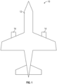
- the aircraft 10 includes an airframe 12 and one or more engines 14, for example gas turbine engines 14, to provide propulsion for the aircraft 10.
- the engines 14 are each enclosed in a nacelle 16.
- the nacelle 16 defines an engine compartment 18 at least partially surrounding the engine 14 between an outer casing surface 20 of the engine 14 and an inner nacelle surface 22 of the nacelle 16.
- One or more flame detectors 24 are located in the engine compartment 18, for example in a compartment wall 26 of the engine compartment 18 and are configured to detect the presence of fire in the engine compartment 18.
- the flame detector 24 detects emissions of infrared radiation in the engine compartment 18 from, for example, a fire 28.
- the flame detector 24 includes a first sensor 30 and a second sensor 32 disposed in a detector housing 34.
- the first sensor is configured to detect light emissions in a first infrared wavelength range
- the second sensor is configured to detect light emissions at a second wavelength range, different from the first wavelength range.
- the second wavelength range may be an infrared wavelength range
- the second wavelength range may be, for example, an ultraviolet wavelength range.
- the second sensor In some embodiments the detector housing 34 is cylindrical having a housing body 36 and a first end 38 and second end 40. In the illustrated embodiment the first sensor 30 and the second sensor 32 are located in the first end 38 at a first sensor window 42 and a second sensor window 44, respectively.
- first sensor 30 and the second sensor 32 are located at the first end 38, in other embodiments the sensors 30 and 32 may be located in the housing body 36. In another embodiment, illustrated in FIG. 4 , the first sensor 30 and the second sensor 32 share a common sensor window 46.
- the sensors 30, 32 are positioned side-by-side at the first end 38.
- the sensors 30, 32 may have different relative positions.
- the first sensor 30 is configured to detect emissions having a 4.3-4.4 micron wavelength signature.
- the infrared sensor 32 may be configured to detect emissions having a different wavelength signature, for example 0.88 microns.
- the second sensor 32 may be configured to detect ultraviolet light signals.
- the flame detector 24 includes a controller 48, which in some embodiments is located in the detector housing 34. One skilled in the art will readily appreciate, however, that in some embodiments the controller 48 may be located remotely, outside of the detector housing 34.
- the controller 48 is operably connected the first sensor 30 and the second sensor 32 to receive and evaluate signals from the first sensor 30 and the second sensor 32.
- the controller 48 includes control logic, which receives signals from the first sensor 30 and the second sensor 32 in a potential flame detection event.
- the control logic must receive detection signals from both the first sensor 30 and the second sensor 32 in order to positively identify the event as a flame detection.
- the controller 48 will then trigger one or more alerts or alarms, such as lights or audible alarms to alert the flight crew to the flame detection. This requirement of positive flame detection signals from both the first sensor 30 and the second sensor 32 before triggering alerts or alarms significantly reduces the occurrence of false alarms.
- the flame detector 24 further may include an internal light source, such as a light emitting diode (LED) 50 in the detector housing 34.
- LED 50 is connected to the controller 48 and allows for periodic self test of the flame detector 24 to ensure that the flame detector 24 is functioning properly.
- the LED 50 emits signals in the detection range of the first sensor 30 and the second sensor 32.
- the first sensor 30 and the second sensor 32 detect the light signal emitted from the LED 50 and in turn signal the controller 48. Once the signals are received at the controller from both the first sensor 30 and the second sensor 32, the test is complete and the determination is made by the controller 48 that the flame detector 24 is operating properly.
- the LED 50 may emit light signals only detectable by one of the sensors 30 or, 32 such that if the controller 48 receives detection signals from both of the sensors 30, 32, the test is unsuccessful and the flame detector 24 is not operating properly.
- the controller 48 will initiate the test periodically based on, for example, a time-based schedule, or the test may be initiated remotely by, for example, flight crew or maintenance personnel.
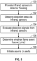
- the sensors 30, 32 are provided in the detector housing 34.
- the first sensor 30 observes a detection area and the second sensor 32 observes the same detection area.
- the controller 48 evaluates signals received from the first sensor 30 and the second sensor 32. If flame detection signals are received from both the first sensor 30 and the second sensor 32, the controller 48 determines that a flame event has occurred at block 106. If a flame event is detected at block 106, the controller 48 initiates one or more alerts or alarms at block 108.
- the flame detector 24 configurations disclosed herein reduce the occurrence of false alarms thus improving flight crew confidence in the flame detector 24. Further, the flame detector 24 allows for a self-test via inclusion of the LED 50. Further, in some embodiments the flame detector 24 can simply replace a prior art flame detector via retrofit, by packaging the sensors 30, 32 into the housing 34, which is a same size as a prior art housing.
Landscapes
- Physics & Mathematics (AREA)
- General Physics & Mathematics (AREA)
- Business, Economics & Management (AREA)
- Emergency Management (AREA)
- Engineering & Computer Science (AREA)
- Computer Security & Cryptography (AREA)
- Health & Medical Sciences (AREA)
- Public Health (AREA)
- Spectroscopy & Molecular Physics (AREA)
- Fire-Detection Mechanisms (AREA)
- Photometry And Measurement Of Optical Pulse Characteristics (AREA)
- Fire Alarms (AREA)
Abstract
Description
- Exemplary embodiments pertain to the art of aircraft, and more particularly to optical flame detectors utilized in engine compartments of aircraft.
- Flame detectors are utilized in aircraft in locations such as engine compartments to detect fire in the engine compartment. Present flame detectors utilized in, for example, helicopters or fixed wing aircraft especially, are prone to false alarms in which the detector indicates the presence of a fire where none exists. The main sources of such false alarms are temperature variation of hot surfaces on which the detector is focused, and temperature fluctuations in the engine compartment due to engine exhaust leaks and/or engine exhaust reingestion.
- The possibility and occurrence of false alarms creates a significant additional burden on the flight crew of the aircraft and impacts their confidence in the system. This can lead to ignored alarms or execution of emergency procedures when a true fire hazard or other unsafe conditions does not actually exist. The false indication of a fire may lead a crew to land the aircraft in unsafe conditions, resulting in injuries and/or damage to the aircraft.
- In one embodiment, a flame detector for an aircraft includes a housing and two sensors positioned in the housing to detect light signals indicative of a flame event. The two sensors include a first sensor configured to detect light signals in at a first infrared wavelength range, and a second sensor configured to detect light signals at a second wavelength range. A controller is configured to receive signals from the two sensors, and to determine the presence of the flame event only if the signals indicative of the flame event are received from both of the two sensors.
- Additionally or alternatively, in this or other embodiments, the two sensors detect emissions having different wavelength signatures.
- Additionally or alternatively, in this or other embodiments, a first sensor of the two infrared sensors is configured to detect infrared emissions having a 4.3-4.4 micron signature.
- Additionally or alternatively, in this or other embodiments, a second sensor of the two sensors is configured to detect emissions having a 0.88 micron signature.
- Additionally or alternatively, in this or other embodiments, the two sensors share a common window in the housing.
- Additionally or alternatively, in this or other embodiments, a light source is positioned in the housing to emit light signals for test of the flame detector.
- Additionally or alternatively, in this or other embodiments, the controller is positioned in the housing.
- In another embodiment, a flame detector system or an aircraft includes an engine located in an engine compartment, and a flame detector located in the engine compartment. The flame detector includes a housing and two sensors located in the housing to detect light signals indicative of a flame event. The two sensors include a first sensor configured to detect light signals in at a first infrared wavelength range, and a second sensor configured to detect light signals at a second wavelength range. A controller is configured to receive signals from the two sensors, and to determine the presence of the flame event only if signals indicative of the flame event are received from both of the two sensors.
- Additionally or alternatively, in this or other embodiments, the two sensors detect emissions having different wavelength signatures.
- Additionally or alternatively, in this or other embodiments, a first sensor of the two sensors is configured to detect infrared emissions having a 4.3-4.4 micron signature.
- Additionally or alternatively, in this or other embodiments, a second sensor of the two sensors is configured to detect emissions having a 0.88 micron signature.
- Additionally or alternatively, in this or other embodiments, the two sensors share a common window in the housing.
- Additionally or alternatively, in this or other embodiments, a light source is positioned in the housing to emit light signals for test of the flame detector.
- Additionally or alternatively, in this or other embodiments, the controller is located in the housing.
- In yet another embodiment, a method of detecting a flame event includes providing two sensors in a detector housing. The two sensors include a first sensor configured to detect light signals in at a first infrared wavelength range, and a second sensor configured to detect light signals at a second wavelength range. A detection area is observed via the two sensors, and detection signals received from the two sensors are evaluated at a controller. The presence of a flame event is determined only if detection signals are received from both of the two sensors.
- Additionally or alternatively, in this or other embodiments, one or more alarms or alerts are initiated when the presence of a flame event is determined.
- Additionally or alternatively, in this or other embodiments, the two sensors detect emissions having different wavelength signatures.
- Additionally or alternatively, in this or other embodiments, a first sensor of the two sensors is configured to detect infrared emissions having a 4.3-4.4 micron signature.
- Additionally or alternatively, in this or other embodiments, a second sensor of the two sensors is configured to detect emissions having a 0.88 micron signature.
- Additionally or alternatively, in this or other embodiments, the flame detector is tested via a light source located in the housing.
- The following descriptions should not be considered limiting in any way. With reference to the accompanying drawings, like elements are numbered alike:
-
FIG. 1 is a schematic illustration of an embodiment of an aircraft -
FIG. 2 is a schematic illustration of an embodiment of an engine compartment of an aircraft; -
FIG. 3 is a schematic illustration of an embodiment of an infrared flame detector; -
FIG. 4 is a schematic illustration of another embodiment of an infrared flame detector; -
FIG. 5 is a schematic illustration of an embodiment of a method of operating an infrared flame detector; - A detailed description of one or more embodiments of the disclosed apparatus and method are presented herein by way of exemplification and not limitation with reference to the Figures.
- Referring to
FIG. 1 , illustrated is an embodiment of anaircraft 10. Theaircraft 10 includes anairframe 12 and one ormore engines 14, for examplegas turbine engines 14, to provide propulsion for theaircraft 10. Referring now to the cross-sectional view ofFIG. 2 , theengines 14 are each enclosed in anacelle 16. Thenacelle 16 defines anengine compartment 18 at least partially surrounding theengine 14 between anouter casing surface 20 of theengine 14 and aninner nacelle surface 22 of thenacelle 16. One ormore flame detectors 24 are located in theengine compartment 18, for example in acompartment wall 26 of theengine compartment 18 and are configured to detect the presence of fire in theengine compartment 18. Theflame detector 24 detects emissions of infrared radiation in theengine compartment 18 from, for example, afire 28. - Referring now to
FIG. 3 , theflame detector 24 includes afirst sensor 30 and asecond sensor 32 disposed in adetector housing 34. The first sensor is configured to detect light emissions in a first infrared wavelength range, and the second sensor is configured to detect light emissions at a second wavelength range, different from the first wavelength range. While in some embodiments, the second wavelength range may be an infrared wavelength range, in other embodiment the second wavelength range may be, for example, an ultraviolet wavelength range. The second sensor In some embodiments thedetector housing 34 is cylindrical having ahousing body 36 and afirst end 38 andsecond end 40. In the illustrated embodiment thefirst sensor 30 and thesecond sensor 32 are located in thefirst end 38 at afirst sensor window 42 and asecond sensor window 44, respectively. While in the illustrated embodiment thefirst sensor 30 and thesecond sensor 32 are located at thefirst end 38, in other embodiments thesensors housing body 36. In another embodiment, illustrated inFIG. 4 , thefirst sensor 30 and thesecond sensor 32 share acommon sensor window 46. - Referring again to
FIG. 3 , thesensors first end 38. In other embodiments, on the other hand, thesensors - The
first sensor 30 is configured to detect emissions having a 4.3-4.4 micron wavelength signature. Theinfrared sensor 32 may be configured to detect emissions having a different wavelength signature, for example 0.88 microns. In some embodiments thesecond sensor 32 may be configured to detect ultraviolet light signals. Theflame detector 24 includes acontroller 48, which in some embodiments is located in thedetector housing 34. One skilled in the art will readily appreciate, however, that in some embodiments thecontroller 48 may be located remotely, outside of thedetector housing 34. Thecontroller 48 is operably connected thefirst sensor 30 and thesecond sensor 32 to receive and evaluate signals from thefirst sensor 30 and thesecond sensor 32. Thecontroller 48 includes control logic, which receives signals from thefirst sensor 30 and thesecond sensor 32 in a potential flame detection event. The control logic must receive detection signals from both thefirst sensor 30 and thesecond sensor 32 in order to positively identify the event as a flame detection. Thecontroller 48 will then trigger one or more alerts or alarms, such as lights or audible alarms to alert the flight crew to the flame detection. This requirement of positive flame detection signals from both thefirst sensor 30 and thesecond sensor 32 before triggering alerts or alarms significantly reduces the occurrence of false alarms. - The
flame detector 24 further may include an internal light source, such as a light emitting diode (LED) 50 in thedetector housing 34. ThisLED 50 is connected to thecontroller 48 and allows for periodic self test of theflame detector 24 to ensure that theflame detector 24 is functioning properly. To perform the test, theLED 50 emits signals in the detection range of thefirst sensor 30 and thesecond sensor 32. Thefirst sensor 30 and thesecond sensor 32 detect the light signal emitted from theLED 50 and in turn signal thecontroller 48. Once the signals are received at the controller from both thefirst sensor 30 and thesecond sensor 32, the test is complete and the determination is made by thecontroller 48 that theflame detector 24 is operating properly. In some configurations, theLED 50 may emit light signals only detectable by one of thesensors controller 48 receives detection signals from both of thesensors flame detector 24 is not operating properly. In some configurations, thecontroller 48 will initiate the test periodically based on, for example, a time-based schedule, or the test may be initiated remotely by, for example, flight crew or maintenance personnel. - Referring now to
FIG. 5 and with continued reference toFIG. 4 , illustrated is a method of operation of theflame detector 24. Atblock 100, thesensors detector housing 34. Atblock 102, thefirst sensor 30 observes a detection area and thesecond sensor 32 observes the same detection area. Atblock 104, thecontroller 48 evaluates signals received from thefirst sensor 30 and thesecond sensor 32. If flame detection signals are received from both thefirst sensor 30 and thesecond sensor 32, thecontroller 48 determines that a flame event has occurred atblock 106. If a flame event is detected atblock 106, thecontroller 48 initiates one or more alerts or alarms atblock 108. - The
flame detector 24 configurations disclosed herein reduce the occurrence of false alarms thus improving flight crew confidence in theflame detector 24. Further, theflame detector 24 allows for a self-test via inclusion of theLED 50. Further, in some embodiments theflame detector 24 can simply replace a prior art flame detector via retrofit, by packaging thesensors housing 34, which is a same size as a prior art housing. - The term "about" is intended to include the degree of error associated with measurement of the particular quantity based upon the equipment available at the time of filing the application.
- The terminology used herein is for the purpose of describing particular embodiments only and is not intended to be limiting of the present disclosure. As used herein, the singular forms "a", "an" and "the" are intended to include the plural forms as well, unless the context clearly indicates otherwise. It will be further understood that the terms "comprises" and/or "comprising," when used in this specification, specify the presence of stated features, integers, steps, operations, elements, and/or components, but do not preclude the presence or addition of one or more other features, integers, steps, operations, element components, and/or groups thereof.
- While the present disclosure has been described with reference to an exemplary embodiment or embodiments, it will be understood by those skilled in the art that various changes may be made and equivalents may be substituted for elements thereof without departing from the scope of the present disclosure. In addition, many modifications may be made to adapt a particular situation or material to the teachings of the present disclosure without departing from the essential scope thereof. Therefore, it is intended that the present disclosure not be limited to the particular embodiment disclosed as the best mode contemplated for carrying out this present disclosure, but that the present disclosure will include all embodiments falling within the scope of the claims.
Claims (14)
- A flame detector for an aircraft, comprising:a housing;two sensors disposed in the housing to detect light signals indicative of a flame event, the two sensors including:a first sensor configured to detect light signals at a first infrared wavelength range; anda second sensor configured to detect light signals at a second wavelength range; anda controller to receive signals from the two sensors, and to determine the presence of the flame event only if the signals indicative of the flame event are received from both of the two sensors.
- The flame detector of claim 1, wherein the two sensors detect emissions having different wavelength signatures.
- The flame detector of claim 1 or 2, wherein a first sensor of the two infrared sensors is configured to detect infrared emissions having a 4.3-4.4 micron signature.
- The flame detector of claim 3, wherein a second sensor of the two sensors is configured to detect emissions having a 0.88 micron signature.
- The flame detector of any preceding claim, wherein the two sensors share a common window in the housing.
- The flame detector of any preceding claim, further comprising a light source disposed in the housing to emit light signals for test of the flame detector.
- The flame detector of any preceding claim, wherein the controller is disposed in the housing.
- A flame detector system of an aircraft, comprising:an engine disposed in an engine compartment; anda flame detector disposed in the engine compartment, wherein the flame detector is a flame detector as claimed in any preceding claim.
- A method of detecting a flame event, comprising:
providing two sensors in a detector housing, the two sensors including:a first sensor configured to detect light signals at a first infrared wavelength range; anda second sensor configured to detect light signals at a second wavelength range;observing a detection area via the two sensors;evaluating detection signals received from the two sensors at a controller; anddetermining the presence of a flame event only if detection signals are received from both of the two sensors. - The method of claim 9, further comprising initiating one or more alarms or alerts when the presence of a flame event is determined.
- The method of claim 9 or 10, wherein the two sensors detect emissions having different wavelength signatures.
- The method of claim 9, 10 or 11, wherein a first sensor of the two sensors is configured to detect infrared emissions having a 4.3-4.4 micron signature.
- The method of claim 12, wherein a second sensor of the two sensors is configured to detect emissions having a 0.88 micron signature.
- The method of any one of claims 9-13, further comprising testing the flame detector via a light source disposed in the housing.
Applications Claiming Priority (1)
| Application Number | Priority Date | Filing Date | Title |
|---|---|---|---|
| US18/157,924 US12437623B2 (en) | 2023-01-23 | 2023-01-23 | Dual band infra red optical fire detector |
Publications (1)
| Publication Number | Publication Date |
|---|---|
| EP4411683A1 true EP4411683A1 (en) | 2024-08-07 |
Family
ID=89707836
Family Applications (1)
| Application Number | Title | Priority Date | Filing Date |
|---|---|---|---|
| EP24153371.0A Pending EP4411683A1 (en) | 2023-01-23 | 2024-01-23 | Dual band infra red optical fire detector |
Country Status (2)
| Country | Link |
|---|---|
| US (1) | US12437623B2 (en) |
| EP (1) | EP4411683A1 (en) |
Families Citing this family (1)
| Publication number | Priority date | Publication date | Assignee | Title |
|---|---|---|---|---|
| US20260092811A1 (en) * | 2024-09-30 | 2026-04-02 | Spectronix Ltd. | Multi-spectral optical detector with integrated test |
Citations (5)
| Publication number | Priority date | Publication date | Assignee | Title |
|---|---|---|---|---|
| US4249168A (en) * | 1978-04-25 | 1981-02-03 | Cerberus Ag | Flame detector |
| US4296324A (en) * | 1979-11-02 | 1981-10-20 | Santa Barbara Research Center | Dual spectrum infrared fire sensor |
| US4529881A (en) * | 1982-03-02 | 1985-07-16 | Pyrotector, Inc. | Flame detector with test lamp and adjustable field of view |
| US4701624A (en) * | 1985-10-31 | 1987-10-20 | Santa Barbara Research Center | Fire sensor system utilizing optical fibers for remote sensing |
| US5051590A (en) * | 1989-12-06 | 1991-09-24 | Santa Barbara Research Center | Fiber optic flame detection and temperature measurement system having one or more in-line temperature dependent optical filters |
Family Cites Families (10)
| Publication number | Priority date | Publication date | Assignee | Title |
|---|---|---|---|---|
| US4583597A (en) | 1978-02-27 | 1986-04-22 | Dov Spector | Fire and explosion detection and suppression system |
| US4206454A (en) | 1978-05-08 | 1980-06-03 | Chloride Incorporated | Two channel optical flame detector |
| JPH0754557B2 (en) | 1982-09-20 | 1995-06-07 | サンタバーバラ・リサーチ・センター | Fire identification sensor with heat-sensitive auxiliary drive capability |
| WO1993018494A1 (en) | 1992-03-11 | 1993-09-16 | The Boeing Company | Thermal condition sensor system for monitoring equipment operation |
| US5850182A (en) | 1997-01-07 | 1998-12-15 | Detector Electronics Corporation | Dual wavelength fire detection method and apparatus |
| US5995008A (en) | 1997-05-07 | 1999-11-30 | Detector Electronics Corporation | Fire detection method and apparatus using overlapping spectral bands |
| US7505604B2 (en) | 2002-05-20 | 2009-03-17 | Simmonds Precision Prodcuts, Inc. | Method for detection and recognition of fog presence within an aircraft compartment using video images |
| US7511276B2 (en) | 2007-01-22 | 2009-03-31 | Brunswick Corporation | Heat source sensor for a marine vessel |
| US7638770B2 (en) | 2007-03-22 | 2009-12-29 | Spectronix Ltd. | Method for detecting a fire condition in a monitored region |
| GB2544040B (en) | 2015-10-19 | 2018-03-14 | Ffe Ltd | Improvements in or relating to flame detectors and associated methods |
-
2023
- 2023-01-23 US US18/157,924 patent/US12437623B2/en active Active
-
2024
- 2024-01-23 EP EP24153371.0A patent/EP4411683A1/en active Pending
Patent Citations (5)
| Publication number | Priority date | Publication date | Assignee | Title |
|---|---|---|---|---|
| US4249168A (en) * | 1978-04-25 | 1981-02-03 | Cerberus Ag | Flame detector |
| US4296324A (en) * | 1979-11-02 | 1981-10-20 | Santa Barbara Research Center | Dual spectrum infrared fire sensor |
| US4529881A (en) * | 1982-03-02 | 1985-07-16 | Pyrotector, Inc. | Flame detector with test lamp and adjustable field of view |
| US4701624A (en) * | 1985-10-31 | 1987-10-20 | Santa Barbara Research Center | Fire sensor system utilizing optical fibers for remote sensing |
| US5051590A (en) * | 1989-12-06 | 1991-09-24 | Santa Barbara Research Center | Fiber optic flame detection and temperature measurement system having one or more in-line temperature dependent optical filters |
Also Published As
| Publication number | Publication date |
|---|---|
| US20240249607A1 (en) | 2024-07-25 |
| US12437623B2 (en) | 2025-10-07 |
Similar Documents
| Publication | Publication Date | Title |
|---|---|---|
| US9751635B2 (en) | Indicating device for indicating an activation status of an escape slide in an aircraft | |
| US20150297930A1 (en) | Temperature derivative based launch method for fire suppression systems | |
| CN105092047B (en) | Overheat sensor system | |
| JP6013027B2 (en) | Fire alarm system, fire alarm method for fire alarm system, and fire alarm program for fire alarm system | |
| US8265805B2 (en) | Method and apparatus for detecting icing conditions for an aircraft | |
| US12437623B2 (en) | Dual band infra red optical fire detector | |
| CA1323433C (en) | Engine monitoring apparatus | |
| US10442519B2 (en) | Indication device as well as door arrangement and aircraft with such an indication device | |
| EP3399509A1 (en) | Airplane fire detection system | |
| EP0038856A1 (en) | Dual spectrum infared fire sensor | |
| US20080150763A1 (en) | Method and Device for Detecting, on the Ground, the Obstruction of a Pressure Tap of a Static Pressure Sensor of an Aircraft | |
| US20220058939A1 (en) | Smoke Detector Availability Test | |
| JP7268999B2 (en) | Fire detector and tunnel disaster prevention system | |
| EP3428591B1 (en) | Flame detector field of view verification via reverse infrared signaling | |
| EP3074737B1 (en) | Ultraviolet light flame detector | |
| US11423752B2 (en) | Fire detection in an occupied compartment | |
| US12380787B2 (en) | Fire detection or early warning using gases | |
| KR100927385B1 (en) | Vehicle fire detector with self-check using wavelength band detection | |
| KR102112691B1 (en) | System for detecting fire | |
| US20220082362A1 (en) | Method of validating a shock tube event | |
| CN207489201U (en) | A kind of power battery cabin fire detection automatic alarm system | |
| KR102057998B1 (en) | Fire detector for vehicle | |
| CN110473377A (en) | A kind of intelligence aviation fire hazard monitoring system | |
| US20160059968A1 (en) | Method and device for distinguishing between the in-flight status and the on-ground status of an aircraft | |
| CN206311577U (en) | A kind of anti-gas-detecting device for blocking |
Legal Events
| Date | Code | Title | Description |
|---|---|---|---|
| PUAI | Public reference made under article 153(3) epc to a published international application that has entered the european phase |
Free format text: ORIGINAL CODE: 0009012 |
|
| STAA | Information on the status of an ep patent application or granted ep patent |
Free format text: STATUS: THE APPLICATION HAS BEEN PUBLISHED |
|
| AK | Designated contracting states |
Kind code of ref document: A1 Designated state(s): AL AT BE BG CH CY CZ DE DK EE ES FI FR GB GR HR HU IE IS IT LI LT LU LV MC ME MK MT NL NO PL PT RO RS SE SI SK SM TR |
|
| STAA | Information on the status of an ep patent application or granted ep patent |
Free format text: STATUS: REQUEST FOR EXAMINATION WAS MADE |
|
| 17P | Request for examination filed |
Effective date: 20250206 |
|
| GRAP | Despatch of communication of intention to grant a patent |
Free format text: ORIGINAL CODE: EPIDOSNIGR1 |
|
| STAA | Information on the status of an ep patent application or granted ep patent |
Free format text: STATUS: GRANT OF PATENT IS INTENDED |
|
| RIC1 | Information provided on ipc code assigned before grant |
Ipc: G08B 17/12 20060101AFI20260624BHEP Ipc: G08B 29/18 20060101ALI20260624BHEP Ipc: A62C 3/08 20060101ALI20260624BHEP Ipc: G01J 5/00 20220101ALI20260624BHEP Ipc: G08B 29/14 20060101ALI20260624BHEP Ipc: B64D 45/00 20060101ALN20260624BHEP |
|
| INTG | Intention to grant announced |
Effective date: 20260706 |