EP4411624A1 - Liquefied gas monitoring system - Google Patents
Liquefied gas monitoring system Download PDFInfo
- Publication number
- EP4411624A1 EP4411624A1 EP22876099.7A EP22876099A EP4411624A1 EP 4411624 A1 EP4411624 A1 EP 4411624A1 EP 22876099 A EP22876099 A EP 22876099A EP 4411624 A1 EP4411624 A1 EP 4411624A1
- Authority
- EP
- European Patent Office
- Prior art keywords
- liquefied gas
- container
- fed
- liquid level
- gas
- Prior art date
- Legal status (The legal status is an assumption and is not a legal conclusion. Google has not performed a legal analysis and makes no representation as to the accuracy of the status listed.)
- Pending
Links
Images


Classifications
-
- F—MECHANICAL ENGINEERING; LIGHTING; HEATING; WEAPONS; BLASTING
- F17—STORING OR DISTRIBUTING GASES OR LIQUIDS
- F17C—VESSELS FOR CONTAINING OR STORING COMPRESSED, LIQUEFIED OR SOLIDIFIED GASES; FIXED-CAPACITY GAS-HOLDERS; FILLING VESSELS WITH, OR DISCHARGING FROM VESSELS, COMPRESSED, LIQUEFIED, OR SOLIDIFIED GASES
- F17C13/00—Details of vessels or of the filling or discharging of vessels
- F17C13/02—Special adaptations of indicating, measuring, or monitoring equipment
- F17C13/021—Special adaptations of indicating, measuring, or monitoring equipment having the height as the parameter
-
- G—PHYSICS
- G06—COMPUTING OR CALCULATING; COUNTING
- G06Q—INFORMATION AND COMMUNICATION TECHNOLOGY [ICT] SPECIALLY ADAPTED FOR ADMINISTRATIVE, COMMERCIAL, FINANCIAL, MANAGERIAL OR SUPERVISORY PURPOSES; SYSTEMS OR METHODS SPECIALLY ADAPTED FOR ADMINISTRATIVE, COMMERCIAL, FINANCIAL, MANAGERIAL OR SUPERVISORY PURPOSES, NOT OTHERWISE PROVIDED FOR
- G06Q50/00—Information and communication technology [ICT] specially adapted for implementation of business processes of specific business sectors, e.g. utilities or tourism
- G06Q50/06—Energy or water supply
-
- F—MECHANICAL ENGINEERING; LIGHTING; HEATING; WEAPONS; BLASTING
- F17—STORING OR DISTRIBUTING GASES OR LIQUIDS
- F17C—VESSELS FOR CONTAINING OR STORING COMPRESSED, LIQUEFIED OR SOLIDIFIED GASES; FIXED-CAPACITY GAS-HOLDERS; FILLING VESSELS WITH, OR DISCHARGING FROM VESSELS, COMPRESSED, LIQUEFIED, OR SOLIDIFIED GASES
- F17C13/00—Details of vessels or of the filling or discharging of vessels
- F17C13/02—Special adaptations of indicating, measuring, or monitoring equipment
- F17C13/023—Special adaptations of indicating, measuring, or monitoring equipment having the mass as the parameter
-
- F—MECHANICAL ENGINEERING; LIGHTING; HEATING; WEAPONS; BLASTING
- F17—STORING OR DISTRIBUTING GASES OR LIQUIDS
- F17C—VESSELS FOR CONTAINING OR STORING COMPRESSED, LIQUEFIED OR SOLIDIFIED GASES; FIXED-CAPACITY GAS-HOLDERS; FILLING VESSELS WITH, OR DISCHARGING FROM VESSELS, COMPRESSED, LIQUEFIED, OR SOLIDIFIED GASES
- F17C13/00—Details of vessels or of the filling or discharging of vessels
- F17C13/02—Special adaptations of indicating, measuring, or monitoring equipment
- F17C13/025—Special adaptations of indicating, measuring, or monitoring equipment having the pressure as the parameter
-
- F—MECHANICAL ENGINEERING; LIGHTING; HEATING; WEAPONS; BLASTING
- F17—STORING OR DISTRIBUTING GASES OR LIQUIDS
- F17C—VESSELS FOR CONTAINING OR STORING COMPRESSED, LIQUEFIED OR SOLIDIFIED GASES; FIXED-CAPACITY GAS-HOLDERS; FILLING VESSELS WITH, OR DISCHARGING FROM VESSELS, COMPRESSED, LIQUEFIED, OR SOLIDIFIED GASES
- F17C13/00—Details of vessels or of the filling or discharging of vessels
- F17C13/02—Special adaptations of indicating, measuring, or monitoring equipment
- F17C13/026—Special adaptations of indicating, measuring, or monitoring equipment having the temperature as the parameter
-
- F—MECHANICAL ENGINEERING; LIGHTING; HEATING; WEAPONS; BLASTING
- F17—STORING OR DISTRIBUTING GASES OR LIQUIDS
- F17C—VESSELS FOR CONTAINING OR STORING COMPRESSED, LIQUEFIED OR SOLIDIFIED GASES; FIXED-CAPACITY GAS-HOLDERS; FILLING VESSELS WITH, OR DISCHARGING FROM VESSELS, COMPRESSED, LIQUEFIED, OR SOLIDIFIED GASES
- F17C3/00—Vessels not under pressure
- F17C3/02—Vessels not under pressure with provision for thermal insulation
-
- F—MECHANICAL ENGINEERING; LIGHTING; HEATING; WEAPONS; BLASTING
- F17—STORING OR DISTRIBUTING GASES OR LIQUIDS
- F17C—VESSELS FOR CONTAINING OR STORING COMPRESSED, LIQUEFIED OR SOLIDIFIED GASES; FIXED-CAPACITY GAS-HOLDERS; FILLING VESSELS WITH, OR DISCHARGING FROM VESSELS, COMPRESSED, LIQUEFIED, OR SOLIDIFIED GASES
- F17C5/00—Methods or apparatus for filling containers with liquefied, solidified, or compressed gases under pressures
- F17C5/02—Methods or apparatus for filling containers with liquefied, solidified, or compressed gases under pressures for filling with liquefied gases
-
- G—PHYSICS
- G01—MEASURING; TESTING
- G01D—MEASURING NOT SPECIALLY ADAPTED FOR A SPECIFIC VARIABLE; ARRANGEMENTS FOR MEASURING TWO OR MORE VARIABLES NOT COVERED IN A SINGLE OTHER SUBCLASS; TARIFF METERING APPARATUS; MEASURING OR TESTING NOT OTHERWISE PROVIDED FOR
- G01D21/00—Measuring or testing not otherwise provided for
- G01D21/02—Measuring two or more variables by means not covered by a single other subclass
-
- G—PHYSICS
- G01—MEASURING; TESTING
- G01L—MEASURING FORCE, STRESS, TORQUE, WORK, MECHANICAL POWER, MECHANICAL EFFICIENCY, OR FLUID PRESSURE
- G01L9/00—Measuring steady of quasi-steady pressure of fluid or fluent solid material by electric or magnetic pressure-sensitive elements; Transmitting or indicating the displacement of mechanical pressure-sensitive elements, used to measure the steady or quasi-steady pressure of a fluid or fluent solid material, by electric or magnetic means
- G01L9/12—Measuring steady of quasi-steady pressure of fluid or fluent solid material by electric or magnetic pressure-sensitive elements; Transmitting or indicating the displacement of mechanical pressure-sensitive elements, used to measure the steady or quasi-steady pressure of a fluid or fluent solid material, by electric or magnetic means by making use of variations in capacitance, i.e. electric circuits therefor
-
- G—PHYSICS
- G06—COMPUTING OR CALCULATING; COUNTING
- G06Q—INFORMATION AND COMMUNICATION TECHNOLOGY [ICT] SPECIALLY ADAPTED FOR ADMINISTRATIVE, COMMERCIAL, FINANCIAL, MANAGERIAL OR SUPERVISORY PURPOSES; SYSTEMS OR METHODS SPECIALLY ADAPTED FOR ADMINISTRATIVE, COMMERCIAL, FINANCIAL, MANAGERIAL OR SUPERVISORY PURPOSES, NOT OTHERWISE PROVIDED FOR
- G06Q30/00—Commerce
- G06Q30/018—Certifying business or products
-
- G—PHYSICS
- G06—COMPUTING OR CALCULATING; COUNTING
- G06Q—INFORMATION AND COMMUNICATION TECHNOLOGY [ICT] SPECIALLY ADAPTED FOR ADMINISTRATIVE, COMMERCIAL, FINANCIAL, MANAGERIAL OR SUPERVISORY PURPOSES; SYSTEMS OR METHODS SPECIALLY ADAPTED FOR ADMINISTRATIVE, COMMERCIAL, FINANCIAL, MANAGERIAL OR SUPERVISORY PURPOSES, NOT OTHERWISE PROVIDED FOR
- G06Q50/00—Information and communication technology [ICT] specially adapted for implementation of business processes of specific business sectors, e.g. utilities or tourism
- G06Q50/10—Services
-
- F—MECHANICAL ENGINEERING; LIGHTING; HEATING; WEAPONS; BLASTING
- F17—STORING OR DISTRIBUTING GASES OR LIQUIDS
- F17C—VESSELS FOR CONTAINING OR STORING COMPRESSED, LIQUEFIED OR SOLIDIFIED GASES; FIXED-CAPACITY GAS-HOLDERS; FILLING VESSELS WITH, OR DISCHARGING FROM VESSELS, COMPRESSED, LIQUEFIED, OR SOLIDIFIED GASES
- F17C2221/00—Handled fluid, in particular type of fluid
- F17C2221/01—Pure fluids
- F17C2221/012—Hydrogen
-
- F—MECHANICAL ENGINEERING; LIGHTING; HEATING; WEAPONS; BLASTING
- F17—STORING OR DISTRIBUTING GASES OR LIQUIDS
- F17C—VESSELS FOR CONTAINING OR STORING COMPRESSED, LIQUEFIED OR SOLIDIFIED GASES; FIXED-CAPACITY GAS-HOLDERS; FILLING VESSELS WITH, OR DISCHARGING FROM VESSELS, COMPRESSED, LIQUEFIED, OR SOLIDIFIED GASES
- F17C2221/00—Handled fluid, in particular type of fluid
- F17C2221/03—Mixtures
- F17C2221/032—Hydrocarbons
- F17C2221/033—Methane, e.g. natural gas, CNG, LNG, GNL, GNC, PLNG
-
- F—MECHANICAL ENGINEERING; LIGHTING; HEATING; WEAPONS; BLASTING
- F17—STORING OR DISTRIBUTING GASES OR LIQUIDS
- F17C—VESSELS FOR CONTAINING OR STORING COMPRESSED, LIQUEFIED OR SOLIDIFIED GASES; FIXED-CAPACITY GAS-HOLDERS; FILLING VESSELS WITH, OR DISCHARGING FROM VESSELS, COMPRESSED, LIQUEFIED, OR SOLIDIFIED GASES
- F17C2223/00—Handled fluid before transfer, i.e. state of fluid when stored in the vessel or before transfer from the vessel
- F17C2223/01—Handled fluid before transfer, i.e. state of fluid when stored in the vessel or before transfer from the vessel characterised by the phase
- F17C2223/0146—Two-phase
- F17C2223/0153—Liquefied gas, e.g. LPG, GPL
- F17C2223/0161—Liquefied gas, e.g. LPG, GPL cryogenic, e.g. LNG, GNL, PLNG
-
- F—MECHANICAL ENGINEERING; LIGHTING; HEATING; WEAPONS; BLASTING
- F17—STORING OR DISTRIBUTING GASES OR LIQUIDS
- F17C—VESSELS FOR CONTAINING OR STORING COMPRESSED, LIQUEFIED OR SOLIDIFIED GASES; FIXED-CAPACITY GAS-HOLDERS; FILLING VESSELS WITH, OR DISCHARGING FROM VESSELS, COMPRESSED, LIQUEFIED, OR SOLIDIFIED GASES
- F17C2223/00—Handled fluid before transfer, i.e. state of fluid when stored in the vessel or before transfer from the vessel
- F17C2223/03—Handled fluid before transfer, i.e. state of fluid when stored in the vessel or before transfer from the vessel characterised by the pressure level
- F17C2223/033—Small pressure, e.g. for liquefied gas
-
- F—MECHANICAL ENGINEERING; LIGHTING; HEATING; WEAPONS; BLASTING
- F17—STORING OR DISTRIBUTING GASES OR LIQUIDS
- F17C—VESSELS FOR CONTAINING OR STORING COMPRESSED, LIQUEFIED OR SOLIDIFIED GASES; FIXED-CAPACITY GAS-HOLDERS; FILLING VESSELS WITH, OR DISCHARGING FROM VESSELS, COMPRESSED, LIQUEFIED, OR SOLIDIFIED GASES
- F17C2223/00—Handled fluid before transfer, i.e. state of fluid when stored in the vessel or before transfer from the vessel
- F17C2223/04—Handled fluid before transfer, i.e. state of fluid when stored in the vessel or before transfer from the vessel characterised by other properties of handled fluid before transfer
-
- F—MECHANICAL ENGINEERING; LIGHTING; HEATING; WEAPONS; BLASTING
- F17—STORING OR DISTRIBUTING GASES OR LIQUIDS
- F17C—VESSELS FOR CONTAINING OR STORING COMPRESSED, LIQUEFIED OR SOLIDIFIED GASES; FIXED-CAPACITY GAS-HOLDERS; FILLING VESSELS WITH, OR DISCHARGING FROM VESSELS, COMPRESSED, LIQUEFIED, OR SOLIDIFIED GASES
- F17C2225/00—Handled fluid after transfer, i.e. state of fluid after transfer from the vessel
- F17C2225/01—Handled fluid after transfer, i.e. state of fluid after transfer from the vessel characterised by the phase
- F17C2225/0146—Two-phase
- F17C2225/0153—Liquefied gas, e.g. LPG, GPL
- F17C2225/0161—Liquefied gas, e.g. LPG, GPL cryogenic, e.g. LNG, GNL, PLNG
-
- F—MECHANICAL ENGINEERING; LIGHTING; HEATING; WEAPONS; BLASTING
- F17—STORING OR DISTRIBUTING GASES OR LIQUIDS
- F17C—VESSELS FOR CONTAINING OR STORING COMPRESSED, LIQUEFIED OR SOLIDIFIED GASES; FIXED-CAPACITY GAS-HOLDERS; FILLING VESSELS WITH, OR DISCHARGING FROM VESSELS, COMPRESSED, LIQUEFIED, OR SOLIDIFIED GASES
- F17C2225/00—Handled fluid after transfer, i.e. state of fluid after transfer from the vessel
- F17C2225/03—Handled fluid after transfer, i.e. state of fluid after transfer from the vessel characterised by the pressure level
- F17C2225/033—Small pressure, e.g. for liquefied gas
-
- F—MECHANICAL ENGINEERING; LIGHTING; HEATING; WEAPONS; BLASTING
- F17—STORING OR DISTRIBUTING GASES OR LIQUIDS
- F17C—VESSELS FOR CONTAINING OR STORING COMPRESSED, LIQUEFIED OR SOLIDIFIED GASES; FIXED-CAPACITY GAS-HOLDERS; FILLING VESSELS WITH, OR DISCHARGING FROM VESSELS, COMPRESSED, LIQUEFIED, OR SOLIDIFIED GASES
- F17C2225/00—Handled fluid after transfer, i.e. state of fluid after transfer from the vessel
- F17C2225/04—Handled fluid after transfer, i.e. state of fluid after transfer from the vessel characterised by other properties of handled fluid after transfer
-
- F—MECHANICAL ENGINEERING; LIGHTING; HEATING; WEAPONS; BLASTING
- F17—STORING OR DISTRIBUTING GASES OR LIQUIDS
- F17C—VESSELS FOR CONTAINING OR STORING COMPRESSED, LIQUEFIED OR SOLIDIFIED GASES; FIXED-CAPACITY GAS-HOLDERS; FILLING VESSELS WITH, OR DISCHARGING FROM VESSELS, COMPRESSED, LIQUEFIED, OR SOLIDIFIED GASES
- F17C2250/00—Accessories; Control means; Indicating, measuring or monitoring of parameters
- F17C2250/03—Control means
- F17C2250/032—Control means using computers
-
- F—MECHANICAL ENGINEERING; LIGHTING; HEATING; WEAPONS; BLASTING
- F17—STORING OR DISTRIBUTING GASES OR LIQUIDS
- F17C—VESSELS FOR CONTAINING OR STORING COMPRESSED, LIQUEFIED OR SOLIDIFIED GASES; FIXED-CAPACITY GAS-HOLDERS; FILLING VESSELS WITH, OR DISCHARGING FROM VESSELS, COMPRESSED, LIQUEFIED, OR SOLIDIFIED GASES
- F17C2250/00—Accessories; Control means; Indicating, measuring or monitoring of parameters
- F17C2250/04—Indicating or measuring of parameters as input values
- F17C2250/0404—Parameters indicated or measured
- F17C2250/0408—Level of content in the vessel
-
- F—MECHANICAL ENGINEERING; LIGHTING; HEATING; WEAPONS; BLASTING
- F17—STORING OR DISTRIBUTING GASES OR LIQUIDS
- F17C—VESSELS FOR CONTAINING OR STORING COMPRESSED, LIQUEFIED OR SOLIDIFIED GASES; FIXED-CAPACITY GAS-HOLDERS; FILLING VESSELS WITH, OR DISCHARGING FROM VESSELS, COMPRESSED, LIQUEFIED, OR SOLIDIFIED GASES
- F17C2250/00—Accessories; Control means; Indicating, measuring or monitoring of parameters
- F17C2250/04—Indicating or measuring of parameters as input values
- F17C2250/0404—Parameters indicated or measured
- F17C2250/0421—Mass or weight of the content of the vessel
-
- F—MECHANICAL ENGINEERING; LIGHTING; HEATING; WEAPONS; BLASTING
- F17—STORING OR DISTRIBUTING GASES OR LIQUIDS
- F17C—VESSELS FOR CONTAINING OR STORING COMPRESSED, LIQUEFIED OR SOLIDIFIED GASES; FIXED-CAPACITY GAS-HOLDERS; FILLING VESSELS WITH, OR DISCHARGING FROM VESSELS, COMPRESSED, LIQUEFIED, OR SOLIDIFIED GASES
- F17C2250/00—Accessories; Control means; Indicating, measuring or monitoring of parameters
- F17C2250/04—Indicating or measuring of parameters as input values
- F17C2250/0404—Parameters indicated or measured
- F17C2250/043—Pressure
-
- F—MECHANICAL ENGINEERING; LIGHTING; HEATING; WEAPONS; BLASTING
- F17—STORING OR DISTRIBUTING GASES OR LIQUIDS
- F17C—VESSELS FOR CONTAINING OR STORING COMPRESSED, LIQUEFIED OR SOLIDIFIED GASES; FIXED-CAPACITY GAS-HOLDERS; FILLING VESSELS WITH, OR DISCHARGING FROM VESSELS, COMPRESSED, LIQUEFIED, OR SOLIDIFIED GASES
- F17C2250/00—Accessories; Control means; Indicating, measuring or monitoring of parameters
- F17C2250/04—Indicating or measuring of parameters as input values
- F17C2250/0404—Parameters indicated or measured
- F17C2250/0439—Temperature
-
- F—MECHANICAL ENGINEERING; LIGHTING; HEATING; WEAPONS; BLASTING
- F17—STORING OR DISTRIBUTING GASES OR LIQUIDS
- F17C—VESSELS FOR CONTAINING OR STORING COMPRESSED, LIQUEFIED OR SOLIDIFIED GASES; FIXED-CAPACITY GAS-HOLDERS; FILLING VESSELS WITH, OR DISCHARGING FROM VESSELS, COMPRESSED, LIQUEFIED, OR SOLIDIFIED GASES
- F17C2250/00—Accessories; Control means; Indicating, measuring or monitoring of parameters
- F17C2250/04—Indicating or measuring of parameters as input values
- F17C2250/0486—Indicating or measuring characterised by the location
- F17C2250/0495—Indicating or measuring characterised by the location the indicated parameter is a converted measured parameter
-
- F—MECHANICAL ENGINEERING; LIGHTING; HEATING; WEAPONS; BLASTING
- F17—STORING OR DISTRIBUTING GASES OR LIQUIDS
- F17C—VESSELS FOR CONTAINING OR STORING COMPRESSED, LIQUEFIED OR SOLIDIFIED GASES; FIXED-CAPACITY GAS-HOLDERS; FILLING VESSELS WITH, OR DISCHARGING FROM VESSELS, COMPRESSED, LIQUEFIED, OR SOLIDIFIED GASES
- F17C2260/00—Purposes of gas storage and gas handling
- F17C2260/02—Improving properties related to fluid or fluid transfer
- F17C2260/024—Improving metering
-
- F—MECHANICAL ENGINEERING; LIGHTING; HEATING; WEAPONS; BLASTING
- F17—STORING OR DISTRIBUTING GASES OR LIQUIDS
- F17C—VESSELS FOR CONTAINING OR STORING COMPRESSED, LIQUEFIED OR SOLIDIFIED GASES; FIXED-CAPACITY GAS-HOLDERS; FILLING VESSELS WITH, OR DISCHARGING FROM VESSELS, COMPRESSED, LIQUEFIED, OR SOLIDIFIED GASES
- F17C2270/00—Applications
- F17C2270/01—Applications for fluid transport or storage
- F17C2270/0102—Applications for fluid transport or storage on or in the water
- F17C2270/0105—Ships
Definitions
- the present disclosure relates to a liquefied gas monitoring system.
- liquefied gases obtained by liquefaction of single-component gases have been traded.
- single-component gas include hydrogen, ammonia, and methane.
- the gas is cooled and condensed.
- an organic hydride e.g., methylcyclohexane
- hydrogen is liquefied by chemically combining the hydrogen with a carrier.
- the liquefied gas gets mixed with the same kind of liquefied gas in a container.
- the environmental value of each liquefied gas varies depending on, for example, its production method. Accordingly, when the one liquefied gas and the other liquefied gas with different environmental values from each other are mixed together in the container, the environmental value of the mixed liquefied gas in the container will be different from these environmental values.
- electric power trading not only is the electric power itself traded, but the environmental value thereof is also traded.
- the "environmental value of the liquefied gas” herein means an economic value thereof that indicates the level of contribution to environmental load reduction in the production of the single-component gas.
- the environmental value is high in a case where the amount of carbon dioxide emission in the production of the single-component gas is small.
- the amount of carbon dioxide emission in the production of each of these different components is also reflected in the environmental value of the single-component gas.
- Patent Literature 1 describes a hydrogen gas supply system for supplying hydrogen gas to a user as a fuel. Patent Literature 1 describes that one hydrogen gas and the other hydrogen gas with different environmental values from each other are mixed together in a hydrogen gas container, and the environmental value of each hydrogen gas and the environmental value of the mixed hydrogen gas are separately displayed on a display.
- a problem to be solved by the technique of Patent Literature 1 has nothing to do with the above-described mixing of liquefied gas.
- an object of the present disclosure is to provide a liquefied gas monitoring system that makes it possible to precisely recognize the amounts of one liquefied gas and the other liquefied gas that are mixed together and their respective environmental values.
- the present disclosure provides a liquefied gas monitoring system including: a container that contains liquefied gas that is obtained by liquefaction of single-component gas; a liquid level sensor that detects a liquid level height in the container; and control circuitry that receives, each time the liquefied gas is fed into the container, an input of an environmental value of the fed liquefied gas.
- the control circuitry before the liquefied gas is fed into the container, determines an amount of the liquefied gas previously fed into and still remaining in the container based on the liquid level height detected by the liquid level sensor, and stores the determined amount of the previously fed liquefied gas together with the environmental value; and after the liquefied gas is fed into the container, determines an amount of the liquefied gas fed at this time based on the liquid level height detected by the liquid level sensor, and stores the determined amount of the liquefied gas fed at this time together with the environmental value.
- the present disclosure makes it possible to precisely recognize the amounts of one liquefied gas and the other liquefied gas that are mixed together and their respective environmental values.
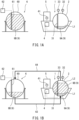
- FIG. 1A to FIG. 3B show a liquefied gas monitoring system 1 according to one embodiment.
- the liquefied gas monitoring system 1 is installed on a ship 5.
- the liquefied gas monitoring system 1 may be installed on a stationary facility, such as a marine facility or an on-land facility, or may be installed on a mobile body that travels on the land or in the air (e.g., a tank truck, a railcar, or an airplane).
- FIG. 1A and FIG. 1B are drawings for describing loading for the first time, i.e., the first loading, onto the ship 5.
- FIG. 1A shows a state before the loading
- FIG. 1B shows a state after the loading.
- the liquefied gas monitoring system 1 includes a container 2, which contains liquefied gas 9, which is obtained by liquefaction of single-component gas.
- the single-component gas include hydrogen, ammonia, and methane.
- the liquefied gas 9 may include almost no impurity, or may include impurities to some extent (e.g., 10% by mass or less).
- the container 2 contains liquefied gas 9A with an environmental value Xa. That is, before the first loading, the liquefied gas 9A is fed into the container 2. A gaseous layer over the liquid level of the liquefied gas 9A in the container 2 is filled with a vaporization gas that results from vaporization of the liquefied gas 9A.
- the liquefied gas monitoring system 1 further includes: a liquid level sensor 31, which detects a liquid level height in the container 2; and control circuitry 4 electrically connected to the liquid level sensor 31.
- the liquid level sensor 31 may be any type of sensor, such as a float type sensor, differential pressure type sensor, ultrasonic wave type sensor, or a laser type sensor.
- control circuitry 4 is electrically connected to both a pressure sensor 32 and a temperature sensor 33.
- the pressure sensor 32 detects the pressure of the gaseous layer in the container 2.
- the temperature sensor 33 detects the temperature of the gaseous layer in the container 2.
- the temperature sensor 33 may detect the temperature of the liquefied gas 9 in the container 2.
- the control circuitry 4 is electrically connected also to a display 41. Each time the liquefied gas 9 is fed into the container 2, the control circuitry 4 receives an input of the environmental value X of the liquefied gas 9. As mentioned above, the liquefied gas 9A is fed into the container 2 before the first loading. Accordingly, the environmental value Xa of the liquefied gas 9A is inputted to the control circuitry 4 before the first loading.
- control circuitry 4 (as with control circuitry 62, 72, and 82, which will be described below), the functionality of the elements disclosed herein may be implemented using circuitry or processing circuitry which includes general purpose processors, special purpose processors, integrated circuits, ASICs ("Application Specific Integrated Circuits"), conventional circuitry and/or combinations thereof which are configured or programmed to perform the disclosed functionality.
- Processors are considered processing circuitry or circuitry as they include transistors and other circuitry therein.
- the circuitry, units, or means are hardware that carry out or are programmed to perform the recited functionality.
- the hardware may be any hardware disclosed herein or otherwise known which is programmed or configured to carry out the recited functionality.
- the hardware is a processor which may be considered a type of circuitry
- the circuitry, means, or units are a combination of hardware and software, the software being used to configure the hardware and/or processor.
- the first loading onto the ship 5 is performed between the ship 5 and an on-land facility 6.
- the on-land facility 6 includes: a container 60, which contains the liquefied gas 9; a liquid level sensor 61, which detects a liquid level height in the container 60; and control circuitry 62 electrically connected to the liquid level sensor 61.
- the loading onto the ship 5 may be performed between the ship 5 and a marine facility. Further alternatively, the loading onto the ship 5 may be performed between the ship 5 and another ship.
- the container 60 contains liquefied gas 9B with an environmental value Xb.
- the environmental value Xb of the liquefied gas 9B may be the same as, or different from, the environmental value Xa of the liquefied gas 9A.
- a gaseous layer over the liquid level of the liquefied gas 9B in the container 60 is filled with a vaporization gas that results from vaporization of the liquefied gas 9B.
- the container 2 of the ship 5 and the container 60 of the on-land facility 6 are connected by a liquid pipe passage 63 and a gas pipe passage 64 as shown in FIG. 1B .
- One end portion of the liquid pipe passage 63 is a fixed pipe mounted on the ship 5, and the other end portion of the liquid pipe passage 63 is a fixed pipe mounted on the on-land facility 6.
- a loading arm installed at the quay wall serves as the middle portion of the liquid pipe passage 63.
- FIG. 1A the illustration of the liquid pipe passage 63 is omitted for the purpose of simplifying the drawing.
- one end portion of the gas pipe passage 64 is a fixed pipe mounted on the ship 5, and the other end portion of the gas pipe passage 64 is a fixed pipe mounted on the on-land facility 6.
- a loading arm installed at the quay wall serves as the middle portion of the gas pipe passage 64.
- FIG. 1A the illustration of the gas pipe passage 64 is omitted for the purpose of simplifying the drawing.
- the liquid pipe passage 63 is drawn under the containers 2 and 60, and the gas pipe passage 64 is drawn over the containers 2 and 60.
- an actual route and actual positions of openings of each of the liquid pipe passage 63 and the gas pipe passage 64 are set appropriately.
- the liquefied gas 9B is fed from the container 60 of the on-land facility 6 to the container 2 of the ship 5 through the liquid pipe passage 63, and the vaporization gas is fed from the gaseous layer in the container 2 to the gaseous layer in the container 60 through the gas pipe passage 64.
- the control circuitry 4 determines an amount Ya of the liquefied gas 9A previously fed into and still remaining in the container 2 based on a liquid level height L1 detected by the liquid level sensor 31, a pressure P detected by the pressure sensor 32, and a temperature T detected by the temperature sensor 33, and stores the determined amount Ya of the liquefied gas 9A together with the environmental value Xa.
- the amount Ya is in units of, for example, kg (the same applies to an amount Yb and so forth described below). At the first loading, only the previously fed liquefied gas 9A remains in the container 2.
- control circuitry 4 calculates the amount Ya of the liquefied gas 9A by multiplying the internal volume of the container 2 under the liquid level height L1 detected by the liquid level sensor 31 by the density of the liquefied gas 9 at the pressure P and the temperature T.
- the density of the liquefied gas 9A is the same as the density of the liquefied gas 9.
- the density of the liquefied gas 9 at the saturated temperature (-253°C) when the pressure is the atmospheric pressure (about 0.1 MPa) is 71 kg/m3.
- the pressure changes to 1.0 MPa (saturated temperature: -242°C) the density decreases to 50 kg/m3.
- the control circuitry 4 prestores a physical property table, or a relational expression, that indicates a relationship among the pressure, the temperature, and the density of the liquefied gas 9.
- the control circuitry 4 determines the density of the liquefied gas 9 by using the physical property table or the relational expression.
- the environmental value Xb of the liquefied gas 9B fed into the container 2 is inputted to the control circuitry 4.
- the inputting of the environmental value Xb to the control circuitry 4 may be performed by wireless communication from the control circuitry 62 to the control circuitry 4 in a case where the environmental value Xb of the liquefied gas 9B is prestored in the control circuitry 62, or may be manually performed by a worker via an inputter electrically connected to the control circuitry 4.
- the control circuitry 4 determines an amount Yb of the liquefied gas 9B fed at this time based on a liquid level height L2 measured by the liquid level sensor 31, the pressure P detected by the pressure sensor 32, and the temperature T detected by the temperature sensor 33, and stores the determined amount Yb of the liquefied gas 9B together with the environmental value Xb. Specifically, the control circuitry 4 calculates the amount Yb of the liquefied gas 9B by multiplying the internal volume of the container 2 between the liquid level height L1 before the loading and the liquid level height L2 after the loading by the density of the liquefied gas 9 at the pressure P and the temperature T.
- the previously fed liquefied gas 9A is the only liquefied gas 9 remaining in the container 2. Therefore, if the amount Ya and the environmental value Xa of the previously fed liquefied gas 9A, and the amount Yb and the environmental value Xb of the liquefied gas 9B fed at this time, are stored, then by referring to these data, the amounts Ya and Yb and the environmental values Xa and Xb of the liquefied gas 9A and 9B, which are mixed together, can be precisely recognized.
- the control circuitry 4 causes the display 41 to concurrently display the amount Ya and the environmental value Xa of the previously fed liquefied gas 9A and the amount Yb and the environmental value Xb of the liquefied gas 9B fed at this time. This makes it possible to visually recognize the amounts Ya and Yb and the environmental values Xa and Xb of the liquefied gas 9A and 9B, which are mixed together.
- FIG. 2A and FIG. 2B are drawings for describing unloading from the ship 5.
- FIG. 2A shows a state before the unloading
- FIG. 2B shows a state after the unloading.
- the on-land facility 7 includes: a container 70, which contains the liquefied gas 9; a liquid level sensor 71, which detects a liquid level height in the container 70; and control circuitry 72 electrically connected to the liquid level sensor 71.
- the unloading from the ship 5 may be performed between the ship 5 and a marine facility. Further alternatively, the unloading from the ship 5 may be performed between the ship 5 and another ship.
- the container 70 contains liquefied gas 9C with an environmental value Xc.
- the environmental value Xc of the liquefied gas 9C may be the same as the environmental value Xa of the liquefied gas 9A or the environmental value Xb of the liquefied gas 9B, or may be different from both the environmental value Xa of the liquefied gas 9A and the environmental value Xb of the liquefied gas 9B.
- a gaseous layer over the liquid level of the liquefied gas 9C in the container 70 is filled with a vaporization gas that results from vaporization of the liquefied gas 9C.
- the container 2 of the ship 5 and the container 70 of the on-land facility 7 are connected by a liquid pipe passage 73 and a gas pipe passage 74 as shown in FIG. 2B .
- One end portion of the liquid pipe passage 73 is a fixed pipe mounted on the ship 5, and the other end portion of the liquid pipe passage 73 is a fixed pipe mounted on the on-land facility 7.
- a loading arm installed at the quay wall serves as the middle portion of the liquid pipe passage 73.
- FIG. 2A the illustration of the liquid pipe passage 73 is omitted for the purpose of simplifying the drawing.
- one end portion of the gas pipe passage 74 is a fixed pipe mounted on the ship 5, and the other end portion of the gas pipe passage 74 is a fixed pipe mounted on the on-land facility 7.
- a loading arm installed at the quay wall serves as the middle portion of the gas pipe passage 74.
- FIG. 2A the illustration of the gas pipe passage 74 is omitted for the purpose of simplifying the drawing.
- the liquid pipe passage 73 is drawn under the containers 2 and 70, and the gas pipe passage 74 is drawn over the containers 2 and 70.
- an actual route and actual positions of openings of each of the liquid pipe passage 73 and the gas pipe passage 74 are set appropriately.
- the control circuitry 4 determines amounts Ya1 and Yb1 of the liquefied gas 9A and 9B, respectively, which have been fed into the container 2 at the most recent at least two times of liquefied gas feeding into the container 2 and which are present in the container 2, based on a liquid level height L3 detected by the liquid level sensor 31, the pressure P detected by the pressure sensor 32, and the temperature T detected by the temperature sensor 33, and stores the determined amounts Ya1 and Yb1 of the liquefied gas 9A and 9B together with the environmental values Xa and Xb.
- control circuitry 4 calculates a total amount Y of the liquefied gas 9 by multiplying the internal volume of the container 2 under the liquid level height L3 detected by the liquid level sensor 31 by the density of the liquefied gas 9 at the pressure P and the temperature T, and then calculates the amounts Ya1 and Yb1 of the liquefied gas 9A and 9B by multiplying the total amount Y by a ratio (Ya / (Ya + Yb)) and a ratio (Yb / (Ya + Yb)) of the amount Ya and the amount Yb stored after the most recent liquefied gas feeding into the container 2.
- the liquefied gas 9A and 9B which have been fed into the container 2 at the most recent two times of liquefied gas feeding into the container 2, account for a large portion of the liquefied gas 9 present in the container 2 (in the case of the first unloading, account for the entire liquefied gas 9 present in the container 2).
- the amounts Ya1 and Yb1 and the environmental values Xa and Xb of the liquefied gas 9A and 9B, which have been fed into the container 2 at the most recent at least two times of liquefied gas feeding into the container 2 are stored before the reclaiming of the liquefied gas 9, then by comparing these data with data that is stored after the most recent liquefied gas feeding into the container 2, the amount and the environmental value of the liquefied gas 9 that has been consumed as boil off gas before the reclaiming of the liquefied gas 9 can be recognized.
- the control circuitry 4 determines amounts Ya2 and Yb2 of the liquefied gas 9A and 9B, respectively, which have been fed into the container 2 at the most recent at least two times of liquefied gas feeding into the container 2 and which still remain in the container 2, based on a liquid level height L4 detected by the liquid level sensor 31, the pressure P detected by the pressure sensor 32, and the temperature T detected by the temperature sensor 33, and stores the determined amounts Ya2 and Yb2 of the liquefied gas 9A and 9B together with the environmental values Xa and Xb.
- control circuitry 4 calculates the total amount Y of the liquefied gas 9 by multiplying the internal volume of the container 2 under the liquid level height L4 detected by the liquid level sensor 31 by the density of the liquefied gas 9 at the pressure P and the temperature T, and then calculates the amounts Ya2 and Yb2 of the liquefied gas 9A and 9B by multiplying the total amount Y by the ratio (Ya / (Ya + Yb)) and the ratio (Yb / (Ya + Yb)) of the amount Ya and the amount Yb stored after the most recent liquefied gas feeding into the container 2.
- the amounts Ya2 and Yb2 and the environmental values Xa and Xb of the liquefied gas 9A and 9B, which have been fed into the container 2 at the most recent at least two times of liquefied gas feeding into the container 2 are stored. Therefore, by referring to these data, the amounts Ya2 and Yb2 and the environmental values Xa and Xb of the liquefied gas 9A and 9B, which have been fed into the container 2 at the most recent at least two times of liquefied gas feeding into the container 2 and which still remain in the container 2, can be recognized.
- the control circuitry 4 causes the display 41 to concurrently display the amounts Ya2 and Yb2 and the environmental values Xa and Xb of the liquefied gas 9A and 9B, which have been fed into the container 2 at the most recent at least two times of liquefied gas feeding into the container 2 and which still remain in the container 2.
- the control circuitry 4 receives an input of an environmental value Xg of the vaporization gas fed to the gaseous layer in the container 2.
- the inputting of the environmental value Xg to the control circuitry 4 may be performed by wireless communication from the control circuitry 72 to the control circuitry 4 in a case where the environmental value Xg of the vaporization gas is prestored in the control circuitry 72, or may be manually performed by a worker via an inputter electrically connected to the control circuitry 4.
- the gaseous layer in the container 70 of the on-land facility 7 is filled with the vaporization gas that results from the vaporization of the liquefied gas 9C. Accordingly, the environmental value Xg of the vaporization gas fed to the gaseous layer in the container 2 is the same as the environmental value Xc of the liquefied gas 9C.
- the environmental value Xg of the vaporization gas fed from the container 60 into the container 2 may be calculated based on, for example, the mixing ratio of the one liquefied gas and the other liquefied gas.
- the control circuitry 4 After the liquefied gas 9 is reclaimed from the container 2, the control circuitry 4 stores an amount Yg of the vaporization gas that has been fed to the gaseous layer in the container 2 together with the environmental value Xg. This makes it possible to manage not only the amount and the environmental value of the liquefied gas 9, but also the amount and the environmental value of the vaporization gas.
- the amount Yg of the vaporization gas that has been fed to the gaseous layer in the container 2 can be calculated, for example, by integrating the flow rate of the vaporization gas flowing through the gas pipe passage 74.
- the amount Yg of the vaporization gas may be calculated by multiplying the internal volume of the container 2 between the liquid level height L3 before the unloading and the liquid level height L4 after the unloading by the density of the vaporization gas at the pressure P detected by the pressure sensor 32 and the temperature T detected by the temperature sensor 33.
- FIG. 3A and FIG. 3B are drawings for describing loading for the second time, i.e., the second loading, onto the ship 5.
- FIG. 3A shows a state before the loading
- FIG. 3B shows a state after the loading.
- the second loading onto the ship 5 is performed between the ship 5 and an on-land facility 8.
- the on-land facility 8 includes: a container 80, which contains the liquefied gas 9; a liquid level sensor 81, which detects a liquid level height in the container 80; and control circuitry 82 electrically connected to the liquid level sensor 81.
- the on-land facility 8 may be the same as or different from the on-land facility 6, onto which the first loading has been performed.
- the loading onto the ship 5 may be performed between the ship 5 and a marine facility. Further alternatively, the loading onto the ship 5 may be performed between the ship 5 and another ship.
- the container 80 contains liquefied gas 9D with an environmental value Xd.
- the environmental value Xd of the liquefied gas 9D may be the same as the environmental value Xa of the liquefied gas 9A, the environmental value Xb of the liquefied gas 9B, or the environmental value Xc of the liquefied gas 9C, or may be different from all of the environmental value Xa of the liquefied gas 9A, the environmental value Xb of the liquefied gas 9B, and the environmental value Xc of the liquefied gas 9C.
- a gaseous layer over the liquid level of the liquefied gas 9D in the container 80 is filled with a vaporization gas that results from vaporization of the liquefied gas 9D.
- the container 2 of the ship 5 and the container 80 of the on-land facility 8 are connected by a liquid pipe passage 83 and a gas pipe passage 84 as shown in FIG. 3B .
- One end portion of the liquid pipe passage 83 is a fixed pipe mounted on the ship 5, and the other end portion of the liquid pipe passage 83 is a fixed pipe mounted on the on-land facility 8.
- a loading arm installed at the quay wall serves as the middle portion of the liquid pipe passage 83.
- FIG. 1A the illustration of the liquid pipe passage 83 is omitted for the purpose of simplifying the drawing.
- one end portion of the gas pipe passage 84 is a fixed pipe mounted on the ship 5, and the other end portion of the gas pipe passage 84 is a fixed pipe mounted on the on-land facility 8.
- a loading arm installed at the quay wall serves as the middle portion of the gas pipe passage 84.
- FIG. 1A the illustration of the gas pipe passage 84 is omitted for the purpose of simplifying the drawing.
- the liquid pipe passage 83 is drawn under the containers 2 and 80, and the gas pipe passage 84 is drawn over the containers 2 and 80.
- an actual route and actual positions of openings of each of the liquid pipe passage 83 and the gas pipe passage 84 are set appropriately.
- the liquefied gas 9D is fed from the container 80 of the on-land facility 8 to the container 2 of the ship 5 through the liquid pipe passage 83, and the vaporization gas is fed from the gaseous layer in the container 2 to the gaseous layer in the container 80 through the gas pipe passage 84.
- the control circuitry 4 determines an amount Yb3 of the liquefied gas 9B previously fed into and still remaining in the container 2 based on a liquid level height L5 detected by the liquid level sensor 31, the pressure P detected by the pressure sensor 32, and the temperature T detected by the temperature sensor 33, and stores the determined amount Yb3 of the liquefied gas 9B together with the environmental value Xb.
- control circuitry 4 calculates the total amount Y of the liquefied gas 9 by multiplying the internal volume of the container 2 under the liquid level height L5 detected by the liquid level sensor 31 by the density of the liquefied gas 9 at the pressure P and the temperature T, and then calculates the amount Yb3 of the liquefied gas 9B by multiplying the total amount Y by the ratio (Yb / (Ya + Yb)) of the amount Yb stored after the previous liquefied gas feeding.
- the environmental value Xd of the liquefied gas 9D fed into the container 2 is inputted to the control circuitry 4.
- the inputting of the environmental value Xd to the control circuitry 4 may be performed by wireless communication from the control circuitry 82 to the control circuitry 4 in a case where the environmental value Xd of the liquefied gas 9D is prestored in the control circuitry 82, or may be manually performed by a worker via an inputter electrically connected to the control circuitry 4.
- the control circuitry 4 determines an amount Yd of the liquefied gas 9D fed at this time based on a liquid level height L6 measured by the liquid level sensor 31, the pressure P detected by the pressure sensor 32, and the temperature T detected by the temperature sensor 33, and stores the determined amount Yd of the liquefied gas 9D together with the environmental value Xd. Specifically, the control circuitry 4 calculates the amount Yd of the liquefied gas 9D by multiplying the internal volume of the container 2 between the liquid level height L5 before the loading and the liquid level height L6 after the loading by the density of the liquefied gas 9 at the pressure P and the temperature T.
- the liquefied gas 9D Before the liquefied gas 9D is fed into the container 2, a large portion of the liquefied gas 9 remaining in the container 2 is the liquefied gas 9B previously fed into the container 2. Therefore, if the amount Yb3 and the environmental value Xb of the previously fed liquefied gas 9B, and the amount Yd and the environmental value Xd of the liquefied gas 9D fed at this time, are stored, then by referring to these data, the amounts Yb3 and Yd and the environmental values Xb and Xd of the liquefied gas 9B and 9D, which are mixed together, can be precisely recognized. In addition, by referring to the past data, a mixing history of the liquefied gas 9 can be tracked.
- the control circuitry 4 may, based solely on the liquid level height (L1, L2, L5, or L6) detected by the liquid level sensor 31, determine, before the liquefied gas 9 is fed into the container 2, the amount of the liquefied gas (9A or 9B) previously fed into and still remaining in the container 2, and determine, after the liquefied gas is fed into the container 2, the amount of the liquefied gas (9B or 9D) fed at this time.
- the control circuitry 4 may, based solely on the liquid level height (L1, L2, L5, or L6) detected by the liquid level sensor 31, determine, before the liquefied gas 9 is fed into the container 2, the amount of the liquefied gas (9A or 9B) previously fed into and still remaining in the container 2, and determine, after the liquefied gas is fed into the container 2, the amount of the liquefied gas (9B or 9D) fed at this time.
- the control circuitry 4 may, based solely on the liquid level height (L3 or L4) detected by the liquid level sensor 31, determine, before the liquefied gas is reclaimed from the container 2, the amounts of the liquefied gas 9A and 9B, which have been fed into the container 2 at the most recent at least two times of liquefied gas feeding into the container 2 and which are present in the container 2, and determine, after the liquefied gas 9 is reclaimed from the container 2, the amounts of the liquefied gas 9A and 9B, which have been fed into the container 2 at the most recent at least two times of liquefied gas feeding into the container 2 and which still remain in the container 2.
- the amount of the liquefied gas is determined not only based on the liquid level height detected by the liquid level sensor 31, but also based on the pressure P detected by the pressure sensor 32 and the temperature T detected by the temperature sensor 33 as in the above-described embodiment, the amount of the liquefied gas can be determined precisely.
- the present disclosure provides a liquefied gas monitoring system including: a container that contains liquefied gas that is obtained by liquefaction of single-component gas; a liquid level sensor that detects a liquid level height in the container; and control circuitry that receives, each time the liquefied gas is fed into the container, an input of an environmental value of the fed liquefied gas.
- the control circuitry before the liquefied gas is fed into the container, determines an amount of the liquefied gas previously fed into and still remaining in the container based on the liquid level height detected by the liquid level sensor, and stores the determined amount of the previously fed liquefied gas together with the environmental value; and after the liquefied gas is fed into the container, determines an amount of the liquefied gas fed at this time based on the liquid level height detected by the liquid level sensor, and stores the determined amount of the liquefied gas fed at this time together with the environmental value.
- the liquefied gas Before the liquefied gas is fed into the container, a large portion of the liquefied gas remaining in the container is the liquefied gas previously fed into the container. Therefore, if the amount and the environmental value of the previously fed liquefied gas, and the amount and the environmental value of the liquefied gas fed at this time, are stored, then by referring to these data, the amounts and the environmental values of the previously fed liquefied gas and the liquefied gas fed at this time, which are mixed together, can be precisely recognized. In addition, by referring to the past data, a mixing history of the liquefied gas can be tracked.
- the above liquefied gas monitoring system may include: a pressure sensor that detects a pressure of a gaseous layer in the container; and a temperature sensor that detects a temperature of the gaseous layer or a temperature of the liquefied gas in the container.
- the control circuitry may, not only based on the liquid level height detected by the liquid level sensor, but also based on the pressure detected by the pressure sensor and the temperature detected by the temperature sensor, determine, before the liquefied gas is fed into the container, the amount of the liquefied gas previously fed into and still remaining in the container, and determine, after the liquefied gas is fed into the container, the amount of the liquefied gas fed at this time. This configuration makes it possible to precisely determine the amount of the liquefied gas.
- control circuitry may cause a display to concurrently display the amount and the environmental value of the previously fed liquefied gas and the amount and the environmental value of the liquefied gas fed at this time.
- This configuration makes it possible to visually recognize the amounts and the environmental values of one liquefied gas and the other liquefied gas that are mixed together.
- the control circuitry may: before the liquefied gas is reclaimed from the container, determine, based on the liquid level height detected by the liquid level sensor, amounts of the liquefied gas that have been fed into the container at most recent at least two times of liquefied gas feeding into the container and that are present in the container, and store each of the determined amounts of the liquefied gas together with the environmental value; and after the liquefied gas is reclaimed from the container, determine, based on the liquid level height detected by the liquid level sensor, amounts of the liquefied gas that have been fed into the container at the most recent at least two times of liquefied gas feeding into the container and that still remain in the container, and store each of the determined amounts of the liquefied gas together with the environmental value.
- the liquefied gas fed into the container at the most recent two times of liquefied gas feeding into the container accounts for a large portion of the liquefied gas present in the container. Therefore, if the amounts and the environmental values of the liquefied gas fed into the container at the most recent at least two times of liquefied gas feeding into the container are stored before the reclaiming of the liquefied gas, then by comparing these data with data that is stored after the most recent liquefied gas feeding into the container, the amount and the environmental value of the liquefied gas that has been consumed as boil off gas before the reclaiming of the liquefied gas can be recognized.
- the amounts and the environmental values of the liquefied gas fed into the container at the most recent at least two times of liquefied gas feeding into the container are stored. Therefore, by referring to these data, the amounts and the environmental values of the liquefied gas fed into the container at the most recent at least two times of liquefied gas feeding into the container and still remaining in the container can be recognized.
- the liquefied gas monitoring system may include: a pressure sensor that detects a pressure of a gaseous layer in the container; and a temperature sensor that detects a temperature of the gaseous layer or a temperature of the liquefied gas in the container.
- the control circuitry may, not only based on the liquid level height detected by the liquid level sensor, but also based on the pressure detected by the pressure sensor and the temperature detected by the temperature sensor, determine, before the liquefied gas is reclaimed from the container, the amounts of the liquefied gas that have been fed into the container at the most recent at least two times of liquefied gas feeding into the container and that are present in the container, and determine, after the liquefied gas is reclaimed from the container, the amounts of the liquefied gas that have been fed into the container at the most recent at least two times of liquefied gas feeding into the container and that still remain in the container.
- This configuration makes it possible to precisely determine the amounts of the liquefied gas.
- control circuitry may cause a display to concurrently display the amounts and the environmental values of the liquefied gas fed into the container at the most recent at least two times of liquefied gas feeding into the container and still remaining in the container.
- This configuration makes it possible to visually recognize the amounts and the environmental values of the liquefied gas fed into the container at the most recent at least two times of liquefied gas feeding into the container and still remaining in the container.
- a vaporization gas may be fed to a gaseous layer in the container, and the control circuitry may receive an input of an environmental value of the vaporization gas, and after the liquefied gas is reclaimed from the container, the control circuitry may store an amount of the vaporization gas that has been fed to the gaseous layer in the container together with the environmental value.
Landscapes
- Engineering & Computer Science (AREA)
- Business, Economics & Management (AREA)
- Physics & Mathematics (AREA)
- Mechanical Engineering (AREA)
- General Engineering & Computer Science (AREA)
- General Physics & Mathematics (AREA)
- Economics (AREA)
- Health & Medical Sciences (AREA)
- Tourism & Hospitality (AREA)
- Strategic Management (AREA)
- Marketing (AREA)
- Theoretical Computer Science (AREA)
- General Business, Economics & Management (AREA)
- Primary Health Care (AREA)
- Human Resources & Organizations (AREA)
- General Health & Medical Sciences (AREA)
- Public Health (AREA)
- Water Supply & Treatment (AREA)
- Thermal Sciences (AREA)
- Entrepreneurship & Innovation (AREA)
- Accounting & Taxation (AREA)
- Development Economics (AREA)
- Finance (AREA)
- Filling Or Discharging Of Gas Storage Vessels (AREA)
- Management, Administration, Business Operations System, And Electronic Commerce (AREA)
Abstract
Description
- The present disclosure relates to a liquefied gas monitoring system.
- Conventionally, liquefied gases obtained by liquefaction of single-component gases have been traded. Examples of such single-component gas include hydrogen, ammonia, and methane. In a general gas liquefaction method, the gas is cooled and condensed. Alternatively, there is a method that uses, as liquefied gas, an organic hydride (e.g., methylcyclohexane) in which reversibly releasable hydrogen is chemically combined with benzene or naphthalene, because the organic hydride is in a liquid form at normal temperature and pressure. That is, in the case of using the organic hydride, hydrogen is liquefied by chemically combining the hydrogen with a carrier.
- PTL 1:
Japanese Laid-Open Patent Application Publication No. 2020-86503 - There is a case where in the process of commodity circulation of liquefied gas, the liquefied gas gets mixed with the same kind of liquefied gas in a container. In this case, however, even though one liquefied gas and the other liquefied gas that are mixed together are the same kind of liquefied gas, the environmental value of each liquefied gas varies depending on, for example, its production method. Accordingly, when the one liquefied gas and the other liquefied gas with different environmental values from each other are mixed together in the container, the environmental value of the mixed liquefied gas in the container will be different from these environmental values. In electric power trading, not only is the electric power itself traded, but the environmental value thereof is also traded. It is considered that this will be the case also in the future liquefied gas trading. For this reason, in a case where one liquefied gas and the other liquefied gas with different environmental values from each other are mixed together in the process of their commodity circulation, it is necessary to calculate the environmental value of the mixed liquefied gas to ensure the reliability of the trading.
- The "environmental value of the liquefied gas" herein means an economic value thereof that indicates the level of contribution to environmental load reduction in the production of the single-component gas. For example, the environmental value is high in a case where the amount of carbon dioxide emission in the production of the single-component gas is small. In a case where single-component gas is produced by chemical bonding of different components to each other (e.g., in a case where ammonia is produced by chemical bonding of hydrogen and nitrogen to each other), the amount of carbon dioxide emission in the production of each of these different components is also reflected in the environmental value of the single-component gas.
- In order to properly calculate the environmental value of the aforementioned mixed liquefied gas, it is necessary to precisely recognize the amounts of the one liquefied gas and the other liquefied gas that are mixed together and their respective environmental values.
Patent Literature 1 describes a hydrogen gas supply system for supplying hydrogen gas to a user as a fuel.Patent Literature 1 describes that one hydrogen gas and the other hydrogen gas with different environmental values from each other are mixed together in a hydrogen gas container, and the environmental value of each hydrogen gas and the environmental value of the mixed hydrogen gas are separately displayed on a display. However, a problem to be solved by the technique ofPatent Literature 1 has nothing to do with the above-described mixing of liquefied gas. - In view of the above, an object of the present disclosure is to provide a liquefied gas monitoring system that makes it possible to precisely recognize the amounts of one liquefied gas and the other liquefied gas that are mixed together and their respective environmental values.
- The present disclosure provides a liquefied gas monitoring system including: a container that contains liquefied gas that is obtained by liquefaction of single-component gas; a liquid level sensor that detects a liquid level height in the container; and control circuitry that receives, each time the liquefied gas is fed into the container, an input of an environmental value of the fed liquefied gas. The control circuitry: before the liquefied gas is fed into the container, determines an amount of the liquefied gas previously fed into and still remaining in the container based on the liquid level height detected by the liquid level sensor, and stores the determined amount of the previously fed liquefied gas together with the environmental value; and after the liquefied gas is fed into the container, determines an amount of the liquefied gas fed at this time based on the liquid level height detected by the liquid level sensor, and stores the determined amount of the liquefied gas fed at this time together with the environmental value.
- The present disclosure makes it possible to precisely recognize the amounts of one liquefied gas and the other liquefied gas that are mixed together and their respective environmental values.
-
-
FIG. 1A shows a state before the first loading onto a ship on which a liquefied gas monitoring system according to one embodiment is installed. -
FIG. 1B shows a state after the first loading onto the ship. -
FIG. 2A shows a state before unloading from the ship. -
FIG. 2B shows a state after the unloading from the ship. -
FIG. 3A shows a state before the second loading onto the ship. -
FIG. 3B shows a state after the second loading onto the ship. -
FIG. 1A to FIG. 3B show a liquefiedgas monitoring system 1 according to one embodiment. In the present embodiment, the liquefiedgas monitoring system 1 is installed on aship 5. Alternatively, the liquefiedgas monitoring system 1 may be installed on a stationary facility, such as a marine facility or an on-land facility, or may be installed on a mobile body that travels on the land or in the air (e.g., a tank truck, a railcar, or an airplane). -
FIG. 1A and FIG. 1B are drawings for describing loading for the first time, i.e., the first loading, onto theship 5.FIG. 1A shows a state before the loading, andFIG. 1B shows a state after the loading. - The liquefied
gas monitoring system 1 includes acontainer 2, which containsliquefied gas 9, which is obtained by liquefaction of single-component gas. Examples of the single-component gas include hydrogen, ammonia, and methane. The liquefiedgas 9 may include almost no impurity, or may include impurities to some extent (e.g., 10% by mass or less). - In the present embodiment, before the first loading, the
container 2 contains liquefiedgas 9A with an environmental value Xa. That is, before the first loading, theliquefied gas 9A is fed into thecontainer 2. A gaseous layer over the liquid level of the liquefiedgas 9A in thecontainer 2 is filled with a vaporization gas that results from vaporization of the liquefiedgas 9A. - The liquefied
gas monitoring system 1 further includes: aliquid level sensor 31, which detects a liquid level height in thecontainer 2; andcontrol circuitry 4 electrically connected to theliquid level sensor 31. Theliquid level sensor 31 may be any type of sensor, such as a float type sensor, differential pressure type sensor, ultrasonic wave type sensor, or a laser type sensor. - In the present embodiment, the
control circuitry 4 is electrically connected to both apressure sensor 32 and atemperature sensor 33. However, the illustration of their connection lines is omitted in all the drawings for the purpose of simplifying the drawings. Thepressure sensor 32 detects the pressure of the gaseous layer in thecontainer 2. Thetemperature sensor 33 detects the temperature of the gaseous layer in thecontainer 2. Alternatively, thetemperature sensor 33 may detect the temperature of the liquefiedgas 9 in thecontainer 2. - The
control circuitry 4 is electrically connected also to adisplay 41. Each time the liquefiedgas 9 is fed into thecontainer 2, thecontrol circuitry 4 receives an input of the environmental value X of the liquefiedgas 9. As mentioned above, the liquefiedgas 9A is fed into thecontainer 2 before the first loading. Accordingly, the environmental value Xa of the liquefiedgas 9A is inputted to thecontrol circuitry 4 before the first loading. - Regarding the control circuitry 4 (as with
control circuitry - In the present embodiment, the first loading onto the
ship 5 is performed between theship 5 and an on-land facility 6. The on-land facility 6 includes: acontainer 60, which contains the liquefiedgas 9; aliquid level sensor 61, which detects a liquid level height in thecontainer 60; andcontrol circuitry 62 electrically connected to theliquid level sensor 61. - Alternatively, the loading onto the
ship 5 may be performed between theship 5 and a marine facility. Further alternatively, the loading onto theship 5 may be performed between theship 5 and another ship. - In the present embodiment, the
container 60 contains liquefiedgas 9B with an environmental value Xb. The environmental value Xb of the liquefiedgas 9B may be the same as, or different from, the environmental value Xa of the liquefiedgas 9A. A gaseous layer over the liquid level of the liquefiedgas 9B in thecontainer 60 is filled with a vaporization gas that results from vaporization of the liquefiedgas 9B. - At the first loading onto the
ship 5, after theship 5 is moored to a quay wall near the on-land facility 6 as shown inFIG. 1A , thecontainer 2 of theship 5 and thecontainer 60 of the on-land facility 6 are connected by aliquid pipe passage 63 and agas pipe passage 64 as shown inFIG. 1B . - One end portion of the
liquid pipe passage 63 is a fixed pipe mounted on theship 5, and the other end portion of theliquid pipe passage 63 is a fixed pipe mounted on the on-land facility 6. A loading arm installed at the quay wall serves as the middle portion of theliquid pipe passage 63. InFIG. 1A , the illustration of theliquid pipe passage 63 is omitted for the purpose of simplifying the drawing. - Similarly, one end portion of the
gas pipe passage 64 is a fixed pipe mounted on theship 5, and the other end portion of thegas pipe passage 64 is a fixed pipe mounted on the on-land facility 6. A loading arm installed at the quay wall serves as the middle portion of thegas pipe passage 64. InFIG. 1A , the illustration of thegas pipe passage 64 is omitted for the purpose of simplifying the drawing. - In
FIG. 1B , for the purpose of simplifying the drawing, theliquid pipe passage 63 is drawn under thecontainers gas pipe passage 64 is drawn over thecontainers liquid pipe passage 63 and thegas pipe passage 64 are set appropriately. For example, there may be a dome at the top of thecontainer 2 of theship 5, and the one end portion of each of theliquid pipe passage 63 and thegas pipe passage 64 may penetrate the dome. - After the connection by the
liquid pipe passage 63 and thegas pipe passage 64 is completed, the liquefiedgas 9B is fed from thecontainer 60 of the on-land facility 6 to thecontainer 2 of theship 5 through theliquid pipe passage 63, and the vaporization gas is fed from the gaseous layer in thecontainer 2 to the gaseous layer in thecontainer 60 through thegas pipe passage 64. - Before the liquefied
gas 9B is fed into thecontainer 2, thecontrol circuitry 4 determines an amount Ya of the liquefiedgas 9A previously fed into and still remaining in thecontainer 2 based on a liquid level height L1 detected by theliquid level sensor 31, a pressure P detected by thepressure sensor 32, and a temperature T detected by thetemperature sensor 33, and stores the determined amount Ya of the liquefiedgas 9A together with the environmental value Xa. The amount Ya is in units of, for example, kg (the same applies to an amount Yb and so forth described below). At the first loading, only the previously fed liquefiedgas 9A remains in thecontainer 2. Accordingly, thecontrol circuitry 4 calculates the amount Ya of the liquefiedgas 9A by multiplying the internal volume of thecontainer 2 under the liquid level height L1 detected by theliquid level sensor 31 by the density of the liquefiedgas 9 at the pressure P and the temperature T. - Since the liquefied
gas 9A is the liquefiedgas 9 merely distinguished by its environmental value X, the density of the liquefiedgas 9A is the same as the density of the liquefiedgas 9. The same applies to the liquefiedgas 9B as well as to liquefiedgas 9C and liquefiedgas 9D, which will be described below. - For example, in a case where the liquefied
gas 9 is liquefied hydrogen, the density of the liquefiedgas 9 at the saturated temperature (-253°C) when the pressure is the atmospheric pressure (about 0.1 MPa) is 71 kg/m3. When the pressure changes to 1.0 MPa (saturated temperature: -242°C), the density decreases to 50 kg/m3. Thecontrol circuitry 4 prestores a physical property table, or a relational expression, that indicates a relationship among the pressure, the temperature, and the density of the liquefiedgas 9. Thecontrol circuitry 4 determines the density of the liquefiedgas 9 by using the physical property table or the relational expression. - Before, during, or after the loading, the environmental value Xb of the liquefied
gas 9B fed into thecontainer 2 is inputted to thecontrol circuitry 4. The inputting of the environmental value Xb to thecontrol circuitry 4 may be performed by wireless communication from thecontrol circuitry 62 to thecontrol circuitry 4 in a case where the environmental value Xb of the liquefiedgas 9B is prestored in thecontrol circuitry 62, or may be manually performed by a worker via an inputter electrically connected to thecontrol circuitry 4. - After the liquefied
gas 9B is fed into thecontainer 2, thecontrol circuitry 4 determines an amount Yb of the liquefiedgas 9B fed at this time based on a liquid level height L2 measured by theliquid level sensor 31, the pressure P detected by thepressure sensor 32, and the temperature T detected by thetemperature sensor 33, and stores the determined amount Yb of the liquefiedgas 9B together with the environmental value Xb. Specifically, thecontrol circuitry 4 calculates the amount Yb of the liquefiedgas 9B by multiplying the internal volume of thecontainer 2 between the liquid level height L1 before the loading and the liquid level height L2 after the loading by the density of the liquefiedgas 9 at the pressure P and the temperature T. - Before the liquefied
gas 9B is fed into thecontainer 2, the previously fed liquefiedgas 9A is the onlyliquefied gas 9 remaining in thecontainer 2. Therefore, if the amount Ya and the environmental value Xa of the previously fed liquefiedgas 9A, and the amount Yb and the environmental value Xb of the liquefiedgas 9B fed at this time, are stored, then by referring to these data, the amounts Ya and Yb and the environmental values Xa and Xb of the liquefiedgas - After the liquefied
gas 9B is fed into thecontainer 2, thecontrol circuitry 4 causes thedisplay 41 to concurrently display the amount Ya and the environmental value Xa of the previously fed liquefiedgas 9A and the amount Yb and the environmental value Xb of the liquefiedgas 9B fed at this time. This makes it possible to visually recognize the amounts Ya and Yb and the environmental values Xa and Xb of the liquefiedgas -
FIG. 2A and FIG. 2B are drawings for describing unloading from theship 5.FIG. 2A shows a state before the unloading, andFIG. 2B shows a state after the unloading. - In the present embodiment, unloading from the
ship 5 is performed between theship 5 and an on-land facility 7. The on-land facility 7 includes: acontainer 70, which contains the liquefiedgas 9; aliquid level sensor 71, which detects a liquid level height in thecontainer 70; andcontrol circuitry 72 electrically connected to theliquid level sensor 71. - Alternatively, the unloading from the
ship 5 may be performed between theship 5 and a marine facility. Further alternatively, the unloading from theship 5 may be performed between theship 5 and another ship. - In the present embodiment, the
container 70 contains liquefiedgas 9C with an environmental value Xc. The environmental value Xc of the liquefiedgas 9C may be the same as the environmental value Xa of the liquefiedgas 9A or the environmental value Xb of the liquefiedgas 9B, or may be different from both the environmental value Xa of the liquefiedgas 9A and the environmental value Xb of the liquefiedgas 9B. A gaseous layer over the liquid level of the liquefiedgas 9C in thecontainer 70 is filled with a vaporization gas that results from vaporization of the liquefiedgas 9C. - In the unloading from the
ship 5, after theship 5 is moored to a quay wall near the on-land facility 7 as shown inFIG. 2A , thecontainer 2 of theship 5 and thecontainer 70 of the on-land facility 7 are connected by aliquid pipe passage 73 and agas pipe passage 74 as shown inFIG. 2B . - One end portion of the
liquid pipe passage 73 is a fixed pipe mounted on theship 5, and the other end portion of theliquid pipe passage 73 is a fixed pipe mounted on the on-land facility 7. A loading arm installed at the quay wall serves as the middle portion of theliquid pipe passage 73. InFIG. 2A , the illustration of theliquid pipe passage 73 is omitted for the purpose of simplifying the drawing. - Similarly, one end portion of the
gas pipe passage 74 is a fixed pipe mounted on theship 5, and the other end portion of thegas pipe passage 74 is a fixed pipe mounted on the on-land facility 7. A loading arm installed at the quay wall serves as the middle portion of thegas pipe passage 74. InFIG. 2A , the illustration of thegas pipe passage 74 is omitted for the purpose of simplifying the drawing. - In
FIG. 2B , for the purpose of simplifying the drawing, theliquid pipe passage 73 is drawn under thecontainers gas pipe passage 74 is drawn over thecontainers liquid pipe passage 63 and thegas pipe passage 64 of the on-land facility 6, an actual route and actual positions of openings of each of theliquid pipe passage 73 and thegas pipe passage 74 are set appropriately. - After the connection by the
liquid pipe passage 73 and thegas pipe passage 74 is completed, the liquefiedgas 9, which is the mixture of the liquefiedgas 9A and the liquefiedgas 9B, is reclaimed from thecontainer 2 of theship 5 to thecontainer 70 of the on-land facility 7 through theliquid pipe passage 73, and the vaporization gas is fed from the gaseous layer in thecontainer 70 to the gaseous layer in thecontainer 2 through thegas pipe passage 74. - Before the liquefied
gas 9 is reclaimed from thecontainer 2, thecontrol circuitry 4 determines amounts Ya1 and Yb1 of the liquefiedgas container 2 at the most recent at least two times of liquefied gas feeding into thecontainer 2 and which are present in thecontainer 2, based on a liquid level height L3 detected by theliquid level sensor 31, the pressure P detected by thepressure sensor 32, and the temperature T detected by thetemperature sensor 33, and stores the determined amounts Ya1 and Yb1 of the liquefiedgas control circuitry 4 calculates a total amount Y of the liquefiedgas 9 by multiplying the internal volume of thecontainer 2 under the liquid level height L3 detected by theliquid level sensor 31 by the density of the liquefiedgas 9 at the pressure P and the temperature T, and then calculates the amounts Ya1 and Yb1 of the liquefiedgas container 2. - Before the liquefied
gas 9 is reclaimed from thecontainer 2, the liquefiedgas container 2 at the most recent two times of liquefied gas feeding into thecontainer 2, account for a large portion of the liquefiedgas 9 present in the container 2 (in the case of the first unloading, account for the entireliquefied gas 9 present in the container 2). Therefore, if the amounts Ya1 and Yb1 and the environmental values Xa and Xb of the liquefiedgas container 2 at the most recent at least two times of liquefied gas feeding into thecontainer 2, are stored before the reclaiming of the liquefiedgas 9, then by comparing these data with data that is stored after the most recent liquefied gas feeding into thecontainer 2, the amount and the environmental value of the liquefiedgas 9 that has been consumed as boil off gas before the reclaiming of the liquefiedgas 9 can be recognized. - After the liquefied
gas 9 is reclaimed from thecontainer 2, thecontrol circuitry 4 determines amounts Ya2 and Yb2 of the liquefiedgas container 2 at the most recent at least two times of liquefied gas feeding into thecontainer 2 and which still remain in thecontainer 2, based on a liquid level height L4 detected by theliquid level sensor 31, the pressure P detected by thepressure sensor 32, and the temperature T detected by thetemperature sensor 33, and stores the determined amounts Ya2 and Yb2 of the liquefiedgas control circuitry 4 calculates the total amount Y of the liquefiedgas 9 by multiplying the internal volume of thecontainer 2 under the liquid level height L4 detected by theliquid level sensor 31 by the density of the liquefiedgas 9 at the pressure P and the temperature T, and then calculates the amounts Ya2 and Yb2 of the liquefiedgas container 2. - Thus, also after the reclaiming of the liquefied
gas 9, the amounts Ya2 and Yb2 and the environmental values Xa and Xb of the liquefiedgas container 2 at the most recent at least two times of liquefied gas feeding into thecontainer 2, are stored. Therefore, by referring to these data, the amounts Ya2 and Yb2 and the environmental values Xa and Xb of the liquefiedgas container 2 at the most recent at least two times of liquefied gas feeding into thecontainer 2 and which still remain in thecontainer 2, can be recognized. - Further, after the liquefied
gas 9B is fed into thecontainer 2, thecontrol circuitry 4 causes thedisplay 41 to concurrently display the amounts Ya2 and Yb2 and the environmental values Xa and Xb of the liquefiedgas container 2 at the most recent at least two times of liquefied gas feeding into thecontainer 2 and which still remain in thecontainer 2. This makes it possible to visually recognize the amounts Ya2 and Yb2 and the environmental values Xa and Xb of the liquefiedgas container 2 at the most recent at least two times of liquefied gas feeding into thecontainer 2 and which still remain in thecontainer 2. - In a case where the liquefied
gas 9 is reclaimed from thecontainer 2, thecontrol circuitry 4 receives an input of an environmental value Xg of the vaporization gas fed to the gaseous layer in thecontainer 2. The inputting of the environmental value Xg to thecontrol circuitry 4 may be performed by wireless communication from thecontrol circuitry 72 to thecontrol circuitry 4 in a case where the environmental value Xg of the vaporization gas is prestored in thecontrol circuitry 72, or may be manually performed by a worker via an inputter electrically connected to thecontrol circuitry 4. - As described above, the gaseous layer in the
container 70 of the on-land facility 7 is filled with the vaporization gas that results from the vaporization of the liquefiedgas 9C. Accordingly, the environmental value Xg of the vaporization gas fed to the gaseous layer in thecontainer 2 is the same as the environmental value Xc of the liquefiedgas 9C. In a case where one liquefiedgas 9 and the otherliquefied gas 9 with different environmental values X from each other are mixed together in thecontainer 60, the environmental value Xg of the vaporization gas fed from thecontainer 60 into thecontainer 2 may be calculated based on, for example, the mixing ratio of the one liquefied gas and the other liquefied gas. - After the liquefied
gas 9 is reclaimed from thecontainer 2, thecontrol circuitry 4 stores an amount Yg of the vaporization gas that has been fed to the gaseous layer in thecontainer 2 together with the environmental value Xg. This makes it possible to manage not only the amount and the environmental value of the liquefiedgas 9, but also the amount and the environmental value of the vaporization gas. - The amount Yg of the vaporization gas that has been fed to the gaseous layer in the
container 2 can be calculated, for example, by integrating the flow rate of the vaporization gas flowing through thegas pipe passage 74. Alternatively, the amount Yg of the vaporization gas may be calculated by multiplying the internal volume of thecontainer 2 between the liquid level height L3 before the unloading and the liquid level height L4 after the unloading by the density of the vaporization gas at the pressure P detected by thepressure sensor 32 and the temperature T detected by thetemperature sensor 33. -
FIG. 3A and FIG. 3B are drawings for describing loading for the second time, i.e., the second loading, onto theship 5.FIG. 3A shows a state before the loading, andFIG. 3B shows a state after the loading. - In the present embodiment, the second loading onto the
ship 5 is performed between theship 5 and an on-land facility 8. The on-land facility 8 includes: acontainer 80, which contains the liquefiedgas 9; aliquid level sensor 81, which detects a liquid level height in thecontainer 80; andcontrol circuitry 82 electrically connected to theliquid level sensor 81. The on-land facility 8 may be the same as or different from the on-land facility 6, onto which the first loading has been performed. - Alternatively, the loading onto the
ship 5 may be performed between theship 5 and a marine facility. Further alternatively, the loading onto theship 5 may be performed between theship 5 and another ship. - In the present embodiment, the
container 80 contains liquefiedgas 9D with an environmental value Xd. The environmental value Xd of the liquefiedgas 9D may be the same as the environmental value Xa of the liquefiedgas 9A, the environmental value Xb of the liquefiedgas 9B, or the environmental value Xc of the liquefiedgas 9C, or may be different from all of the environmental value Xa of the liquefiedgas 9A, the environmental value Xb of the liquefiedgas 9B, and the environmental value Xc of the liquefiedgas 9C. A gaseous layer over the liquid level of the liquefiedgas 9D in thecontainer 80 is filled with a vaporization gas that results from vaporization of the liquefiedgas 9D. - At the second loading onto the
ship 5, after theship 5 is moored at a quay wall near the on-land facility 8 as shown inFIG. 3A , thecontainer 2 of theship 5 and thecontainer 80 of the on-land facility 8 are connected by aliquid pipe passage 83 and agas pipe passage 84 as shown inFIG. 3B . - One end portion of the
liquid pipe passage 83 is a fixed pipe mounted on theship 5, and the other end portion of theliquid pipe passage 83 is a fixed pipe mounted on the on-land facility 8. A loading arm installed at the quay wall serves as the middle portion of theliquid pipe passage 83. InFIG. 1A , the illustration of theliquid pipe passage 83 is omitted for the purpose of simplifying the drawing. - Similarly, one end portion of the
gas pipe passage 84 is a fixed pipe mounted on theship 5, and the other end portion of thegas pipe passage 84 is a fixed pipe mounted on the on-land facility 8. A loading arm installed at the quay wall serves as the middle portion of thegas pipe passage 84. InFIG. 1A , the illustration of thegas pipe passage 84 is omitted for the purpose of simplifying the drawing. - In
FIG. 3B , for the purpose of simplifying the drawing, theliquid pipe passage 83 is drawn under thecontainers gas pipe passage 84 is drawn over thecontainers liquid pipe passage 63 and thegas pipe passage 64 of the on-land facility 6, an actual route and actual positions of openings of each of theliquid pipe passage 83 and thegas pipe passage 84 are set appropriately. - After the connection by the
liquid pipe passage 83 and thegas pipe passage 84 is completed, the liquefiedgas 9D is fed from thecontainer 80 of the on-land facility 8 to thecontainer 2 of theship 5 through theliquid pipe passage 83, and the vaporization gas is fed from the gaseous layer in thecontainer 2 to the gaseous layer in thecontainer 80 through thegas pipe passage 84. - Before the liquefied
gas 9D is fed into thecontainer 2, thecontrol circuitry 4 determines an amount Yb3 of the liquefiedgas 9B previously fed into and still remaining in thecontainer 2 based on a liquid level height L5 detected by theliquid level sensor 31, the pressure P detected by thepressure sensor 32, and the temperature T detected by thetemperature sensor 33, and stores the determined amount Yb3 of the liquefiedgas 9B together with the environmental value Xb. Specifically, thecontrol circuitry 4 calculates the total amount Y of the liquefiedgas 9 by multiplying the internal volume of thecontainer 2 under the liquid level height L5 detected by theliquid level sensor 31 by the density of the liquefiedgas 9 at the pressure P and the temperature T, and then calculates the amount Yb3 of the liquefiedgas 9B by multiplying the total amount Y by the ratio (Yb / (Ya + Yb)) of the amount Yb stored after the previous liquefied gas feeding. - Before, during, or after the loading, the environmental value Xd of the liquefied
gas 9D fed into thecontainer 2 is inputted to thecontrol circuitry 4. The inputting of the environmental value Xd to thecontrol circuitry 4 may be performed by wireless communication from thecontrol circuitry 82 to thecontrol circuitry 4 in a case where the environmental value Xd of the liquefiedgas 9D is prestored in thecontrol circuitry 82, or may be manually performed by a worker via an inputter electrically connected to thecontrol circuitry 4. - After the liquefied
gas 9D is fed into thecontainer 2, thecontrol circuitry 4 determines an amount Yd of the liquefiedgas 9D fed at this time based on a liquid level height L6 measured by theliquid level sensor 31, the pressure P detected by thepressure sensor 32, and the temperature T detected by thetemperature sensor 33, and stores the determined amount Yd of the liquefiedgas 9D together with the environmental value Xd. Specifically, thecontrol circuitry 4 calculates the amount Yd of the liquefiedgas 9D by multiplying the internal volume of thecontainer 2 between the liquid level height L5 before the loading and the liquid level height L6 after the loading by the density of the liquefiedgas 9 at the pressure P and the temperature T. - Before the liquefied
gas 9D is fed into thecontainer 2, a large portion of the liquefiedgas 9 remaining in thecontainer 2 is the liquefiedgas 9B previously fed into thecontainer 2. Therefore, if the amount Yb3 and the environmental value Xb of the previously fed liquefiedgas 9B, and the amount Yd and the environmental value Xd of the liquefiedgas 9D fed at this time, are stored, then by referring to these data, the amounts Yb3 and Yd and the environmental values Xb and Xd of the liquefiedgas gas 9 can be tracked. - The present disclosure is not limited to the above-described embodiment. Various modifications can be made without departing from the scope of the present disclosure.
- For example, in a case where the pressure and temperature of the gaseous layer of the liquefied
gas 9 in thecontainer 2 is maintained substantially constant, at the loading onto theship 5, thecontrol circuitry 4 may, based solely on the liquid level height (L1, L2, L5, or L6) detected by theliquid level sensor 31, determine, before the liquefiedgas 9 is fed into thecontainer 2, the amount of the liquefied gas (9A or 9B) previously fed into and still remaining in thecontainer 2, and determine, after the liquefied gas is fed into thecontainer 2, the amount of the liquefied gas (9B or 9D) fed at this time. In this case, at the unloading from theship 5, thecontrol circuitry 4 may, based solely on the liquid level height (L3 or L4) detected by theliquid level sensor 31, determine, before the liquefied gas is reclaimed from thecontainer 2, the amounts of the liquefiedgas container 2 at the most recent at least two times of liquefied gas feeding into thecontainer 2 and which are present in thecontainer 2, and determine, after the liquefiedgas 9 is reclaimed from thecontainer 2, the amounts of the liquefiedgas container 2 at the most recent at least two times of liquefied gas feeding into thecontainer 2 and which still remain in thecontainer 2. - However, if the amount of the liquefied gas is determined not only based on the liquid level height detected by the
liquid level sensor 31, but also based on the pressure P detected by thepressure sensor 32 and the temperature T detected by thetemperature sensor 33 as in the above-described embodiment, the amount of the liquefied gas can be determined precisely. - The present disclosure provides a liquefied gas monitoring system including: a container that contains liquefied gas that is obtained by liquefaction of single-component gas; a liquid level sensor that detects a liquid level height in the container; and control circuitry that receives, each time the liquefied gas is fed into the container, an input of an environmental value of the fed liquefied gas. The control circuitry: before the liquefied gas is fed into the container, determines an amount of the liquefied gas previously fed into and still remaining in the container based on the liquid level height detected by the liquid level sensor, and stores the determined amount of the previously fed liquefied gas together with the environmental value; and after the liquefied gas is fed into the container, determines an amount of the liquefied gas fed at this time based on the liquid level height detected by the liquid level sensor, and stores the determined amount of the liquefied gas fed at this time together with the environmental value.
- Before the liquefied gas is fed into the container, a large portion of the liquefied gas remaining in the container is the liquefied gas previously fed into the container. Therefore, if the amount and the environmental value of the previously fed liquefied gas, and the amount and the environmental value of the liquefied gas fed at this time, are stored, then by referring to these data, the amounts and the environmental values of the previously fed liquefied gas and the liquefied gas fed at this time, which are mixed together, can be precisely recognized. In addition, by referring to the past data, a mixing history of the liquefied gas can be tracked.
- The above liquefied gas monitoring system may include: a pressure sensor that detects a pressure of a gaseous layer in the container; and a temperature sensor that detects a temperature of the gaseous layer or a temperature of the liquefied gas in the container. The control circuitry may, not only based on the liquid level height detected by the liquid level sensor, but also based on the pressure detected by the pressure sensor and the temperature detected by the temperature sensor, determine, before the liquefied gas is fed into the container, the amount of the liquefied gas previously fed into and still remaining in the container, and determine, after the liquefied gas is fed into the container, the amount of the liquefied gas fed at this time. This configuration makes it possible to precisely determine the amount of the liquefied gas.
- After the liquefied gas is fed into the container, the control circuitry may cause a display to concurrently display the amount and the environmental value of the previously fed liquefied gas and the amount and the environmental value of the liquefied gas fed at this time. This configuration makes it possible to visually recognize the amounts and the environmental values of one liquefied gas and the other liquefied gas that are mixed together.
- The control circuitry may: before the liquefied gas is reclaimed from the container, determine, based on the liquid level height detected by the liquid level sensor, amounts of the liquefied gas that have been fed into the container at most recent at least two times of liquefied gas feeding into the container and that are present in the container, and store each of the determined amounts of the liquefied gas together with the environmental value; and after the liquefied gas is reclaimed from the container, determine, based on the liquid level height detected by the liquid level sensor, amounts of the liquefied gas that have been fed into the container at the most recent at least two times of liquefied gas feeding into the container and that still remain in the container, and store each of the determined amounts of the liquefied gas together with the environmental value. Before the liquefied gas is reclaimed from the container, the liquefied gas fed into the container at the most recent two times of liquefied gas feeding into the container accounts for a large portion of the liquefied gas present in the container. Therefore, if the amounts and the environmental values of the liquefied gas fed into the container at the most recent at least two times of liquefied gas feeding into the container are stored before the reclaiming of the liquefied gas, then by comparing these data with data that is stored after the most recent liquefied gas feeding into the container, the amount and the environmental value of the liquefied gas that has been consumed as boil off gas before the reclaiming of the liquefied gas can be recognized. In addition, also after the reclaiming of the liquefied gas, the amounts and the environmental values of the liquefied gas fed into the container at the most recent at least two times of liquefied gas feeding into the container are stored. Therefore, by referring to these data, the amounts and the environmental values of the liquefied gas fed into the container at the most recent at least two times of liquefied gas feeding into the container and still remaining in the container can be recognized.
- The liquefied gas monitoring system may include: a pressure sensor that detects a pressure of a gaseous layer in the container; and a temperature sensor that detects a temperature of the gaseous layer or a temperature of the liquefied gas in the container. The control circuitry may, not only based on the liquid level height detected by the liquid level sensor, but also based on the pressure detected by the pressure sensor and the temperature detected by the temperature sensor, determine, before the liquefied gas is reclaimed from the container, the amounts of the liquefied gas that have been fed into the container at the most recent at least two times of liquefied gas feeding into the container and that are present in the container, and determine, after the liquefied gas is reclaimed from the container, the amounts of the liquefied gas that have been fed into the container at the most recent at least two times of liquefied gas feeding into the container and that still remain in the container. This configuration makes it possible to precisely determine the amounts of the liquefied gas.
- After the liquefied gas is reclaimed from the container, the control circuitry may cause a display to concurrently display the amounts and the environmental values of the liquefied gas fed into the container at the most recent at least two times of liquefied gas feeding into the container and still remaining in the container. This configuration makes it possible to visually recognize the amounts and the environmental values of the liquefied gas fed into the container at the most recent at least two times of liquefied gas feeding into the container and still remaining in the container.
- In a case where the liquefied gas is reclaimed from the container, a vaporization gas may be fed to a gaseous layer in the container, and the control circuitry may receive an input of an environmental value of the vaporization gas, and after the liquefied gas is reclaimed from the container, the control circuitry may store an amount of the vaporization gas that has been fed to the gaseous layer in the container together with the environmental value. This configuration makes it possible to manage not only the amount and the environmental value of the liquefied gas, but also the amount and the environmental value of the vaporization gas.
Claims (7)
- A liquefied gas monitoring system comprising:a container that contains liquefied gas that is obtained by liquefaction of single-component gas;a liquid level sensor that detects a liquid level height in the container; andcontrol circuitry that receives, each time the liquefied gas is fed into the container, an input of an environmental value of the fed liquefied gas, whereinthe control circuitry:before the liquefied gas is fed into the container, determines an amount of the liquefied gas previously fed into and still remaining in the container based on the liquid level height detected by the liquid level sensor, and stores the determined amount of the previously fed liquefied gas together with the environmental value; andafter the liquefied gas is fed into the container, determines an amount of the liquefied gas fed at this time based on the liquid level height detected by the liquid level sensor, and stores the determined amount of the liquefied gas fed at this time together with the environmental value.
- The liquefied gas monitoring system according to claim 1, comprising:a pressure sensor that detects a pressure of a gaseous layer in the container; anda temperature sensor that detects a temperature of the gaseous layer or a temperature of the liquefied gas in the container, whereinthe control circuitry, not only based on the liquid level height detected by the liquid level sensor, but also based on the pressure detected by the pressure sensor and the temperature detected by the temperature sensor, determines, before the liquefied gas is fed into the container, the amount of the liquefied gas previously fed into and still remaining in the container, and determines, after the liquefied gas is fed into the container, the amount of the liquefied gas fed at this time.
- The liquefied gas monitoring system according to claim 1 or 2, wherein
after the liquefied gas is fed into the container, the control circuitry causes a display to concurrently display the amount and the environmental value of the previously fed liquefied gas and the amount and the environmental value of the liquefied gas fed at this time. - The liquefied gas monitoring system according to any one of claims 1 to 3, wherein
the control circuitry:before the liquefied gas is reclaimed from the container, determines, based on the liquid level height detected by the liquid level sensor, amounts of the liquefied gas that have been fed into the container at most recent at least two times of liquefied gas feeding into the container and that are present in the container, and stores each of the determined amounts of the liquefied gas together with the environmental value; andafter the liquefied gas is reclaimed from the container, determines, based on the liquid level height detected by the liquid level sensor, amounts of the liquefied gas that have been fed into the container at the most recent at least two times of liquefied gas feeding into the container and that still remain in the container, and stores each of the determined amounts of the liquefied gas together with the environmental value. - The liquefied gas monitoring system according to claim 4, comprising:a pressure sensor that detects a pressure of a gaseous layer in the container; anda temperature sensor that detects a temperature of the gaseous layer or a temperature of the liquefied gas in the container, whereinthe control circuitry, not only based on the liquid level height detected by the liquid level sensor, but also based on the pressure detected by the pressure sensor and the temperature detected by the temperature sensor, determines, before the liquefied gas is reclaimed from the container, the amounts of the liquefied gas that have been fed into the container at the most recent at least two times of liquefied gas feeding into the container and that are present in the container, and determines, after the liquefied gas is reclaimed from the container, the amounts of the liquefied gas that have been fed into the container at the most recent at least two times of liquefied gas feeding into the container and that still remain in the container.
- The liquefied gas monitoring system according to claim 4 or 5, wherein
after the liquefied gas is reclaimed from the container, the control circuitry causes a display to concurrently display the amounts and the environmental values of the liquefied gas fed into the container at the most recent at least two times of liquefied gas feeding into the container and still remaining in the container. - The liquefied gas monitoring system according to any one of claims 1 to 6, whereinin a case where the liquefied gas is reclaimed from the container, a vaporization gas is fed to a gaseous layer in the container, and the control circuitry receives an input of an environmental value of the vaporization gas, andafter the liquefied gas is reclaimed from the container, the control circuitry stores an amount of the vaporization gas that has been fed to the gaseous layer in the container together with the environmental value.
Applications Claiming Priority (2)
| Application Number | Priority Date | Filing Date | Title |
|---|---|---|---|
| JP2021157355A JP7755962B2 (en) | 2021-09-28 | 2021-09-28 | Liquefied Gas Monitoring System |
| PCT/JP2022/035601 WO2023054232A1 (en) | 2021-09-28 | 2022-09-26 | Liquefied gas monitoring system |
Publications (2)
| Publication Number | Publication Date |
|---|---|
| EP4411624A1 true EP4411624A1 (en) | 2024-08-07 |
| EP4411624A4 EP4411624A4 (en) | 2025-10-29 |
Family
ID=85780198
Family Applications (1)
| Application Number | Title | Priority Date | Filing Date |
|---|---|---|---|
| EP22876099.7A Pending EP4411624A4 (en) | 2021-09-28 | 2022-09-26 | LIQUEFIED GAS MONITORING SYSTEM |
Country Status (7)
| Country | Link |
|---|---|
| US (1) | US12687259B2 (en) |
| EP (1) | EP4411624A4 (en) |
| JP (1) | JP7755962B2 (en) |
| KR (1) | KR20240052037A (en) |
| CN (1) | CN117980941A (en) |
| AU (1) | AU2022353474A1 (en) |
| WO (1) | WO2023054232A1 (en) |
Families Citing this family (1)
| Publication number | Priority date | Publication date | Assignee | Title |
|---|---|---|---|---|
| WO2026089043A1 (en) * | 2024-10-25 | 2026-04-30 | ソフトバンクグループ株式会社 | Storage center |
Family Cites Families (9)
| Publication number | Priority date | Publication date | Assignee | Title |
|---|---|---|---|---|
| US6662649B1 (en) * | 1999-03-19 | 2003-12-16 | Simmons Sirvey Corporation | Material level monitoring and reporting |
| JP2002297697A (en) | 2001-03-28 | 2002-10-11 | Toshiba Corp | Environmental impact assessment methods and programs for products |
| JP2003130296A (en) | 2001-10-29 | 2003-05-08 | Osaka Gas Co Ltd | LNG management system and its charging system |
| JP4918783B2 (en) | 2006-01-06 | 2012-04-18 | 中国電力株式会社 | LNG receipt / payment quantity management apparatus and receipt / payment quantity management method |
| US9267645B2 (en) * | 2012-04-04 | 2016-02-23 | Gp Strategies Corporation | Pumpless fluid dispenser |
| CN103742781B (en) | 2013-12-13 | 2016-06-01 | 山西省国新能源发展集团有限公司 | The refueling system of the mixed Sweet natural gas of automatic adjustable type coke-oven gas |
| WO2018218079A1 (en) | 2017-05-25 | 2018-11-29 | Proverbs 16:11 Corporation D/B/A Gnosis | Cryogenic fluid reporting systems and methods |
| JP7225718B2 (en) * | 2018-11-15 | 2023-02-21 | トヨタ自動車株式会社 | Hydrogen gas supply system |
| KR102217033B1 (en) | 2019-01-09 | 2021-02-18 | 경희대학교 산학협력단 | Conductive polymers driven textile-based triboelectric nanogenerator for harvesting mechanical energy |
-
2021
- 2021-09-28 JP JP2021157355A patent/JP7755962B2/en active Active
-
2022
- 2022-09-26 WO PCT/JP2022/035601 patent/WO2023054232A1/en not_active Ceased
- 2022-09-26 EP EP22876099.7A patent/EP4411624A4/en active Pending
- 2022-09-26 CN CN202280064367.2A patent/CN117980941A/en active Pending
- 2022-09-26 AU AU2022353474A patent/AU2022353474A1/en not_active Abandoned
- 2022-09-26 US US18/695,543 patent/US12687259B2/en active Active
- 2022-09-26 KR KR1020247010598A patent/KR20240052037A/en active Pending
Also Published As
| Publication number | Publication date |
|---|---|
| US20250116377A1 (en) | 2025-04-10 |
| JP2023048190A (en) | 2023-04-07 |
| AU2022353474A1 (en) | 2024-04-04 |
| KR20240052037A (en) | 2024-04-22 |
| WO2023054232A1 (en) | 2023-04-06 |
| JP7755962B2 (en) | 2025-10-17 |
| US12687259B2 (en) | 2026-07-21 |
| EP4411624A4 (en) | 2025-10-29 |
| CN117980941A (en) | 2024-05-03 |
Similar Documents
| Publication | Publication Date | Title |
|---|---|---|
| US20250116377A1 (en) | Liquefied gas monitoring system | |
| KR20090103242A (en) | Lng carrier having lng loading/unloading system | |
| US20190226638A1 (en) | Fuel Gas Distribution Method | |
| KR102511202B1 (en) | Hydrogen charging device using Liquefied hydrogen | |
| Gusev et al. | Some aspects of reliability prediction of chemical industry and hydrogen energy facilities (vessels, machinery and equipment) operated in emergency situations and extreme conditions | |
| US11592143B2 (en) | Method for transferring a cryogenic fluid and transfer system for implementing such a method | |
| US8636070B2 (en) | System and method for producing high pressure foam slurry | |
| US7216040B2 (en) | Intelligent network of hydrogen supply modules | |
| CN214790462U (en) | Chemical plant outsourcing liquid hydrocarbon unloading system | |
| CN206247018U (en) | LNG gasification air supply system | |
| JP6525754B2 (en) | Liquefied natural gas charging method and apparatus | |
| CN112815229B (en) | Liquid natural gas unloading method and device | |
| WO2024250056A1 (en) | Method of shipping green methanol and backhauling carbon dioxide | |
| JP2011105955A (en) | Method of adjusting dilution calorie of natural gas | |
| KR102321086B1 (en) | Fuel supply system for ship | |
| CN101014493A (en) | A method and a device for supplying fill gas to a cargo tank | |
| US20080178612A1 (en) | Method for Supplying Hydrogen Gas and Liquefied Hydrogen Delivery Vehicle | |
| KR102138408B1 (en) | Ship | |
| JP5706784B2 (en) | Liquefied gas filling system | |
| JP2547710Y2 (en) | Low temperature liquefied gas truck | |
| JP2009191860A (en) | Method and device for delivering low temperature liquefied gas to detached island | |
| JP2001354300A (en) | Method in transportation business, means for shipping, transportation and storage of objects to be transported and transportation system | |
| KR102705013B1 (en) | Variable Fuel Supply System for multi-Liquefied Gas Carrier and Fuel Supply Method using the Same | |
| EP4700272A1 (en) | Pressurisation method for pressurising a propellant tank, filling method, tank assembly, filling system, and spacecraft | |
| KR102528543B1 (en) | Liquefied gas regasification system |
Legal Events
| Date | Code | Title | Description |
|---|---|---|---|
| STAA | Information on the status of an ep patent application or granted ep patent |
Free format text: STATUS: THE INTERNATIONAL PUBLICATION HAS BEEN MADE |
|
| PUAI | Public reference made under article 153(3) epc to a published international application that has entered the european phase |
Free format text: ORIGINAL CODE: 0009012 |
|
| STAA | Information on the status of an ep patent application or granted ep patent |
Free format text: STATUS: REQUEST FOR EXAMINATION WAS MADE |
|
| 17P | Request for examination filed |
Effective date: 20240319 |
|
| AK | Designated contracting states |
Kind code of ref document: A1 Designated state(s): AL AT BE BG CH CY CZ DE DK EE ES FI FR GB GR HR HU IE IS IT LI LT LU LV MC MK MT NL NO PL PT RO RS SE SI SK SM TR |
|
| DAV | Request for validation of the european patent (deleted) | ||
| DAX | Request for extension of the european patent (deleted) | ||
| A4 | Supplementary search report drawn up and despatched |
Effective date: 20250930 |
|
| RIC1 | Information provided on ipc code assigned before grant |
Ipc: G06Q 50/06 20240101AFI20250924BHEP Ipc: F17C 13/02 20060101ALI20250924BHEP Ipc: G06Q 30/018 20230101ALI20250924BHEP |
|
| STAA | Information on the status of an ep patent application or granted ep patent |
Free format text: STATUS: EXAMINATION IS IN PROGRESS |