EP4411450A1 - Optical scanning device and sensor device - Google Patents
Optical scanning device and sensor device Download PDFInfo
- Publication number
- EP4411450A1 EP4411450A1 EP21959381.1A EP21959381A EP4411450A1 EP 4411450 A1 EP4411450 A1 EP 4411450A1 EP 21959381 A EP21959381 A EP 21959381A EP 4411450 A1 EP4411450 A1 EP 4411450A1
- Authority
- EP
- European Patent Office
- Prior art keywords
- frame body
- resin
- light
- bar
- movable reflector
- Prior art date
- Legal status (The legal status is an assumption and is not a legal conclusion. Google has not performed a legal analysis and makes no representation as to the accuracy of the status listed.)
- Pending
Links
Images




Classifications
-
- G—PHYSICS
- G02—OPTICS
- G02B—OPTICAL ELEMENTS, SYSTEMS OR APPARATUS
- G02B26/00—Optical devices or arrangements for the control of light using movable or deformable optical elements
- G02B26/08—Optical devices or arrangements for the control of light using movable or deformable optical elements for controlling the direction of light
- G02B26/0816—Optical devices or arrangements for the control of light using movable or deformable optical elements for controlling the direction of light by means of one or more reflecting elements
-
- G—PHYSICS
- G01—MEASURING; TESTING
- G01S—RADIO DIRECTION-FINDING; RADIO NAVIGATION; DETERMINING DISTANCE OR VELOCITY BY USE OF RADIO WAVES; LOCATING OR PRESENCE-DETECTING BY USE OF THE REFLECTION OR RERADIATION OF RADIO WAVES; ANALOGOUS ARRANGEMENTS USING OTHER WAVES
- G01S17/00—Systems using the reflection or reradiation of electromagnetic waves other than radio waves, e.g. lidar systems
- G01S17/02—Systems using the reflection of electromagnetic waves other than radio waves
- G01S17/06—Systems determining position data of a target
- G01S17/42—Simultaneous measurement of distance and other co-ordinates
-
- G—PHYSICS
- G01—MEASURING; TESTING
- G01S—RADIO DIRECTION-FINDING; RADIO NAVIGATION; DETERMINING DISTANCE OR VELOCITY BY USE OF RADIO WAVES; LOCATING OR PRESENCE-DETECTING BY USE OF THE REFLECTION OR RERADIATION OF RADIO WAVES; ANALOGOUS ARRANGEMENTS USING OTHER WAVES
- G01S17/00—Systems using the reflection or reradiation of electromagnetic waves other than radio waves, e.g. lidar systems
- G01S17/88—Lidar systems specially adapted for specific applications
- G01S17/93—Lidar systems specially adapted for specific applications for anti-collision purposes
- G01S17/931—Lidar systems specially adapted for specific applications for anti-collision purposes of land vehicles
-
- G—PHYSICS
- G01—MEASURING; TESTING
- G01S—RADIO DIRECTION-FINDING; RADIO NAVIGATION; DETERMINING DISTANCE OR VELOCITY BY USE OF RADIO WAVES; LOCATING OR PRESENCE-DETECTING BY USE OF THE REFLECTION OR RERADIATION OF RADIO WAVES; ANALOGOUS ARRANGEMENTS USING OTHER WAVES
- G01S7/00—Details of systems according to groups G01S13/00, G01S15/00, G01S17/00
- G01S7/48—Details of systems according to groups G01S13/00, G01S15/00, G01S17/00 of systems according to group G01S17/00
- G01S7/481—Constructional features, e.g. arrangements of optical elements
- G01S7/4814—Constructional features, e.g. arrangements of optical elements of transmitters alone
- G01S7/4815—Constructional features, e.g. arrangements of optical elements of transmitters alone using multiple transmitters
-
- G—PHYSICS
- G01—MEASURING; TESTING
- G01S—RADIO DIRECTION-FINDING; RADIO NAVIGATION; DETERMINING DISTANCE OR VELOCITY BY USE OF RADIO WAVES; LOCATING OR PRESENCE-DETECTING BY USE OF THE REFLECTION OR RERADIATION OF RADIO WAVES; ANALOGOUS ARRANGEMENTS USING OTHER WAVES
- G01S7/00—Details of systems according to groups G01S13/00, G01S15/00, G01S17/00
- G01S7/48—Details of systems according to groups G01S13/00, G01S15/00, G01S17/00 of systems according to group G01S17/00
- G01S7/481—Constructional features, e.g. arrangements of optical elements
- G01S7/4816—Constructional features, e.g. arrangements of optical elements of receivers alone
-
- G—PHYSICS
- G01—MEASURING; TESTING
- G01S—RADIO DIRECTION-FINDING; RADIO NAVIGATION; DETERMINING DISTANCE OR VELOCITY BY USE OF RADIO WAVES; LOCATING OR PRESENCE-DETECTING BY USE OF THE REFLECTION OR RERADIATION OF RADIO WAVES; ANALOGOUS ARRANGEMENTS USING OTHER WAVES
- G01S7/00—Details of systems according to groups G01S13/00, G01S15/00, G01S17/00
- G01S7/48—Details of systems according to groups G01S13/00, G01S15/00, G01S17/00 of systems according to group G01S17/00
- G01S7/481—Constructional features, e.g. arrangements of optical elements
- G01S7/4817—Constructional features, e.g. arrangements of optical elements relating to scanning
-
- G—PHYSICS
- G02—OPTICS
- G02B—OPTICAL ELEMENTS, SYSTEMS OR APPARATUS
- G02B26/00—Optical devices or arrangements for the control of light using movable or deformable optical elements
- G02B26/08—Optical devices or arrangements for the control of light using movable or deformable optical elements for controlling the direction of light
- G02B26/0816—Optical devices or arrangements for the control of light using movable or deformable optical elements for controlling the direction of light by means of one or more reflecting elements
- G02B26/0833—Optical devices or arrangements for the control of light using movable or deformable optical elements for controlling the direction of light by means of one or more reflecting elements the reflecting element being a micromechanical device, e.g. a MEMS mirror, DMD
-
- G—PHYSICS
- G02—OPTICS
- G02B—OPTICAL ELEMENTS, SYSTEMS OR APPARATUS
- G02B26/00—Optical devices or arrangements for the control of light using movable or deformable optical elements
- G02B26/08—Optical devices or arrangements for the control of light using movable or deformable optical elements for controlling the direction of light
- G02B26/0816—Optical devices or arrangements for the control of light using movable or deformable optical elements for controlling the direction of light by means of one or more reflecting elements
- G02B26/0833—Optical devices or arrangements for the control of light using movable or deformable optical elements for controlling the direction of light by means of one or more reflecting elements the reflecting element being a micromechanical device, e.g. a MEMS mirror, DMD
- G02B26/0841—Optical devices or arrangements for the control of light using movable or deformable optical elements for controlling the direction of light by means of one or more reflecting elements the reflecting element being a micromechanical device, e.g. a MEMS mirror, DMD the reflecting element being moved or deformed by electrostatic means
-
- G—PHYSICS
- G02—OPTICS
- G02B—OPTICAL ELEMENTS, SYSTEMS OR APPARATUS
- G02B26/00—Optical devices or arrangements for the control of light using movable or deformable optical elements
- G02B26/08—Optical devices or arrangements for the control of light using movable or deformable optical elements for controlling the direction of light
- G02B26/10—Scanning systems
- G02B26/101—Scanning systems with both horizontal and vertical deflecting means, e.g. raster or XY scanners
-
- G—PHYSICS
- G02—OPTICS
- G02B—OPTICAL ELEMENTS, SYSTEMS OR APPARATUS
- G02B26/00—Optical devices or arrangements for the control of light using movable or deformable optical elements
- G02B26/08—Optical devices or arrangements for the control of light using movable or deformable optical elements for controlling the direction of light
- G02B26/10—Scanning systems
- G02B26/105—Scanning systems with one or more pivoting mirrors or galvano-mirrors
-
- G—PHYSICS
- G02—OPTICS
- G02B—OPTICAL ELEMENTS, SYSTEMS OR APPARATUS
- G02B26/00—Optical devices or arrangements for the control of light using movable or deformable optical elements
- G02B26/08—Optical devices or arrangements for the control of light using movable or deformable optical elements for controlling the direction of light
- G02B26/0816—Optical devices or arrangements for the control of light using movable or deformable optical elements for controlling the direction of light by means of one or more reflecting elements
- G02B26/0833—Optical devices or arrangements for the control of light using movable or deformable optical elements for controlling the direction of light by means of one or more reflecting elements the reflecting element being a micromechanical device, e.g. a MEMS mirror, DMD
- G02B26/085—Optical devices or arrangements for the control of light using movable or deformable optical elements for controlling the direction of light by means of one or more reflecting elements the reflecting element being a micromechanical device, e.g. a MEMS mirror, DMD the reflecting means being moved or deformed by electromagnetic means
Definitions
- the present invention relates to an optical scanning device and a sensor device.
- the optical scanning device includes a movable reflector that reflects light emitted from a light-emitting element such as a laser diode (LD).
- the movable reflector may be formed by processing a semiconductor substrate such as a Silicon On Insulator (SOI) substrate using a semiconductor manufacturing technique.
- SOI Silicon On Insulator
- the movable reflector may be formed by processing metal.
- Patent Document 1 Japanese Unexamined Patent Application Publication No. 2010-2777
- a novel structure to detect oscillation of a movable reflector is sometimes requested.
- a piezoelectric element to detect the oscillation of the movable reflector may be provided.
- a problem to be solved by the present invention is to detect oscillation of a movable reflector by a novel structure.
- the invention described in Claim 1 is an optical scanning device including:
- the invention described in Claim 7 is a sensor device including:
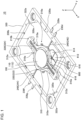
- FIG.1 is a perspective view in which an optical scanning device 10 according to an embodiment is viewed from a side on which a movable reflector 100 is located.
- FIG.2 is a perspective view in which the optical scanning device 10 according to the embodiment is viewed from a side opposite to a side on which the movable reflector 100 is located.
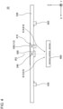
- FIG.3 is a side view in which the optical scanning device 10 according to the embodiment is viewed from a direction parallel to a rotation axis of the movable reflector 100.
- FIG.4 is a side view in which the optical scanning device 10 according to the embodiment is viewed from a direction parallel to a rotation axis of a first frame body 210.
- FIG.5 is a cross-sectional view taken along line A-A of FIG.3 .
- an arrow indicating a first direction X, a second direction Y, or a third direction Z indicates that a direction from a base end to a tip of the arrow is a positive direction of the direction indicated by the arrow and that a direction from the tip to the base end of the arrow is a negative direction of the direction indicated by the arrow.
- a white circle with a black dot indicating the first direction X or the second direction Y indicates that a direction from a far side to a near side of the page is the positive direction of the direction indicated by the white circle, and that a direction from the near side to the far side of the page is the negative direction of the direction indicated by the white circle.
- a white circle with an X mark, indicating the third direction Z indicates that the direction from the near side to the far side of the page is the positive direction of the direction indicated by the white circle, and that the direction from the far side to the near side of the page is the negative direction of the direction indicated by the white circle.
- the first direction X indicates a direction parallel to the rotation axis of the movable reflector 100 when the movable reflector 100 rotates with first torsion bars 220 as the rotation axis with respect to the first frame body 210.
- the positive direction of the first direction X is a direction parallel to a direction from a second bar 224 to a first bar 222, which is described later.
- the negative direction of the first direction X is parallel to a direction from the first bar 222 to the second bar 224.
- the second direction Y is orthogonal to the first direction X.
- the second direction Y indicates a direction parallel to a rotation axis of the first frame body 210 when the first frame body 210 rotates with second torsion bars 240 as the rotation axis with respect to a second frame body 230.
- the positive direction of the second direction Y is parallel to a direction from a fourth bar 244 to a third bar 242, which is later-described.
- the negative direction of the second direction Y is parallel to a direction from the third bar 242 to the fourth bar 244.
- the third direction Z is orthogonal to both of the first direction X and the second direction Y.
- the positive direction of the third direction Z is a direction from a side on which a reflecting surface 112 of the movable reflector 100 is located to a side opposite to the side on which the reflecting surface 112 of the movable reflector 100 is located.
- the negative direction of the third direction Z is a direction from the side on which the reflecting surface 112 of the movable reflector 100 is located to the side on which the reflecting surface 112 of the movable reflector 100 is located.
- the optical scanning device 10 includes the movable reflector 100, the first frame body 210, a pair of the first torsion bars 220, the second frame body 230, a pair of the second torsion bars 240, a first resin body 310, a second resin body 320, a first magnet 410, two second magnets 420, a first light-emitting element 500, and a first light detection element 600.
- the pair of first torsion bars 220 include the first bar 222 and the second bar 224.
- the pair of second torsion bars 240 include the third bar 242 and the fourth bar 244.
- the movable reflector 100 includes a reflector 110, a first supporting unit 252, a second supporting unit 254, and a resin stage 350.
- the reflector 110 has a circular-plate shape having a thickness in the third direction Z.
- the reflector 110 includes the reflecting surface 112.
- the reflecting surface 112 is a flat surface that is oriented toward the positive direction of the third direction Z.
- a shape of the movable reflector 100 is not limited to the shape according to the present embodiment.
- the first supporting unit 252 is made of metal.
- the first supporting unit 252 is connected to an end portion, in the negative direction of the first direction X, of the first bar 222. With respect to the center of the movable reflector 100 in the first direction X, the first supporting unit 252 is located on a positive direction side of the first direction X.
- the second supporting unit 254 is made of metal.
- the second supporting unit 254 is connected to an end portion, in the positive direction of the first direction X, of the second bar 224. With respect to the center of the movable reflector 100 in the first direction X, the second supporting unit 254 is located on a negative direction side of the first direction X.
- the first supporting unit 252 and the second supporting unit 254 are symmetrically arranged with respect to a central axis that passes through the center of the movable reflector 100 in the third direction Z.
- the resin stage 350 is provided over at least a part of the first supporting unit 252 and at least a part of the second supporting unit 254. Specifically, a portion of the resin stage 350 located on the negative direction side of the third direction Z of the first supporting unit 252 and the second supporting unit 254 covers at least a part of surfaces, on the negative direction side of the third direction Z, of the first supporting unit 252 and the second supporting unit 254. Further, a portion of the resin stage 350 located on the positive direction side of the third direction Z of the first supporting unit 252 and the second supporting unit 254 covers at least a part of surfaces, on the positive direction side of the third direction Z, of the first supporting unit 252 and the second supporting unit 254.
- a portion of the resin stage 350 that surrounds the first supporting unit 252 and the second supporting unit 254 in a direction perpendicular to the third direction Z covers at least a part of outer edges, facing in the direction perpendicular to the third direction Z, of the first supporting unit 252 and the second supporting unit 254.
- three supporting protrusions 352 are provided on a surface, on a positive direction side of the third direction Z, of the resin stage 350.
- the reflector 110 is mounted on the three supporting protrusions 352.
- the resin stage 350 in comparison with a case where the resin stage 350 is not provided for the first supporting unit 252 and the second supporting unit 254, accuracy of installation of the reflector 110 can be improved.
- a warp may be generated in the first supporting unit 252 and the second supporting unit 254.
- the resin stage 350 it is possible to suppress the warp in the first supporting unit 252 and the second supporting unit 254.
- a burr may exist in the first supporting unit 252 and the second supporting unit 254.
- the resin stage 350 in a case where the resin stage 350 is provided, it is possible to cover the burr made in the first supporting unit 252 and the second supporting unit 254 with the resin stage 350.
- the resin stage 350 can function as a guiding member to determine mounting positions of the first magnet 410 and the first light detection element 600. Therefore, in comparison with a case where the resin stage 350 is not provided for the first supporting unit 252 and the second supporting unit 254, it is possible to install the first magnet 410 and the first light detection element 600 more easily and more accurately.
- the first supporting unit 252 and the second supporting unit 254 can be physically combined with the resin stage 350.
- the first supporting unit 252 and the second supporting unit 254 communicate with each other, and the first supporting unit 252 and the second supporting unit 254 are electronically connected, even when an anode and a cathode of the first light detection element 600 are electronically connected to the first supporting unit 252 and the second supporting unit 254, current cannot flow through the first light detection element 600, as described later.
- current can flow through the first light detection element 600 by electronically connecting the anode and the cathode of the first light detection element 600 to the first supporting unit 252 and the second supporting unit 254.
- the first frame body 210 is made of metal.
- the first frame body 210 is located in at least a part of a region surrounding the movable reflector 100 in the direction perpendicular to the third direction Z.
- the first bar 222 is made of metal. As shown in FIG.5 , the first bar 222 extends in the first direction X between an outer edge of an end portion, in the positive direction of the first direction X, of the first supporting unit 252 and an inner edge of an end portion, in the positive direction of the first direction X, of the first frame body 210. One end, in the negative direction of the first direction X, of the first bar 222 is connected to the outer edge of the end portion, in the positive direction of the first direction X, of the first supporting unit 252. The other end, in the positive direction of the first direction X, of the first bar 222 is connected to the inner edge of the end portion, in the positive direction of the first direction X, of the first frame body 210.
- the second bar 224 is made of metal. As shown in FIG.5 , the second bar 224 extends in the first direction X between an outer edge of an end portion, in the negative direction of the first direction X, of the second supporting unit 254 and an inner edge of an end portion, in the negative direction of the first direction X, of the first frame body 210. One end, in the positive direction of the first direction X, of the second bar 224 is connected to the outer edge of the end portion, in the negative direction of the first direction X, of the second supporting unit 254. The other end, in the negative direction of the first direction X, of the second bar 224 is connected to the inner edge of the end portion, in the negative direction of the first direction X, of the first frame body 210.
- the first magnet 410 is installed on a negative direction side of the third direction Z of the movable reflector 100.
- the first magnet 410 is located on the negative direction side of the first direction X with respect to the center of the first direction X and the second direction Y of the movable reflector 100. Since the first magnet 410 receives a magnetic flux emitted from a not-shown magnetic circuit, the movable reflector 100 oscillates with respect to the first frame body 210 with the first torsion bars 220 as the rotation axis.
- the first torsion bars 220 are a high-speed driving shaft.
- the second frame body 230 is made of metal.
- the second frame body 230 is located in at least a part of a region surrounding the first frame body 210 in the direction perpendicular to the third direction Z.
- a shape of the second frame body 230 is a substantial rectangle having a pair of long sides extending in the first direction X and a pair of short sides extending in the second direction Y.
- the shape of the second frame body 230 is not limited to the shape according to the present embodiment.
- the third bar 242 is made of metal. As shown in FIG.5 , the third bar 242 extends in the second direction Y between an outer edge of the center, in the first direction X, of a portion, in the positive direction of the second direction Y, of the first frame body 210 and an inner edge of the center, in the first direction X, of a portion, in the positive direction of the second direction Y, of the second frame body 230.
- One end, in the negative direction of the second direction Y, of the third bar 242 is connected to the outer edge of the center, in the first direction X, of the portion, in the positive direction of the second direction Y, of the first frame body 210.
- the other end, in the positive direction of the second direction Y, of the third bar 242 is connected to the inner edge of the center, in the first direction X, of the portion, in the positive direction of the second direction Y, of the second frame body 230.
- the fourth bar 244 is made of metal. As shown in FIG.5 , the fourth bar 244 extends in the second direction Y between an outer edge of the center, in the first direction X, of a portion, in the negative direction of the second direction Y, of the first frame body 210 and an inner edge of the center, in the first direction X, of a portion, in the negative direction of the second direction Y, of the second frame body 230.
- One end, in the positive direction of the second direction Y, of the third bar 242 is connected to the outer edge of the center, in the first direction X, of the portion, in the negative direction of the second direction Y, of the first frame body 210.
- the other end, in the negative direction of the second direction Y, of the third bar 242 is connected to the inner edge of the center, in the first direction X, of the portion, in the negative direction of the second direction Y, of the second frame body 230.
- the two second magnets 420 are installed on a negative direction side of the third direction Z of the first frame body 210.
- One of the two second magnets 420 is located at the end portion, in the positive direction of the first direction X, of the first frame body 210.
- the other of the two second magnets 420 is located at the end portion, in the negative direction of the first direction X, of the first frame body 210. Since the two second magnets 420 receive magnetic flux emitted from the not-shown magnetic circuit, the first frame body 210 oscillates with the second torsion bars 240 as the rotation axis with respect to the second frame body 230.
- the second torsion bars 240 are a low-speed driving shaft.
- a second direction Y width of the second magnet 420 located at the end portion, in the positive direction of the first direction X, of the first frame body 210 is substantially equal to a second direction Y width of the end portion, in the positive direction of the first direction X, of the first frame body 210.
- the second direction Y width of the second magnet 420 located at the end portion, in the positive direction of the first direction X, of the first frame body 210 is equal to or greater than 95% and equal to or less than 105% of the second direction Y width of the end portion, in the positive direction of the first direction X, of the first frame body 210.
- a not-shown magnetic circuit such as a driving coil or the like is arranged on both sides, in the second direction Y, of the end portion, in the positive direction of the first direction X, of the first frame body 210. Therefore, according to the present embodiment, in comparison with a case where the second direction Y width of the second magnet 420 is shorter than the second direction Y width of the end portion, in the positive direction of the first direction X, of the first frame body 210, it is possible to make the magnetic circuit and the second magnet 420 to be closer to each other.
- a weight of the second magnet 420 in comparison with a case where the second direction Y width of the second magnet 420 is longer than the second direction Y width of the end portion, in the positive direction of the first direction X, of the first frame body 210, a weight of the second magnet 420 can be made lighter.
- the second direction Y width of the second magnet 420 is not limited to the example described above.
- the second direction Y width of the second magnet 420 may be longer than the second direction Y width of the end portion, in the positive direction of the first direction X, of the first frame body 210.
- the magnetic circuit and the second magnet 420 can be made close to each other more easily.
- a second direction Y width of the second magnet 420 located at the end portion, in the negative direction of the first direction X, of the first frame body 210 is substantially equal to a second direction Y width of the end portion, in the negative direction of the first direction X, of the first frame body 210 in the same manner as the second direction Y width of the second magnet 420 located at the end portion, in the positive direction of the first direction X, of the first frame body 210.
- Locations at which the two second magnets 420 are provided are not limited to the locations according to the present embodiment.
- the second magnet 420 located on the positive direction side of the first direction X may be located on the negative direction side of the first direction X with respect to the end portion, in the positive direction side of the first direction X, of the first frame body 210.
- the second direction Y width of the second magnet 420 may be substantially equal to a second direction Y width of a portion of the first frame body 210 at which the second magnet 420 is provided.
- the first resin body 310 is provided over at least a part of the first frame body 210.
- the first resin body 310 covers at least a part of a surface, on the positive direction side of the third direction Z, of the first frame body 210, at least a part of a surface, on the negative direction side of the third direction Z, of the first frame body 210, at least a part of an inner edge, facing in a direction perpendicular to the third direction Z, of the first frame body 210, and at least a part of an outer edge, facing in the direction perpendicular to the third direction Z, of the first frame body 210.
- the material of the first frame body 210 and the material of the first resin body 310 are different. Therefore, a resonance frequency of the first frame body 210 and a resonance frequency of the first resin body 310 are different. Thus, in comparison with the case where the first resin body 310 is not provided, it is possible to dump a resonance mode of the first frame body 210, that is, the unnecessary vibration.
- the first resin body 310 can function as the guiding member to determine the mounting positions of the two second magnets 420. Therefore, in comparison with the case where the first resin body 310 is not provided over the first frame body 210, it is possible to install the two second magnets 420 more easily and more accurately.
- the second resin body 320 is provided over at least a part of the second frame body 230.
- the second resin body 320 covers at least a part of a surface, on the positive direction side of the third direction Z, of the second frame body 230, at least a part of a surface, on the negative direction side of the third direction Z, of the second frame body 230, at least a part of an inner edge, facing in a direction perpendicular to the third direction Z, of the second frame body 230, and at least a part of an outer edge, facing in the direction perpendicular to the third direction Z, of the second frame body 230.
- a second direction Y distance between both portions, opposing to each other in a direction parallel to the rotation axis of the first frame body 210, of the first frame body 210 decreases in at least a part of the first frame body 210 as going away from the rotation axis toward the positive direction of the first direction X and the negative direction side of the first direction X.
- a second direction Y distance between portions of the first frame body 210, located on both sides, in the second direction Y, of the reflector 110 decreases as advancing from the center of the first direction X of the reflector 110 toward an end portion, in the positive direction of the first direction X, of the movable reflector 100 and an end portion, in the negative direction of the first direction X, of the movable reflector 100, along a second direction Y width of the movable reflector 100.
- a second direction Y distance between portions of the first frame body 210 located on both sides, in the second direction Y, of the first bar 222 is constant from the end, in the negative direction of the first direction X, of the first bar 222 to the other end, in the positive direction of the first direction X, of the first bar 222.
- a second direction Y distance between portions of the first frame body 210 located on both sides, in the second direction Y, of the second bar 224 is constant from the one end, in the positive direction of the first direction X, of the second bar 224 to the other end, in the negative direction of the first direction X, of the second bar 224.
- the present embodiment is compared with a case where the second direction Y distance between the both portions of the first frame body 210 opposing to each other in the direction parallel to the rotation axis of the first frame body 210 is constant from the rotation axis to the end portion, in the positive direction or the negative direction of the first direction X, of the first frame body 210.
- making a first direction X length of the first torsion bar 220 longer is allowed.
- a specific example is as follows. That is, making the first direction X length of the first torsion bar 220 relatively long may be necessary.
- the mass of the end portion, in the positive direction of the first direction X, of the first frame body 210 and the mass of the end portion, in the negative direction of the first direction X, of the first frame body 210 can be made small. Therefore, in the present embodiment, in comparison with the case described above, it is possible to make the first direction X length of the first torsion bar 220 to suppress the above-mentioned moment of inertia to a level equal to or less than a certain value longer.
- the shape of the first frame body 210 is not limited to the shape according to the present embodiment.
- the second direction Y distance between the both portions of the first frame body 210 opposing to each other in the direction parallel to the rotation axis of the first frame body 210 may be constant from the rotation axis of the first frame body 210 to the end portion, in the positive direction or the negative direction of the first direction X, of the first frame body 210.
- first protrusions 210a four pairs of first protrusions 210a, four pairs of second protrusions 230a, two third protrusions 210b, two fourth protrusions 230b, two fifth protrusions 250c, and two sixth protrusions 210c will be explained.
- each pair of first protrusions 210a includes two protrusions. Two pairs of the first protrusions 210a are provided at an outer edge of a portion of the first frame body 210 surrounding a portion, in the positive direction of the second direction Y, of the movable reflector 100 in the direction perpendicular to the third direction Z. These two pairs of first protrusions 210a are located on both sides of the first direction X with respect to the center, in the first direction X, of the portion of the first frame body 210.
- a tip of each of the first protrusions 210a is exposed from an outer edge of a portion of the first resin body 310 surrounding the portion, in the positive direction of the second direction Y, of the movable reflector 100 in the direction perpendicular to the third direction Z.
- the other two pairs of the first protrusions 210a are provided at an outer edge of a portion of the first frame body 210 surrounding a portion, in the negative direction of the second direction Y, of the movable reflector 100 in the direction perpendicular to the third direction Z.
- These two pairs of first protrusions 210a are located on the both sides of the first direction X with respect to the center, in the first direction X, of the portion of the first frame body 210.
- a tip of each of the first protrusions 210a is exposed from an outer edge of a portion of the first resin body 310 surrounding the portion, in the negative direction of the second direction Y, of the movable reflector 100 in the direction perpendicular to the third direction Z.
- each pair of second protrusions 230a includes two protrusions. Two pairs of the second protrusions 230a are provided at an inner edge of a portion of the second frame body 230 located on the positive direction side of the second direction Y with respect to the first frame body 210. These two pairs of second protrusions 230a are located on both sides of the first direction X with respect to the center, in the first direction X, of the portion of the second frame body 230. A tip of each of the second protrusions 230a is exposed from an inner edge of a portion of the second resin body 320 located on the positive direction side of the second direction Y with respect to the first frame body 210.
- Two pairs of the second protrusions 230a are provided at an inner edge of a portion of the second frame body 230 located on the negative direction side of the second direction Y with respect to the first frame body 210. These two pairs of second protrusions 230a are located on both sides of the first direction X with respect to the center, in the first direction X, of the portion of the second frame body 230. A tip of each of the second protrusions 230a is exposed from an inner edge of a portion of the second resin body 320 located on the negative direction side of the second direction Y with respect to the first frame body 210.
- a third protrusion 210b is provided at an outer edge of the end portion, in the positive direction of the first direction X, of the first frame body 210. This third protrusion 210b is exposed from an outer edge of an end portion, in the positive direction of the first direction X, of the first resin body 310.
- the other third protrusion 210b is provided at an outer edge of an end portion, in the negative direction of the first direction X, of the first frame body 210.
- This third protrusion 210b is exposed from an outer edge of an end portion, in the negative direction of the first direction X, of the first resin body 310.
- a fourth protrusion 230b is provided at an inner edge of the center, in the second direction Y, of a portion of the second frame body 230 located on the positive direction side of the first direction X with respect to the first frame body 210.
- This fourth protrusion 230b is exposed from an inner edge of the center, in the second direction Y, of a portion of the second resin body 320 located on the positive direction side of the first direction X with respect to the first frame body 210.
- the other fourth protrusion 230b is provided at an inner edge of the center, in the second direction Y, of a portion of the second frame body 230 located on the negative direction side of the first direction X with respect to the first frame body 210.
- This fourth protrusion 230b is exposed from an inner edge of the center, in the second direction Y, of a portion of the second resin body 320 located on the negative direction side of the first direction X with respect to the first frame body 210.
- a fifth protrusion 250c is provided at an end portion, on the negative direction side of the first direction X, of the first supporting unit 252. A tip of this fifth protrusion 250c is exposed from an outer edge, on the negative direction side of the second direction Y, of the resin stage 350.
- the other fifth protrusion 250c is provided on the positive direction side of the first direction X of the second supporting unit 254. A tip of this fifth protrusion 250c is exposed from an outer edge, on the positive direction side of the second direction Y, of the resin stage 350.
- a sixth protrusion 210c is provided at an inner edge of the center, in the first direction X, of the portion of the first frame body 210 surrounding the portion, in the positive direction of the second direction Y, of the movable reflector 100 in the direction perpendicular to the third direction Z.
- This sixth protrusion 210c is exposed from the inner edge of the center, in the first direction X, of the portion of the first resin body 310 surrounding the portion, in the positive direction of the second direction Y, of the movable reflector 100 in the direction perpendicular to the third direction Z.
- the other sixth protrusion 210c is provided at an inner edge of the center, in the first direction X, of the portion of the first frame body 210 surrounding the portion, in the negative direction of the second direction Y, of the movable reflector 100 in the direction perpendicular to the third direction Z.
- This sixth protrusion 210c is exposed from an inner edge of the center, in the first direction X, of the portion of the first resin body 310 surrounding the portion, in the negative direction of the second direction Y, of the movable reflector 100 in the direction perpendicular to the third direction Z.
- protrusions of these protrusions need not be provided.
- the two third protrusions 210b and the two fourth protrusions 230b need not be provided.
- the two fifth protrusions 250c and the two sixth protrusions 210c need not be provided.
- the first terminal 230d is provided at an outer edge of the center, in the first direction X, of the portion of the second frame body 230 located on the positive direction side of the second direction Y with respect to the first frame body 210.
- a tip of the first terminal 230d is exposed from an outer edge of the center, in the first direction X, of the portion of the second resin body 320 located on the positive direction side of the second direction Y with respect to the first frame body 210.
- the seventh protrusion 230e is provided at an outer edge of a portion of the second frame body 230 located on the positive direction side of the second direction Y with respect to the first frame body 210 and located, with respect to the center in the first direction X, on the negative direction side of the first direction X.
- a tip of the seventh protrusion 230e is exposed from an outer edge of a portion of the second resin body 320 located on the positive direction side of the second direction Y with respect to the first frame body 210 and located, with respect to the center in the first direction X, on the negative direction side of the first direction X.
- the second terminal 230f is provided at an outer edge of the center, in the first direction X, of the portion of the second frame body 230 located on the negative direction side of the second direction Y with respect to the first frame body 210.
- a tip of the second terminal 230f is exposed from an outer edge of the center, in the first direction X, of the portion of the second resin body 320 located on the negative direction side of the second direction Y with respect to the first frame body 210.
- the eighth protrusion 230g is provided at an outer edge of the portion of the second frame body 230 located on the negative direction side of the second direction Y with respect to the first frame body 210 and located, with respect to the center in the first direction X, on the positive direction side of the first direction X.
- a tip of the eighth protrusion 230g is exposed from an outer edge of a portion of the second resin body 320 located on the negative direction side of the second direction Y with respect to the first frame body 210 and located, with respect to the center in the first direction X, on the positive direction side of the first direction X.
- a first dividing portion 212 is provided on the positive direction side of the second direction Y of the first frame body 210 with respect to the rotation axis of the movable reflector 100.
- this first dividing portion 212 is provided in a portion of the first frame body 210 surrounding a portion, in the negative direction of the first direction X and the positive direction of the second direction Y, of the movable reflector 100 in the direction perpendicular to the third direction Z.
- the other first dividing portion 212 is provided on the negative direction side of the second direction Y of the first frame body 210 with respect to the rotation axis of the movable reflector 100.
- this first dividing portion 212 is provided in a portion of the first frame body 210 surrounding a portion, in the positive direction of the first direction X and the negative direction of the second direction Y, of the movable reflector 100, in the direction perpendicular to the third direction Z.
- first bar 222 and the second bar 224 are not electronically connected to each other through the first frame body 210.
- a second dividing portion 232 is provided on the positive direction side of the first direction X of the second frame body 230 with respect to the rotation axis of the first frame body 210.
- this second dividing portion 232 is provided between the second terminal 230f and the eighth protrusion 230g.
- the other second dividing portion 232 is provided on the negative direction side of the first direction X of the second frame body 230 with respect to the rotation axis of the first frame body 210.
- this second dividing portion 232 is provided between the first terminal 230d and the seventh protrusion 230e.
- the third bar 242 and the fourth bar 244 are not electronically connected to each other through the second frame body 230.
- a first wide-width portion 310a is provided in a portion of the first resin body 310 in which a curvature of the first frame body 210 changes.
- the first wide-width portion 310a is provided on the outside of an outer edge of the first frame body 210.
- an amount of resin in the portion of the first resin body 310 in which the curvature of the first frame body 210 changes is larger than an amount of resin in the surroundings of the portion of the first resin body 310 in which the curvature of the first frame body 210 changes.
- a large stress is easily added to the first resin body 310 around a portion of the first frame body 210 at which the curvature thereof changes in comparison with the surroundings of the portion of the first frame body 210.
- the present embodiment in comparison with a case where the first wide-width portion 310a is not provided in the portion of the first resin body 310 in which the curvature of the first frame body 210 changes, it is possible to improve strength of the first resin body 310.
- one of the four first wide-width portions 310a is located between a portion of the first frame body 210 that is curved along the outer edge, on the positive direction side of the first direction X and the positive direction side the second direction Y, of the movable reflector 100 and a portion of the first frame body 210 that linearly extends on the positive direction side of the second direction Y with respect to the first bar 222 in parallel to the first direction X.
- Another one of the four first wide-width portions 310a is located between a portion of the first frame body 210 that is curved along the outer edge, on the negative direction side of the first direction X and the positive direction side of the second direction Y, of the movable reflector 100 and a portion of the first frame body 210 that linearly extends on the positive direction side of the second direction Y with respect to the second bar 224 in parallel to the first direction X.
- Another one of the four first wide-width portions 310a is located between a portion of the first frame body 210 that is curved along the outer edge, on the negative direction side of the first direction X and the negative direction side of the second direction Y, of the movable reflector 100 and a portion of the first frame body 210 that linearly extends on the negative direction side of the second direction Y with respect to the second bar 224 in parallel to the first direction X.
- the other one of the four first wide-width portions 310a is located between a portion of the first frame body 210 that is curved along the outer edge, on the positive direction side of the first direction X and the negative direction side of the second direction Y, of the movable reflector 100 and a portion of the first frame body 210 that linearly extends on the negative direction side of the second direction Y with respect to the first bar 222 in parallel to the first direction X.
- a configuration that causes the amount of the resin in the portion of the first resin body 310 in which the curvature of the first frame body 210 changes to be larger than the amount of the resin in the surroundings of the portion of the first resin body 310 in which the curvature of the first frame body 210 changes is not limited to the present embodiment.
- a thickness in the third direction Z of the first resin body 310 in which the curvature of the first frame body 210 changes may be thicker than a thickness in the third direction Z of the first resin body 310 in the surroundings of the portion in which the curvature of the first frame body 210 changes.
- a first hole 312a is provided on an upper surface, in the third direction Z, of the first wide-width portion 310a located on the positive direction side of the first direction X and the negative direction side of the second direction Y with respect to the center of the first direction X and the second direction Y of the first resin body 310.
- the other first hole 312a is provided on the upper surface, in the third direction Z, of the first wide-width portion 310a located on the negative direction side of the first direction X and the negative direction side of the second direction Y with respect to the center of the first direction X and the second direction Y of the first resin body 310.
- none of the first holes 312a are overlapped with the first frame body 210 when viewed in the third direction Z.
- a relatively large pressure is added to the gate from which the resin is injected. Therefore, in a case where the first hole 312a overlaps the first frame body 210 when viewed in the third direction Z, there is a risk of the first frame body 210 being deformed due to the pressure of the resin.
- a location at which the first hole 312a is provided is not limited to the location according to the present embodiment.
- the first hole 312a may be overlapped with the first frame body 210 when viewed in the third direction Z.
- the two first holes 312a are symmetrically arranged with respect to the center of the first direction X and the second direction Y of the first resin body 310.
- the first hole 312a of the two first holes 312a located on the positive direction side of the second direction Y is referred to as one first hole 312a.
- the first hole 312a of the two first holes 312a located on the negative direction side of the second direction Y is referred to as the other first hole 312a.
- a portion of the first frame body 210 located on the positive direction side of the second direction Y with respect to the center of the second direction Y of the first frame body 210 is referred to as one side-portion of the first frame body 210.
- a portion of the first frame body 210 located on the negative direction side of the second direction Y with respect to the center of the second direction Y of the first frame body 210 is referred to as the other side-portion of the first frame body 210.
- a portion of the first frame body 210 connected to an end portion, in the positive direction of the first direction X, of the first bar 222 is referred to as a connecting portion between the first frame body 210 and the first bar 222.
- a portion of the first frame body 210 connected to an end portion, in the negative direction of the first direction X, of the second bar 224 is referred to as a connecting portion between the first frame body 210 and the second bar 224.
- the one first hole 312a is located to be shifted from a point on the one side-portion of the first frame body 210 which is equidistant in a circumferential direction of the first frame body 210 from the connecting portion between the first frame body 210 and the first bar 222 and the connecting portion between the first frame body 210 and the second bar 224.
- the point on the one side-portion of the first frame body 210 which is equidistant in the circumferential direction of the first frame body 210 from the connecting portion between the first frame body 210 and the first bar 222 and the connecting portion between the first frame body 210 and the second bar 224 is the center, in the first direction X, of the one side-portion of the first frame body 210.
- the other first hole 312a is located to be shifted from a point on the other side-portion of the first frame body 210 which is equidistant in the circumferential direction of the first frame body 210 from the connecting portion between the first frame body 210 and the first bar 222 and the connecting portion between the first frame body 210 and the second bar 224.
- the point on the other side-portion of the first frame body 210 which is equidistant in the circumferential direction of the first frame body 210 from the connecting portion between the first frame body 210 and the first bar 222 and the connecting portion between the first frame body 210 and the second bar 224 is the center, in the first direction X, of the other side-portion of the first frame body 210.
- the resin for forming the first resin body 310 in a case where the resin for forming the first resin body 310 is injected from the two first holes 312a, it is possible to cause a weld of the resin to be formed in a portion that is different from the connecting portion between the first frame body 210 and the first bar 222 and a portion that is different from the first frame body 210 and the second bar 224. Therefore, in comparison with a case where the weld is formed over the connecting portion between the first frame body 210 and the first bar 222 and the connecting portion between the first frame body 210 and the second bar 224, it is possible to suppress a damage to the first resin body 310.
- the first hole 312a is not provided on an upper surface, in the third direction Z, of the first wide-width portion 310a located on the negative direction side of the first direction X and the positive direction side of the second direction Y with respect to the center of the first direction X and the second direction Y of the first resin body 310.
- the first hole 312a is not provided on an upper surface, in the third direction Z, of the first wide-width portion 310a located on the positive direction side of the first direction X and the negative direction side of the second direction Y with respect to the center of the first direction X and the second direction Y of the first resin body 310.
- the two first wide-width portions 310a in which the first hole 312a is not provided are symmetrically arranged with respect to the center of the second direction Y of the first resin body 310 with respect to the two first wide-width portions 310a in which the first hole 312a is provided. Therefore, in comparison with a case where the two first wide-width portions 310a in which the first hole 312a is provided are provided without the two first wide-width portions 310a in which the first hole 312a is not provided being provided, it is possible to easily make the first resin body 310 consistent.
- a second wide-width portion 310b is provided for the first resin body 310 on the connecting portion between the end portion, in the positive direction of the first direction X, of the first frame body 210 and the end portion, in the positive direction of the first direction X, of the first bar 222.
- the other second wide-width portion 310b is provided for the first resin body 310 on the connecting portion between the end portion, in the negative direction of the first direction X, of the first frame body 210 and the end portion, in the negative direction of the first direction X, of the second bar 224.
- an amount of the resin in a portion of the first resin body 310 on the connecting portion between the first frame body 210 and the first torsion bar 220 is larger than an amount of the resin in a portion of the first resin body 310 on the surroundings of the connecting portion.
- the large stress is easily added to the first resin body 310 on the connecting portion of the first frame body 210. Therefore, according to the present embodiment, in comparison with a case where the second wide-width portion 310b is not provided for the first resin body 310 on the connecting portion between the first frame body 210 and the first torsion bar 220, it is possible to improve the strength of the first resin body 310.
- a configuration that causes the amount of the resin in the portion of the first resin body 310 on the connecting portion between the first frame body 210 and the first torsion bar 220 to be larger than the amount of the resin in the portion of the first resin body 310 on the surroundings of the connecting portion is not limited to the present embodiment.
- a thickness of the first resin body 310 in the third direction Z on the connecting portion between the first frame body 210 and the first torsion bar 220 may be thicker than a thickness of the first resin body 310 in the third direction Z in the surroundings of the connecting portion.
- a third wide-width portion 310c is provided for the first resin body 310 on a connecting portion between an end portion, in the positive direction of the second direction Y, of the first frame body 210 and an end portion, in the negative direction of the second direction Y, of the third bar 242.
- the other third wide-width portion 310c is provided for the first resin body 310 on a connecting portion between an end portion, in the negative direction of the second direction Y, of the first frame body 210 and an end portion, in the positive direction of the first direction X, of the fourth bar 244.
- an amount of the resin in a portion of the first resin body 310 on a connecting portion between the first frame body 210 and the second torsion bar 240 is larger than the amount of the resin in a portion of the first resin body 310 on the surroundings of the connecting portion.
- the large stress is easily added to the first resin body 310 on the connecting portion of the first frame body 210. Therefore, according to the present embodiment, in comparison with a case where the third wide-width portion 310c is not provided for the first resin body 310 on the connecting portion between the first frame body 210 and the second torsion bar 240, it is possible to improve the strength of the first resin body 310.
- a configuration that causes the amount of the resin in the portion of the first resin body 310 on the connecting portion between the first frame body 210 and the second torsion bar 240 to be larger than the amount of the resin in the portion of the first resin body 310 on the surroundings of the connecting portions is not limited to the present embodiment.
- a thickness of the first resin body 310 in the third direction Z in the connecting portion between the first frame body 210 and the second torsion bar 240 may be thicker than the thickness of the first resin body 310 in the third direction Z in the surroundings of the connecting portion.
- a fourth wide-width portion 320a is provided on the negative direction side of the first direction X and the positive direction side of the second direction Y with respect to the center of the first direction X and the second direction Y of the second resin body 320.
- the other fourth wide-width portion 320a is provided on the positive direction side of the first direction X and the negative direction side of the second direction Y of the second resin body 320.
- a second hole 322a is provided on a surface, on the positive direction side of the third direction Z, of each of the fourth wide-width portions 320a.
- the fourth wide-width portion 320a is provided on the inside of an inner edge of the first torsion bar 220.
- the fourth wide-width portion 320a is provided as a gate from which a resin for forming the second resin body 320 is injected to a mold for molding the second resin body 320.
- Each of the second holes 322a remains as the inlet from which the resin is injected.
- none of the second holes 322a is overlapped with the second frame body 230 when viewed in the third direction Z. Therefore, as is the case with the reason explained regarding the first hole 312a, in comparison with a case where the second hole 322a overlaps the second frame body 230 when viewed in the third direction Z, it is possible to suppress deformation of the second frame body 230 due to the pressure of the resin.
- a location at which the second hole 322a is provided is not limited to the location according to the present embodiment.
- the second hole 322a may be overlapped with the second frame body 230 when viewed in the third direction Z.
- the two second holes 322a are symmetrically arranged with respect to the center of the first direction X and the second direction Y of the second resin body 320.
- the second hole 322a out of the two second holes 322a located on the positive direction side of the first direction X is referred to as one second hole 322a.
- the second hole 322a out of the two second holes 322a located on the negative direction side of the first direction X is referred to as the other second hole 322a.
- a portion of the second frame body 230 on the positive direction side of the first direction X with respect to the center of the first direction X of the second frame body 230 is referred to as one side-portion of the second frame body 230.
- a portion of the second frame body 230 on the negative direction side of the first direction X with respect to the center of the first direction X of the second frame body 230 is referred to as the other side-portion of the second frame body 230.
- a portion of the second frame body 230 connected to an end portion, in the positive direction of the second direction Y, of the third bar 242 is referred to as a connecting portion between the second frame body 230 and the third bar 242.
- a portion of the second frame body 230 connected to an end portion, in the negative direction of the second direction Y, of the fourth bar 244 is referred to as a connecting portion between the second frame body 230 and the fourth bar 244.
- the one second hole 322a is located to be shifted from the point on the one side-portion of the second frame body 230 which is equidistant in the circumferential direction of the second frame body 230 from the connecting portion between the second frame body 230 and the third bar 242 and the connecting portion between the second frame body 230 and the fourth bar 244.
- the point on the one side-portion of the second frame body 230 which is equidistant in the circumferential direction of the second frame body 230 from the connecting portion between the second frame body 230 and the third bar 242 and the connecting portion between the second frame body 230 and the fourth bar 244 is the center, in the second direction Y, of the one side-portion of the second frame body 230.
- the other second hole 322a is located to be shifted from the point on the other side-portion of the second frame body 230 which is equidistant in the circumferential direction of the second frame body 230 from the connecting portion between the second frame body 230 and the third bar 242 and the connecting portion between the second frame body 230 and the fourth bar 244.
- the point on the other side-portion of the second frame body 230 which is equidistant in the circumferential direction of the second frame body 230 from the connecting portion between the second frame body 230 and the third bar 242 and the connecting portion between the second frame body 230 and the fourth bar 244 is the center of the second direction Y of the other side-portion of the second frame body 230.
- the resin for forming the second resin body 320 in a case where the resin for forming the second resin body 320 is injected from the two second holes 322a, it is possible to cause a weld of the resin to be formed in a portion that is different from the connecting portion between the second frame body 230 and the third bar 242 and a portion that is different from the connecting portion between the second frame body 230 and the fourth bar 244. Therefore, in comparison with a case where the weld is formed in the connecting portion between the second frame body 230 and the third bar 242 and the connecting portion between the second frame body 230 and the fourth bar 244, it is possible to suppress a damage to the second resin body 320.
- the first light-emitting element 500 is installed on a side opposite to the side on which the reflecting surface 112 of the movable reflector 100 is located. Assuming that the first light-emitting element 500 is installed over the reflecting surface 112, a portion of the reflecting surface 112 over which the first light-emitting element 500 is installed cannot reflect light. In contrast, according to the present embodiment, it is possible to cause the reflecting surface 112 not to be covered with the first light-emitting element 500.
- One of an anode and a cathode of the first light-emitting element 500 is electronically connected to at least a portion of the first bar 222 through the first supporting unit 252.
- the other of the anode and the cathode of the first light-emitting element 500 is electronically connected to at least a portion of the second bar 224 through the second supporting unit 254.
- a case will be considered where the anode of the first light-emitting element 500 is electronically connected to at least the one portion of the first bar 222 through the first supporting unit 252, and the cathode of the first light-emitting element 500 is electronically connected to at least the one portion of the second bar 224 through the second supporting unit 254.
- a current can flow from the first terminal 230d to the second terminal 230f via the third bar 242, a portion of the first frame body 210 located on the positive direction side of the first direction X and the positive direction side of the second direction Y with respect to the center of the first direction X and the second direction Y of the first frame body 210, the first bar 222, the first supporting unit 252, the first light-emitting element 500, the second supporting unit 254, the second bar 224, a portion of the first frame body 210 located on the negative direction side of the first direction X and the negative direction side of the second direction Y with respect to the center of the first direction X and the second direction Y of the first frame body 210, and the fourth bar 244.
- the first light detection element 600 is located on the negative direction side of the third direction Z with respect to the first light-emitting element 500.
- the first light detection element 600 includes a first light detection unit 612, a second light detection unit 614, a third light detection unit 616, and a fourth light detection unit 618.
- the first light detection unit 612 and the second light detection unit 614 are located on the positive direction side of the second direction Y with respect to a first virtual plane IP1.
- the third light detection unit 616 and the fourth light detection unit 618 are located on the negative direction side of the second direction Y with respect to the first virtual plane IP1.
- the first virtual plane IP1 passes through the rotation axis of the movable reflector 100 and is perpendicular to the reflecting surface 112.
- the second light detection unit 614 and the third light detection unit 616 are located on the negative direction side of the first direction X with respect to a second virtual plane IP2.
- the first light detection unit 612 and the fourth light detection unit 618 are located on the positive direction side of the first direction X with respect to the second virtual plane IP2.
- the second virtual plane IP2 passes through the rotation axis of the first frame body 210 and is perpendicular to the reflecting surface 112.
- the center of a spot generated in the first light detection element 600 by light emitted from the first light-emitting element 500 corresponds to an intersecting portion of the first virtual plane IP1 and the second virtual plane IP2 on the first light detection element 600.
- an emission area of the first light detection unit 612 out of the spot, an emission area of the second light detection unit 614 out of the spot, an emission area of the third light detection unit 616 out of the spot, and an emission area of the fourth light detection unit 618 out of the spot are equal to each other. Intensity of a signal generated in each of the detection units by the spot becomes higher as the emission area of each of the light detection units out of the spot becomes larger.
- oscillation of the movable reflector 100 can be detected according to the ratio of the intensity of the signal that is generated in each of the first light detection unit 612, the second light detection unit 614, the third light detection unit 616, and the fourth light detection unit 618 by the light emitted from the first light-emitting element 500.
- a swinging angle of the movable reflector 100 in the surroundings of the second torsion bars 240 in a case where the first frame body 210 oscillates with respect to the second frame body 230 with the second torsion bars 240 as the rotation axis is estimated by X_TiltError indicated by a formula (1) below.
- a swinging angle of the movable reflector 100 in the surroundings of the first frame body 210 in a case where the movable reflector 100 oscillates with respect to the first frame body 210 with the first torsion bars 220 as the rotation axis is estimated by Y_TiltError indicated by a formula (2) below.
- X_TiltError A + D ⁇ B ⁇ C / A + B + C + D
- Y_TiltError A + B ⁇ C ⁇ D / A + B + C + D
- A, B, C, and D are the intensity of the signal generated in the first light detection unit 612, the second light detection unit 614, the third light detection unit 616, and the fourth light detection unit 618 by the light emitted from the first light-emitting element 500, respectively.
- a sum of the intensity of the signal generated in the first light detection unit 612 and the intensity of the signal generated in the fourth light detection unit 618 and a sum of the intensity of the signal generated in the second light detection unit 614 and the intensity of the signal generated in the third light detection unit 616 are compared.
- the swinging angle of the movable reflector 100 in the surroundings of the second torsion bars 240 in a case where the first frame body 210 oscillates with respect to the second frame body 230 with the second torsion bars 240 as the rotation axis can be estimated.
- a sum of the intensity of the signal generated in the first light detection unit 612 and the intensity of the signal generated in the second light detection unit 614 and a sum of the intensity of the signal generated in the third light detection unit 616 and the intensity of the signal generated in the fourth light detection unit 618 are compared.
- the swinging angle of the movable reflector 100 in the surroundings of the first torsion bars 220 in a case where the movable reflector 100 oscillates with respect to the first frame body 210 with the first torsion bar 220 as the rotation axis can be estimated.
- a detection method of the oscillation of the movable reflector 100 is not limited to the method according to the present embodiment.
- the first light detection element 600 may include a single light detection unit.
- the single light detection unit is provided on, for example, the positive direction side of the first direction X with respect to the first virtual plane IP1.
- the single light detection unit detects the light emitted from the first light-emitting element 500, it can be said that the normal line of the reflecting surface 112 is inclined toward the negative direction side of the second direction Y with respect to the positive direction of the third direction Z.
- the single light detection unit does not detect the light emitted from the first light-emitting element 500, it can be said that the normal line of the reflecting surface 112 is inclined toward the positive direction side of the second direction Y with respect to the positive direction of the third direction Z.
- the first light-emitting element 500 may be installed over the reflecting surface 112.
- the first light detection element 600 is provided on the positive direction side of the third direction Z of the reflecting surface 112.
- the oscillation of the movable reflector 100 can be detected by using the first light-emitting element 500 and the first light detection element 600.
- FIGs.6 and 7 are drawings explaining an example of a method for manufacturing the optical scanning device 10 according to the embodiment.
- the optical scanning device 10 according to the embodiment is manufactured as follows.
- the metal body 200 includes four first connecting portions 260a, two second connecting portions 260b, two third connecting portions 260c, a first turning back portion 260d, and a second turning back portion 260f.
- the four first connecting portions 260a are connected to the outer edge, facing in a direction perpendicular to the third direction Z, of the first frame body 210 and the inner edge, facing in a direction perpendicular to the third direction Z, of the second frame body 230.
- the first frame body 210 is supported by the second frame body 230 not only with the second torsion bar 240 but also with the four first connecting portions 260a.
- one end of each of the first connecting portions 260a connected to the outer edge of the first frame body 210 is connected to the tip of the first protrusion 210a.
- the other end of each of the first connecting portions 260a connected to the inner edge of the second frame body 230 is connected to the tip of the second protrusion 230a.
- Each of the first connecting portions 260a includes two first narrow-width portions 262a.
- One of the two first narrow-width portions 262a is provided on the one end of a first connecting portion 260a connected to the tip of the first protrusion 210a.
- the other of the two first narrow-width portions 262a is provided on the other end of the first connecting portion 260a connected to the tip of the second protrusion 230a.
- the two second connecting portions 260b are connected to the outer edge, facing in the direction perpendicular to the third direction Z, of the first frame body 210 and the inner edge, facing in the direction perpendicular to the third direction Z, of the second frame body 230.
- the first frame body 210 is supported by the second frame body 230 not only with the second torsion bar 240 but also with the two second connecting portions 260b.
- one end of each of the second connecting portions 260b connected to the outer edge of the first frame body 210 is connected to a tip of the third protrusion 210b.
- the other end of each of the second connecting portions 260b connected to the inner edge of the second frame body 230 is connected to a tip of the fourth protrusion 230b.
- Each of the second connecting portions 260b includes two second narrow-width portions 262b.
- One of the two second narrow-width portions 262b is provided on the one end of the second connecting portion 260b connected to the tip of the third protrusion 210b.
- the other of the two second narrow-width portions 262b is provided on the other end of the second connecting portion 260b connected to the tip of the fourth protrusion 230b.
- One of the two third connecting portions 260c is connected to an outer edge of an end portion, on the negative direction side of the first direction X, of the first supporting unit 252 and an inner edge of a portion, on the negative direction side of the second direction Y, of the first frame body 210.
- the other of the two third connecting portions 260c is connected to an outer edge of an end portion, in the positive direction of the first direction X, of the second supporting unit 254 and an inner edge of a portion, on the positive direction side of the second direction Y, of the first frame body 210.
- each of the third connecting portions 260c connected to the first supporting unit 252 or the second supporting unit 254 is connected to a tip of the fifth protrusion 250c.
- the other end of each of the third connecting portions 260c connected to the inner edge of the first frame body 210 is connected to a tip of the sixth protrusion 210c.
- Each of the third connecting portions 260c includes two third narrow-width portions 262c.
- One of the two third narrow-width portions 262c is provided at the one end of the third connecting portion 260c connected to the tip of the fifth protrusion 250c.
- the other of the two third narrow-width portions 262c is provided at the other end of the third connecting portion 260c connected to the tip of the sixth protrusion 210c.
- the first turning back portion 260d turns back between the first terminal 230d and the seventh protrusion 230e on the outside of the outer edge, in the positive direction of the second direction Y, of the second frame body 230.
- the first turning back portion 260d includes two fourth narrow-width portions 262d. One of the two fourth narrow-width portions 262d is provided at one end of the first turning back portion 260d connected to a tip of the first terminal 230d. The other of the two fourth narrow-width portions 262d is provided at the other end of the first turning back portion 260d connected to a tip of the seventh protrusion 230e.
- the second turning back portion 260f turns back between the second terminal 230f and the eighth protrusion 230g on the outside of the outer edge, in the negative direction of the second direction Y, of the second frame body 230.
- the second turning back portion 260f includes two fifth narrow-width portions 262f. One of the two fifth narrow-width portions 262f is provided at one end of the second turning back portion 260f connected to a tip of the second terminal 230f. The other of the two fifth narrow-width portions 262f is provided at the other end of the second turning back portion 260f connected to a tip of the eighth protrusion 230g.
- the first resin body 310 is formed on the first frame body 210. Specifically, a mold for molding the first resin body 310 is mounted on the first frame body 210, and the resin for forming the first resin body 310 is injected to the mold from the positive direction side of the third direction Z with respect to the first frame body 210.
- the resin is injected from two locations at which the first wide-width portion 310a located on the positive direction side of the first direction X and the positive direction side of the second direction Y with respect to the center of the first direction X and the second direction Y of the first resin body 310 and the first wide-width portion 310a located on the negative direction side of the first direction X and the negative direction side of the second direction Y with respect to the center of the first direction X and the second direction Y of the first resin body 310 are formed.
- the resin is injected from the two locations, thereby the first hole 312a is formed on a surface, on the positive direction side of the third direction Z, of each of the first wide-width portions 310a.
- the second resin body 320 is formed on the second frame body 230.
- a mold for molding the second resin body 320 is mounted on the second frame body 230, and the resin for forming the second resin body 320 is injected to the mold from the positive direction side of the third direction Z with respect to the second frame body 230.
- the resin is injected from two locations at which the two fourth wide-width portions 320a are formed.
- the resin is injected from the two locations, thereby the second hole 322a is formed on a surface, on the positive direction side of the third direction Z, of each of the fourth wide-width portions 320a.
- the resin stage 350 is formed on the first supporting unit 252 and the second supporting unit 254. Specifically, the first supporting unit 252 and the second supporting unit 254 are placed in a mold for molding the resin stage 350, and the resin for forming the resin stage 350 is injected to the mold. The resin is injected from a location that overlaps the first supporting unit 252 when viewed in the third direction Z. The resin is injected from the location, thereby a third hole 352a is formed on the surface, on the positive direction side of the third direction Z, of the resin stage 350.
- each of the first connecting portions 260a is removed by a method such as laser fusing.
- the two first narrow-width portions 262a are cut by a method such as laser fusing.
- the first connecting portions 260a are removed by the method such as the laser fusing such that the tips of the first protrusions 210a do not remain on the outside of the outer edge, facing in a direction perpendicular to the third direction Z, of the first resin body 310, it is possible to suppress a damage to the outer edge, facing in a direction perpendicular to the third direction Z, of the first resin body 310.
- each of the second connecting portions 260b is removed by cutting the two second narrow-width portions 262b of each of the second connecting portions 260b by a method such as a laser fusing.
- each of the third connecting portions 260c is removed by cutting the two third narrow-width portions 262c of each of the third connecting portions 260c by a method such as the laser fusing.
- the first turning back portion 260d is removed by cutting the two fourth narrow-width portions 262d by a method such as the laser fusing.
- the second turning back portion 260f is removed by cutting the two fifth narrow-width portions 262f by a method such as the laser fusing.
- the reflector 110 is placed on the positive direction side of the third direction Z of the three supporting protrusions 352 of the resin stage 350.
- the first magnet 410 and the first light-emitting element 500 are provided on the negative direction side of the third direction Z of the resin stage 350.
- the two second magnets 420 are provided on the negative direction side of the third direction Z of the first resin body 310.
- the first light detection element 600 is provided on the negative direction side of the third direction Z of the first light-emitting element 500.
- the optical scanning device 10 is manufactured.
- FIG.8 is a perspective view of an optical scanning device 10A according to a modification example.
- the optical scanning device 10A according to the present modification example does not include the first light-emitting element 500 and the first light detection element 600 indicated in FIG.1 and FIG.2 .
- FIG.9 is a diagram of a configuration of a sensor device 20 according to an example.
- the sensor device 20 includes an optical scanning device 10 according to the embodiment.
- the sensor device 20 further includes a second light-emitting element 12, a second light detection element 14, and a beam splitter 16.
- the sensor device 20 is a Light Detection And Ranging (LiDAR).
- the second light-emitting element 12 is, for example, a laser diode (LD). As indicated by a solid line arrow that extends from the second light-emitting element 12 via the beam splitter 16 and a movable reflector 100, light emitted from the second light-emitting element 12 passes through the beam splitter 16 and is reflected by the movable reflector 100. The light reflected by the movable reflector 100 is reflected or scattered by a not-shown object that exists in the outside of the optical scanning device 10.
- LD laser diode
- the second light detection element 14 is, for example, an avalanche photo diode (APD). As indicated by a solid line arrow that extends to the second light detection element 14 via the optical scanning device 10 and the beam splitter 16, the second light detection element 14 detects light emitted from the second light-emitting element 12, reflected by the movable reflector 100, and reflected or scattered by the not-shown object that exists in the outside of the optical scanning device 10. In the present example, the light detected by the second light detection element 14 is reflected or scattered by the above-mentioned object, reflected by the movable reflector 100 and the beam splitter 16, and reaches the second light detection element 14.
- APD avalanche photo diode
- a configuration of the sensor device 20 is not limited to the configuration according to the present example.
- an optical axis of light that is reflected by the movable reflector 100 and irradiated to an object that exists in the outside of the optical scanning device 10 and an optical axis of light reflected or scattered by the object match.
- the optical axis of the light that is reflected by the movable reflector 100 and irradiated to the object that exists in the outside of the optical scanning device 10 and the optical axis of the light reflected or scattered by the object may be shifted from each other. In this case, the light reflected or scattered by the object reaches the second light detection element 14 without being reflected on the movable reflector 100.
Landscapes
- Physics & Mathematics (AREA)
- Engineering & Computer Science (AREA)
- General Physics & Mathematics (AREA)
- Computer Networks & Wireless Communication (AREA)
- Radar, Positioning & Navigation (AREA)
- Remote Sensing (AREA)
- Optics & Photonics (AREA)
- Electromagnetism (AREA)
- Non-Portable Lighting Devices Or Systems Thereof (AREA)
- Mechanical Light Control Or Optical Switches (AREA)
Abstract
Description
- The present invention relates to an optical scanning device and a sensor device.
- In recent years, there have been developments in various optical scanning devices. The optical scanning device includes a movable reflector that reflects light emitted from a light-emitting element such as a laser diode (LD). The movable reflector may be formed by processing a semiconductor substrate such as a Silicon On Insulator (SOI) substrate using a semiconductor manufacturing technique. In contrast, as described in, for example, Patent Document 1, the movable reflector may be formed by processing metal.
- Patent Document 1:
Japanese Unexamined Patent Application Publication No. 2010-2777 - A novel structure to detect oscillation of a movable reflector is sometimes requested. For example, in a case where the movable reflector is formed by processing a semiconductor substrate using a semiconductor manufacturing technique, a piezoelectric element to detect the oscillation of the movable reflector may be provided. However, for example, as described in Patent Document 1, in a case where the movable reflector is formed by processing metal, it may be difficult to provide the piezoelectric element. In such a case, it is requested to detect the oscillation of the movable reflector by the novel structure without using the piezoelectric element.
- A problem to be solved by the present invention is to detect oscillation of a movable reflector by a novel structure.
- The invention described in Claim 1 is an optical scanning device including:
- a movable reflector;
- a first light-emitting element installed over the movable reflector; and
- a first light detection element detecting light emitted from the first light-emitting element.
- The invention described in Claim 7 is a sensor device including:
- the optical scanning device;
- a second light-emitting element; and
- a second light detection element that detects light emitted from the second light-emitting element, reflected by the movable reflector, and reflected or scattered by an object that exists outside the optical scanning device.
-
-
FIG.1 is a perspective view in which an optical scanning device according to an embodiment is viewed from a side on which a movable reflector is located. -
FIG.2 is a perspective view in which the optical scanning device according to the embodiment is viewed from a side opposite to the side on which the movable reflector is located. -
FIG.3 is a side view in which the optical scanning device according to the embodiment is viewed from a direction parallel to a rotation axis of the movable reflector. -
FIG.4 is a side view in which the optical scanning device according to the embodiment is viewed from a direction parallel to a rotation axis of a first frame body. -
FIG.5 is a cross-sectional view taken along line A-A ofFIG.3 . -
FIG.6 is a diagram to explain an example of a method for manufacturing the optical scanning device according to the embodiment. -
FIG.7 is a diagram to explain an example of a method for manufacturing the optical scanning device according to the embodiment. -
FIG.8 is a perspective view of an optical scanning device according to a modification example. -
FIG.9 is a diagram indicating a configuration of a sensor device according to an example. - An embodiment, a modification example, and an example of the present invention will be described below with referring to the drawings. Note that in all the drawings, the same constituent elements are given the same reference numerals, and descriptions thereof will not be repeated.
-
FIG.1 is a perspective view in which anoptical scanning device 10 according to an embodiment is viewed from a side on which amovable reflector 100 is located.FIG.2 is a perspective view in which theoptical scanning device 10 according to the embodiment is viewed from a side opposite to a side on which themovable reflector 100 is located.FIG.3 is a side view in which theoptical scanning device 10 according to the embodiment is viewed from a direction parallel to a rotation axis of themovable reflector 100.FIG.4 is a side view in which theoptical scanning device 10 according to the embodiment is viewed from a direction parallel to a rotation axis of afirst frame body 210.FIG.5 is a cross-sectional view taken along line A-A ofFIG.3 . - In
FIGs.1 to 5 , an arrow indicating a first direction X, a second direction Y, or a third direction Z indicates that a direction from a base end to a tip of the arrow is a positive direction of the direction indicated by the arrow and that a direction from the tip to the base end of the arrow is a negative direction of the direction indicated by the arrow. InFIG.3 andFIG.4 , a white circle with a black dot indicating the first direction X or the second direction Y indicates that a direction from a far side to a near side of the page is the positive direction of the direction indicated by the white circle, and that a direction from the near side to the far side of the page is the negative direction of the direction indicated by the white circle. InFIG.5 , a white circle with an X mark, indicating the third direction Z, indicates that the direction from the near side to the far side of the page is the positive direction of the direction indicated by the white circle, and that the direction from the far side to the near side of the page is the negative direction of the direction indicated by the white circle. - The first direction X indicates a direction parallel to the rotation axis of the
movable reflector 100 when themovable reflector 100 rotates withfirst torsion bars 220 as the rotation axis with respect to thefirst frame body 210. The positive direction of the first direction X is a direction parallel to a direction from asecond bar 224 to afirst bar 222, which is described later. The negative direction of the first direction X is parallel to a direction from thefirst bar 222 to thesecond bar 224. The second direction Y is orthogonal to the first direction X. The second direction Y indicates a direction parallel to a rotation axis of thefirst frame body 210 when thefirst frame body 210 rotates withsecond torsion bars 240 as the rotation axis with respect to asecond frame body 230. The positive direction of the second direction Y is parallel to a direction from afourth bar 244 to athird bar 242, which is later-described. The negative direction of the second direction Y is parallel to a direction from thethird bar 242 to thefourth bar 244. The third direction Z is orthogonal to both of the first direction X and the second direction Y. The positive direction of the third direction Z is a direction from a side on which areflecting surface 112 of themovable reflector 100 is located to a side opposite to the side on which thereflecting surface 112 of themovable reflector 100 is located. The negative direction of the third direction Z is a direction from the side on which thereflecting surface 112 of themovable reflector 100 is located to the side on which thereflecting surface 112 of themovable reflector 100 is located. - The
optical scanning device 10 includes themovable reflector 100, thefirst frame body 210, a pair of thefirst torsion bars 220, thesecond frame body 230, a pair of thesecond torsion bars 240, afirst resin body 310, asecond resin body 320, afirst magnet 410, twosecond magnets 420, a first light-emitting element 500, and a firstlight detection element 600. The pair offirst torsion bars 220 include thefirst bar 222 and thesecond bar 224. The pair ofsecond torsion bars 240 include thethird bar 242 and thefourth bar 244. - As shown in
FIG.5 , themovable reflector 100 includes areflector 110, a first supportingunit 252, a second supportingunit 254, and aresin stage 350. - In the present embodiment, the
reflector 110 has a circular-plate shape having a thickness in the third direction Z. Thereflector 110 includes the reflectingsurface 112. The reflectingsurface 112 is a flat surface that is oriented toward the positive direction of the third direction Z. A shape of themovable reflector 100 is not limited to the shape according to the present embodiment. - The first supporting
unit 252 is made of metal. The first supportingunit 252 is connected to an end portion, in the negative direction of the first direction X, of thefirst bar 222. With respect to the center of themovable reflector 100 in the first direction X, the first supportingunit 252 is located on a positive direction side of the first direction X. - The second supporting
unit 254 is made of metal. The second supportingunit 254 is connected to an end portion, in the positive direction of the first direction X, of thesecond bar 224. With respect to the center of themovable reflector 100 in the first direction X, the second supportingunit 254 is located on a negative direction side of the first direction X. In the present embodiment, the first supportingunit 252 and the second supportingunit 254 are symmetrically arranged with respect to a central axis that passes through the center of themovable reflector 100 in the third direction Z. - The
resin stage 350 is provided over at least a part of the first supportingunit 252 and at least a part of the second supportingunit 254. Specifically, a portion of theresin stage 350 located on the negative direction side of the third direction Z of the first supportingunit 252 and the second supportingunit 254 covers at least a part of surfaces, on the negative direction side of the third direction Z, of the first supportingunit 252 and the second supportingunit 254. Further, a portion of theresin stage 350 located on the positive direction side of the third direction Z of the first supportingunit 252 and the second supportingunit 254 covers at least a part of surfaces, on the positive direction side of the third direction Z, of the first supportingunit 252 and the second supportingunit 254. In addition, a portion of theresin stage 350 that surrounds the first supportingunit 252 and the second supportingunit 254 in a direction perpendicular to the third direction Z covers at least a part of outer edges, facing in the direction perpendicular to the third direction Z, of the first supportingunit 252 and the second supportingunit 254. - As shown in later-described
FIG.7 , three supportingprotrusions 352 are provided on a surface, on a positive direction side of the third direction Z, of theresin stage 350. Thereflector 110 is mounted on the three supportingprotrusions 352. - According to the present embodiment, in comparison with a case where the
resin stage 350 is not provided for the first supportingunit 252 and the second supportingunit 254, accuracy of installation of thereflector 110 can be improved. Specifically, in a case where theresin stage 350 is not provided, a warp may be generated in the first supportingunit 252 and the second supportingunit 254. In contrast, in a case where theresin stage 350 is provided, it is possible to suppress the warp in the first supportingunit 252 and the second supportingunit 254. In addition, a burr may exist in the first supportingunit 252 and the second supportingunit 254. In contrast, in a case where theresin stage 350 is provided, it is possible to cover the burr made in the first supportingunit 252 and the second supportingunit 254 with theresin stage 350. - Further, in the present embodiment, the
resin stage 350 can function as a guiding member to determine mounting positions of thefirst magnet 410 and the firstlight detection element 600. Therefore, in comparison with a case where theresin stage 350 is not provided for the first supportingunit 252 and the second supportingunit 254, it is possible to install thefirst magnet 410 and the firstlight detection element 600 more easily and more accurately. - Further, according to the present embodiment, while the first supporting
unit 252 and the second supportingunit 254 are kept in an electronically insulated state, the first supportingunit 252 and the second supportingunit 254 can be physically combined with theresin stage 350. Assuming that the first supportingunit 252 and the second supportingunit 254 communicate with each other, and the first supportingunit 252 and the second supportingunit 254 are electronically connected, even when an anode and a cathode of the firstlight detection element 600 are electronically connected to the first supportingunit 252 and the second supportingunit 254, current cannot flow through the firstlight detection element 600, as described later. In contrast, in the present embodiment, current can flow through the firstlight detection element 600 by electronically connecting the anode and the cathode of the firstlight detection element 600 to the first supportingunit 252 and the second supportingunit 254. - The
first frame body 210 is made of metal. Thefirst frame body 210 is located in at least a part of a region surrounding themovable reflector 100 in the direction perpendicular to the third direction Z. - The
first bar 222 is made of metal. As shown inFIG.5 , thefirst bar 222 extends in the first direction X between an outer edge of an end portion, in the positive direction of the first direction X, of the first supportingunit 252 and an inner edge of an end portion, in the positive direction of the first direction X, of thefirst frame body 210. One end, in the negative direction of the first direction X, of thefirst bar 222 is connected to the outer edge of the end portion, in the positive direction of the first direction X, of the first supportingunit 252. The other end, in the positive direction of the first direction X, of thefirst bar 222 is connected to the inner edge of the end portion, in the positive direction of the first direction X, of thefirst frame body 210. - The
second bar 224 is made of metal. As shown inFIG.5 , thesecond bar 224 extends in the first direction X between an outer edge of an end portion, in the negative direction of the first direction X, of the second supportingunit 254 and an inner edge of an end portion, in the negative direction of the first direction X, of thefirst frame body 210. One end, in the positive direction of the first direction X, of thesecond bar 224 is connected to the outer edge of the end portion, in the negative direction of the first direction X, of the second supportingunit 254. The other end, in the negative direction of the first direction X, of thesecond bar 224 is connected to the inner edge of the end portion, in the negative direction of the first direction X, of thefirst frame body 210. - As shown in
FIG.2 , thefirst magnet 410 is installed on a negative direction side of the third direction Z of themovable reflector 100. Thefirst magnet 410 is located on the negative direction side of the first direction X with respect to the center of the first direction X and the second direction Y of themovable reflector 100. Since thefirst magnet 410 receives a magnetic flux emitted from a not-shown magnetic circuit, themovable reflector 100 oscillates with respect to thefirst frame body 210 with thefirst torsion bars 220 as the rotation axis. In the present embodiment, thefirst torsion bars 220 are a high-speed driving shaft. - The
second frame body 230 is made of metal. Thesecond frame body 230 is located in at least a part of a region surrounding thefirst frame body 210 in the direction perpendicular to the third direction Z. - In the present embodiment, a shape of the
second frame body 230 is a substantial rectangle having a pair of long sides extending in the first direction X and a pair of short sides extending in the second direction Y. The shape of thesecond frame body 230 is not limited to the shape according to the present embodiment. - The
third bar 242 is made of metal. As shown inFIG.5 , thethird bar 242 extends in the second direction Y between an outer edge of the center, in the first direction X, of a portion, in the positive direction of the second direction Y, of thefirst frame body 210 and an inner edge of the center, in the first direction X, of a portion, in the positive direction of the second direction Y, of thesecond frame body 230. One end, in the negative direction of the second direction Y, of thethird bar 242 is connected to the outer edge of the center, in the first direction X, of the portion, in the positive direction of the second direction Y, of thefirst frame body 210. The other end, in the positive direction of the second direction Y, of thethird bar 242 is connected to the inner edge of the center, in the first direction X, of the portion, in the positive direction of the second direction Y, of thesecond frame body 230. - The
fourth bar 244 is made of metal. As shown inFIG.5 , thefourth bar 244 extends in the second direction Y between an outer edge of the center, in the first direction X, of a portion, in the negative direction of the second direction Y, of thefirst frame body 210 and an inner edge of the center, in the first direction X, of a portion, in the negative direction of the second direction Y, of thesecond frame body 230. One end, in the positive direction of the second direction Y, of thethird bar 242 is connected to the outer edge of the center, in the first direction X, of the portion, in the negative direction of the second direction Y, of thefirst frame body 210. The other end, in the negative direction of the second direction Y, of thethird bar 242 is connected to the inner edge of the center, in the first direction X, of the portion, in the negative direction of the second direction Y, of thesecond frame body 230. - The two
second magnets 420 are installed on a negative direction side of the third direction Z of thefirst frame body 210. One of the twosecond magnets 420 is located at the end portion, in the positive direction of the first direction X, of thefirst frame body 210. The other of the twosecond magnets 420 is located at the end portion, in the negative direction of the first direction X, of thefirst frame body 210. Since the twosecond magnets 420 receive magnetic flux emitted from the not-shown magnetic circuit, thefirst frame body 210 oscillates with thesecond torsion bars 240 as the rotation axis with respect to thesecond frame body 230. In the present embodiment, thesecond torsion bars 240 are a low-speed driving shaft. - In the present embodiment, a second direction Y width of the
second magnet 420 located at the end portion, in the positive direction of the first direction X, of thefirst frame body 210 is substantially equal to a second direction Y width of the end portion, in the positive direction of the first direction X, of thefirst frame body 210. For example, the second direction Y width of thesecond magnet 420 located at the end portion, in the positive direction of the first direction X, of thefirst frame body 210 is equal to or greater than 95% and equal to or less than 105% of the second direction Y width of the end portion, in the positive direction of the first direction X, of thefirst frame body 210. A not-shown magnetic circuit such as a driving coil or the like is arranged on both sides, in the second direction Y, of the end portion, in the positive direction of the first direction X, of thefirst frame body 210. Therefore, according to the present embodiment, in comparison with a case where the second direction Y width of thesecond magnet 420 is shorter than the second direction Y width of the end portion, in the positive direction of the first direction X, of thefirst frame body 210, it is possible to make the magnetic circuit and thesecond magnet 420 to be closer to each other. In addition, according to the present embodiment, in comparison with a case where the second direction Y width of thesecond magnet 420 is longer than the second direction Y width of the end portion, in the positive direction of the first direction X, of thefirst frame body 210, a weight of thesecond magnet 420 can be made lighter. The second direction Y width of thesecond magnet 420 is not limited to the example described above. For example, the second direction Y width of thesecond magnet 420 may be longer than the second direction Y width of the end portion, in the positive direction of the first direction X, of thefirst frame body 210. In this case, in comparison with a case where the second direction Y width of thesecond magnet 420 is equal to or less than the second direction Y width of the end portion, in the positive direction of the first direction X, of thefirst frame body 210, the magnetic circuit and thesecond magnet 420 can be made close to each other more easily. - A second direction Y width of the
second magnet 420 located at the end portion, in the negative direction of the first direction X, of thefirst frame body 210 is substantially equal to a second direction Y width of the end portion, in the negative direction of the first direction X, of thefirst frame body 210 in the same manner as the second direction Y width of thesecond magnet 420 located at the end portion, in the positive direction of the first direction X, of thefirst frame body 210. - Locations at which the two
second magnets 420 are provided are not limited to the locations according to the present embodiment. For example, out of the twosecond magnets 420, thesecond magnet 420 located on the positive direction side of the first direction X may be located on the negative direction side of the first direction X with respect to the end portion, in the positive direction side of the first direction X, of thefirst frame body 210. In this case, the second direction Y width of thesecond magnet 420 may be substantially equal to a second direction Y width of a portion of thefirst frame body 210 at which thesecond magnet 420 is provided. - The
first resin body 310 is provided over at least a part of thefirst frame body 210. Thefirst resin body 310 covers at least a part of a surface, on the positive direction side of the third direction Z, of thefirst frame body 210, at least a part of a surface, on the negative direction side of the third direction Z, of thefirst frame body 210, at least a part of an inner edge, facing in a direction perpendicular to the third direction Z, of thefirst frame body 210, and at least a part of an outer edge, facing in the direction perpendicular to the third direction Z, of thefirst frame body 210. In the present embodiment, in comparison with a case where thefirst resin body 310 is not provided over thefirst frame body 210, it is possible to suppress the warp made in thefirst frame body 210. - In the present embodiment, in comparison with the case where the
first resin body 310 is not provided over thefirst frame body 210, it is possible to suppress an unnecessary vibration of thefirst frame body 210. Specifically, the material of thefirst frame body 210 and the material of thefirst resin body 310 are different. Therefore, a resonance frequency of thefirst frame body 210 and a resonance frequency of thefirst resin body 310 are different. Thus, in comparison with the case where thefirst resin body 310 is not provided, it is possible to dump a resonance mode of thefirst frame body 210, that is, the unnecessary vibration. - Further, in the present embodiment, the
first resin body 310 can function as the guiding member to determine the mounting positions of the twosecond magnets 420. Therefore, in comparison with the case where thefirst resin body 310 is not provided over thefirst frame body 210, it is possible to install the twosecond magnets 420 more easily and more accurately. - The
second resin body 320 is provided over at least a part of thesecond frame body 230. Thesecond resin body 320 covers at least a part of a surface, on the positive direction side of the third direction Z, of thesecond frame body 230, at least a part of a surface, on the negative direction side of the third direction Z, of thesecond frame body 230, at least a part of an inner edge, facing in a direction perpendicular to the third direction Z, of thesecond frame body 230, and at least a part of an outer edge, facing in the direction perpendicular to the third direction Z, of thesecond frame body 230. In the present embodiment, in comparison with a case where thesecond resin body 320 is not provided over thesecond frame body 230, it is possible to suppress the warp made in thesecond frame body 230. Therefore, in the present embodiment, in comparison with the case where thesecond resin body 320 is not provided over thesecond frame body 230, it is possible to suppress an unnecessary vibration of thesecond frame body 230. - Next, with reference to
FIG.5 , details of a shape of thefirst frame body 210 will be explained. - In the present embodiment, a second direction Y distance between both portions, opposing to each other in a direction parallel to the rotation axis of the
first frame body 210, of thefirst frame body 210 decreases in at least a part of thefirst frame body 210 as going away from the rotation axis toward the positive direction of the first direction X and the negative direction side of the first direction X. - Specifically, a second direction Y distance between portions of the
first frame body 210, located on both sides, in the second direction Y, of thereflector 110 decreases as advancing from the center of the first direction X of thereflector 110 toward an end portion, in the positive direction of the first direction X, of themovable reflector 100 and an end portion, in the negative direction of the first direction X, of themovable reflector 100, along a second direction Y width of themovable reflector 100. A second direction Y distance between portions of thefirst frame body 210 located on both sides, in the second direction Y, of thefirst bar 222 is constant from the end, in the negative direction of the first direction X, of thefirst bar 222 to the other end, in the positive direction of the first direction X, of thefirst bar 222. A second direction Y distance between portions of thefirst frame body 210 located on both sides, in the second direction Y, of thesecond bar 224 is constant from the one end, in the positive direction of the first direction X, of thesecond bar 224 to the other end, in the negative direction of the first direction X, of thesecond bar 224. - The present embodiment is compared with a case where the second direction Y distance between the both portions of the
first frame body 210 opposing to each other in the direction parallel to the rotation axis of thefirst frame body 210 is constant from the rotation axis to the end portion, in the positive direction or the negative direction of the first direction X, of thefirst frame body 210. In the present embodiment, in comparison with the case described above, making a first direction X length of thefirst torsion bar 220 longer is allowed. A specific example is as follows. That is, making the first direction X length of thefirst torsion bar 220 relatively long may be necessary. On the other hand, the longer the first direction X length of thefirst torsion bar 220 becomes, the longer the first direction X length of thefirst frame body 210 also becomes. The longer the first direction X length of thefirst torsion bar 220 becomes, a moment of inertia of thefirst frame body 210 that rotates with thesecond torsion bars 240 as the rotation axis becomes larger. Further, the larger the mass of the end portion, in the positive direction of the first direction X, of thefirst frame body 210 and the mass of the end portion, in the negative direction of the first direction X, of thefirst frame body 210 become, the larger the moment of inertia becomes. In the present embodiment, in comparison with the case described above, the mass of the end portion, in the positive direction of the first direction X, of thefirst frame body 210 and the mass of the end portion, in the negative direction of the first direction X, of thefirst frame body 210 can be made small. Therefore, in the present embodiment, in comparison with the case described above, it is possible to make the first direction X length of thefirst torsion bar 220 to suppress the above-mentioned moment of inertia to a level equal to or less than a certain value longer. - The shape of the
first frame body 210 is not limited to the shape according to the present embodiment. For example, the second direction Y distance between the both portions of thefirst frame body 210 opposing to each other in the direction parallel to the rotation axis of thefirst frame body 210 may be constant from the rotation axis of thefirst frame body 210 to the end portion, in the positive direction or the negative direction of the first direction X, of thefirst frame body 210. - Then, with reference to
FIG.5 , four pairs offirst protrusions 210a, four pairs ofsecond protrusions 230a, twothird protrusions 210b, twofourth protrusions 230b, twofifth protrusions 250c, and twosixth protrusions 210c will be explained. - In the present embodiment, each pair of
first protrusions 210a includes two protrusions. Two pairs of thefirst protrusions 210a are provided at an outer edge of a portion of thefirst frame body 210 surrounding a portion, in the positive direction of the second direction Y, of themovable reflector 100 in the direction perpendicular to the third direction Z. These two pairs offirst protrusions 210a are located on both sides of the first direction X with respect to the center, in the first direction X, of the portion of thefirst frame body 210. A tip of each of thefirst protrusions 210a is exposed from an outer edge of a portion of thefirst resin body 310 surrounding the portion, in the positive direction of the second direction Y, of themovable reflector 100 in the direction perpendicular to the third direction Z. The other two pairs of thefirst protrusions 210a are provided at an outer edge of a portion of thefirst frame body 210 surrounding a portion, in the negative direction of the second direction Y, of themovable reflector 100 in the direction perpendicular to the third direction Z. These two pairs offirst protrusions 210a are located on the both sides of the first direction X with respect to the center, in the first direction X, of the portion of thefirst frame body 210. A tip of each of thefirst protrusions 210a is exposed from an outer edge of a portion of thefirst resin body 310 surrounding the portion, in the negative direction of the second direction Y, of themovable reflector 100 in the direction perpendicular to the third direction Z. - In the present embodiment, each pair of
second protrusions 230a includes two protrusions. Two pairs of thesecond protrusions 230a are provided at an inner edge of a portion of thesecond frame body 230 located on the positive direction side of the second direction Y with respect to thefirst frame body 210. These two pairs ofsecond protrusions 230a are located on both sides of the first direction X with respect to the center, in the first direction X, of the portion of thesecond frame body 230. A tip of each of thesecond protrusions 230a is exposed from an inner edge of a portion of thesecond resin body 320 located on the positive direction side of the second direction Y with respect to thefirst frame body 210. Two pairs of thesecond protrusions 230a are provided at an inner edge of a portion of thesecond frame body 230 located on the negative direction side of the second direction Y with respect to thefirst frame body 210. These two pairs ofsecond protrusions 230a are located on both sides of the first direction X with respect to the center, in the first direction X, of the portion of thesecond frame body 230. A tip of each of thesecond protrusions 230a is exposed from an inner edge of a portion of thesecond resin body 320 located on the negative direction side of the second direction Y with respect to thefirst frame body 210. - A
third protrusion 210b is provided at an outer edge of the end portion, in the positive direction of the first direction X, of thefirst frame body 210. Thisthird protrusion 210b is exposed from an outer edge of an end portion, in the positive direction of the first direction X, of thefirst resin body 310. The otherthird protrusion 210b is provided at an outer edge of an end portion, in the negative direction of the first direction X, of thefirst frame body 210. Thisthird protrusion 210b is exposed from an outer edge of an end portion, in the negative direction of the first direction X, of thefirst resin body 310. - A
fourth protrusion 230b is provided at an inner edge of the center, in the second direction Y, of a portion of thesecond frame body 230 located on the positive direction side of the first direction X with respect to thefirst frame body 210. Thisfourth protrusion 230b is exposed from an inner edge of the center, in the second direction Y, of a portion of thesecond resin body 320 located on the positive direction side of the first direction X with respect to thefirst frame body 210. The otherfourth protrusion 230b is provided at an inner edge of the center, in the second direction Y, of a portion of thesecond frame body 230 located on the negative direction side of the first direction X with respect to thefirst frame body 210. Thisfourth protrusion 230b is exposed from an inner edge of the center, in the second direction Y, of a portion of thesecond resin body 320 located on the negative direction side of the first direction X with respect to thefirst frame body 210. - A
fifth protrusion 250c is provided at an end portion, on the negative direction side of the first direction X, of the first supportingunit 252. A tip of thisfifth protrusion 250c is exposed from an outer edge, on the negative direction side of the second direction Y, of theresin stage 350. The otherfifth protrusion 250c is provided on the positive direction side of the first direction X of the second supportingunit 254. A tip of thisfifth protrusion 250c is exposed from an outer edge, on the positive direction side of the second direction Y, of theresin stage 350. - A
sixth protrusion 210c is provided at an inner edge of the center, in the first direction X, of the portion of thefirst frame body 210 surrounding the portion, in the positive direction of the second direction Y, of themovable reflector 100 in the direction perpendicular to the third direction Z. Thissixth protrusion 210c is exposed from the inner edge of the center, in the first direction X, of the portion of thefirst resin body 310 surrounding the portion, in the positive direction of the second direction Y, of themovable reflector 100 in the direction perpendicular to the third direction Z. The othersixth protrusion 210c is provided at an inner edge of the center, in the first direction X, of the portion of thefirst frame body 210 surrounding the portion, in the negative direction of the second direction Y, of themovable reflector 100 in the direction perpendicular to the third direction Z. Thissixth protrusion 210c is exposed from an inner edge of the center, in the first direction X, of the portion of thefirst resin body 310 surrounding the portion, in the negative direction of the second direction Y, of themovable reflector 100 in the direction perpendicular to the third direction Z. - Some protrusions of these protrusions need not be provided. For example, the two
third protrusions 210b and the twofourth protrusions 230b need not be provided. Further, the twofifth protrusions 250c and the twosixth protrusions 210c need not be provided. - Next, with reference to
FIG.5 , afirst terminal 230d, aseventh protrusion 230e, asecond terminal 230f, and aneighth protrusion 230g will be explained. - The
first terminal 230d is provided at an outer edge of the center, in the first direction X, of the portion of thesecond frame body 230 located on the positive direction side of the second direction Y with respect to thefirst frame body 210. A tip of thefirst terminal 230d is exposed from an outer edge of the center, in the first direction X, of the portion of thesecond resin body 320 located on the positive direction side of the second direction Y with respect to thefirst frame body 210. - The
seventh protrusion 230e is provided at an outer edge of a portion of thesecond frame body 230 located on the positive direction side of the second direction Y with respect to thefirst frame body 210 and located, with respect to the center in the first direction X, on the negative direction side of the first direction X. A tip of theseventh protrusion 230e is exposed from an outer edge of a portion of thesecond resin body 320 located on the positive direction side of the second direction Y with respect to thefirst frame body 210 and located, with respect to the center in the first direction X, on the negative direction side of the first direction X. - The
second terminal 230f is provided at an outer edge of the center, in the first direction X, of the portion of thesecond frame body 230 located on the negative direction side of the second direction Y with respect to thefirst frame body 210. A tip of thesecond terminal 230f is exposed from an outer edge of the center, in the first direction X, of the portion of thesecond resin body 320 located on the negative direction side of the second direction Y with respect to thefirst frame body 210. - The
eighth protrusion 230g is provided at an outer edge of the portion of thesecond frame body 230 located on the negative direction side of the second direction Y with respect to thefirst frame body 210 and located, with respect to the center in the first direction X, on the positive direction side of the first direction X. A tip of theeighth protrusion 230g is exposed from an outer edge of a portion of thesecond resin body 320 located on the negative direction side of the second direction Y with respect to thefirst frame body 210 and located, with respect to the center in the first direction X, on the positive direction side of the first direction X. - Then, two
first dividing portions 212 and twosecond dividing portions 232 will be explained. - A
first dividing portion 212 is provided on the positive direction side of the second direction Y of thefirst frame body 210 with respect to the rotation axis of themovable reflector 100. In the present embodiment, thisfirst dividing portion 212 is provided in a portion of thefirst frame body 210 surrounding a portion, in the negative direction of the first direction X and the positive direction of the second direction Y, of themovable reflector 100 in the direction perpendicular to the third direction Z. The otherfirst dividing portion 212 is provided on the negative direction side of the second direction Y of thefirst frame body 210 with respect to the rotation axis of themovable reflector 100. In the present embodiment, thisfirst dividing portion 212 is provided in a portion of thefirst frame body 210 surrounding a portion, in the positive direction of the first direction X and the negative direction of the second direction Y, of themovable reflector 100, in the direction perpendicular to the third direction Z. - Since these two
first dividing portions 212 are provided, thefirst bar 222 and thesecond bar 224 are not electronically connected to each other through thefirst frame body 210. - A
second dividing portion 232 is provided on the positive direction side of the first direction X of thesecond frame body 230 with respect to the rotation axis of thefirst frame body 210. In the present embodiment, thissecond dividing portion 232 is provided between thesecond terminal 230f and theeighth protrusion 230g. The othersecond dividing portion 232 is provided on the negative direction side of the first direction X of thesecond frame body 230 with respect to the rotation axis of thefirst frame body 210. In the present embodiment, thissecond dividing portion 232 is provided between thefirst terminal 230d and theseventh protrusion 230e. - Since these two
second dividing portions 232 are provided, thethird bar 242 and thefourth bar 244 are not electronically connected to each other through thesecond frame body 230. - Then, with reference to
FIG.5 , four first wide-width portions 310a, two second wide-width portions 310b, and two third wide-width portions 310c will be explained. - A first wide-
width portion 310a is provided in a portion of thefirst resin body 310 in which a curvature of thefirst frame body 210 changes. In the present embodiment, the first wide-width portion 310a is provided on the outside of an outer edge of thefirst frame body 210. Thereby, an amount of resin in the portion of thefirst resin body 310 in which the curvature of thefirst frame body 210 changes is larger than an amount of resin in the surroundings of the portion of thefirst resin body 310 in which the curvature of thefirst frame body 210 changes. A large stress is easily added to thefirst resin body 310 around a portion of thefirst frame body 210 at which the curvature thereof changes in comparison with the surroundings of the portion of thefirst frame body 210. Therefore, according to the present embodiment, in comparison with a case where the first wide-width portion 310a is not provided in the portion of thefirst resin body 310 in which the curvature of thefirst frame body 210 changes, it is possible to improve strength of thefirst resin body 310. - In the present embodiment, one of the four first wide-
width portions 310a is located between a portion of thefirst frame body 210 that is curved along the outer edge, on the positive direction side of the first direction X and the positive direction side the second direction Y, of themovable reflector 100 and a portion of thefirst frame body 210 that linearly extends on the positive direction side of the second direction Y with respect to thefirst bar 222 in parallel to the first direction X. Another one of the four first wide-width portions 310a is located between a portion of thefirst frame body 210 that is curved along the outer edge, on the negative direction side of the first direction X and the positive direction side of the second direction Y, of themovable reflector 100 and a portion of thefirst frame body 210 that linearly extends on the positive direction side of the second direction Y with respect to thesecond bar 224 in parallel to the first direction X. Another one of the four first wide-width portions 310a is located between a portion of thefirst frame body 210 that is curved along the outer edge, on the negative direction side of the first direction X and the negative direction side of the second direction Y, of themovable reflector 100 and a portion of thefirst frame body 210 that linearly extends on the negative direction side of the second direction Y with respect to thesecond bar 224 in parallel to the first direction X. The other one of the four first wide-width portions 310a is located between a portion of thefirst frame body 210 that is curved along the outer edge, on the positive direction side of the first direction X and the negative direction side of the second direction Y, of themovable reflector 100 and a portion of thefirst frame body 210 that linearly extends on the negative direction side of the second direction Y with respect to thefirst bar 222 in parallel to the first direction X. - A configuration that causes the amount of the resin in the portion of the
first resin body 310 in which the curvature of thefirst frame body 210 changes to be larger than the amount of the resin in the surroundings of the portion of thefirst resin body 310 in which the curvature of thefirst frame body 210 changes is not limited to the present embodiment. For example, a thickness in the third direction Z of thefirst resin body 310 in which the curvature of thefirst frame body 210 changes may be thicker than a thickness in the third direction Z of thefirst resin body 310 in the surroundings of the portion in which the curvature of thefirst frame body 210 changes. - As shown in
FIG.1 , afirst hole 312a is provided on an upper surface, in the third direction Z, of the first wide-width portion 310a located on the positive direction side of the first direction X and the negative direction side of the second direction Y with respect to the center of the first direction X and the second direction Y of thefirst resin body 310. The otherfirst hole 312a is provided on the upper surface, in the third direction Z, of the first wide-width portion 310a located on the negative direction side of the first direction X and the negative direction side of the second direction Y with respect to the center of the first direction X and the second direction Y of thefirst resin body 310. The two first wide-width portions 310a in which thefirst hole 312a is provided are provided to serve as gates from which a resin for forming thefirst resin body 310 is injected to a mold for molding thefirst resin body 310. Each of thefirst holes 312a remains as an inlet to inject the resin. - In the present embodiment, none of the
first holes 312a are overlapped with thefirst frame body 210 when viewed in the third direction Z. In the entirety of thefirst resin body 310, a relatively large pressure is added to the gate from which the resin is injected. Therefore, in a case where thefirst hole 312a overlaps thefirst frame body 210 when viewed in the third direction Z, there is a risk of thefirst frame body 210 being deformed due to the pressure of the resin. In contrast, according to the present embodiment, in comparison with a case where thefirst hole 312a overlaps thefirst frame body 210 when viewed in the third direction Z, it is possible to suppress deformation of thefirst frame body 210 due to the pressure of the resin. A location at which thefirst hole 312a is provided is not limited to the location according to the present embodiment. For example, thefirst hole 312a may be overlapped with thefirst frame body 210 when viewed in the third direction Z. - In the present embodiment, the two
first holes 312a are symmetrically arranged with respect to the center of the first direction X and the second direction Y of thefirst resin body 310. - Hereinafter, as necessary, the
first hole 312a of the twofirst holes 312a located on the positive direction side of the second direction Y is referred to as onefirst hole 312a. As necessary, thefirst hole 312a of the twofirst holes 312a located on the negative direction side of the second direction Y is referred to as the otherfirst hole 312a. As necessary, a portion of thefirst frame body 210 located on the positive direction side of the second direction Y with respect to the center of the second direction Y of thefirst frame body 210 is referred to as one side-portion of thefirst frame body 210. As necessary, a portion of thefirst frame body 210 located on the negative direction side of the second direction Y with respect to the center of the second direction Y of thefirst frame body 210 is referred to as the other side-portion of thefirst frame body 210. As necessary, a portion of thefirst frame body 210 connected to an end portion, in the positive direction of the first direction X, of thefirst bar 222 is referred to as a connecting portion between thefirst frame body 210 and thefirst bar 222. As necessary, a portion of thefirst frame body 210 connected to an end portion, in the negative direction of the first direction X, of thesecond bar 224 is referred to as a connecting portion between thefirst frame body 210 and thesecond bar 224. - The one
first hole 312a is located to be shifted from a point on the one side-portion of thefirst frame body 210 which is equidistant in a circumferential direction of thefirst frame body 210 from the connecting portion between thefirst frame body 210 and thefirst bar 222 and the connecting portion between thefirst frame body 210 and thesecond bar 224. In the present embodiment, the point on the one side-portion of thefirst frame body 210 which is equidistant in the circumferential direction of thefirst frame body 210 from the connecting portion between thefirst frame body 210 and thefirst bar 222 and the connecting portion between thefirst frame body 210 and thesecond bar 224 is the center, in the first direction X, of the one side-portion of thefirst frame body 210. - The other
first hole 312a is located to be shifted from a point on the other side-portion of thefirst frame body 210 which is equidistant in the circumferential direction of thefirst frame body 210 from the connecting portion between thefirst frame body 210 and thefirst bar 222 and the connecting portion between thefirst frame body 210 and thesecond bar 224. In the present embodiment, the point on the other side-portion of thefirst frame body 210 which is equidistant in the circumferential direction of thefirst frame body 210 from the connecting portion between thefirst frame body 210 and thefirst bar 222 and the connecting portion between thefirst frame body 210 and thesecond bar 224 is the center, in the first direction X, of the other side-portion of thefirst frame body 210. - In the present embodiment, in a case where the resin for forming the
first resin body 310 is injected from the twofirst holes 312a, it is possible to cause a weld of the resin to be formed in a portion that is different from the connecting portion between thefirst frame body 210 and thefirst bar 222 and a portion that is different from thefirst frame body 210 and thesecond bar 224. Therefore, in comparison with a case where the weld is formed over the connecting portion between thefirst frame body 210 and thefirst bar 222 and the connecting portion between thefirst frame body 210 and thesecond bar 224, it is possible to suppress a damage to thefirst resin body 310. - As shown in
FIG.1 , thefirst hole 312a is not provided on an upper surface, in the third direction Z, of the first wide-width portion 310a located on the negative direction side of the first direction X and the positive direction side of the second direction Y with respect to the center of the first direction X and the second direction Y of thefirst resin body 310. Thefirst hole 312a is not provided on an upper surface, in the third direction Z, of the first wide-width portion 310a located on the positive direction side of the first direction X and the negative direction side of the second direction Y with respect to the center of the first direction X and the second direction Y of thefirst resin body 310. The two first wide-width portions 310a in which thefirst hole 312a is not provided are symmetrically arranged with respect to the center of the second direction Y of thefirst resin body 310 with respect to the two first wide-width portions 310a in which thefirst hole 312a is provided. Therefore, in comparison with a case where the two first wide-width portions 310a in which thefirst hole 312a is provided are provided without the two first wide-width portions 310a in which thefirst hole 312a is not provided being provided, it is possible to easily make thefirst resin body 310 consistent. - A second wide-
width portion 310b is provided for thefirst resin body 310 on the connecting portion between the end portion, in the positive direction of the first direction X, of thefirst frame body 210 and the end portion, in the positive direction of the first direction X, of thefirst bar 222. The other second wide-width portion 310b is provided for thefirst resin body 310 on the connecting portion between the end portion, in the negative direction of the first direction X, of thefirst frame body 210 and the end portion, in the negative direction of the first direction X, of thesecond bar 224. Thereby, an amount of the resin in a portion of thefirst resin body 310 on the connecting portion between thefirst frame body 210 and thefirst torsion bar 220 is larger than an amount of the resin in a portion of thefirst resin body 310 on the surroundings of the connecting portion. In comparison with the surroundings of the connecting portion between thefirst frame body 210 andfirst torsion bar 220, the large stress is easily added to thefirst resin body 310 on the connecting portion of thefirst frame body 210. Therefore, according to the present embodiment, in comparison with a case where the second wide-width portion 310b is not provided for thefirst resin body 310 on the connecting portion between thefirst frame body 210 and thefirst torsion bar 220, it is possible to improve the strength of thefirst resin body 310. - A configuration that causes the amount of the resin in the portion of the
first resin body 310 on the connecting portion between thefirst frame body 210 and thefirst torsion bar 220 to be larger than the amount of the resin in the portion of thefirst resin body 310 on the surroundings of the connecting portion is not limited to the present embodiment. For example, a thickness of thefirst resin body 310 in the third direction Z on the connecting portion between thefirst frame body 210 and thefirst torsion bar 220 may be thicker than a thickness of thefirst resin body 310 in the third direction Z in the surroundings of the connecting portion. - A third wide-
width portion 310c is provided for thefirst resin body 310 on a connecting portion between an end portion, in the positive direction of the second direction Y, of thefirst frame body 210 and an end portion, in the negative direction of the second direction Y, of thethird bar 242. The other third wide-width portion 310c is provided for thefirst resin body 310 on a connecting portion between an end portion, in the negative direction of the second direction Y, of thefirst frame body 210 and an end portion, in the positive direction of the first direction X, of thefourth bar 244. Thereby, an amount of the resin in a portion of thefirst resin body 310 on a connecting portion between thefirst frame body 210 and thesecond torsion bar 240 is larger than the amount of the resin in a portion of thefirst resin body 310 on the surroundings of the connecting portion. In comparison with the surroundings of the connecting portion between thefirst frame body 210 and thesecond torsion bar 240, the large stress is easily added to thefirst resin body 310 on the connecting portion of thefirst frame body 210. Therefore, according to the present embodiment, in comparison with a case where the third wide-width portion 310c is not provided for thefirst resin body 310 on the connecting portion between thefirst frame body 210 and thesecond torsion bar 240, it is possible to improve the strength of thefirst resin body 310. - A configuration that causes the amount of the resin in the portion of the
first resin body 310 on the connecting portion between thefirst frame body 210 and thesecond torsion bar 240 to be larger than the amount of the resin in the portion of thefirst resin body 310 on the surroundings of the connecting portions is not limited to the present embodiment. For example, a thickness of thefirst resin body 310 in the third direction Z in the connecting portion between thefirst frame body 210 and thesecond torsion bar 240 may be thicker than the thickness of thefirst resin body 310 in the third direction Z in the surroundings of the connecting portion. - Then, with reference to
FIG.1 andFIG.5 , two fourth wide-width portions 320a will be explained. - A fourth wide-
width portion 320a is provided on the negative direction side of the first direction X and the positive direction side of the second direction Y with respect to the center of the first direction X and the second direction Y of thesecond resin body 320. The other fourth wide-width portion 320a is provided on the positive direction side of the first direction X and the negative direction side of the second direction Y of thesecond resin body 320. Asecond hole 322a is provided on a surface, on the positive direction side of the third direction Z, of each of the fourth wide-width portions 320a. In the present embodiment, the fourth wide-width portion 320a is provided on the inside of an inner edge of thefirst torsion bar 220. The fourth wide-width portion 320a is provided as a gate from which a resin for forming thesecond resin body 320 is injected to a mold for molding thesecond resin body 320. Each of thesecond holes 322a remains as the inlet from which the resin is injected. - In the present embodiment, none of the
second holes 322a is overlapped with thesecond frame body 230 when viewed in the third direction Z. Therefore, as is the case with the reason explained regarding thefirst hole 312a, in comparison with a case where thesecond hole 322a overlaps thesecond frame body 230 when viewed in the third direction Z, it is possible to suppress deformation of thesecond frame body 230 due to the pressure of the resin. A location at which thesecond hole 322a is provided is not limited to the location according to the present embodiment. For example, thesecond hole 322a may be overlapped with thesecond frame body 230 when viewed in the third direction Z. - In the present embodiment, the two
second holes 322a are symmetrically arranged with respect to the center of the first direction X and the second direction Y of thesecond resin body 320. - Hereinafter, as necessary, the
second hole 322a out of the twosecond holes 322a located on the positive direction side of the first direction X is referred to as onesecond hole 322a. As necessary, thesecond hole 322a out of the twosecond holes 322a located on the negative direction side of the first direction X is referred to as the othersecond hole 322a. As necessary, a portion of thesecond frame body 230 on the positive direction side of the first direction X with respect to the center of the first direction X of thesecond frame body 230 is referred to as one side-portion of thesecond frame body 230. As necessary, a portion of thesecond frame body 230 on the negative direction side of the first direction X with respect to the center of the first direction X of thesecond frame body 230 is referred to as the other side-portion of thesecond frame body 230. As necessary, a portion of thesecond frame body 230 connected to an end portion, in the positive direction of the second direction Y, of thethird bar 242 is referred to as a connecting portion between thesecond frame body 230 and thethird bar 242. As necessary, a portion of thesecond frame body 230 connected to an end portion, in the negative direction of the second direction Y, of thefourth bar 244 is referred to as a connecting portion between thesecond frame body 230 and thefourth bar 244. - The one
second hole 322a is located to be shifted from the point on the one side-portion of thesecond frame body 230 which is equidistant in the circumferential direction of thesecond frame body 230 from the connecting portion between thesecond frame body 230 and thethird bar 242 and the connecting portion between thesecond frame body 230 and thefourth bar 244. In the present embodiment, the point on the one side-portion of thesecond frame body 230 which is equidistant in the circumferential direction of thesecond frame body 230 from the connecting portion between thesecond frame body 230 and thethird bar 242 and the connecting portion between thesecond frame body 230 and thefourth bar 244 is the center, in the second direction Y, of the one side-portion of thesecond frame body 230. - The other
second hole 322a is located to be shifted from the point on the other side-portion of thesecond frame body 230 which is equidistant in the circumferential direction of thesecond frame body 230 from the connecting portion between thesecond frame body 230 and thethird bar 242 and the connecting portion between thesecond frame body 230 and thefourth bar 244. In the present embodiment, the point on the other side-portion of thesecond frame body 230 which is equidistant in the circumferential direction of thesecond frame body 230 from the connecting portion between thesecond frame body 230 and thethird bar 242 and the connecting portion between thesecond frame body 230 and thefourth bar 244 is the center of the second direction Y of the other side-portion of thesecond frame body 230. - In the present embodiment, in a case where the resin for forming the
second resin body 320 is injected from the twosecond holes 322a, it is possible to cause a weld of the resin to be formed in a portion that is different from the connecting portion between thesecond frame body 230 and thethird bar 242 and a portion that is different from the connecting portion between thesecond frame body 230 and thefourth bar 244. Therefore, in comparison with a case where the weld is formed in the connecting portion between thesecond frame body 230 and thethird bar 242 and the connecting portion between thesecond frame body 230 and thefourth bar 244, it is possible to suppress a damage to thesecond resin body 320. - Next, the first light-emitting
element 500 is explained. - The first light-emitting
element 500 is installed on a side opposite to the side on which the reflectingsurface 112 of themovable reflector 100 is located. Assuming that the first light-emittingelement 500 is installed over the reflectingsurface 112, a portion of the reflectingsurface 112 over which the first light-emittingelement 500 is installed cannot reflect light. In contrast, according to the present embodiment, it is possible to cause the reflectingsurface 112 not to be covered with the first light-emittingelement 500. - One of an anode and a cathode of the first light-emitting
element 500 is electronically connected to at least a portion of thefirst bar 222 through the first supportingunit 252. The other of the anode and the cathode of the first light-emittingelement 500 is electronically connected to at least a portion of thesecond bar 224 through the second supportingunit 254. A case will be considered where the anode of the first light-emittingelement 500 is electronically connected to at least the one portion of thefirst bar 222 through the first supportingunit 252, and the cathode of the first light-emittingelement 500 is electronically connected to at least the one portion of thesecond bar 224 through the second supportingunit 254. In this case, a current can flow from thefirst terminal 230d to thesecond terminal 230f via thethird bar 242, a portion of thefirst frame body 210 located on the positive direction side of the first direction X and the positive direction side of the second direction Y with respect to the center of the first direction X and the second direction Y of thefirst frame body 210, thefirst bar 222, the first supportingunit 252, the first light-emittingelement 500, the second supportingunit 254, thesecond bar 224, a portion of thefirst frame body 210 located on the negative direction side of the first direction X and the negative direction side of the second direction Y with respect to the center of the first direction X and the second direction Y of thefirst frame body 210, and thefourth bar 244. - Next, the first
light detection element 600 will be explained. - The first
light detection element 600 is located on the negative direction side of the third direction Z with respect to the first light-emittingelement 500. The firstlight detection element 600 includes a firstlight detection unit 612, a secondlight detection unit 614, a thirdlight detection unit 616, and a fourthlight detection unit 618. - As shown in
FIG.3 , the firstlight detection unit 612 and the secondlight detection unit 614 are located on the positive direction side of the second direction Y with respect to a first virtual plane IP1. The thirdlight detection unit 616 and the fourthlight detection unit 618 are located on the negative direction side of the second direction Y with respect to the first virtual plane IP1. The first virtual plane IP1 passes through the rotation axis of themovable reflector 100 and is perpendicular to the reflectingsurface 112. - As shown in
FIG.4 , the secondlight detection unit 614 and the thirdlight detection unit 616 are located on the negative direction side of the first direction X with respect to a second virtual plane IP2. The firstlight detection unit 612 and the fourthlight detection unit 618 are located on the positive direction side of the first direction X with respect to the second virtual plane IP2. The second virtual plane IP2 passes through the rotation axis of thefirst frame body 210 and is perpendicular to the reflectingsurface 112. - In a case where a normal line of the reflecting
surface 112 is in parallel to the positive direction of the third direction Z, the center of a spot generated in the firstlight detection element 600 by light emitted from the first light-emittingelement 500 corresponds to an intersecting portion of the first virtual plane IP1 and the second virtual plane IP2 on the firstlight detection element 600. In addition, in a case where the normal line of the reflectingsurface 112 is in parallel to the positive direction of the third direction Z, an emission area of the firstlight detection unit 612 out of the spot, an emission area of the secondlight detection unit 614 out of the spot, an emission area of the thirdlight detection unit 616 out of the spot, and an emission area of the fourthlight detection unit 618 out of the spot are equal to each other. Intensity of a signal generated in each of the detection units by the spot becomes higher as the emission area of each of the light detection units out of the spot becomes larger. - In the present embodiment, oscillation of the
movable reflector 100 can be detected according to the ratio of the intensity of the signal that is generated in each of the firstlight detection unit 612, the secondlight detection unit 614, the thirdlight detection unit 616, and the fourthlight detection unit 618 by the light emitted from the first light-emittingelement 500. Specifically, a swinging angle of themovable reflector 100 in the surroundings of thesecond torsion bars 240 in a case where thefirst frame body 210 oscillates with respect to thesecond frame body 230 with thesecond torsion bars 240 as the rotation axis is estimated by X_TiltError indicated by a formula (1) below. Further, a swinging angle of themovable reflector 100 in the surroundings of thefirst frame body 210 in a case where themovable reflector 100 oscillates with respect to thefirst frame body 210 with thefirst torsion bars 220 as the rotation axis is estimated by Y_TiltError indicated by a formula (2) below.

light detection unit 612, the secondlight detection unit 614, the thirdlight detection unit 616, and the fourthlight detection unit 618 by the light emitted from the first light-emittingelement 500, respectively. - In the formula (1) described above, a sum of the intensity of the signal generated in the first
light detection unit 612 and the intensity of the signal generated in the fourthlight detection unit 618 and a sum of the intensity of the signal generated in the secondlight detection unit 614 and the intensity of the signal generated in the thirdlight detection unit 616 are compared. By this comparison, the swinging angle of themovable reflector 100 in the surroundings of thesecond torsion bars 240 in a case where thefirst frame body 210 oscillates with respect to thesecond frame body 230 with thesecond torsion bars 240 as the rotation axis can be estimated. - In the formula (2) described above, a sum of the intensity of the signal generated in the first
light detection unit 612 and the intensity of the signal generated in the secondlight detection unit 614 and a sum of the intensity of the signal generated in the thirdlight detection unit 616 and the intensity of the signal generated in the fourthlight detection unit 618 are compared. By this comparison, the swinging angle of themovable reflector 100 in the surroundings of thefirst torsion bars 220 in a case where themovable reflector 100 oscillates with respect to thefirst frame body 210 with thefirst torsion bar 220 as the rotation axis can be estimated. - A detection method of the oscillation of the
movable reflector 100 is not limited to the method according to the present embodiment. - For example, the first
light detection element 600 may include a single light detection unit. In this example, the single light detection unit is provided on, for example, the positive direction side of the first direction X with respect to the first virtual plane IP1. In this case, when the single light detection unit detects the light emitted from the first light-emittingelement 500, it can be said that the normal line of the reflectingsurface 112 is inclined toward the negative direction side of the second direction Y with respect to the positive direction of the third direction Z. On the other hand, when the single light detection unit does not detect the light emitted from the first light-emittingelement 500, it can be said that the normal line of the reflectingsurface 112 is inclined toward the positive direction side of the second direction Y with respect to the positive direction of the third direction Z. - In addition, the first light-emitting
element 500 may be installed over the reflectingsurface 112. In this case, the firstlight detection element 600 is provided on the positive direction side of the third direction Z of the reflectingsurface 112. In this example also, the oscillation of themovable reflector 100 can be detected by using the first light-emittingelement 500 and the firstlight detection element 600. -
FIGs.6 and7 are drawings explaining an example of a method for manufacturing theoptical scanning device 10 according to the embodiment. In this example, theoptical scanning device 10 according to the embodiment is manufactured as follows. - First, a
metal body 200 indicated inFIG.6 is prepared. Themetal body 200 includes four first connectingportions 260a, two second connectingportions 260b, two third connectingportions 260c, a first turning backportion 260d, and a second turning backportion 260f. - The four first connecting
portions 260a are connected to the outer edge, facing in a direction perpendicular to the third direction Z, of thefirst frame body 210 and the inner edge, facing in a direction perpendicular to the third direction Z, of thesecond frame body 230. Thereby, thefirst frame body 210 is supported by thesecond frame body 230 not only with thesecond torsion bar 240 but also with the four first connectingportions 260a. Specifically, one end of each of the first connectingportions 260a connected to the outer edge of thefirst frame body 210 is connected to the tip of thefirst protrusion 210a. The other end of each of the first connectingportions 260a connected to the inner edge of thesecond frame body 230 is connected to the tip of thesecond protrusion 230a. Each of the first connectingportions 260a includes two first narrow-width portions 262a. One of the two first narrow-width portions 262a is provided on the one end of a first connectingportion 260a connected to the tip of thefirst protrusion 210a. The other of the two first narrow-width portions 262a is provided on the other end of the first connectingportion 260a connected to the tip of thesecond protrusion 230a. - The two second connecting
portions 260b are connected to the outer edge, facing in the direction perpendicular to the third direction Z, of thefirst frame body 210 and the inner edge, facing in the direction perpendicular to the third direction Z, of thesecond frame body 230. Thereby, thefirst frame body 210 is supported by thesecond frame body 230 not only with thesecond torsion bar 240 but also with the two second connectingportions 260b. Specifically, one end of each of the second connectingportions 260b connected to the outer edge of thefirst frame body 210 is connected to a tip of thethird protrusion 210b. The other end of each of the second connectingportions 260b connected to the inner edge of thesecond frame body 230 is connected to a tip of thefourth protrusion 230b. Each of the second connectingportions 260b includes two second narrow-width portions 262b. One of the two second narrow-width portions 262b is provided on the one end of the second connectingportion 260b connected to the tip of thethird protrusion 210b. The other of the two second narrow-width portions 262b is provided on the other end of the second connectingportion 260b connected to the tip of thefourth protrusion 230b. - One of the two third connecting
portions 260c is connected to an outer edge of an end portion, on the negative direction side of the first direction X, of the first supportingunit 252 and an inner edge of a portion, on the negative direction side of the second direction Y, of thefirst frame body 210. The other of the two third connectingportions 260c is connected to an outer edge of an end portion, in the positive direction of the first direction X, of the second supportingunit 254 and an inner edge of a portion, on the positive direction side of the second direction Y, of thefirst frame body 210. Thereby, the first supportingunit 252 and the second supportingunit 254 are supported by thefirst frame body 210 not only with thefirst torsion bar 220 but also with the two third connectingportions 260c. Specifically, one end of each of the third connectingportions 260c connected to the first supportingunit 252 or the second supportingunit 254 is connected to a tip of thefifth protrusion 250c. The other end of each of the third connectingportions 260c connected to the inner edge of thefirst frame body 210 is connected to a tip of thesixth protrusion 210c. Each of the third connectingportions 260c includes two third narrow-width portions 262c. One of the two third narrow-width portions 262c is provided at the one end of the third connectingportion 260c connected to the tip of thefifth protrusion 250c. The other of the two third narrow-width portions 262c is provided at the other end of the third connectingportion 260c connected to the tip of thesixth protrusion 210c. - The first turning back
portion 260d turns back between thefirst terminal 230d and theseventh protrusion 230e on the outside of the outer edge, in the positive direction of the second direction Y, of thesecond frame body 230. The first turning backportion 260d includes two fourth narrow-width portions 262d. One of the two fourth narrow-width portions 262d is provided at one end of the first turning backportion 260d connected to a tip of thefirst terminal 230d. The other of the two fourth narrow-width portions 262d is provided at the other end of the first turning backportion 260d connected to a tip of theseventh protrusion 230e. - The second turning back
portion 260f turns back between thesecond terminal 230f and theeighth protrusion 230g on the outside of the outer edge, in the negative direction of the second direction Y, of thesecond frame body 230. The second turning backportion 260f includes two fifth narrow-width portions 262f. One of the two fifth narrow-width portions 262f is provided at one end of the second turning backportion 260f connected to a tip of thesecond terminal 230f. The other of the two fifth narrow-width portions 262f is provided at the other end of the second turning backportion 260f connected to a tip of theeighth protrusion 230g. - Then, as shown in
FIG.7 , thefirst resin body 310 is formed on thefirst frame body 210. Specifically, a mold for molding thefirst resin body 310 is mounted on thefirst frame body 210, and the resin for forming thefirst resin body 310 is injected to the mold from the positive direction side of the third direction Z with respect to thefirst frame body 210. The resin is injected from two locations at which the first wide-width portion 310a located on the positive direction side of the first direction X and the positive direction side of the second direction Y with respect to the center of the first direction X and the second direction Y of thefirst resin body 310 and the first wide-width portion 310a located on the negative direction side of the first direction X and the negative direction side of the second direction Y with respect to the center of the first direction X and the second direction Y of thefirst resin body 310 are formed. The resin is injected from the two locations, thereby thefirst hole 312a is formed on a surface, on the positive direction side of the third direction Z, of each of the first wide-width portions 310a. - Further, the
second resin body 320 is formed on thesecond frame body 230. Specifically, a mold for molding thesecond resin body 320 is mounted on thesecond frame body 230, and the resin for forming thesecond resin body 320 is injected to the mold from the positive direction side of the third direction Z with respect to thesecond frame body 230. The resin is injected from two locations at which the two fourth wide-width portions 320a are formed. The resin is injected from the two locations, thereby thesecond hole 322a is formed on a surface, on the positive direction side of the third direction Z, of each of the fourth wide-width portions 320a. - In addition, the
resin stage 350 is formed on the first supportingunit 252 and the second supportingunit 254. Specifically, the first supportingunit 252 and the second supportingunit 254 are placed in a mold for molding theresin stage 350, and the resin for forming theresin stage 350 is injected to the mold. The resin is injected from a location that overlaps the first supportingunit 252 when viewed in the third direction Z. The resin is injected from the location, thereby athird hole 352a is formed on the surface, on the positive direction side of the third direction Z, of theresin stage 350. - Next, each of the first connecting
portions 260a is removed by a method such as laser fusing. Specifically, the two first narrow-width portions 262a are cut by a method such as laser fusing. Thereby, the tips of thefirst protrusions 210a remain on the outside of the outer edge, facing in the direction perpendicular to the third direction Z, of thefirst resin body 310, and the tips ofsecond protrusions 230a remain on the outside of the inner edge, facing in the direction perpendicular to the third direction Z, of thesecond resin body 320. According to this method, in comparison with a case where the first connectingportions 260a are removed by the method such as the laser fusing such that the tips of thefirst protrusions 210a do not remain on the outside of the outer edge, facing in a direction perpendicular to the third direction Z, of thefirst resin body 310, it is possible to suppress a damage to the outer edge, facing in a direction perpendicular to the third direction Z, of thefirst resin body 310. As is the case with the above, in comparison with a case where the first connectingportions 260a are removed by the method such as the laser fusing such that the tips of thethird protrusions 210b do not remain on the outside of the outer edge, facing in a direction perpendicular to the third direction Z, of thesecond resin body 320, it is possible to suppress a damage to the inner edge, facing in the direction perpendicular to the third direction Z, of thesecond resin body 320 due to heat generated by the method such as the laser fusing. - As is the case with the first connecting
portion 260a, each of the second connectingportions 260b is removed by cutting the two second narrow-width portions 262b of each of the second connectingportions 260b by a method such as a laser fusing. Further, each of the third connectingportions 260c is removed by cutting the two third narrow-width portions 262c of each of the third connectingportions 260c by a method such as the laser fusing. In addition, the first turning backportion 260d is removed by cutting the two fourth narrow-width portions 262d by a method such as the laser fusing. Further the second turning backportion 260f is removed by cutting the two fifth narrow-width portions 262f by a method such as the laser fusing. - Next, the
reflector 110 is placed on the positive direction side of the third direction Z of the three supportingprotrusions 352 of theresin stage 350. In addition, thefirst magnet 410 and the first light-emittingelement 500 are provided on the negative direction side of the third direction Z of theresin stage 350. Further, the twosecond magnets 420 are provided on the negative direction side of the third direction Z of thefirst resin body 310. In addition, the firstlight detection element 600 is provided on the negative direction side of the third direction Z of the first light-emittingelement 500. - In the above manner, the
optical scanning device 10 is manufactured. -
FIG.8 is a perspective view of anoptical scanning device 10A according to a modification example. Theoptical scanning device 10A according to the present modification example does not include the first light-emittingelement 500 and the firstlight detection element 600 indicated inFIG.1 andFIG.2 . -
FIG.9 is a diagram of a configuration of a sensor device 20 according to an example. - The sensor device 20 includes an
optical scanning device 10 according to the embodiment. The sensor device 20 further includes a second light-emittingelement 12, a secondlight detection element 14, and abeam splitter 16. In the present example, the sensor device 20 is a Light Detection And Ranging (LiDAR). - The second light-emitting
element 12 is, for example, a laser diode (LD). As indicated by a solid line arrow that extends from the second light-emittingelement 12 via thebeam splitter 16 and amovable reflector 100, light emitted from the second light-emittingelement 12 passes through thebeam splitter 16 and is reflected by themovable reflector 100. The light reflected by themovable reflector 100 is reflected or scattered by a not-shown object that exists in the outside of theoptical scanning device 10. - The second
light detection element 14 is, for example, an avalanche photo diode (APD). As indicated by a solid line arrow that extends to the secondlight detection element 14 via theoptical scanning device 10 and thebeam splitter 16, the secondlight detection element 14 detects light emitted from the second light-emittingelement 12, reflected by themovable reflector 100, and reflected or scattered by the not-shown object that exists in the outside of theoptical scanning device 10. In the present example, the light detected by the secondlight detection element 14 is reflected or scattered by the above-mentioned object, reflected by themovable reflector 100 and thebeam splitter 16, and reaches the secondlight detection element 14. - A configuration of the sensor device 20 is not limited to the configuration according to the present example. For example, in the present example, an optical axis of light that is reflected by the
movable reflector 100 and irradiated to an object that exists in the outside of theoptical scanning device 10 and an optical axis of light reflected or scattered by the object match. However, the optical axis of the light that is reflected by themovable reflector 100 and irradiated to the object that exists in the outside of theoptical scanning device 10 and the optical axis of the light reflected or scattered by the object may be shifted from each other. In this case, the light reflected or scattered by the object reaches the secondlight detection element 14 without being reflected on themovable reflector 100. - Hitherto, the embodiment and example of the present invention are described with reference to the drawings. However, these are just examples of the present invention, and various configurations other than the above may be employed.
-
- 10
- optical scanning device
- 10A
- optical scanning device
- 12
- second light-emitting element
- 14
- second light detection element
- 16
- beam splitter
- 20
- sensor device
- 100
- movable reflector
- 110
- reflector
- 112
- reflecting surface
- 200
- metal body
- 210
- first frame body
- 210a
- first protrusion
- 210b
- third protrusion
- 210c
- sixth protrusion
- 212
- first dividing portion
- 220
- first torsion bar
- 222
- first bar
- 224
- second bar
- 230
- second frame body
- 230a
- second protrusion
- 230b
- fourth protrusion
- 230d
- first terminal
- 230e
- seventh protrusion
- 230f
- second terminal
- 232
- second dividing portion
- 240
- second torsion bar
- 242
- third bar
- 244
- fourth bar
- 250c
- fifth protrusion
- 252
- first supporting unit
- 254
- second supporting unit
- 260a
- first connecting portion
- 260b
- second connecting portion
- 260c
- third connecting portion
- 260d
- first turning back portion
- 260f
- second turning back portion
- 262a
- first narrow-width portion
- 262b
- second narrow-width portion
- 262c
- third narrow-width portion
- 262d
- fourth narrow-width portion
- 262f
- fifth narrow-width portion
- 310
- first resin body
- 310a
- first wide-width portion
- 310b
- second wide-width portion
- 310c
- third wide-width portion
- 312a
- first hole
- 320
- second resin body
- 320a
- fourth wide-width portion
- 322a
- second hole
- 350
- resin stage
- 352
- supporting protrusion
- 352a
- third hole
- 410
- first magnet
- 420
- second magnet
- 500
- first light-emitting element
- 600
- first light detection element
- 612
- first light detection unit
- 614
- second light detection unit
- 616
- third light detection unit
- 618
- fourth light detection unit
- IP1
- first virtual plane
- IP2
- second virtual plane
- X
- first direction
- Y
- second direction
- Z
- third direction
Claims (7)
- An optical scanning device comprising:a movable reflector;a first light-emitting element installed over the movable reflector; anda first light detection element detecting light emitted from the first light-emitting element.
- The optical scanning device according to Claim 1,
wherein the first light-emitting element is installed on a side opposite to a side of the movable reflector on which a reflecting surface of the movable reflector is located. - The optical scanning device according to Claim 1 or 2,
wherein the first light detection element comprises a plurality of light detection units located on both sides of a virtual plane that passes through a rotation axis of the movable reflector and is perpendicular to the reflecting surface of the movable reflector. - The optical scanning device according to any one of Claims 1 to 3, further comprising a torsion bar connected to the movable reflector,
wherein at least a portion of the torsion bar is electronically connected to the first light-emitting element. - The optical scanning device according to Claim 4, further comprising a frame body that is located in at least a part of a region surrounding the movable reflector and connected to the torsion bar,
wherein a dividing portion is provided on portions, located on both sides of the rotation axis of the movable reflector, of the frame body. - The optical scanning device according to Claim 5,
wherein a resin body is provided over at least a part of the frame body. - A sensor device comprising:the optical scanning device according to any one of Claims 1 to 6;a second light-emitting element; anda second light detection element that detects light emitted from the second light-emitting element, reflected by the movable reflector, and reflected or scattered by an object that exists outside of the optical scanning device.
Applications Claiming Priority (1)
| Application Number | Priority Date | Filing Date | Title |
|---|---|---|---|
| PCT/JP2021/036137 WO2023053341A1 (en) | 2021-09-30 | 2021-09-30 | Optical scanning device and sensor device |
Publications (2)
| Publication Number | Publication Date |
|---|---|
| EP4411450A1 true EP4411450A1 (en) | 2024-08-07 |
| EP4411450A4 EP4411450A4 (en) | 2025-06-25 |
Family
ID=85781603
Family Applications (1)
| Application Number | Title | Priority Date | Filing Date |
|---|---|---|---|
| EP21959381.1A Pending EP4411450A4 (en) | 2021-09-30 | 2021-09-30 | OPTICAL SCANNING DEVICE AND SENSOR DEVICE |
Country Status (4)
| Country | Link |
|---|---|
| US (1) | US20240402306A1 (en) |
| EP (1) | EP4411450A4 (en) |
| JP (1) | JP7649870B2 (en) |
| WO (1) | WO2023053341A1 (en) |
Families Citing this family (1)
| Publication number | Priority date | Publication date | Assignee | Title |
|---|---|---|---|---|
| CN117940824A (en) * | 2021-09-30 | 2024-04-26 | 日本先锋公司 | Optical scanning device and sensor device |
Family Cites Families (7)
| Publication number | Priority date | Publication date | Assignee | Title |
|---|---|---|---|---|
| JPH0334134A (en) * | 1989-06-30 | 1991-02-14 | Ricoh Co Ltd | Rotating mirror device for optical information recording and reproducing equipment |
| JPH05182228A (en) * | 1991-12-27 | 1993-07-23 | Sharp Corp | Optical disk device |
| JPH07128602A (en) * | 1993-11-05 | 1995-05-19 | Omron Corp | Optical scanning device, scanning position determination method thereof, and optical device |
| JP4309640B2 (en) * | 2002-11-18 | 2009-08-05 | オリンパス株式会社 | Deflection angle detection device, optical deflection device and system provided with the same |
| US6995357B2 (en) * | 2002-12-23 | 2006-02-07 | Lexmark International, Inc. | Device for determining position and movement of scanning laser beam |
| JP5539628B2 (en) | 2008-06-20 | 2014-07-02 | キヤノン電子株式会社 | Micromirror device for optical scanning, optical scanning device, image forming apparatus, display device, and input device |
| DE102016200505A1 (en) * | 2016-01-16 | 2017-07-20 | Robert Bosch Gmbh | Micromirror device |
-
2021
- 2021-09-30 EP EP21959381.1A patent/EP4411450A4/en active Pending
- 2021-09-30 US US18/687,241 patent/US20240402306A1/en active Pending
- 2021-09-30 WO PCT/JP2021/036137 patent/WO2023053341A1/en not_active Ceased
- 2021-09-30 JP JP2023550908A patent/JP7649870B2/en active Active
Also Published As
| Publication number | Publication date |
|---|---|
| WO2023053341A1 (en) | 2023-04-06 |
| JP7649870B2 (en) | 2025-03-21 |
| JPWO2023053341A1 (en) | 2023-04-06 |
| US20240402306A1 (en) | 2024-12-05 |
| EP4411450A4 (en) | 2025-06-25 |
Similar Documents
| Publication | Publication Date | Title |
|---|---|---|
| KR102637457B1 (en) | Optical module and ranging device | |
| US8164811B2 (en) | Optical scanning actuator | |
| EP2154559A1 (en) | Object detector | |
| EP2157441A1 (en) | Optical scanning type sensor | |
| JP2012252068A (en) | Optical scanner | |
| US20240402306A1 (en) | Optical scanning device and sensor device | |
| EP4375726A1 (en) | Optical scanning device and sensor device | |
| US7060962B2 (en) | Actuator and object detecting apparatus that uses actuator using distance detection | |
| EP1865360B1 (en) | Actuator for optical scanning | |
| JP3162779B2 (en) | Optical head of optical radar system | |
| JP7613508B1 (en) | Mirror rocking device and LiDAR device | |
| JPWO2009136637A1 (en) | Optical scanning actuator and method of manufacturing optical scanning actuator | |
| JP2010008543A (en) | Optical scanner | |
| JP5451047B2 (en) | Optical scanning device | |
| US20250060580A1 (en) | Optical device and sensor device | |
| JP7816306B2 (en) | distance measuring device | |
| JPH09197317A (en) | Optical scanning device and lens unit for optical scanning device | |
| KR100186906B1 (en) | Solid non-planum laser gyroscope | |
| WO2026070317A1 (en) | Distance measurement device | |
| JP2010020139A (en) | Method of manufacturing oscillating mirror | |
| CN115427864A (en) | Optical scanning device | |
| KR20020009184A (en) | A device for clamping mirror in laser scanning | |
| JP2003121211A (en) | Instrument and screw structure |
Legal Events
| Date | Code | Title | Description |
|---|---|---|---|
| STAA | Information on the status of an ep patent application or granted ep patent |
Free format text: STATUS: THE INTERNATIONAL PUBLICATION HAS BEEN MADE |
|
| PUAI | Public reference made under article 153(3) epc to a published international application that has entered the european phase |
Free format text: ORIGINAL CODE: 0009012 |
|
| STAA | Information on the status of an ep patent application or granted ep patent |
Free format text: STATUS: REQUEST FOR EXAMINATION WAS MADE |
|
| 17P | Request for examination filed |
Effective date: 20240320 |
|
| AK | Designated contracting states |
Kind code of ref document: A1 Designated state(s): AL AT BE BG CH CY CZ DE DK EE ES FI FR GB GR HR HU IE IS IT LI LT LU LV MC MK MT NL NO PL PT RO RS SE SI SK SM TR |
|
| DAV | Request for validation of the european patent (deleted) | ||
| DAX | Request for extension of the european patent (deleted) | ||
| A4 | Supplementary search report drawn up and despatched |
Effective date: 20250527 |
|
| RIC1 | Information provided on ipc code assigned before grant |
Ipc: G02B 26/08 20060101ALI20250521BHEP Ipc: G02B 26/10 20060101AFI20250521BHEP |