EP4411304A1 - Heat exchanger and air-conditioning device - Google Patents
Heat exchanger and air-conditioning device Download PDFInfo
- Publication number
- EP4411304A1 EP4411304A1 EP22872474.6A EP22872474A EP4411304A1 EP 4411304 A1 EP4411304 A1 EP 4411304A1 EP 22872474 A EP22872474 A EP 22872474A EP 4411304 A1 EP4411304 A1 EP 4411304A1
- Authority
- EP
- European Patent Office
- Prior art keywords
- region
- heat exchanger
- holes
- hole
- transfer tube
- Prior art date
- Legal status (The legal status is an assumption and is not a legal conclusion. Google has not performed a legal analysis and makes no representation as to the accuracy of the status listed.)
- Pending
Links
Images



Classifications
-
- F—MECHANICAL ENGINEERING; LIGHTING; HEATING; WEAPONS; BLASTING
- F28—HEAT EXCHANGE IN GENERAL
- F28F—DETAILS OF HEAT-EXCHANGE AND HEAT-TRANSFER APPARATUS, OF GENERAL APPLICATION
- F28F17/00—Removing ice or water from heat-exchange apparatus
- F28F17/005—Means for draining condensates from heat exchangers, e.g. from evaporators
-
- F—MECHANICAL ENGINEERING; LIGHTING; HEATING; WEAPONS; BLASTING
- F24—HEATING; RANGES; VENTILATING
- F24F—AIR-CONDITIONING; AIR-HUMIDIFICATION; VENTILATION; USE OF AIR CURRENTS FOR SCREENING
- F24F1/00—Room units for air-conditioning, e.g. separate or self-contained units or units receiving primary air from a central station
- F24F1/0007—Indoor units, e.g. fan coil units
- F24F1/0059—Indoor units, e.g. fan coil units characterised by heat exchangers
- F24F1/0067—Indoor units, e.g. fan coil units characterised by heat exchangers by the shape of the heat exchangers or of parts thereof, e.g. of their fins
-
- F—MECHANICAL ENGINEERING; LIGHTING; HEATING; WEAPONS; BLASTING
- F24—HEATING; RANGES; VENTILATING
- F24F—AIR-CONDITIONING; AIR-HUMIDIFICATION; VENTILATION; USE OF AIR CURRENTS FOR SCREENING
- F24F1/00—Room units for air-conditioning, e.g. separate or self-contained units or units receiving primary air from a central station
- F24F1/06—Separate outdoor units, e.g. outdoor unit to be linked to a separate room comprising a compressor and a heat exchanger
- F24F1/14—Heat exchangers specially adapted for separate outdoor units
- F24F1/18—Heat exchangers specially adapted for separate outdoor units characterised by their shape
-
- F—MECHANICAL ENGINEERING; LIGHTING; HEATING; WEAPONS; BLASTING
- F24—HEATING; RANGES; VENTILATING
- F24F—AIR-CONDITIONING; AIR-HUMIDIFICATION; VENTILATION; USE OF AIR CURRENTS FOR SCREENING
- F24F11/00—Control or safety arrangements
- F24F11/70—Control systems characterised by their outputs; Constructional details thereof
- F24F11/80—Control systems characterised by their outputs; Constructional details thereof for controlling the temperature of the supplied air
- F24F11/83—Control systems characterised by their outputs; Constructional details thereof for controlling the temperature of the supplied air by controlling the supply of heat-exchange fluids to heat-exchangers
- F24F11/84—Control systems characterised by their outputs; Constructional details thereof for controlling the temperature of the supplied air by controlling the supply of heat-exchange fluids to heat-exchangers using valves
-
- F—MECHANICAL ENGINEERING; LIGHTING; HEATING; WEAPONS; BLASTING
- F25—REFRIGERATION OR COOLING; COMBINED HEATING AND REFRIGERATION SYSTEMS; HEAT PUMP SYSTEMS; MANUFACTURE OR STORAGE OF ICE; LIQUEFACTION SOLIDIFICATION OF GASES
- F25B—REFRIGERATION MACHINES, PLANTS OR SYSTEMS; COMBINED HEATING AND REFRIGERATION SYSTEMS; HEAT PUMP SYSTEMS
- F25B39/00—Evaporators; Condensers
- F25B39/02—Evaporators
-
- F—MECHANICAL ENGINEERING; LIGHTING; HEATING; WEAPONS; BLASTING
- F25—REFRIGERATION OR COOLING; COMBINED HEATING AND REFRIGERATION SYSTEMS; HEAT PUMP SYSTEMS; MANUFACTURE OR STORAGE OF ICE; LIQUEFACTION SOLIDIFICATION OF GASES
- F25B—REFRIGERATION MACHINES, PLANTS OR SYSTEMS; COMBINED HEATING AND REFRIGERATION SYSTEMS; HEAT PUMP SYSTEMS
- F25B39/00—Evaporators; Condensers
- F25B39/04—Condensers
-
- F—MECHANICAL ENGINEERING; LIGHTING; HEATING; WEAPONS; BLASTING
- F25—REFRIGERATION OR COOLING; COMBINED HEATING AND REFRIGERATION SYSTEMS; HEAT PUMP SYSTEMS; MANUFACTURE OR STORAGE OF ICE; LIQUEFACTION SOLIDIFICATION OF GASES
- F25B—REFRIGERATION MACHINES, PLANTS OR SYSTEMS; COMBINED HEATING AND REFRIGERATION SYSTEMS; HEAT PUMP SYSTEMS
- F25B49/00—Arrangement or mounting of control or safety devices
- F25B49/02—Arrangement or mounting of control or safety devices for compression type machines, plants or systems
-
- F—MECHANICAL ENGINEERING; LIGHTING; HEATING; WEAPONS; BLASTING
- F28—HEAT EXCHANGE IN GENERAL
- F28D—HEAT-EXCHANGE APPARATUS, NOT PROVIDED FOR IN ANOTHER SUBCLASS, IN WHICH THE HEAT-EXCHANGE MEDIA DO NOT COME INTO DIRECT CONTACT
- F28D1/00—Heat-exchange apparatus having stationary conduit assemblies for one heat-exchange medium only, the media being in contact with different sides of the conduit wall, in which the other heat-exchange medium is a large body of fluid, e.g. domestic or motor car radiators
- F28D1/02—Heat-exchange apparatus having stationary conduit assemblies for one heat-exchange medium only, the media being in contact with different sides of the conduit wall, in which the other heat-exchange medium is a large body of fluid, e.g. domestic or motor car radiators with heat-exchange conduits immersed in the body of fluid
- F28D1/04—Heat-exchange apparatus having stationary conduit assemblies for one heat-exchange medium only, the media being in contact with different sides of the conduit wall, in which the other heat-exchange medium is a large body of fluid, e.g. domestic or motor car radiators with heat-exchange conduits immersed in the body of fluid with tubular conduits
- F28D1/047—Heat-exchange apparatus having stationary conduit assemblies for one heat-exchange medium only, the media being in contact with different sides of the conduit wall, in which the other heat-exchange medium is a large body of fluid, e.g. domestic or motor car radiators with heat-exchange conduits immersed in the body of fluid with tubular conduits the conduits being bent, e.g. in a serpentine or zig-zag
- F28D1/0477—Heat-exchange apparatus having stationary conduit assemblies for one heat-exchange medium only, the media being in contact with different sides of the conduit wall, in which the other heat-exchange medium is a large body of fluid, e.g. domestic or motor car radiators with heat-exchange conduits immersed in the body of fluid with tubular conduits the conduits being bent, e.g. in a serpentine or zig-zag the conduits being bent in a serpentine or zig-zag
-
- F—MECHANICAL ENGINEERING; LIGHTING; HEATING; WEAPONS; BLASTING
- F25—REFRIGERATION OR COOLING; COMBINED HEATING AND REFRIGERATION SYSTEMS; HEAT PUMP SYSTEMS; MANUFACTURE OR STORAGE OF ICE; LIQUEFACTION SOLIDIFICATION OF GASES
- F25B—REFRIGERATION MACHINES, PLANTS OR SYSTEMS; COMBINED HEATING AND REFRIGERATION SYSTEMS; HEAT PUMP SYSTEMS
- F25B13/00—Compression machines, plants or systems, with reversible cycle
-
- F—MECHANICAL ENGINEERING; LIGHTING; HEATING; WEAPONS; BLASTING
- F25—REFRIGERATION OR COOLING; COMBINED HEATING AND REFRIGERATION SYSTEMS; HEAT PUMP SYSTEMS; MANUFACTURE OR STORAGE OF ICE; LIQUEFACTION SOLIDIFICATION OF GASES
- F25B—REFRIGERATION MACHINES, PLANTS OR SYSTEMS; COMBINED HEATING AND REFRIGERATION SYSTEMS; HEAT PUMP SYSTEMS
- F25B2600/00—Control issues
- F25B2600/25—Control of valves
- F25B2600/2513—Expansion valves
-
- F—MECHANICAL ENGINEERING; LIGHTING; HEATING; WEAPONS; BLASTING
- F28—HEAT EXCHANGE IN GENERAL
- F28F—DETAILS OF HEAT-EXCHANGE AND HEAT-TRANSFER APPARATUS, OF GENERAL APPLICATION
- F28F1/00—Tubular elements; Assemblies of tubular elements
- F28F1/10—Tubular elements and assemblies thereof with means for increasing heat-transfer area, e.g. with fins, with projections, with recesses
- F28F1/12—Tubular elements and assemblies thereof with means for increasing heat-transfer area, e.g. with fins, with projections, with recesses the means being only outside the tubular element
- F28F1/24—Tubular elements and assemblies thereof with means for increasing heat-transfer area, e.g. with fins, with projections, with recesses the means being only outside the tubular element and extending transversely
- F28F1/32—Tubular elements and assemblies thereof with means for increasing heat-transfer area, e.g. with fins, with projections, with recesses the means being only outside the tubular element and extending transversely the means having portions engaging further tubular elements
-
- F—MECHANICAL ENGINEERING; LIGHTING; HEATING; WEAPONS; BLASTING
- F28—HEAT EXCHANGE IN GENERAL
- F28F—DETAILS OF HEAT-EXCHANGE AND HEAT-TRANSFER APPARATUS, OF GENERAL APPLICATION
- F28F2265/00—Safety or protection arrangements; Arrangements for preventing malfunction
- F28F2265/06—Safety or protection arrangements; Arrangements for preventing malfunction by using means for draining heat exchange media from heat exchangers
-
- F—MECHANICAL ENGINEERING; LIGHTING; HEATING; WEAPONS; BLASTING
- F28—HEAT EXCHANGE IN GENERAL
- F28F—DETAILS OF HEAT-EXCHANGE AND HEAT-TRANSFER APPARATUS, OF GENERAL APPLICATION
- F28F2265/00—Safety or protection arrangements; Arrangements for preventing malfunction
- F28F2265/22—Safety or protection arrangements; Arrangements for preventing malfunction for draining
Definitions
- the present disclosure relates to a heat exchanger and an air conditioner.
- An air conditioner or an apparatus similar to the air conditioner includes a fin-and-tube heat exchanger.
- the heat exchanger of this type (hereinafter, simply called “heat exchanger") is produced by causing a plurality of heat transfer tubes to penetrate a plurality of fins.
- a plurality of types of heat exchangers each including a commonly shaped fin and a different number of heat transfer tubes penetrating the fin, for reduction in production cost for the heat exchangers (e.g. PATENT LITERATURE 1).
- production of a heat exchanger including a fin having collar portions (through hole portions provided in the fin) in two columns and heat transfer tubes in two columns inserted to the fin, and a heat exchanger including an identically shaped fin and heat transfer tubes in a single column inserted to the fin achieves production of different types of heat exchangers with reduced production cost for the fins or the like.
- the collar portions of the fin may include a region (tube removed region) not provided with the heat transfer tube.
- PATENT LITERATURE 1 Japanese Laid-Open Patent Publication No. 2015-127607
- the second region (tube removed region) includes the second through holes not penetrated by the heat transfer tube and aligned in the second direction. Air passing the second region is thus not cooled sufficiently in comparison to air passing the first region (heat transfer tube region).
- the present disclosure provides the second region surrounded with the first region in the first direction and the second direction, so that the first region more reliably cools air having passed (or being subject to pass) the second region.
- the heat exchanger can thus have more reliable dew condensation to inhibit dew condensation on a member positioned leeward of the heat exchanger.
- the first through holes includes an outlet through hole penetrated by the heat transfer tube serving as a refrigerant outlet when the heat exchanger functions as an evaporator, and the outlet through hole is positioned adjacent in the first direction to the first region.
- the heat exchanger When the heat exchanger functions as an evaporator, the refrigerant flowing in the heat transfer tube serving as a refrigerant outlet is mostly (or entirely) in a gas state. Accordingly, the heat transfer tube has almost no room for heat absorption from air and refrigerant evaporation, failing to sufficiently cool passing air.
- the outlet through hole penetrated by the heat transfer tube is positioned adjacent in the first direction to the first region, so that the adjacent first region more reliably cools air not cooled sufficiently and having passed (or being subject to pass) the outlet through hole and the vicinity thereof.
- the heat exchanger can thus have more reliable dew condensation to inhibit dew condensation on a member positioned leeward of the heat exchanger.
- the outlet through hole is positioned adjacent to the windward side of the first region.
- the heat transfer tube having low cooling capacity is provided windward and the heat transfer tube having high cooling capacity is provided leeward, passing air is gradually cooled to achieve higher cooling efficiency in comparison to a case of disposition in an inverted order.
- the outlet through hole is penetrated by the heat transfer tube having low cooling capacity, and is thus provided windward of a different first region for enhanced air cooling efficiency.
- the plurality of through holes included in a column on the windward side is disposed to be staggered with respect to the plurality of through holes included in a column on the leeward side.
- the plurality of through holes disposed to be staggered allows passing air to be evenly cooled.
- the fin includes a narrow portion having a smaller width than an average width in the first direction, and the plurality of through holes includes a narrow portion through hole provided closest to the narrow portion and corresponding to the first through hole.
- the narrow portion is lower in cooling capacity than the remaining portion of the fin.
- the narrow portion is a bent portion where the fin is bent in the first direction.
- the first through holes include an inlet through hole penetrated by the heat transfer tube serving as a refrigerant inlet when the heat exchanger functions as an evaporator, and the narrow portion through hole corresponds to the inlet through hole.
- the refrigerant flowing in the heat transfer tube serving as a refrigerant inlet is mostly (or entirely) in a liquid state. Accordingly, the heat transfer tube is likely to allow the refrigerant to absorb heat from air and evaporate, for preferable cooling of passing air.
- the inlet through hole penetrated by the heat transfer tube is provided in the narrow portion having low cooling capacity to compensate such low cooling capacity in the narrow portion. This enables more reliable cooling of air passing the narrow portion.
- the narrow portion through hole is positioned adjacent in the first direction to the second region.
- the narrow portion through hole corresponds to the inlet through hole, so as to preferably cool air passing the narrow portion through hole and the vicinity thereof. Accordingly, the narrow portion through hole is positioned adjacent in the first direction to the second region, so that the heat transfer tube penetrating the narrow portion through hole more reliably cools air having passed (or being subject to pass) the second region and the vicinity thereof and not cooled sufficiently.
- the first through holes include an inlet through hole penetrated by the heat transfer tube serving as a refrigerant inlet when the heat exchanger functions as an evaporator, and the inlet through hole is provided in a region where air passing the heat exchanger has air flow speed higher than average air flow speed, and in a column on the leeward side.
- the inlet through hole penetrated by the heat transfer tube serving as a refrigerant inlet and constituting a region most likely to be cooled is provided in the region having air flow speed higher than the average air flow speed (i.e. a region having large air flow volume) to achieve enhanced air cooling efficiency.
- the inlet through hole is provided in the column on the leeward side to gradually cool passing air, for further enhanced air cooling efficiency.
- the present disclosure provides an air conditioner including a refrigerant circuit including a compressor, a heat source heat exchanger, a decompression mechanism, and a utilization heat exchanger connected in a mentioned order, in which the utilization heat exchanger includes the heat exchanger according to any one of (1) to (9) described above.
- the air conditioner according to the present disclosure further includes a control unit configured to control an opening degree of the decompression mechanism, in which the control unit controls the opening degree to cause a refrigerant flowing out of the heat transfer tube serving as a refrigerant outlet when the utilization heat exchanger functions as an evaporator to have a dryness degree equal to or more than a predetermined value.
- the refrigerant flowing out of the outlet is further reduced in liquid volume to inhibit suction, into the compressor, of the refrigerant in an excessively damp state. Meanwhile, such control lowers cooling capacity in the heat transfer tube serving as a refrigerant outlet. Accordingly, passing air may not be cooled sufficiently depending on the position of the second region.
- the first region and the second region are inventively disposed such that passing air is cooled sufficiently, so as to achieve an object relevant to the control described above.
- a heat exchanger functions as an evaporator
- air moisture is typically condensed on a fin to remove moisture from air passing the heat exchanger. This inhibits dew condensation on a member (e.g. a fan) positioned leeward of the heat exchanger.
- moisture may not be sufficiently removed from air passing the heat exchanger in a case where the heat exchanger includes a tube removed region. Air passing the tube removed region is not cooled sufficiently in comparison to air passing a region (heat transfer tube region) provided with a heat transfer tube. Accordingly, moisture is not sufficiently removed from air having mainly passed the tube removed region and almost having failed to pass the heat transfer tube region, and dew condensation may be caused on a member positioned leeward.
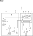
- the air conditioner 1 will be described below in terms of its configuration with reference to FIG. 1 and FIG. 2 .
- the air conditioner 1 has a function of cooling and heating air in a room R1.
- the air conditioner 1 includes an indoor unit 2 located in the room R1, an outdoor unit 3 located outdoors, a refrigerant circuit 4 provided with a refrigerant circulating therein, and a control unit 5.
- Examples of the refrigerant include R32.
- the room R1 should not be particularly limited in terms of its use, and examples thereof can include a human living space (e.g. a house, a store, an office, or a factory), a warehouse storing food materials, and a space equipped with machinery and tools (e.g. a server).
- the refrigerant circuit 4 includes a compressor 11, a switching mechanism 12, a heat source heat exchanger 13, a decompression mechanism 14, a utilization heat exchanger 15, and an accumulator 16.
- the respective devices 11 to 16 are connected such that the refrigerant discharged from the compressor 11 flows in the switching mechanism 12, the heat source heat exchanger 13, the decompression mechanism 14, the utilization heat exchanger 15, the switching mechanism 12, and the accumulator 16 in the mentioned order to return to the compressor 11.
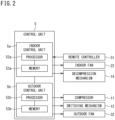
- the control unit 5 includes an indoor control unit 5a and an outdoor control unit 5b connected to each other via a communication line.
- the indoor control unit 5a includes a processor 52a and a memory 53a.
- the indoor control unit 5a controls respective parts included in the indoor unit 2.
- the outdoor control unit 5b includes a processor 52b and a memory 53b.
- the outdoor control unit 5b controls respective parts included in the outdoor unit 3.
- the outdoor unit 3 includes a case 31 provided with an intake port (not depicted) and an exhaust air port (not depicted).
- the case 31 accommodates the compressor 11, the switching mechanism 12, the heat source heat exchanger 13, and the accumulator 16 in the refrigerant circuit 4.
- the case 31 further accommodates the outdoor control unit 5b and an outdoor fan 32.
- the compressor 11 is exemplarily of a variable capacity type, and has a rotation frequency controlled by an inverter in accordance with a behavior command from the control unit 5.
- the switching mechanism 12 is configured to switch a flow direction of the refrigerant in the refrigerant circuit 4, and is exemplarily constituted by a four-way switching valve.
- the switching mechanism 12 is controlled by the control unit 5 so as to be switched between a first connection state (solid lines in FIG. 1 ) where the refrigerant discharged from the compressor 11 is sent to the heat source heat exchanger 13 and a second connection state (broken lines in FIG. 1 ) where the refrigerant discharged from the compressor 11 is sent to the utilization heat exchanger 15.
- the heat source heat exchanger 13 is exemplarily of a cross-fin tube type.
- the accumulator 16 is configured to separate the refrigerant into a gas refrigerant and a liquid refrigerant in order to protect the compressor 11.
- Examples of the outdoor fan 32 include a propeller fan. When the outdoor fan 32 operates, outdoor air is sucked via the intake port (not depicted) of the case 31, and air having exchanged heat with the refrigerant in the heat source heat exchanger 13 is discharged to an outdoor space via the exhaust air port (not depicted) of the case 31.
- the indoor unit 2 includes a case 21 provided with intake ports 26a and 26b ( FIG. 3 ) and a blow-out port 26c ( FIG. 3 ).
- the case 21 accommodates the decompression mechanism 14 and the utilization heat exchanger 15 in the refrigerant circuit 4.
- the case 21 further accommodates the indoor control unit 5a and an indoor fan 22.
- the decompression mechanism 14 is exemplarily constituted by an electromagnetic valve (expansion valve), and controls pressure and a flow rate of the refrigerant flowing in the refrigerant circuit 4.
- the decompression mechanism 14 may be accommodated in the case 31 of the outdoor unit 3.
- the utilization heat exchanger 15 is exemplarily of a cross-fin tube type.
- Examples of the indoor fan 22 include a cross-flow fan.
- the indoor fan 22 operates, air in the room R1 is sucked via the intake ports 26a and 26b of the case 21, and conditioned air having exchanged heat with the refrigerant in the utilization heat exchanger 15 is supplied into the room R1 via the blow-out port 26c of the case 21.
- the indoor unit 2 is provided with a remote control unit 51 (hereinafter, called a "remote controller 51").
- the remote controller 51 is located in the room R1 in a state of being communicable wiredly or wirelessly with the indoor control unit 5a, and transmits a control signal to the indoor control unit 5a in accordance with user operation.
- the control unit 5 causes the air conditioner 1 to execute cooling operation or heating operation in accordance with a command received by the remote controller 51.
- the control unit 5 brings the switching mechanism 12 into the first connection state (the solid lines in FIG. 1 ).
- the control unit 5 operates the compressor 11 in this state to achieves a refrigeration cycle in which the heat source heat exchanger 13 functions as a condenser and the utilization heat exchanger 15 functions as an evaporator.
- the compressor 11 discharges a high-pressure refrigerant that passes the switching mechanism 12, enters the heat source heat exchanger 13, and exchanges heat with outdoor air to be condensed.
- the refrigerant thus condensed is decompressed while passing the decompression mechanism 14, and then enters the utilization heat exchanger 15 to exchange heat with air in the room R1 and be evaporated.
- the indoor fan 22 causes conditioned air cooled by the refrigerant to blow into the room R1.
- the refrigerant having exited the utilization heat exchanger 15 passes the switching mechanism 12 and enters the accumulator 16, to be separated into gas and liquid and be then sucked into the compressor 11.
- the control unit 5 controls an opening degree of the decompression mechanism 14 during cooling operation. More specifically, when the utilization heat exchanger 15 functions as an evaporator, the control unit 5 controls the opening degree of the decompression mechanism 14 such that the refrigerant flowing out of a heat transfer tube 6 to be described later and serve as an outlet of the refrigerant in the utilization heat exchanger 15 has a dryness degree that is equal to or more than a predetermined value (e.g. equal to or more than 95%).
- a predetermined value e.g. equal to or more than 95%).
- the control unit 5 controls the dryness degree to further reduce liquid volume of the refrigerant flowing out of the outlet of the utilization heat exchanger 15 toward the outdoor unit 3, so as to inhibit suction, into the compressor 11, of the refrigerant in an excessively damp state. Meanwhile, such control lowers cooling capacity in the heat transfer tube 6 serving as a refrigerant outlet. Accordingly, air passing the utilization heat exchanger 15 may not be cooled sufficiently depending on a position of a tube removed region (a second region B1, B2, or B3) to be described later.
- a heat transfer tube region (a first region A1, A2, or A3) to be described later and the tube removed region (the second region B1, B2, or B3) are inventively disposed such that air passing the utilization heat exchanger 15 is cooled sufficiently, so as to achieve an object relevant to the control described above.
- control unit 5 brings the switching mechanism 12 into the second connection state (the broken lines in FIG. 1 ).
- the control unit 5 operates the compressor 11 in this state to achieves a refrigeration cycle in which the heat source heat exchanger 13 functions as an evaporator and the utilization heat exchanger 15 functions as a condenser.
- the compressor 11 discharges a high-pressure refrigerant that passes the switching mechanism 12, enters the utilization heat exchanger 15, and exchanges heat with air in the room R1 to be condensed.
- the indoor fan 22 causes conditioned air heated by the refrigerant to blow into the room R1.
- the refrigerant thus condensed is decompressed while passing the decompression mechanism 14, and then enters the heat source heat exchanger 13 to exchange heat with outdoor air and be evaporated.
- the refrigerant having exited the heat source heat exchanger 13 passes the switching mechanism 12 and enters the accumulator 16, to be separated into gas and liquid and be then sucked into the compressor 11.
- FIG. 3 is a pattern view depicting an internal structure of the indoor unit 2 according to the embodiment.
- FIG. 3 includes hatched portions depicted as sections.
- the indoor unit 2 according to the present embodiment is of a wall mounted type, and is located on an upper portion of a side wall of the room R1 or the like.
- an indoor end of the side wall provided with the indoor unit 2 will correspond to a "front end” of the indoor unit 2, and an end opposite to the front end will correspond to a "rear end” of the indoor unit 2, where appropriate.
- a left end in FIG. 3 corresponds to the "front end” and a right end in FIG. 3 corresponds to the "rear end”.
- a perpendicularly upper end corresponds to an "upper end” of the indoor unit 2, and also corresponds to an upper end in FIG. 3 .
- a perpendicularly lower end corresponds to a "lower end" of the indoor unit 2, and also corresponds to a lower end in FIG. 3 .
- a direction orthogonal to an anteroposterior direction and a vertical direction corresponds to a transverse direction.
- a "right end” of the indoor unit 2 corresponds to a far end of a sheet of FIG. 3
- a "left end” of the indoor unit 2 corresponds to a near end of the sheet of FIG. 3 .
- the utilization heat exchanger 15 includes a heat exchanger 15a located in front of the indoor fan 22, and a heat exchanger 15b located behind the indoor fan 22.
- the case 21 includes a front panel 21a, a top panel 21b, a back panel 21c, a first accommodation panel 21d, a second accommodation panel 21e, and a flow path bottom plate 21f.
- the front panel 21a is a plate-shaped member covering front ends of the utilization heat exchanger 15 and the indoor fan 22.
- the front panel 21a is provided with a front intake port 26a.
- the top panel 21b is a plate-shaped member covering upper ends of the utilization heat exchanger 15 and the indoor fan 22.
- the top panel 21b is equipped with a grill 23 that is provided with the top intake port 26b.
- Each of the front intake port 26a and the top intake port 26b may also be called an "intake port”.
- the back panel 21c is a plate-shaped member covering rear ends of the utilization heat exchanger 15 and the indoor fan 22.
- the first accommodation panel 21d is a plate-shaped member accommodating the heat exchanger 15a from below.
- the first accommodation panel 21d and the heat exchanger 15a interpose a drain pan 24a.
- the drain pan 24a is a gutter-shaped member configured to collect condensate generated in the heat exchanger 15a.
- the second accommodation panel 21e is a plate-shaped member accommodating the heat exchanger 15b from below.
- the second accommodation panel 21e and the heat exchanger 15b interpose a drain pan 24b.
- the drain pan 24b is a gutter-shaped member configured to collect condensate generated in the heat exchanger 15b.
- the flow path bottom plate 21f is a plate-shaped member extending obliquely forward and downward from behind the indoor fan 22.
- a lower surface of the first accommodation panel 21d an upper surface of the flow path bottom plate 21f form a flow path of air blowing out of the indoor fan 22.
- the flow path has an outlet serving as the blow-out port 26c of the case 21.
- the case 21 is provided with a flap 25.
- the flap 25 is adjusted in terms of its inclination angle to shut off or open the blow-out port 26c.
- the inclination angle of the flap 25 also leads to adjustment of a blow-out direction of conditioned air.
- FIG. 3 exemplarily depicts the indoor unit 2 including two flaps 25, although the indoor unit 2 should not be limited in terms of the number of the flaps 25.
- the indoor fan 22 rotates to exemplarily generate air flows F1 to F4.
- the air flow F1 flows out of the front intake port 26a, passes the heat exchanger 15a, and flows toward the indoor fan 22.
- the air flow F2 flows out of the top intake port 26b, passes the heat exchanger 15a, and flows toward the indoor fan 22.
- the air flow F3 flows out of the top intake port 26b, passes the heat exchanger 15b, and flows toward the indoor fan 22.
- the air flow F4 flows out of the indoor fan 22, passes the blow-out port 26c, and is sent indoors.
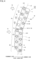
- FIG. 4 is an enlarged pattern view of the heat exchanger 15a depicted in FIG. 3 .
- the heat exchanger 15a is of a so-called fin-and-tube type, and includes a heat transfer tube 6 and a fin 7.
- the heat transfer tube 6 is a metal pipe allowing the refrigerant to flow therethrough.
- the fin 7 is a plate-shaped member having a thickness direction matching the transverse direction, and is exemplarily made of an aluminum metal plate. There is provided a plurality of fins 7 stacked in the transverse direction at predetermined pitches.
- first direction a direction of air flowing from a windward side to a leeward side
- second direction a direction crossing the first direction
- the second direction is more specifically orthogonal to the first direction.
- the first direction is dependent on an air flow direction, so that each of the fins 7 may have regions different in first direction.
- the first direction corresponds to a direction from front to behind (from left to right in FIG. 4 ).
- the first direction corresponds to an obliquely backward and downward direction from front (obliquely rightward and downward from left in FIG. 4 ).
- the fin 7 has a narrow portion 7a having a smaller width than an average width in the first direction.
- the narrow portion 7a is provided in a vertically center portion of the fin 7.
- a region below the narrow portion 7a will be called a fin lower portion P1
- a region above the narrow portion 7a will be called a fin upper portion P2.
- the narrow portion 7a is a bent portion where the fin 7 is bent in the first direction.
- the fin upper portion P2 is inclined leeward from the fin lower portion P1.
- the fin lower portion P1 has a center line L1 in the first direction, and the center line L1 extends substantially along the vertical direction.
- the center line L1 extends in a direction that matches a longitudinal direction of the fin lower portion P1 and corresponds to the second direction in the fin lower portion P1.
- the fin upper portion P2 has a center line L2 in the first direction, and the center line L2 extends obliquely downward and forward from above.
- the center line L2 extends in a direction that matches a longitudinal direction of the fin upper portion P2 and corresponds to the second direction in the fin upper portion P2.
- the fin 7 is provided with a plurality of through holes 70 allowing penetration by the heat transfer tube 6.
- FIG. 4 exemplarily depicts the fin 7 provided with 16 through holes 70, although the through holes 70 should not be particularly limited in terms of the number.
- the fin 7 has an inner circumferential portion provided with the plurality of through holes 70, and the inner circumferential portion may be provided with a collar fixing the heat transfer tube 6 penetrating the through hole 70.
- the plurality of through holes 70 forms a plurality of columns in the second direction.
- FIG. 4 exemplarily depicts the plurality of through holes 70 aligned in two columns, namely, in a windward column and a leeward column each constituted by eight through holes.
- the plurality of through holes 70 included in the windward column is disposed to be staggered with respect to the plurality of through holes 70 included in the leeward column.
- the through holes disposed in this manner allows air passing the heat exchanger 15a to be evenly cooled.
- the plurality of through holes 70 included in the windward column has centers not overlapped in the first direction with centers of the plurality of through holes 70 included in the leeward column.
- a virtual line C1 which passes a center of an appropriate one of the through holes 70 in the windward column and extends in the first direction, passes between two through holes 70 and 70 included in the leeward column (more specifically, a midpoint of a line segment connecting centers of the two through holes 70 and 70).
- a virtual line C2 which passes an appropriate one of the through holes 70 in the leeward column and extends in the first direction, passes between two through holes 70 and 70 included in the windward column. In this manner, the through holes 70 in the windward column and the leeward column are alternately disposed.
- the plurality of through holes 70 includes a first through hole 71 penetrated by the heat transfer tube 6 and a second through hole 72 not penetrated by any heat transfer tube 6.
- FIG. 4 exemplifies a case where eight through holes 70 included in the fin lower portion P1 each correspond to the first through hole 71.
- Eight through holes 70 included in the fin upper portion P2 include six first through holes 71 and two second through holes 72.
- the fin 7 includes the first region A1 where a plurality of first through holes 71 is aligned in the second direction, and the second region B1 where a plurality of (two exemplarily depicted in FIG. 4 ) second through holes 72 is aligned in the second direction.
- FIG. 4 exemplarily depicts four regions A11 to A14 each corresponding to the first region A1.
- the region A11 is located in a windward upper portion of the fin upper portion P2 and includes two aligned first through holes 71.
- the region A12 is located in a leeward portion of the fin upper portion P2 and includes four aligned first through holes 71.
- the region A13 is located in a windward portion of the fin lower portion P1 and includes four aligned first through holes 71.
- the region A14 is located in a leeward portion of the fin lower portion P1 and includes four aligned first through holes 71.
- the second region B1 has an opened windward side and is surrounded with the first region A1. More specifically, the second region B1 has a leeward side adjacent to the first region A1 (the region A12) and respective ends in the second direction adjacent to the first region A1 (the regions A11 and A13).
- FIG. 5 is an enlarged pattern view of the heat exchanger 15b depicted in FIG. 3 .
- the heat exchanger 15b includes portions that are configured similarly to the heat exchanger 15a, are denoted by identical reference signs, and will not be described repeatedly.
- the heat exchanger 15b includes a heat transfer tube 6 and a fin 7.
- the fin 7 in the heat exchanger 15b has a center line L3 in the first direction, and the center line L3 extends in the second direction.
- the fin 7 is provided with the plurality of through holes 70.
- FIG. 5 exemplarily depicts the plurality of through holes 70 aligned in two columns, namely, in a windward column and a leeward column each constituted by six through holes.
- the plurality of through holes 70 in the heat exchanger 15b includes a first through hole 71 and a second through hole 72.
- FIG. 5 exemplifies a case where six through holes 70 included in the windward column each correspond to the first through hole 71. Furthermore, in the leeward column, two upper and two lower through holes 70 each correspond to the first through hole 71, and two central through holes 70 each correspond to the second through hole 72.
- the fin 7 of the heat exchanger 15b includes the first region A2 where a plurality of first through holes 71 is aligned in the second direction, and the second region B2 where a plurality of second through holes 72 is aligned in the second direction.
- FIG. 5 exemplarily depicts three regions A21 to A23 each corresponding to the first region A2.
- the region A21 is located in a leeward upper portion of the fin 7 and includes two aligned first through holes 71.
- the region A22 is located in a leeward lower portion of the fin 7 and includes two aligned first through holes 71.
- the region A23 is located in a windward portion of the fin 7 and includes six aligned first through holes 71.
- the second region B2 has an opened leeward side and is surrounded with the first region A2. More specifically, the second region B2 has a windward side adjacent to the first region A2 (the region A23) and respective ends in the second direction adjacent to the first region A2 (the regions A21 and A22).
- FIG. 6 is a pattern view of a heat exchanger 15c according to a comparative example and peripheral structures thereof.
- the heat exchanger 15c exemplifies a case different from the heat exchanger 15b ( FIG. 5 ) in terms of disposition of the first through holes 71 and the second through holes 72.
- FIG. 6 depicts configurations that are similar to those according to the embodiment, are denoted by identical reference signs, and will not be described repeatedly. The object to be achieved by the present disclosure will be described in more detail with reference to FIG. 6 .
- the heat exchanger 15c according to the comparative example includes a reduced number of heat transfer tubes 6 penetrating the through holes 70 in order to reduce production cost (such a process of reducing the number will be called tube removal).
- the fin 7 according to the comparative example thus includes first regions A91 and A92 (i.e. heat transfer tube regions), and a second region B9 (i.e. tube removed region).
- the heat exchanger 15c functions as an evaporator
- air moisture is typically condensed on the fin 7 to remove moisture from air passing the heat exchanger 15c.
- the moisture condensed on the fin 7 is collected on the drain pan 24b. This allows to dry air flowing leeward from the heat exchanger 15c so as to inhibit dew condensation on a member (e.g. the indoor fan 22) positioned leeward of the heat exchanger 15c.
- moisture may not be sufficiently removed from air passing the heat exchanger 15c in a case where the heat exchanger 15c includes the second region B9.
- Air passing the second region B9 is not cooled sufficiently in comparison to air passing the first region A91 or A92 provided with the heat transfer tube 6. Accordingly, moisture is not sufficiently removed from air having mainly passed the second region B9 and almost having failed to pass the first region A91 or A92, and relatively wet air flowing leeward may cause dew condensation on a member positioned leeward.
- the first region A91 is disposed leeward of the second region B9.
- an air flow F91 linearly passing across width of the fin 7 passes the second region B9 and then passes the first region A91 so as to achieve removal of moisture from the air flow F91.
- the air flow F91 is called a "laminar flow", a “main flow”, or the like, and passes from the intake port 26b toward the indoor fan 22 linearly and stably (i.e. in a relatively short distance).
- the "first direction" indicates such a direction of the main flow.
- the fin 7 has a lower end that has a slow air flow due to the second accommodation panel 21e and the drain pan 24b and is likely to cause turning air.
- the lower end of the fin 7 may thus have an air flow F92 passing from the intake port 26b toward the indoor fan 22 while largely detouring around the lower end of the fin 7.
- the air flow F92 is called a "turbulent flow", a "bypass flow”, or the like, and passes obliquely with respect to the air flow F91 (in the first direction).
- FIG. 6 exemplifies a case where the air flow F92 passes the second region B9 at the lower end of the fin 7 and then reaching the indoor fan 22 while almost failing to pass the first region A91. Accordingly, moisture cannot be sufficiently removed from the air flow F92.
- the second region B9 is provided at an end (upper end or lower end) in the second direction of the fin 7, the air flow F92 flowing obliquely with respect to the main flow cannot have sufficient moisture removal, and moisture contained in the air flow F92 may cause dew condensation on a member positioned leeward of the heat exchanger 15c.
- the second region B1 or B2 (tube removed region) is surrounded with the first region A1 or A2 (heat transfer tube region) with the windward side or the leeward side being opened. That is, the first region A1 or A2 is positioned adjacent to the respective ends (an upper end and a lower end) in the second direction of the second region B 1 or B2, and the first region A1 or A2 is positioned also windward or leeward of the second region B1 or B2.
- Such a configuration allows the first region A1 or A2 to more reliably cool air having passed (or being subject to pass) the second region B1 or B2.
- the heat exchanger 15a or 15b can thus have more reliable dew condensation to sufficiently dry air flowing leeward from the heat exchanger 15a or 15b, for inhibition of dew condensation on a member positioned leeward of the heat exchanger 15a or 15b.
- the first region A1 or A2 adjacent in the first direction to the second region B1 or B2 has respective ends in the second direction positioned outside respective ends in the second direction of the second region B1 or B2.
- the first region A1 (the region A12 or A14) provided adjacent to a leeward side of the second region B1 has an upper end in the second direction positioned above an upper end in the second direction of the second region B 1
- the first region A1 (the region A12 or A14) provided adjacent to the leeward side of the second region B1 has a lower end in the second direction positioned below a lower end in the second direction of the second region B1.
- the heat exchangers 15a and 15b will be described in terms of more characteristics with reference to FIG. 4 and FIG. 5 .
- the first through holes 71 include an outlet through hole 73 and an inlet through hole 75.
- the outlet through hole 73 corresponds to the first through hole 71 penetrated by the heat transfer tube 6 serving as a refrigerant outlet when the heat exchanger 15a or 15b functions as an evaporator.
- the outlet through hole 73 is denoted by an arrowhead sign (black point mark).
- the outlet through hole 73 is positioned adjacent in the first direction to the first region A1 or A2.
- the heat exchanger 15a or 15b functions as an evaporator
- the refrigerant flowing in the heat transfer tube 6 serving as a refrigerant outlet is mostly (or entirely) in a gas state. Accordingly, the heat transfer tube 6 serving as a refrigerant outlet has almost no room for heat absorption from air and refrigerant evaporation, failing to sufficiently cool passing air.
- the present embodiment provides the outlet through hole 73 positioned adjacent in the first direction to the first region A1 or A2, so that the adjacent first region A1 or A2 more reliably cools air not cooled sufficiently and having passed (or being subject to pass) the outlet through hole 73 and the vicinity thereof.
- the heat exchanger 15a or 15b can thus have more reliable dew condensation to inhibit dew condensation on a member positioned leeward of the heat exchanger 15a or 15b.
- the outlet through hole 73 in the region A11 is disposed adjacent to a windward side of the region A12, and the outlet through hole 73 in the region A13 is disposed adjacent to a windward side of the region A14. If the heat transfer tube 6 having low cooling capacity is provided windward and the heat transfer tube 6 having high cooling capacity (the heat transfer tube 6 other than the heat transfer tube 6 serving as a refrigerant outlet) is provided leeward, passing air is gradually cooled to achieve higher cooling efficiency in comparison to a case of disposition in an inverted order.
- the outlet through hole 73 is penetrated by the heat transfer tube 6 having low cooling capacity, and is thus provided windward of a different one of the first regions A1 for enhanced air cooling efficiency.
- the inlet through hole 75 corresponds to the first through hole 71 penetrated by the heat transfer tube 6 serving as a refrigerant inlet when the heat exchanger 15a or 15b functions as an evaporator.
- the inlet through hole 75 is denoted by an arrow feather sign ("X" mark).
- the inlet through hole 75 is provided in a region having air flow speed of air passing the heat exchanger 15a or 15b higher than average air flow speed, and in the leeward column.
- FIG. 4 depicts, as a region D1, a region mainly receiving the air flow F1 or F2 and having air flow speed higher than the average air flow speed.
- FIG. 4 further depicts, as a region D2, a region having a flow blocked by the first accommodation panel 21d or the like and air flow speed lower than the average air flow speed.
- the inlet through hole 75 in the region A12 is included in the region D1.
- the refrigerant flowing in the heat transfer tube 6 serving as a refrigerant inlet is mostly (or entirely) in a liquid state. Accordingly, the heat transfer tube 6 serving as a refrigerant inlet is likely to allow the refrigerant to absorb heat from air and evaporate, for preferable cooling of passing air.
- the inlet through hole 75 thus corresponds to a region most likely to be cooled when the heat exchanger 15a or 15b functions as an evaporator.
- the inlet through hole 75 is provided in the region having air flow speed higher than the average air flow speed (i.e. a region having large air flow volume) to achieve enhanced air cooling efficiency.
- the inlet through hole 75 is provided in the leeward column to gradually cool passing air, for further enhanced air cooling efficiency.
- the inlet through hole 75 is positioned adjacent in the first direction or the second direction to the second region B1 or B2, so as to more reliably cool air passing the second through hole 72 and the vicinity thereof.
- FIG. 4 exemplifies the inlet through hole 75 included in the region A12 is adjacent to the second region B1 in the first direction.
- FIG. 5 exemplifies the inlet through hole 75 included in the region A21 is adjacent to the second region B2 in the second direction.
- the plurality of through holes 70 includes a narrow portion through hole 74 that is provided closest to the narrow portion 7a and corresponds to the first through hole 71.
- the narrow portion 7a has narrow width and is thus lower in cooling capacity than the remaining portion of the fin 7.
- the narrow portion through hole 74 corresponds to the inlet through hole 75 as depicted in FIG. 4 .
- the inlet through hole 75 corresponds to the region most likely to be cooled when the heat exchanger 15a or 15b functions as an evaporator.
- the inlet through hole 75 is provided in the narrow portion 7a having low cooling capacity to compensate such low cooling capacity in the narrow portion 7a. This enables more reliable cooling of air passing the narrow portion 7a.
- the narrow portion through hole 74 is positioned adjacent to the leeward side of the second region B1.
- the narrow portion through hole 74 corresponds to the inlet through hole 75, so as to preferably cool air passing the narrow portion through hole 74 and the vicinity thereof. Accordingly, the narrow portion through hole 74 is positioned adjacent to the leeward side of the second region B1, so that the heat transfer tube 6 penetrating the narrow portion through hole 74 more reliably cools air having passed the second region B1 and the vicinity thereof and not cooled sufficiently.
- FIG. 4 depicts the narrow portion through hole 74 positioned leeward of the second region B1.
- the narrow portion through hole 74 may alternatively be positioned windward of the second region B1. That is, the narrow portion through hole 74 corresponding to the inlet through hole 75 has only to be positioned adjacent to the second region B1 in the first direction.
- FIG. 7 is a pattern view depicting an internal structure of an indoor unit 2a according to a modification example.
- the indoor unit 2a is of a ceiling embedded type, and is embedded in a ceiling of the room R1 ( FIG. 1 ) or the like.
- the indoor unit according to the present disclosure should not be limited in terms of a locating manner in the room R1, and may correspond to the indoor unit 2 of the wall mounted type as in FIG. 3 , the indoor unit 2a of the ceiling embedded type as in FIG. 7 , or an indoor unit (not depicted) of a ceiling pendent type or a floorstanding type.
- the indoor unit 2a includes the case 21, and the indoor fan 22 and a heat exchanger 15d accommodated in the case 21.
- the heat exchanger 15d functions as the utilization heat exchanger 15 in the air conditioner 1 ( FIG. 1 ).
- An air flow F5 blowing out of the indoor fan 22 passes the heat exchanger 15d.
- the heat exchanger 15d includes the heat transfer tube 6 and a fin 7b.
- the fin 7b is provided with through holes 70 in three columns with respect to the first direction in which the air flow F5 passes. That is, the through holes 70 are provided in the three columns in the second direction crossing the first direction (a direction crossing the air flow F5).
- the through holes 70 in the fin 7b should not be limited in terms of the number of columns, and may alternatively be provided in the three columns with respect to the first direction, or in four or more columns with respect to the first direction.
- the plurality of through holes 70 includes a first through hole 71 penetrated by the heat transfer tube 6 and a second through hole 72 not penetrated by any heat transfer tube 6. That is, the heat transfer tubes 6 are removed from some of the plurality of through holes 70.
- ten through holes 70 positioned in the most windward column each correspond to the first through hole 71
- ten through holes 70 positioned in the most leeward column each correspond to the second through hole 72.
- four through holes from an upper end each correspond to the first through hole 71
- next two through holes each correspond to the second through hole 72
- subsequent two through holes each correspond to the first through hole 71
- remaining two through holes each correspond to the second through hole 72.
- the second region B3 including the second through holes 72 aligned in the second direction is surrounded with the first region A3 including the first through holes 71 aligned in the second direction. More specifically, the second region B3 has a windward side adjacent to the first region A3 (a region A32) and respective ends in the second direction adjacent to the first region A3 (regions A31 and A33). Such a configuration allows the first region A3 to more reliably cool air being subject to pass the second region B3.
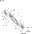
- FIG. 8 is a pattern view of a heat exchanger 15e according to a modification example.
- the heat exchanger 15e is according to a further modification example of the heat exchanger 15d ( FIG. 7 ) according to the modification example.
- the heat exchanger 15e includes the heat transfer tube 6 and a fin 7c.
- the fin 7c is provided with through holes 70 in three columns with respect to the first direction in which the air flow F5 passes.
- the plurality of through holes 70 includes the first through hole 71 and the second through hole 72.
- sixteen through holes 70 positioned in the most windward column each correspond to the first through hole 71.
- sixteen through holes 70 positioned in the middle column in the first direction two through holes from an upper end each correspond to the first through hole 71, next three through holes each correspond to the second through hole 72, subsequent two through holes each correspond to the first through hole 71, following two through holes each correspond to the second through hole 72, and remaining seven through holes each correspond to the first through hole 71.
- sixteen through holes 70 positioned in the most leeward column two through holes from an upper end each correspond to the first through hole 71, next three through holes each correspond to the second through hole 72, subsequent five through holes each correspond to the first through hole 71, following four through holes each correspond to the second through hole 72, and remaining two through holes each correspond to the first through hole 71.
- the fin 7c includes a first region A4 where a plurality of first through holes 71 is aligned in the second direction, and a second region B4 where a plurality of second through holes 72 is aligned in the second direction.
- FIG. 8 exemplarily depicts six regions A41 to A46 each corresponding to the first region A4, and three regions B41 to B43 each corresponding to the second region B4.
- the second region B4 is surrounded with the first region A4.
- FIG. 8 depicts various variations where the second region B4 is surrounded with the first region A4.
- the region B41 has an opened leeward side, a windward side adjacent to the region A42, and respective ends in the second direction adjacent to the regions A41 and A43.
- the second region B4 (the region B41) having two columns with respect to the first direction
- the second region B4 has the respective ends in the second direction adjacent to the regions A41 and A43 having two columns so as to be surrounded therewith, to allow the first region A4 to more reliably cool air being subject to pass the second region B4.
- the region B42 has a windward side adjacent to the region A42, a leeward side adjacent to the region A44, and respective ends in the second direction adjacent to the regions A43 and A45.
- the region B42 has respective ends in the first direction and respective ends in the second direction surrounded with the first region A4, so as to more reliably cool air passing the second region B4.
- the region B43 has an opened leeward side, a windward side adjacent to the region A45, and respective ends in the second direction adjacent to the regions A44 and A46.
- the first region A4 having two columns corresponding to the regions A42 and A45 is positioned windward of the region B43, so as to more reliably cool air passing in the first direction.
- the second regions B1, B2, B3, and B4 (the tube removed regions) includes the second through holes 72 not penetrated by the heat transfer tubes 6 and aligned in the second direction. Air passing the second region B1, B2, B3, or B4 is thus not cooled sufficiently in comparison to air passing the first region A1, A2, A3, or A4 (the heat transfer tube region).
- the present disclosure provides the second regions B1, B2, B3, and B4 surrounded with the first regions A1, A2, A3, and A4 in the first direction and the second direction, so that the first region A1, A2, A3, or A4 more reliably cools air having passed (or being subject to pass) the second region B1, B2, B3, or B4.
- the heat exchanger 15a, 15b, 15d, or 15e can thus have more reliable dew condensation to inhibit dew condensation on a member positioned leeward of the heat exchanger 15a, 15b, 15d, or 15e.
- the first through holes 71 includes the outlet through hole 73 penetrated by the heat transfer tube 6 serving as the refrigerant outlet when the heat exchanger 15a, 15b functions as the evaporator, and the outlet through hole 73 is positioned adjacent in the first direction to the first region A1, A2.
- the heat exchanger 15a or 15b When the heat exchanger 15a or 15b functions as an evaporator, the refrigerant flowing in the heat transfer tube 6 serving as a refrigerant outlet is mostly (or entirely) in a gas state. Accordingly, the heat transfer tube 6 has almost no room for heat absorption from air and refrigerant evaporation, failing to sufficiently cool passing air.
- the outlet through hole 73 penetrated by the heat transfer tube 6 is positioned adjacent in the first direction to the first region A1 or A2, so that the adjacent first region A1 or A2 more reliably cools air not cooled sufficiently and having passed (or being subject to pass) the outlet through hole 73 and the vicinity thereof.
- the heat exchanger 15a or 15b can thus have more reliable dew condensation to inhibit dew condensation on a member positioned leeward of the heat exchanger 15a or 15b.
- the outlet through hole 73 is positioned adjacent to the windward side of the first region A1.
- the heat transfer tube 6 having low cooling capacity is provided windward and the heat transfer tube 6 having high cooling capacity is provided leeward, passing air is gradually cooled to achieve higher cooling efficiency in comparison to a case of disposition in an inverted order.
- the outlet through hole 73 is penetrated by the heat transfer tube 6 having low cooling capacity, and is thus provided windward of a different one of the first regions A1 for enhanced air cooling efficiency.
- the plurality of through holes 70 included in the column on the windward side is disposed to be staggered with respect to the plurality of through holes 70 included in the column on the leeward side.
- the plurality of through holes 70 disposed to be staggered allows passing air to be evenly cooled.
- the fin 7 includes the narrow portion 7a having the smaller width than the average width in the first direction
- the plurality of through holes 70 includes the narrow portion through hole 74 provided closest to the narrow portion 7a and corresponding to the first through hole 71.
- the narrow portion 7a is lower in cooling capacity than the remaining portion of the fin 7.
- the narrow portion through hole 74 provided closest to the narrow portion 7a corresponds to the first through hole 71 (the through hole 70 penetrated by the heat transfer tube 6)
- air passing such a portion can be cooled more reliably.
- the narrow portion 7a is the bent portion where the fin 7 is bent in the first direction.
- the first through holes 71 include the inlet through hole 75 penetrated by the heat transfer tube 6 serving as the refrigerant inlet when the heat exchanger 15a functions as the evaporator, and the narrow portion through hole 74 corresponds to the inlet through hole 75.
- the refrigerant flowing in the heat transfer tube 6 serving as a refrigerant inlet is mostly (or entirely) in a liquid state. Accordingly, the heat transfer tube 6 is likely to allow the refrigerant to absorb heat from air and evaporate, for preferable cooling of passing air.
- the inlet through hole 75 penetrated by the heat transfer tube 6 is provided in the narrow portion 7a having low cooling capacity to compensate such low cooling capacity in the narrow portion 7a. This enables more reliable cooling of air passing the narrow portion 7a.
- the narrow portion through hole 74 is positioned adjacent in the first direction to the second region B1.
- the narrow portion through hole 74 corresponds to the inlet through hole 75, so as to preferably cool air passing the narrow portion through hole 74 and the vicinity thereof. Accordingly, the narrow portion through hole 74 is positioned adjacent in the first direction to the second region B1, so that the heat transfer tube 6 penetrating the narrow portion through hole 74 more reliably cools air having passed (or being subject to pass) the second region B1 and the vicinity thereof and not cooled sufficiently.
- the first through holes 71 include the inlet through hole 75 penetrated by the heat transfer tube 6 serving as the refrigerant inlet when the heat exchanger 15a functions as the evaporator, and the inlet through hole 75 is provided in the region where air passing the heat exchanger 15 has air flow speed higher than average air flow speed, and in the column on the leeward side.
- the inlet through hole 75 penetrated by the heat transfer tube 6 serving as a refrigerant inlet and constituting a region most likely to be cooled is provided in the region having air flow speed higher than the average air flow speed (i.e. a region having large air flow volume) to achieve enhanced air cooling efficiency.
- the inlet through hole 75 is provided in the column on the leeward side to gradually cool passing air, for further enhanced air cooling efficiency.
- the embodiment provides the air conditioner 1 including the refrigerant circuit 4 including the compressor 11, the heat source heat exchanger 13, the decompression mechanism 14, and the utilization heat exchanger 15 connected in the mentioned order, in which the utilization heat exchanger 15 includes the heat exchanger 15a, 15b, 15d, 15e according to any one of claims 1 to 9.
- the air conditioner 1 further includes the control unit 5 configured to control the opening degree of the decompression mechanism 14, in which the control unit 5 controls the opening degree to cause the refrigerant flowing out of the heat transfer tube 6 serving as the refrigerant outlet when the utilization heat exchanger 15 functions as the evaporator to have the dryness degree equal to or more than the predetermined value.
- the refrigerant flowing out of the outlet is further reduced in liquid volume to inhibit suction, into the compressor 11, of the refrigerant in an excessively damp state. Meanwhile, such control lowers cooling capacity in the heat transfer tube 6 serving as a refrigerant outlet. Accordingly, passing air may not be cooled sufficiently depending on the position of the second region B 1, B2, B3, or B4.
- the utilization heat exchanger 15 included in the air conditioner 1 according to the present disclosure the first region A1, A2, A3, or A4 and the second region B1, B2, B3, or B4 are inventively disposed such that passing air is cooled sufficiently, so as to achieve an object relevant to the control described above.
Landscapes
- Engineering & Computer Science (AREA)
- Mechanical Engineering (AREA)
- General Engineering & Computer Science (AREA)
- Physics & Mathematics (AREA)
- Thermal Sciences (AREA)
- Chemical & Material Sciences (AREA)
- Combustion & Propulsion (AREA)
- Heat-Exchange Devices With Radiators And Conduit Assemblies (AREA)
- Air Filters, Heat-Exchange Apparatuses, And Housings Of Air-Conditioning Units (AREA)
Abstract
Description
- The present disclosure relates to a heat exchanger and an air conditioner.
- An air conditioner or an apparatus similar to the air conditioner includes a fin-and-tube heat exchanger. The heat exchanger of this type (hereinafter, simply called "heat exchanger") is produced by causing a plurality of heat transfer tubes to penetrate a plurality of fins.
- There have been conventionally produced in some cases a plurality of types of heat exchangers each including a commonly shaped fin and a different number of heat transfer tubes penetrating the fin, for reduction in production cost for the heat exchangers (e.g. PATENT LITERATURE 1). For example, production of a heat exchanger including a fin having collar portions (through hole portions provided in the fin) in two columns and heat transfer tubes in two columns inserted to the fin, and a heat exchanger including an identically shaped fin and heat transfer tubes in a single column inserted to the fin achieves production of different types of heat exchangers with reduced production cost for the fins or the like. In each of the heat exchangers thus produced, the collar portions of the fin may include a region (tube removed region) not provided with the heat transfer tube.
- PATENT LITERATURE 1:
Japanese Laid-Open Patent Publication No. 2015-127607 -
- (1) The present disclosure provides a heat exchanger including: a heat transfer tube allowing a refrigerant to flow; and a fin provided with a plurality of through holes each allowing penetration of the heat transfer tube in a thickness direction; in which the plurality of through holes is aligned in a plurality of columns in a second direction crossing a first direction of air flowing from a windward side toward a leeward side, and includes first through holes each penetrated by the heat transfer tube and second through holes not penetrated by the heat transfer tube, the fin includes a first region having the first through holes aligned in the second direction, and a second region having the second through holes aligned in the second direction, and the second region has an end or respective ends in the first direction adjacent to the first region, and respective ends in the second direction adjacent to the first region.
- The second region (tube removed region) includes the second through holes not penetrated by the heat transfer tube and aligned in the second direction. Air passing the second region is thus not cooled sufficiently in comparison to air passing the first region (heat transfer tube region). The present disclosure provides the second region surrounded with the first region in the first direction and the second direction, so that the first region more reliably cools air having passed (or being subject to pass) the second region. The heat exchanger can thus have more reliable dew condensation to inhibit dew condensation on a member positioned leeward of the heat exchanger.
- (2) Preferably, the first through holes includes an outlet through hole penetrated by the heat transfer tube serving as a refrigerant outlet when the heat exchanger functions as an evaporator, and the outlet through hole is positioned adjacent in the first direction to the first region.
- When the heat exchanger functions as an evaporator, the refrigerant flowing in the heat transfer tube serving as a refrigerant outlet is mostly (or entirely) in a gas state. Accordingly, the heat transfer tube has almost no room for heat absorption from air and refrigerant evaporation, failing to sufficiently cool passing air. The outlet through hole penetrated by the heat transfer tube is positioned adjacent in the first direction to the first region, so that the adjacent first region more reliably cools air not cooled sufficiently and having passed (or being subject to pass) the outlet through hole and the vicinity thereof. The heat exchanger can thus have more reliable dew condensation to inhibit dew condensation on a member positioned leeward of the heat exchanger.
- (3) Preferably, the outlet through hole is positioned adjacent to the windward side of the first region.
- If the heat transfer tube having low cooling capacity is provided windward and the heat transfer tube having high cooling capacity is provided leeward, passing air is gradually cooled to achieve higher cooling efficiency in comparison to a case of disposition in an inverted order. The outlet through hole is penetrated by the heat transfer tube having low cooling capacity, and is thus provided windward of a different first region for enhanced air cooling efficiency.
- (4) Preferably, in the fin, the plurality of through holes included in a column on the windward side is disposed to be staggered with respect to the plurality of through holes included in a column on the leeward side.
- The plurality of through holes disposed to be staggered allows passing air to be evenly cooled.
- (5) Preferably, the fin includes a narrow portion having a smaller width than an average width in the first direction, and the plurality of through holes includes a narrow portion through hole provided closest to the narrow portion and corresponding to the first through hole.
- The narrow portion is lower in cooling capacity than the remaining portion of the fin. When the narrow portion through hole provided closest to the narrow portion corresponds to the first through hole (the through hole penetrated by the heat transfer tube), air passing such a portion can be cooled more reliably.
- (6) Preferably, the narrow portion is a bent portion where the fin is bent in the first direction.
- (7) Preferably, the first through holes include an inlet through hole penetrated by the heat transfer tube serving as a refrigerant inlet when the heat exchanger functions as an evaporator, and the narrow portion through hole corresponds to the inlet through hole.
- When the heat exchanger functions as an evaporator, the refrigerant flowing in the heat transfer tube serving as a refrigerant inlet is mostly (or entirely) in a liquid state. Accordingly, the heat transfer tube is likely to allow the refrigerant to absorb heat from air and evaporate, for preferable cooling of passing air. The inlet through hole penetrated by the heat transfer tube is provided in the narrow portion having low cooling capacity to compensate such low cooling capacity in the narrow portion. This enables more reliable cooling of air passing the narrow portion.
- (8) Preferably, the narrow portion through hole is positioned adjacent in the first direction to the second region.
- The narrow portion through hole corresponds to the inlet through hole, so as to preferably cool air passing the narrow portion through hole and the vicinity thereof. Accordingly, the narrow portion through hole is positioned adjacent in the first direction to the second region, so that the heat transfer tube penetrating the narrow portion through hole more reliably cools air having passed (or being subject to pass) the second region and the vicinity thereof and not cooled sufficiently.
- (9) Preferably, the first through holes include an inlet through hole penetrated by the heat transfer tube serving as a refrigerant inlet when the heat exchanger functions as an evaporator, and the inlet through hole is provided in a region where air passing the heat exchanger has air flow speed higher than average air flow speed, and in a column on the leeward side.
- The inlet through hole penetrated by the heat transfer tube serving as a refrigerant inlet and constituting a region most likely to be cooled is provided in the region having air flow speed higher than the average air flow speed (i.e. a region having large air flow volume) to achieve enhanced air cooling efficiency. The inlet through hole is provided in the column on the leeward side to gradually cool passing air, for further enhanced air cooling efficiency.
- (10) The present disclosure provides an air conditioner including a refrigerant circuit including a compressor, a heat source heat exchanger, a decompression mechanism, and a utilization heat exchanger connected in a mentioned order, in which the utilization heat exchanger includes the heat exchanger according to any one of (1) to (9) described above.
- (11) Preferably, the air conditioner according to the present disclosure further includes a control unit configured to control an opening degree of the decompression mechanism, in which the control unit controls the opening degree to cause a refrigerant flowing out of the heat transfer tube serving as a refrigerant outlet when the utilization heat exchanger functions as an evaporator to have a dryness degree equal to or more than a predetermined value.
- In the air conditioner achieving such control, the refrigerant flowing out of the outlet is further reduced in liquid volume to inhibit suction, into the compressor, of the refrigerant in an excessively damp state. Meanwhile, such control lowers cooling capacity in the heat transfer tube serving as a refrigerant outlet. Accordingly, passing air may not be cooled sufficiently depending on the position of the second region. In the utilization heat exchanger included in the air conditioner according to the present disclosure, the first region and the second region are inventively disposed such that passing air is cooled sufficiently, so as to achieve an object relevant to the control described above.
-
-
FIG. 1 is a configuration diagram of an air conditioner according to an embodiment. -
FIG. 2 is a functional block diagram of the air conditioner according to the embodiment. -
FIG. 3 is a pattern view depicting an internal structure of an indoor unit according to the embodiment. -
FIG. 4 is a pattern view of a heat exchanger according to the embodiment. -
FIG. 5 is a pattern view of another heat exchanger according to the embodiment. -
FIG. 6 is a pattern view of a heat exchanger according to a comparative example and peripheral structures thereof. -
FIG. 7 is a pattern view depicting an internal structure of an indoor unit according to a modification example. -
FIG. 8 is a pattern view of a heat exchanger according to another modification example. - In a case where a heat exchanger functions as an evaporator, air moisture is typically condensed on a fin to remove moisture from air passing the heat exchanger. This inhibits dew condensation on a member (e.g. a fan) positioned leeward of the heat exchanger.
- However, moisture may not be sufficiently removed from air passing the heat exchanger in a case where the heat exchanger includes a tube removed region. Air passing the tube removed region is not cooled sufficiently in comparison to air passing a region (heat transfer tube region) provided with a heat transfer tube. Accordingly, moisture is not sufficiently removed from air having mainly passed the tube removed region and almost having failed to pass the heat transfer tube region, and dew condensation may be caused on a member positioned leeward.
- It is an object of the present disclosure to inhibit dew condensation on a member positioned leeward of a heat exchanger.
- Embodiments of the present disclosure will be described hereinafter with reference to the accompanying drawings.
-
-
FIG. 1 is a schematic configuration diagram of the air conditioner 1 according to an embodiment. -
FIG. 2 is a functional block diagram of the air conditioner 1 according to the embodiment. - The air conditioner 1 will be described below in terms of its configuration with reference to
FIG. 1 andFIG. 2 . - The air conditioner 1 has a function of cooling and heating air in a room R1. The air conditioner 1 includes an
indoor unit 2 located in the room R1, anoutdoor unit 3 located outdoors, arefrigerant circuit 4 provided with a refrigerant circulating therein, and acontrol unit 5. Examples of the refrigerant include R32. The room R1 should not be particularly limited in terms of its use, and examples thereof can include a human living space (e.g. a house, a store, an office, or a factory), a warehouse storing food materials, and a space equipped with machinery and tools (e.g. a server). - The
refrigerant circuit 4 includes acompressor 11, aswitching mechanism 12, a heatsource heat exchanger 13, adecompression mechanism 14, autilization heat exchanger 15, and anaccumulator 16. In a case where the heatsource heat exchanger 13 in therefrigerant circuit 4 functions as a condenser (i.e. in a case where the air conditioner 1 executes cooling operation), therespective devices 11 to 16 are connected such that the refrigerant discharged from thecompressor 11 flows in theswitching mechanism 12, the heatsource heat exchanger 13, thedecompression mechanism 14, theutilization heat exchanger 15, theswitching mechanism 12, and theaccumulator 16 in the mentioned order to return to thecompressor 11. - The
control unit 5 includes anindoor control unit 5a and anoutdoor control unit 5b connected to each other via a communication line. As depicted inFIG. 2 , theindoor control unit 5a includes aprocessor 52a and amemory 53a. When theprocessor 52a executes arithmetic processing and control in various manners in accordance with a program in thememory 53a, theindoor control unit 5a controls respective parts included in theindoor unit 2. Theoutdoor control unit 5b includes aprocessor 52b and amemory 53b. When theprocessor 52b executes arithmetic processing and control in various manners in accordance with a program in thememory 53b, theoutdoor control unit 5b controls respective parts included in theoutdoor unit 3. - The
outdoor unit 3 includes acase 31 provided with an intake port (not depicted) and an exhaust air port (not depicted). Thecase 31 accommodates thecompressor 11, theswitching mechanism 12, the heatsource heat exchanger 13, and theaccumulator 16 in therefrigerant circuit 4. Thecase 31 further accommodates theoutdoor control unit 5b and anoutdoor fan 32. - The
compressor 11 is exemplarily of a variable capacity type, and has a rotation frequency controlled by an inverter in accordance with a behavior command from thecontrol unit 5. - The
switching mechanism 12 is configured to switch a flow direction of the refrigerant in therefrigerant circuit 4, and is exemplarily constituted by a four-way switching valve. Theswitching mechanism 12 is controlled by thecontrol unit 5 so as to be switched between a first connection state (solid lines inFIG. 1 ) where the refrigerant discharged from thecompressor 11 is sent to the heatsource heat exchanger 13 and a second connection state (broken lines inFIG. 1 ) where the refrigerant discharged from thecompressor 11 is sent to theutilization heat exchanger 15. - The heat
source heat exchanger 13 is exemplarily of a cross-fin tube type. - The
accumulator 16 is configured to separate the refrigerant into a gas refrigerant and a liquid refrigerant in order to protect thecompressor 11. - Examples of the
outdoor fan 32 include a propeller fan. When theoutdoor fan 32 operates, outdoor air is sucked via the intake port (not depicted) of thecase 31, and air having exchanged heat with the refrigerant in the heatsource heat exchanger 13 is discharged to an outdoor space via the exhaust air port (not depicted) of thecase 31. - The
indoor unit 2 includes acase 21 provided withintake ports FIG. 3 ) and a blow-outport 26c (FIG. 3 ). Thecase 21 accommodates thedecompression mechanism 14 and theutilization heat exchanger 15 in therefrigerant circuit 4. Thecase 21 further accommodates theindoor control unit 5a and anindoor fan 22. - The
decompression mechanism 14 is exemplarily constituted by an electromagnetic valve (expansion valve), and controls pressure and a flow rate of the refrigerant flowing in therefrigerant circuit 4. Thedecompression mechanism 14 may be accommodated in thecase 31 of theoutdoor unit 3. Theutilization heat exchanger 15 is exemplarily of a cross-fin tube type. - Examples of the
indoor fan 22 include a cross-flow fan. When theindoor fan 22 operates, air in the room R1 is sucked via theintake ports case 21, and conditioned air having exchanged heat with the refrigerant in theutilization heat exchanger 15 is supplied into the room R1 via the blow-outport 26c of thecase 21. - The
indoor unit 2 is provided with a remote control unit 51 (hereinafter, called a "remote controller 51"). Theremote controller 51 is located in the room R1 in a state of being communicable wiredly or wirelessly with theindoor control unit 5a, and transmits a control signal to theindoor control unit 5a in accordance with user operation. - The
control unit 5 causes the air conditioner 1 to execute cooling operation or heating operation in accordance with a command received by theremote controller 51. During cooling operation, thecontrol unit 5 brings theswitching mechanism 12 into the first connection state (the solid lines inFIG. 1 ). Thecontrol unit 5 operates thecompressor 11 in this state to achieves a refrigeration cycle in which the heatsource heat exchanger 13 functions as a condenser and theutilization heat exchanger 15 functions as an evaporator. - In this cycle, the
compressor 11 discharges a high-pressure refrigerant that passes theswitching mechanism 12, enters the heatsource heat exchanger 13, and exchanges heat with outdoor air to be condensed. The refrigerant thus condensed is decompressed while passing thedecompression mechanism 14, and then enters theutilization heat exchanger 15 to exchange heat with air in the room R1 and be evaporated. Theindoor fan 22 causes conditioned air cooled by the refrigerant to blow into the room R1. The refrigerant having exited theutilization heat exchanger 15 passes theswitching mechanism 12 and enters theaccumulator 16, to be separated into gas and liquid and be then sucked into thecompressor 11. - The
control unit 5 controls an opening degree of thedecompression mechanism 14 during cooling operation. More specifically, when theutilization heat exchanger 15 functions as an evaporator, thecontrol unit 5 controls the opening degree of thedecompression mechanism 14 such that the refrigerant flowing out of aheat transfer tube 6 to be described later and serve as an outlet of the refrigerant in theutilization heat exchanger 15 has a dryness degree that is equal to or more than a predetermined value (e.g. equal to or more than 95%). - The
control unit 5 controls the dryness degree to further reduce liquid volume of the refrigerant flowing out of the outlet of theutilization heat exchanger 15 toward theoutdoor unit 3, so as to inhibit suction, into thecompressor 11, of the refrigerant in an excessively damp state. Meanwhile, such control lowers cooling capacity in theheat transfer tube 6 serving as a refrigerant outlet. Accordingly, air passing theutilization heat exchanger 15 may not be cooled sufficiently depending on a position of a tube removed region (a second region B1, B2, or B3) to be described later. In the air conditioner 1 according to the present disclosure, a heat transfer tube region (a first region A1, A2, or A3) to be described later and the tube removed region (the second region B1, B2, or B3) are inventively disposed such that air passing theutilization heat exchanger 15 is cooled sufficiently, so as to achieve an object relevant to the control described above. - During heating operation, the
control unit 5 brings theswitching mechanism 12 into the second connection state (the broken lines inFIG. 1 ). Thecontrol unit 5 operates thecompressor 11 in this state to achieves a refrigeration cycle in which the heatsource heat exchanger 13 functions as an evaporator and theutilization heat exchanger 15 functions as a condenser. - In this cycle, the
compressor 11 discharges a high-pressure refrigerant that passes theswitching mechanism 12, enters theutilization heat exchanger 15, and exchanges heat with air in the room R1 to be condensed. Theindoor fan 22 causes conditioned air heated by the refrigerant to blow into the room R1. The refrigerant thus condensed is decompressed while passing thedecompression mechanism 14, and then enters the heatsource heat exchanger 13 to exchange heat with outdoor air and be evaporated. The refrigerant having exited the heatsource heat exchanger 13 passes theswitching mechanism 12 and enters theaccumulator 16, to be separated into gas and liquid and be then sucked into thecompressor 11. -
FIG. 3 is a pattern view depicting an internal structure of theindoor unit 2 according to the embodiment.FIG. 3 includes hatched portions depicted as sections. Theindoor unit 2 according to the present embodiment is of a wall mounted type, and is located on an upper portion of a side wall of the room R1 or the like. - In the following description, an indoor end of the side wall provided with the
indoor unit 2 will correspond to a "front end" of theindoor unit 2, and an end opposite to the front end will correspond to a "rear end" of theindoor unit 2, where appropriate. A left end inFIG. 3 corresponds to the "front end" and a right end inFIG. 3 corresponds to the "rear end". Furthermore, a perpendicularly upper end corresponds to an "upper end" of theindoor unit 2, and also corresponds to an upper end inFIG. 3 . A perpendicularly lower end corresponds to a "lower end" of theindoor unit 2, and also corresponds to a lower end inFIG. 3 . A direction orthogonal to an anteroposterior direction and a vertical direction corresponds to a transverse direction. A "right end" of theindoor unit 2 corresponds to a far end of a sheet ofFIG. 3 , and a "left end" of theindoor unit 2 corresponds to a near end of the sheet ofFIG. 3 . - The
utilization heat exchanger 15 includes aheat exchanger 15a located in front of theindoor fan 22, and aheat exchanger 15b located behind theindoor fan 22. - The
case 21 includes afront panel 21a, atop panel 21b, aback panel 21c, afirst accommodation panel 21d, asecond accommodation panel 21e, and a flow pathbottom plate 21f. Thefront panel 21a is a plate-shaped member covering front ends of theutilization heat exchanger 15 and theindoor fan 22. Thefront panel 21a is provided with afront intake port 26a. - The
top panel 21b is a plate-shaped member covering upper ends of theutilization heat exchanger 15 and theindoor fan 22. Thetop panel 21b is equipped with agrill 23 that is provided with thetop intake port 26b. Each of thefront intake port 26a and thetop intake port 26b may also be called an "intake port". Theback panel 21c is a plate-shaped member covering rear ends of theutilization heat exchanger 15 and theindoor fan 22. - The
first accommodation panel 21d is a plate-shaped member accommodating theheat exchanger 15a from below. Thefirst accommodation panel 21d and theheat exchanger 15a interpose adrain pan 24a. Thedrain pan 24a is a gutter-shaped member configured to collect condensate generated in theheat exchanger 15a. - The
second accommodation panel 21e is a plate-shaped member accommodating theheat exchanger 15b from below. Thesecond accommodation panel 21e and theheat exchanger 15b interpose adrain pan 24b. Thedrain pan 24b is a gutter-shaped member configured to collect condensate generated in theheat exchanger 15b. - The flow path
bottom plate 21f is a plate-shaped member extending obliquely forward and downward from behind theindoor fan 22. A lower surface of thefirst accommodation panel 21d an upper surface of the flow pathbottom plate 21f form a flow path of air blowing out of theindoor fan 22. The flow path has an outlet serving as the blow-outport 26c of thecase 21. - The
case 21 is provided with aflap 25. Theflap 25 is adjusted in terms of its inclination angle to shut off or open the blow-outport 26c. The inclination angle of theflap 25 also leads to adjustment of a blow-out direction of conditioned air.FIG. 3 exemplarily depicts theindoor unit 2 including twoflaps 25, although theindoor unit 2 should not be limited in terms of the number of theflaps 25. - In a state where the blow-out
port 26c is opened, theindoor fan 22 rotates to exemplarily generate air flows F1 to F4. The air flow F1 flows out of thefront intake port 26a, passes theheat exchanger 15a, and flows toward theindoor fan 22. The air flow F2 flows out of thetop intake port 26b, passes theheat exchanger 15a, and flows toward theindoor fan 22. The air flow F3 flows out of thetop intake port 26b, passes theheat exchanger 15b, and flows toward theindoor fan 22. The air flow F4 flows out of theindoor fan 22, passes the blow-outport 26c, and is sent indoors. -
FIG. 4 is an enlarged pattern view of theheat exchanger 15a depicted inFIG. 3 . Theheat exchanger 15a is of a so-called fin-and-tube type, and includes aheat transfer tube 6 and afin 7. Theheat transfer tube 6 is a metal pipe allowing the refrigerant to flow therethrough. Thefin 7 is a plate-shaped member having a thickness direction matching the transverse direction, and is exemplarily made of an aluminum metal plate. There is provided a plurality offins 7 stacked in the transverse direction at predetermined pitches. - In the following description, a direction of air flowing from a windward side to a leeward side will be called a "first direction". Furthermore, a direction crossing the first direction will be called a "second direction". The second direction is more specifically orthogonal to the first direction. The first direction is dependent on an air flow direction, so that each of the
fins 7 may have regions different in first direction. For example, in a region of thefin 7 where the air flow F1 flows in, the first direction corresponds to a direction from front to behind (from left to right inFIG. 4 ). Furthermore, in a region of thefin 7 where the air flow F2 flows in, the first direction corresponds to an obliquely backward and downward direction from front (obliquely rightward and downward from left inFIG. 4 ). - The
fin 7 has anarrow portion 7a having a smaller width than an average width in the first direction. Thenarrow portion 7a is provided in a vertically center portion of thefin 7. In thefin 7, a region below thenarrow portion 7a will be called a fin lower portion P1, and a region above thenarrow portion 7a will be called a fin upper portion P2. Thenarrow portion 7a is a bent portion where thefin 7 is bent in the first direction. The fin upper portion P2 is inclined leeward from the fin lower portion P1. - The fin lower portion P1 has a center line L1 in the first direction, and the center line L1 extends substantially along the vertical direction. The center line L1 extends in a direction that matches a longitudinal direction of the fin lower portion P1 and corresponds to the second direction in the fin lower portion P1. The fin upper portion P2 has a center line L2 in the first direction, and the center line L2 extends obliquely downward and forward from above. The center line L2 extends in a direction that matches a longitudinal direction of the fin upper portion P2 and corresponds to the second direction in the fin upper portion P2.
- The
fin 7 is provided with a plurality of throughholes 70 allowing penetration by theheat transfer tube 6.FIG. 4 exemplarily depicts thefin 7 provided with 16 throughholes 70, although the throughholes 70 should not be particularly limited in terms of the number. Thefin 7 has an inner circumferential portion provided with the plurality of throughholes 70, and the inner circumferential portion may be provided with a collar fixing theheat transfer tube 6 penetrating the throughhole 70. - The plurality of through
holes 70 forms a plurality of columns in the second direction.FIG. 4 exemplarily depicts the plurality of throughholes 70 aligned in two columns, namely, in a windward column and a leeward column each constituted by eight through holes. The plurality of throughholes 70 included in the windward column is disposed to be staggered with respect to the plurality of throughholes 70 included in the leeward column. The through holes disposed in this manner allows air passing theheat exchanger 15a to be evenly cooled. - More specifically, the plurality of through
holes 70 included in the windward column has centers not overlapped in the first direction with centers of the plurality of throughholes 70 included in the leeward column. As exemplarily depicted inFIG. 4 , a virtual line C1, which passes a center of an appropriate one of the throughholes 70 in the windward column and extends in the first direction, passes between two throughholes holes 70 and 70). A virtual line C2, which passes an appropriate one of the throughholes 70 in the leeward column and extends in the first direction, passes between two throughholes holes 70 in the windward column and the leeward column are alternately disposed. - The plurality of through
holes 70 includes a first throughhole 71 penetrated by theheat transfer tube 6 and a second throughhole 72 not penetrated by anyheat transfer tube 6.FIG. 4 exemplifies a case where eight throughholes 70 included in the fin lower portion P1 each correspond to the first throughhole 71. Eight throughholes 70 included in the fin upper portion P2 include six first throughholes 71 and two second through holes 72. - The
fin 7 includes the first region A1 where a plurality of first throughholes 71 is aligned in the second direction, and the second region B1 where a plurality of (two exemplarily depicted inFIG. 4 ) second throughholes 72 is aligned in the second direction.FIG. 4 exemplarily depicts four regions A11 to A14 each corresponding to the first region A1. - The region A11 is located in a windward upper portion of the fin upper portion P2 and includes two aligned first through holes 71. The region A12 is located in a leeward portion of the fin upper portion P2 and includes four aligned first through holes 71. The region A13 is located in a windward portion of the fin lower portion P1 and includes four aligned first through holes 71. The region A14 is located in a leeward portion of the fin lower portion P1 and includes four aligned first through holes 71.
- The second region B1 has an opened windward side and is surrounded with the first region A1. More specifically, the second region B1 has a leeward side adjacent to the first region A1 (the region A12) and respective ends in the second direction adjacent to the first region A1 (the regions A11 and A13).
-
FIG. 5 is an enlarged pattern view of theheat exchanger 15b depicted inFIG. 3 . Theheat exchanger 15b includes portions that are configured similarly to theheat exchanger 15a, are denoted by identical reference signs, and will not be described repeatedly. - The
heat exchanger 15b includes aheat transfer tube 6 and afin 7. Thefin 7 in theheat exchanger 15b has a center line L3 in the first direction, and the center line L3 extends in the second direction. Thefin 7 is provided with the plurality of throughholes 70.FIG. 5 exemplarily depicts the plurality of throughholes 70 aligned in two columns, namely, in a windward column and a leeward column each constituted by six through holes. - The plurality of through
holes 70 in theheat exchanger 15b includes a first throughhole 71 and a second throughhole 72.FIG. 5 exemplifies a case where six throughholes 70 included in the windward column each correspond to the first throughhole 71. Furthermore, in the leeward column, two upper and two lower throughholes 70 each correspond to the first throughhole 71, and two central throughholes 70 each correspond to the second throughhole 72. - The
fin 7 of theheat exchanger 15b includes the first region A2 where a plurality of first throughholes 71 is aligned in the second direction, and the second region B2 where a plurality of second throughholes 72 is aligned in the second direction.FIG. 5 exemplarily depicts three regions A21 to A23 each corresponding to the first region A2. - The region A21 is located in a leeward upper portion of the
fin 7 and includes two aligned first through holes 71. The region A22 is located in a leeward lower portion of thefin 7 and includes two aligned first through holes 71. The region A23 is located in a windward portion of thefin 7 and includes six aligned first through holes 71. - The second region B2 has an opened leeward side and is surrounded with the first region A2. More specifically, the second region B2 has a windward side adjacent to the first region A2 (the region A23) and respective ends in the second direction adjacent to the first region A2 (the regions A21 and A22).
-
FIG. 6 is a pattern view of aheat exchanger 15c according to a comparative example and peripheral structures thereof. Theheat exchanger 15c exemplifies a case different from theheat exchanger 15b (FIG. 5 ) in terms of disposition of the first throughholes 71 and the second through holes 72.FIG. 6 depicts configurations that are similar to those according to the embodiment, are denoted by identical reference signs, and will not be described repeatedly. The object to be achieved by the present disclosure will be described in more detail with reference toFIG. 6 . - For production of different types of heat exchangers with reduced production cost of the
fin 7 or the like, there may be produced a heat exchanger including thefin 7 having all throughholes 70 each penetrated by theheat transfer tube 6 and a heat exchanger including thefin 7 shaped identically and having a plurality of throughholes 70 some of which is penetrated byheat transfer tube 6 and remaining ones of the throughholes 70 are not penetrated byheat transfer tube 6. Theheat exchanger 15c according to the comparative example includes a reduced number ofheat transfer tubes 6 penetrating the throughholes 70 in order to reduce production cost (such a process of reducing the number will be called tube removal). Thefin 7 according to the comparative example thus includes first regions A91 and A92 (i.e. heat transfer tube regions), and a second region B9 (i.e. tube removed region). - In a case where the
heat exchanger 15c functions as an evaporator, air moisture is typically condensed on thefin 7 to remove moisture from air passing theheat exchanger 15c. The moisture condensed on thefin 7 is collected on thedrain pan 24b. This allows to dry air flowing leeward from theheat exchanger 15c so as to inhibit dew condensation on a member (e.g. the indoor fan 22) positioned leeward of theheat exchanger 15c. - However, moisture may not be sufficiently removed from air passing the
heat exchanger 15c in a case where theheat exchanger 15c includes the second region B9. Air passing the second region B9 is not cooled sufficiently in comparison to air passing the first region A91 or A92 provided with theheat transfer tube 6. Accordingly, moisture is not sufficiently removed from air having mainly passed the second region B9 and almost having failed to pass the first region A91 or A92, and relatively wet air flowing leeward may cause dew condensation on a member positioned leeward. - According to the comparative example, the first region A91 is disposed leeward of the second region B9. In such a configuration, an air flow F91 linearly passing across width of the
fin 7 passes the second region B9 and then passes the first region A91 so as to achieve removal of moisture from the air flow F91. The air flow F91 is called a "laminar flow", a "main flow", or the like, and passes from theintake port 26b toward theindoor fan 22 linearly and stably (i.e. in a relatively short distance). The "first direction" according to the present disclosure indicates such a direction of the main flow. - Meanwhile, the
fin 7 has a lower end that has a slow air flow due to thesecond accommodation panel 21e and thedrain pan 24b and is likely to cause turning air. As indicated inFIG. 6 , the lower end of thefin 7 may thus have an air flow F92 passing from theintake port 26b toward theindoor fan 22 while largely detouring around the lower end of thefin 7. The air flow F92 is called a "turbulent flow", a "bypass flow", or the like, and passes obliquely with respect to the air flow F91 (in the first direction). -
FIG. 6 exemplifies a case where the air flow F92 passes the second region B9 at the lower end of thefin 7 and then reaching theindoor fan 22 while almost failing to pass the first region A91. Accordingly, moisture cannot be sufficiently removed from the air flow F92. In such a case where the second region B9 is provided at an end (upper end or lower end) in the second direction of thefin 7, the air flow F92 flowing obliquely with respect to the main flow cannot have sufficient moisture removal, and moisture contained in the air flow F92 may cause dew condensation on a member positioned leeward of theheat exchanger 15c. - Refer to
FIG. 4 andFIG. 5 . In theheat exchanger - Such a configuration allows the first region A1 or A2 to more reliably cool air having passed (or being subject to pass) the second region B1 or B2. The
heat exchanger heat exchanger heat exchanger - More specifically, the first region A1 or A2 adjacent in the first direction to the second region B1 or B2 has respective ends in the second direction positioned outside respective ends in the second direction of the second region B1 or B2. As exemplarily depicted in
FIG. 4 , the first region A1 (the region A12 or A14) provided adjacent to a leeward side of the second region B1 has an upper end in the second direction positioned above an upper end in the second direction of the second region B 1, and the first region A1 (the region A12 or A14) provided adjacent to the leeward side of the second region B1 has a lower end in the second direction positioned below a lower end in the second direction of the second region B1. - In such a configuration, even in a case where air obliquely passes the second region B1 or B2, air having passed (or being subject to pass) the second region B1 or B2 more reliably passes the first region A1 or A2 because the first region A1 or A2 longer in the second direction than the second region B1 or B2 covers the second region B1 or B2. Such obliquely passing air can thus be cooled more reliably, to inhibit dew condensation on a member positioned leeward of the
heat exchanger - The
heat exchangers FIG. 4 andFIG. 5 . The first throughholes 71 include an outlet throughhole 73 and an inlet throughhole 75. The outlet throughhole 73 corresponds to the first throughhole 71 penetrated by theheat transfer tube 6 serving as a refrigerant outlet when theheat exchanger FIG. 4 andFIG. 5 , the outlet throughhole 73 is denoted by an arrowhead sign (black point mark). - The outlet through
hole 73 is positioned adjacent in the first direction to the first region A1 or A2. When theheat exchanger heat transfer tube 6 serving as a refrigerant outlet is mostly (or entirely) in a gas state. Accordingly, theheat transfer tube 6 serving as a refrigerant outlet has almost no room for heat absorption from air and refrigerant evaporation, failing to sufficiently cool passing air. - The present embodiment provides the outlet through
hole 73 positioned adjacent in the first direction to the first region A1 or A2, so that the adjacent first region A1 or A2 more reliably cools air not cooled sufficiently and having passed (or being subject to pass) the outlet throughhole 73 and the vicinity thereof. Theheat exchanger heat exchanger - Specifically as depicted in
FIG. 4 , the outlet throughhole 73 in the region A11 is disposed adjacent to a windward side of the region A12, and the outlet throughhole 73 in the region A13 is disposed adjacent to a windward side of the region A14. If theheat transfer tube 6 having low cooling capacity is provided windward and theheat transfer tube 6 having high cooling capacity (theheat transfer tube 6 other than theheat transfer tube 6 serving as a refrigerant outlet) is provided leeward, passing air is gradually cooled to achieve higher cooling efficiency in comparison to a case of disposition in an inverted order. The outlet throughhole 73 is penetrated by theheat transfer tube 6 having low cooling capacity, and is thus provided windward of a different one of the first regions A1 for enhanced air cooling efficiency. - The inlet through
hole 75 corresponds to the first throughhole 71 penetrated by theheat transfer tube 6 serving as a refrigerant inlet when theheat exchanger FIG. 4 andFIG. 5 , the inlet throughhole 75 is denoted by an arrow feather sign ("X" mark). - In each of the region A12 (
FIG. 4 ) and the region A21 (FIG. 5 ), the inlet throughhole 75 is provided in a region having air flow speed of air passing theheat exchanger FIG. 4 depicts, as a region D1, a region mainly receiving the air flow F1 or F2 and having air flow speed higher than the average air flow speed.FIG. 4 further depicts, as a region D2, a region having a flow blocked by thefirst accommodation panel 21d or the like and air flow speed lower than the average air flow speed. As depicted inFIG, 4 , the inlet throughhole 75 in the region A12 is included in the region D1. - When the
heat exchanger heat transfer tube 6 serving as a refrigerant inlet is mostly (or entirely) in a liquid state. Accordingly, theheat transfer tube 6 serving as a refrigerant inlet is likely to allow the refrigerant to absorb heat from air and evaporate, for preferable cooling of passing air. The inlet throughhole 75 thus corresponds to a region most likely to be cooled when theheat exchanger hole 75 is provided in the region having air flow speed higher than the average air flow speed (i.e. a region having large air flow volume) to achieve enhanced air cooling efficiency. The inlet throughhole 75 is provided in the leeward column to gradually cool passing air, for further enhanced air cooling efficiency. - Moreover, the inlet through
hole 75 is positioned adjacent in the first direction or the second direction to the second region B1 or B2, so as to more reliably cool air passing the second throughhole 72 and the vicinity thereof.FIG. 4 exemplifies the inlet throughhole 75 included in the region A12 is adjacent to the second region B1 in the first direction.FIG. 5 exemplifies the inlet throughhole 75 included in the region A21 is adjacent to the second region B2 in the second direction. - As depicted in
FIG. 4 , the plurality of throughholes 70 includes a narrow portion throughhole 74 that is provided closest to thenarrow portion 7a and corresponds to the first throughhole 71. Thenarrow portion 7a has narrow width and is thus lower in cooling capacity than the remaining portion of thefin 7. When the narrow portion throughhole 74 provided closest to thenarrow portion 7a corresponds to the first through hole 71 (the throughhole 70 penetrated by the heat transfer tube 6), air passing such a portion can be cooled more reliably. - Furthermore, the narrow portion through
hole 74 corresponds to the inlet throughhole 75 as depicted inFIG. 4 . As described above, the inlet throughhole 75 corresponds to the region most likely to be cooled when theheat exchanger hole 75 is provided in thenarrow portion 7a having low cooling capacity to compensate such low cooling capacity in thenarrow portion 7a. This enables more reliable cooling of air passing thenarrow portion 7a. - The narrow portion through
hole 74 is positioned adjacent to the leeward side of the second region B1. The narrow portion throughhole 74 corresponds to the inlet throughhole 75, so as to preferably cool air passing the narrow portion throughhole 74 and the vicinity thereof. Accordingly, the narrow portion throughhole 74 is positioned adjacent to the leeward side of the second region B1, so that theheat transfer tube 6 penetrating the narrow portion throughhole 74 more reliably cools air having passed the second region B1 and the vicinity thereof and not cooled sufficiently. -
FIG. 4 depicts the narrow portion throughhole 74 positioned leeward of the second region B1. The narrow portion throughhole 74 may alternatively be positioned windward of the second region B1. That is, the narrow portion throughhole 74 corresponding to the inlet throughhole 75 has only to be positioned adjacent to the second region B1 in the first direction. - The present disclosure should not be limited to the embodiment described above, and can be modified variously. In the following modification examples, components configured similarly to the components according to the above embodiment will be denoted by identical reference signs and will not be described repeatedly where appropriate.
-
FIG. 7 is a pattern view depicting an internal structure of anindoor unit 2a according to a modification example. Theindoor unit 2a is of a ceiling embedded type, and is embedded in a ceiling of the room R1 (FIG. 1 ) or the like. The indoor unit according to the present disclosure should not be limited in terms of a locating manner in the room R1, and may correspond to theindoor unit 2 of the wall mounted type as inFIG. 3 , theindoor unit 2a of the ceiling embedded type as inFIG. 7 , or an indoor unit (not depicted) of a ceiling pendent type or a floorstanding type. - The
indoor unit 2a includes thecase 21, and theindoor fan 22 and a heat exchanger 15d accommodated in thecase 21. The heat exchanger 15d functions as theutilization heat exchanger 15 in the air conditioner 1 (FIG. 1 ). An air flow F5 blowing out of theindoor fan 22 passes the heat exchanger 15d. - The heat exchanger 15d includes the
heat transfer tube 6 and afin 7b. Thefin 7b is provided with throughholes 70 in three columns with respect to the first direction in which the air flow F5 passes. That is, the throughholes 70 are provided in the three columns in the second direction crossing the first direction (a direction crossing the air flow F5). The through holes 70 in thefin 7b should not be limited in terms of the number of columns, and may alternatively be provided in the three columns with respect to the first direction, or in four or more columns with respect to the first direction. - The plurality of through
holes 70 includes a first throughhole 71 penetrated by theheat transfer tube 6 and a second throughhole 72 not penetrated by anyheat transfer tube 6. That is, theheat transfer tubes 6 are removed from some of the plurality of throughholes 70. In thefin 7b, ten throughholes 70 positioned in the most windward column each correspond to the first throughhole 71, whereas ten throughholes 70 positioned in the most leeward column each correspond to the second throughhole 72. Furthermore, in ten throughholes 70 positioned in the middle column in the first direction, four through holes from an upper end each correspond to the first throughhole 71, next two through holes each correspond to the second throughhole 72, subsequent two through holes each correspond to the first throughhole 71, and remaining two through holes each correspond to the second throughhole 72. - As depicted in
FIG. 7 , the second region B3 including the second throughholes 72 aligned in the second direction is surrounded with the first region A3 including the first throughholes 71 aligned in the second direction. More specifically, the second region B3 has a windward side adjacent to the first region A3 (a region A32) and respective ends in the second direction adjacent to the first region A3 (regions A31 and A33). Such a configuration allows the first region A3 to more reliably cool air being subject to pass the second region B3. -
FIG. 8 is a pattern view of aheat exchanger 15e according to a modification example. Theheat exchanger 15e is according to a further modification example of the heat exchanger 15d (FIG. 7 ) according to the modification example. Theheat exchanger 15e includes theheat transfer tube 6 and afin 7c. Thefin 7c is provided with throughholes 70 in three columns with respect to the first direction in which the air flow F5 passes. - The plurality of through
holes 70 includes the first throughhole 71 and the second throughhole 72. In thefin 7c, sixteen throughholes 70 positioned in the most windward column each correspond to the first throughhole 71. In sixteen throughholes 70 positioned in the middle column in the first direction, two through holes from an upper end each correspond to the first throughhole 71, next three through holes each correspond to the second throughhole 72, subsequent two through holes each correspond to the first throughhole 71, following two through holes each correspond to the second throughhole 72, and remaining seven through holes each correspond to the first throughhole 71. In sixteen throughholes 70 positioned in the most leeward column, two through holes from an upper end each correspond to the first throughhole 71, next three through holes each correspond to the second throughhole 72, subsequent five through holes each correspond to the first throughhole 71, following four through holes each correspond to the second throughhole 72, and remaining two through holes each correspond to the first throughhole 71. - The
fin 7c includes a first region A4 where a plurality of first throughholes 71 is aligned in the second direction, and a second region B4 where a plurality of second throughholes 72 is aligned in the second direction.FIG. 8 exemplarily depicts six regions A41 to A46 each corresponding to the first region A4, and three regions B41 to B43 each corresponding to the second region B4. - As depicted in
FIG. 8 , the second region B4 is surrounded with the first region A4.FIG. 8 depicts various variations where the second region B4 is surrounded with the first region A4. For example, the region B41 has an opened leeward side, a windward side adjacent to the region A42, and respective ends in the second direction adjacent to the regions A41 and A43. - Even in such a case where there is provided the second region B4 (the region B41) having two columns with respect to the first direction, the second region B4 has the respective ends in the second direction adjacent to the regions A41 and A43 having two columns so as to be surrounded therewith, to allow the first region A4 to more reliably cool air being subject to pass the second region B4.
- The region B42 has a windward side adjacent to the region A42, a leeward side adjacent to the region A44, and respective ends in the second direction adjacent to the regions A43 and A45. The region B42 has respective ends in the first direction and respective ends in the second direction surrounded with the first region A4, so as to more reliably cool air passing the second region B4.
- The region B43 has an opened leeward side, a windward side adjacent to the region A45, and respective ends in the second direction adjacent to the regions A44 and A46. In particular, the first region A4 having two columns corresponding to the regions A42 and A45 is positioned windward of the region B43, so as to more reliably cool air passing in the first direction.
- At least parts of the embodiments and the modification examples described above may be appropriately combined together.
-
- (1) The embodiment provides the
heat exchanger heat transfer tube 6 allowing the refrigerant to flow; and thefin holes 70 each allowing penetration of theheat transfer tube 6 in the thickness direction; in which the plurality of throughholes 70 is aligned in the plurality of columns in the second direction crossing the first direction of air flowing from the windward side toward the leeward side, and includes first throughholes 71 each penetrated by theheat transfer tube 6 and second throughholes 72 not penetrated by theheat transfer tube 6, thefin 7 includes the first region A1, A2, A3, A4 having the first throughholes 71 aligned in the second direction, and the second region B1, B2, B3, B4 having the second throughholes 72 aligned in the second direction, and the second region B1, B2, B3, B4 has the end or respective ends in the first direction adjacent to the first region A1, A2, A3, A4, and respective ends in the second direction adjacent to the first region A1, A2, A3, A4. - The second regions B1, B2, B3, and B4 (the tube removed regions) includes the second through
holes 72 not penetrated by theheat transfer tubes 6 and aligned in the second direction. Air passing the second region B1, B2, B3, or B4 is thus not cooled sufficiently in comparison to air passing the first region A1, A2, A3, or A4 (the heat transfer tube region). The present disclosure provides the second regions B1, B2, B3, and B4 surrounded with the first regions A1, A2, A3, and A4 in the first direction and the second direction, so that the first region A1, A2, A3, or A4 more reliably cools air having passed (or being subject to pass) the second region B1, B2, B3, or B4. Theheat exchanger heat exchanger - (2) According to the embodiment, the first through
holes 71 includes the outlet throughhole 73 penetrated by theheat transfer tube 6 serving as the refrigerant outlet when theheat exchanger hole 73 is positioned adjacent in the first direction to the first region A1, A2. - When the
heat exchanger heat transfer tube 6 serving as a refrigerant outlet is mostly (or entirely) in a gas state. Accordingly, theheat transfer tube 6 has almost no room for heat absorption from air and refrigerant evaporation, failing to sufficiently cool passing air. The outlet throughhole 73 penetrated by theheat transfer tube 6 is positioned adjacent in the first direction to the first region A1 or A2, so that the adjacent first region A1 or A2 more reliably cools air not cooled sufficiently and having passed (or being subject to pass) the outlet throughhole 73 and the vicinity thereof. Theheat exchanger heat exchanger - (3) According to the embodiment, the outlet through
hole 73 is positioned adjacent to the windward side of the first region A1. - If the
heat transfer tube 6 having low cooling capacity is provided windward and theheat transfer tube 6 having high cooling capacity is provided leeward, passing air is gradually cooled to achieve higher cooling efficiency in comparison to a case of disposition in an inverted order. The outlet throughhole 73 is penetrated by theheat transfer tube 6 having low cooling capacity, and is thus provided windward of a different one of the first regions A1 for enhanced air cooling efficiency. - (4) In the
fin 7 according to the embodiment, the plurality of throughholes 70 included in the column on the windward side is disposed to be staggered with respect to the plurality of throughholes 70 included in the column on the leeward side. - The plurality of through
holes 70 disposed to be staggered allows passing air to be evenly cooled. - (5) According to the embodiment, the
fin 7 includes thenarrow portion 7a having the smaller width than the average width in the first direction, and the plurality of throughholes 70 includes the narrow portion throughhole 74 provided closest to thenarrow portion 7a and corresponding to the first throughhole 71. - The
narrow portion 7a is lower in cooling capacity than the remaining portion of thefin 7. When the narrow portion throughhole 74 provided closest to thenarrow portion 7a corresponds to the first through hole 71 (the throughhole 70 penetrated by the heat transfer tube 6), air passing such a portion can be cooled more reliably. - (6) According to the embodiment, the
narrow portion 7a is the bent portion where thefin 7 is bent in the first direction. - (7) According to the embodiment, the first through
holes 71 include the inlet throughhole 75 penetrated by theheat transfer tube 6 serving as the refrigerant inlet when theheat exchanger 15a functions as the evaporator, and the narrow portion throughhole 74 corresponds to the inlet throughhole 75. - When the
heat exchanger 15a functions as an evaporator, the refrigerant flowing in theheat transfer tube 6 serving as a refrigerant inlet is mostly (or entirely) in a liquid state. Accordingly, theheat transfer tube 6 is likely to allow the refrigerant to absorb heat from air and evaporate, for preferable cooling of passing air. The inlet throughhole 75 penetrated by theheat transfer tube 6 is provided in thenarrow portion 7a having low cooling capacity to compensate such low cooling capacity in thenarrow portion 7a. This enables more reliable cooling of air passing thenarrow portion 7a. - (8) According to the embodiment, the narrow portion through
hole 74 is positioned adjacent in the first direction to the second region B1. - The narrow portion through
hole 74 corresponds to the inlet throughhole 75, so as to preferably cool air passing the narrow portion throughhole 74 and the vicinity thereof. Accordingly, the narrow portion throughhole 74 is positioned adjacent in the first direction to the second region B1, so that theheat transfer tube 6 penetrating the narrow portion throughhole 74 more reliably cools air having passed (or being subject to pass) the second region B1 and the vicinity thereof and not cooled sufficiently. - (9) According to the embodiment, the first through
holes 71 include the inlet throughhole 75 penetrated by theheat transfer tube 6 serving as the refrigerant inlet when theheat exchanger 15a functions as the evaporator, and the inlet throughhole 75 is provided in the region where air passing theheat exchanger 15 has air flow speed higher than average air flow speed, and in the column on the leeward side. - The inlet through
hole 75 penetrated by theheat transfer tube 6 serving as a refrigerant inlet and constituting a region most likely to be cooled is provided in the region having air flow speed higher than the average air flow speed (i.e. a region having large air flow volume) to achieve enhanced air cooling efficiency. The inlet throughhole 75 is provided in the column on the leeward side to gradually cool passing air, for further enhanced air cooling efficiency. - (10) The embodiment provides the air conditioner 1 including the
refrigerant circuit 4 including thecompressor 11, the heatsource heat exchanger 13, thedecompression mechanism 14, and theutilization heat exchanger 15 connected in the mentioned order, in which theutilization heat exchanger 15 includes theheat exchanger - (11) The air conditioner 1 according to the embodiment further includes the
control unit 5 configured to control the opening degree of thedecompression mechanism 14, in which thecontrol unit 5 controls the opening degree to cause the refrigerant flowing out of theheat transfer tube 6 serving as the refrigerant outlet when theutilization heat exchanger 15 functions as the evaporator to have the dryness degree equal to or more than the predetermined value. - In the air conditioner 1 achieving such control, the refrigerant flowing out of the outlet is further reduced in liquid volume to inhibit suction, into the
compressor 11, of the refrigerant in an excessively damp state. Meanwhile, such control lowers cooling capacity in theheat transfer tube 6 serving as a refrigerant outlet. Accordingly, passing air may not be cooled sufficiently depending on the position of the second region B 1, B2, B3, or B4. In theutilization heat exchanger 15 included in the air conditioner 1 according to the present disclosure, the first region A1, A2, A3, or A4 and the second region B1, B2, B3, or B4 are inventively disposed such that passing air is cooled sufficiently, so as to achieve an object relevant to the control described above. - The embodiments have been described above. Various modifications to modes and details should be available without departing from the object and the scope of the claims.
-
- 1
- air conditioner
- 11
- compressor
- 12
- switching mechanism
- 13
- heat source heat exchanger
- 14
- decompression mechanism
- 15
- utilization heat exchanger
- 15a
- heat exchanger
- 15b
- heat exchanger
- 15c
- heat exchanger
- 15d
- heat exchanger
- 15e
- heat exchanger
- 16
- accumulator
- 2
- indoor unit
- 2a
- indoor unit
- 21
- case
- 21a
- front panel
- 21b
- top panel
- 21c
- back panel
- 21d
- first accommodation panel
- 21e
- second accommodation panel
- 21f
- flow path bottom plate
- 22
- indoor fan
- 23
- grill
- 24a
- drain pan
- 24b
- drain pan
- 25
- flap
- 26a
- front intake port
- 26b
- top intake port
- 26c
- blow-out port
- 3
- outdoor unit
- 31
- case
- 32
- outdoor fan
- 4
- refrigerant circuit
- 5
- control unit
- 5a
- indoor control unit
- 5b
- outdoor control unit
- 51
- remote control unit (remote controller)
- 52a
- processor
- 52b
- processor
- 53a
- memory
- 53b
- memory
- 6
- heat transfer tube
- 7
- fin
- 7b
- fin
- 7c
- fin
- 7a
- narrow portion
- 70
- through hole
- 71
- first through hole
- 72
- second through hole
- 73
- outlet through hole
- 74
- narrow portion through hole
- 75
- inlet through hole
- R1
- room
- P1
- fin lower portion
- P2
- fin upper portion
- L1
- center line
- L2
- center line
- L3
- center line
- C1
- virtual line
- C2
- virtual line
- D1
- region
- D2
- region
- A1
- first region
- A2
- first region
- A3
- first region
- A4
- first region
- A91
- first region
- A92
- first region
- B1
- second region
- B2
- second region
- B3
- second region
- B4
- second region
- B9
- second region
- A11
- region
- A12
- region
- A13
- region
- A14
- region
- A21
- region
- A22
- region
- A23
- region
- A31
- region
- A32
- region
- A33
- region
- A41
- region
- A42
- region
- A43
- region
- A44
- region
- A45
- region
- A46
- region
- B41
- region
- B42
- region
- B43
- region
- F1
- air flow
- F2
- air flow
- F3
- air flow
- F4
- air flow
- F5
- air flow
- F91
- air flow
- F92
- air flow
Claims (11)
- A heat exchanger (15a, 15b, 15d, 15e) comprising:a heat transfer tube (6) allowing a refrigerant to flow; anda fin (7, 7b, 7c) provided with a plurality of through holes (70) each allowing penetration of the heat transfer tube (6) in a thickness direction, whereinthe plurality of through holes (70)is aligned in a plurality of columns in a second direction crossing a first direction of air flowing from a windward side toward a leeward side, andincludes first through holes (71) each penetrated by the heat transfer tube (6) and second through holes (72) not penetrated by the heat transfer tube (6),the fin (7) includesa first region (A1, A2, A3, A4) having the first through holes (71) aligned in the second direction, anda second region (B1, B2, B3, B4) having the second through holes (72) aligned in the second direction, andthe second region (B1, B2, B3, B4) has an end or respective ends in the first direction adjacent to the first region (A1, A2, A3, A4), and respective ends in the second direction adjacent to the first region (A1, A2, A3, A4).
- The heat exchanger (15a, 15b) according to claim 1, whereinthe first through holes (71) includes an outlet through hole (73) penetrated by the heat transfer tube (6) serving as a refrigerant outlet when the heat exchanger (15a, 15b) functions as an evaporator, andthe outlet through hole (73) is positioned adjacent in the first direction to the first region (A1, A2).
- The heat exchanger (15a) according to claim 2, wherein the outlet through hole (73) is positioned adjacent to the windward side of the first region (A1).
- The heat exchanger (15a, 15b, 15d, 15e) according to any one of claims 1 to 3,
wherein in the fin (7), the plurality of through holes (70) included in a column on the windward side is disposed to be staggered with respect to the plurality of through holes (70) included in a column on the leeward side. - The heat exchanger (15a) according to any one of claims 1 to 4, whereinthe fin (7) includes a narrow portion (7a) having a smaller width than an average width in the first direction, andthe plurality of through holes (70) includes a narrow portion through hole (74) provided closest to the narrow portion (7a) and corresponding to the first through hole (71).
- The heat exchanger (15a) according to claim 5, wherein the narrow portion (7a) is a bent portion where the fin (7) is bent in the first direction.
- The heat exchanger (15a) according to claim 5 or 6, whereinthe first through holes (71) include an inlet through hole (75) penetrated by the heat transfer tube (6) serving as a refrigerant inlet when the heat exchanger (15) functions as an evaporator, andthe narrow portion through hole (74) corresponds to the inlet through hole (75).
- The heat exchanger (15a) according to claim 7, wherein the narrow portion through hole (74) is positioned adjacent in the first direction to the second region (B1).
- The heat exchanger (15a) according to any one of claims 1 to 8, whereinthe first through holes (71) include an inlet through hole (75) penetrated by the heat transfer tube (6) serving as a refrigerant inlet when the heat exchanger (15a) functions as an evaporator, andthe inlet through hole (75) is provided in a region (D1) where air passing the heat exchanger (15a) has air flow speed higher than average air flow speed, and in a column on the leeward side.
- An air conditioner (1) comprising a refrigerant circuit (4) including a compressor (11), a heat source heat exchanger (13), a decompression mechanism (14), and a utilization heat exchanger (15) connected in a mentioned order, wherein
the utilization heat exchanger (15) includes the heat exchanger (15a, 15b, 15d, 15e) according to any one of claims 1 to 9. - The air conditioner (1) according to claim 10, further comprising a control unit (5) configured to control an opening degree of the decompression mechanism (14), wherein
the control unit (5) controls the opening degree to cause a refrigerant flowing out of the heat transfer tube (6) serving as a refrigerant outlet when the utilization heat exchanger (15) functions as an evaporator to have a dryness degree equal to or more than a predetermined value.
Applications Claiming Priority (2)
| Application Number | Priority Date | Filing Date | Title |
|---|---|---|---|
| JP2021156954A JP7208558B1 (en) | 2021-09-27 | 2021-09-27 | heat exchangers and air conditioners |
| PCT/JP2022/022910 WO2023047716A1 (en) | 2021-09-27 | 2022-06-07 | Heat exchanger and air-conditioning device |
Publications (2)
| Publication Number | Publication Date |
|---|---|
| EP4411304A1 true EP4411304A1 (en) | 2024-08-07 |
| EP4411304A4 EP4411304A4 (en) | 2024-12-25 |
Family
ID=84974462
Family Applications (1)
| Application Number | Title | Priority Date | Filing Date |
|---|---|---|---|
| EP22872474.6A Pending EP4411304A4 (en) | 2021-09-27 | 2022-06-07 | Heat exchanger and air-conditioning device |
Country Status (5)
| Country | Link |
|---|---|
| US (1) | US20240240824A1 (en) |
| EP (1) | EP4411304A4 (en) |
| JP (1) | JP7208558B1 (en) |
| CN (1) | CN117980688A (en) |
| WO (1) | WO2023047716A1 (en) |
Families Citing this family (1)
| Publication number | Priority date | Publication date | Assignee | Title |
|---|---|---|---|---|
| WO2025013296A1 (en) * | 2023-07-13 | 2025-01-16 | 三菱電機株式会社 | Heat exchanger and refrigeration cycle device |
Family Cites Families (12)
| Publication number | Priority date | Publication date | Assignee | Title |
|---|---|---|---|---|
| JPS60128168U (en) * | 1984-02-07 | 1985-08-28 | ダイキン工業株式会社 | Heat exchanger with fins |
| JPS6458995A (en) * | 1987-08-28 | 1989-03-06 | Matsushita Refrigeration | Fintube type heat exchanger |
| KR100388801B1 (en) | 2000-10-10 | 2003-06-25 | 엘지전자 주식회사 | A heat exchanger |
| JP4506609B2 (en) * | 2005-08-08 | 2010-07-21 | 三菱電機株式会社 | Air conditioner and method of manufacturing air conditioner |
| JP4075947B2 (en) * | 2006-07-18 | 2008-04-16 | ダイキン工業株式会社 | Heat exchanger, air conditioner and heat exchanger manufacturing method |
| JP2012229897A (en) | 2011-04-27 | 2012-11-22 | Daikin Industries Ltd | Heat exchanger and air conditioner equipped with the heat exchanger |
| JP5962645B2 (en) * | 2013-12-27 | 2016-08-03 | ダイキン工業株式会社 | Heat exchanger |
| JP6238763B2 (en) | 2014-01-22 | 2017-11-29 | 三菱電機株式会社 | Air conditioner indoor unit and air conditioner |
| JP2016044830A (en) | 2014-08-20 | 2016-04-04 | 株式会社富士通ゼネラル | Heat exchanger and air conditioner using the same |
| EP3222924B1 (en) | 2014-11-19 | 2019-08-28 | Mitsubishi Electric Corporation | Air conditioning device |
| JP6590948B2 (en) * | 2015-12-17 | 2019-10-16 | 三菱電機株式会社 | Heat exchanger and refrigeration cycle equipment |
| JP2021014929A (en) * | 2019-07-10 | 2021-02-12 | ダイキン工業株式会社 | Heat exchanger and heat exchange unit |
-
2021
- 2021-09-27 JP JP2021156954A patent/JP7208558B1/en active Active
-
2022
- 2022-06-07 WO PCT/JP2022/022910 patent/WO2023047716A1/en not_active Ceased
- 2022-06-07 EP EP22872474.6A patent/EP4411304A4/en active Pending
- 2022-06-07 CN CN202280063692.7A patent/CN117980688A/en active Pending
-
2024
- 2024-03-27 US US18/618,623 patent/US20240240824A1/en active Pending
Also Published As
| Publication number | Publication date |
|---|---|
| CN117980688A (en) | 2024-05-03 |
| WO2023047716A1 (en) | 2023-03-30 |
| US20240240824A1 (en) | 2024-07-18 |
| JP2023047822A (en) | 2023-04-06 |
| JP7208558B1 (en) | 2023-01-19 |
| EP4411304A4 (en) | 2024-12-25 |
Similar Documents
| Publication | Publication Date | Title |
|---|---|---|
| US9765997B2 (en) | Air conditioning apparatus | |
| CN110869677A (en) | Air conditioner | |
| US12188696B2 (en) | Air conditioner | |
| US20240240824A1 (en) | Heat exchanger and air conditioner | |
| WO2006003860A1 (en) | Multi-type air conditioner | |
| JP6808065B2 (en) | Air conditioner | |
| US20170138617A1 (en) | Air conditioner | |
| KR102467477B1 (en) | Heat Exchanger with Duel Condenser | |
| JP2009293842A (en) | Thermo-hygrostat | |
| JP5807668B2 (en) | Air conditioner | |
| JP2020063861A (en) | Air conditioning system, and heat source unit of air conditioning system | |
| JP2005291553A (en) | Multi-type air conditioner | |
| JPH0719514A (en) | Indoor unit of air conditioner | |
| JP2018025337A (en) | air conditioner | |
| EP3978820B1 (en) | Air conditioning system | |
| JP2021181863A (en) | Air conditioning system | |
| JP7471465B2 (en) | Air Conditioning Equipment | |
| KR20220080065A (en) | Air Conditioner | |
| KR20200125550A (en) | Air Conditioner | |
| JPH10160189A (en) | Air conditioner | |
| CN208238049U (en) | Dehumidifier | |
| JPH1194286A (en) | Air conditioner | |
| CN115989387A (en) | air conditioner | |
| WO2021255916A1 (en) | Indoor unit of air conditioner | |
| US12584640B2 (en) | Ventilator |
Legal Events
| Date | Code | Title | Description |
|---|---|---|---|
| STAA | Information on the status of an ep patent application or granted ep patent |
Free format text: STATUS: THE INTERNATIONAL PUBLICATION HAS BEEN MADE |
|
| PUAI | Public reference made under article 153(3) epc to a published international application that has entered the european phase |
Free format text: ORIGINAL CODE: 0009012 |
|
| STAA | Information on the status of an ep patent application or granted ep patent |
Free format text: STATUS: REQUEST FOR EXAMINATION WAS MADE |
|
| 17P | Request for examination filed |
Effective date: 20240410 |
|
| AK | Designated contracting states |
Kind code of ref document: A1 Designated state(s): AL AT BE BG CH CY CZ DE DK EE ES FI FR GB GR HR HU IE IS IT LI LT LU LV MC MK MT NL NO PL PT RO RS SE SI SK SM TR |
|
| A4 | Supplementary search report drawn up and despatched |
Effective date: 20241126 |
|
| RIC1 | Information provided on ipc code assigned before grant |
Ipc: F25B 39/00 20060101ALI20241120BHEP Ipc: F24F 1/0067 20190101ALI20241120BHEP Ipc: F28F 1/32 20060101AFI20241120BHEP |
|
| DAV | Request for validation of the european patent (deleted) | ||
| DAX | Request for extension of the european patent (deleted) | ||
| P01 | Opt-out of the competence of the unified patent court (upc) registered |
Free format text: CASE NUMBER: APP_1088/2025 Effective date: 20250108 |
|
| STAA | Information on the status of an ep patent application or granted ep patent |
Free format text: STATUS: EXAMINATION IS IN PROGRESS |
|
| 17Q | First examination report despatched |
Effective date: 20250807 |
|
| GRAP | Despatch of communication of intention to grant a patent |
Free format text: ORIGINAL CODE: EPIDOSNIGR1 |
|
| STAA | Information on the status of an ep patent application or granted ep patent |
Free format text: STATUS: GRANT OF PATENT IS INTENDED |
|
| INTG | Intention to grant announced |
Effective date: 20260325 |