EP4411246A1 - Combustor with fuel plenum and extending mixing passages - Google Patents
Combustor with fuel plenum and extending mixing passages Download PDFInfo
- Publication number
- EP4411246A1 EP4411246A1 EP24155634.9A EP24155634A EP4411246A1 EP 4411246 A1 EP4411246 A1 EP 4411246A1 EP 24155634 A EP24155634 A EP 24155634A EP 4411246 A1 EP4411246 A1 EP 4411246A1
- Authority
- EP
- European Patent Office
- Prior art keywords
- fuel
- combustor
- passage
- mixing
- plenum
- Prior art date
- Legal status (The legal status is an assumption and is not a legal conclusion. Google has not performed a legal analysis and makes no representation as to the accuracy of the status listed.)
- Granted
Links
Images


Classifications
-
- F—MECHANICAL ENGINEERING; LIGHTING; HEATING; WEAPONS; BLASTING
- F23—COMBUSTION APPARATUS; COMBUSTION PROCESSES
- F23R—GENERATING COMBUSTION PRODUCTS OF HIGH PRESSURE OR HIGH VELOCITY, e.g. GAS-TURBINE COMBUSTION CHAMBERS
- F23R3/00—Continuous combustion chambers using liquid or gaseous fuel
- F23R3/28—Continuous combustion chambers using liquid or gaseous fuel characterised by the fuel supply
- F23R3/286—Continuous combustion chambers using liquid or gaseous fuel characterised by the fuel supply having fuel-air premixing devices
-
- F—MECHANICAL ENGINEERING; LIGHTING; HEATING; WEAPONS; BLASTING
- F23—COMBUSTION APPARATUS; COMBUSTION PROCESSES
- F23D—BURNERS
- F23D14/00—Burners for combustion of a gas, e.g. of a gas stored under pressure as a liquid
- F23D14/46—Details
- F23D14/72—Safety devices, e.g. operative in case of failure of gas supply
- F23D14/82—Preventing flashback or blowback
-
- F—MECHANICAL ENGINEERING; LIGHTING; HEATING; WEAPONS; BLASTING
- F23—COMBUSTION APPARATUS; COMBUSTION PROCESSES
- F23D—BURNERS
- F23D2212/00—Burner material specifications
- F23D2212/20—Burner material specifications metallic
-
- F—MECHANICAL ENGINEERING; LIGHTING; HEATING; WEAPONS; BLASTING
- F23—COMBUSTION APPARATUS; COMBUSTION PROCESSES
- F23R—GENERATING COMBUSTION PRODUCTS OF HIGH PRESSURE OR HIGH VELOCITY, e.g. GAS-TURBINE COMBUSTION CHAMBERS
- F23R2900/00—Special features of, or arrangements for continuous combustion chambers; Combustion processes therefor
- F23R2900/00002—Gas turbine combustors adapted for fuels having low heating value [LHV]
Definitions
- This application relates to a combustor for a gas turbine engine wherein a fuel plenum receives a source of gaseous fuel, such as hydrogen, and has passages to mix the fuel with air.
- a source of gaseous fuel such as hydrogen
- Gas turbine engines typically include a compressor delivering compressed air into a combustor. Compressed air is mixed with fuel and ignited. Products of the combustion pass downstream over turbine rotors, driving them to rotate. The turbine rotors in turn rotate the compressor rotors and propulsor rotors such as a fan or propeller.
- a combustor for a gas turbine engine includes a liner surrounding a fuel and air mixing body.
- a fuel supply passage communicates into an open fuel plenum downstream of the fuel supply passage.
- a wall of the mixing body has air openings to receive air flow, and communicate air into mixing passages.
- the mixing passages pass through the fuel plenum.
- Fuel openings in the mixing passages allow fuel to flow from the mixing passage and mix with the air.
- a source of gaseous fuel is connected to the gaseous fuel supply passage, and the source of gaseous fuel is hydrogen.
- the mixing passages have at least two fuel openings to communicate fuel from the fuel plenum into the mixing passages.
- CMM cellular metallic material
- the at least one of the open cell material or cellular metallic material is also at a location of the fuel openings.
- the open cell material is used and is a metal foam.
- said fuel supply includes a central fuel passage at a generally central location in the mixing body, with the fuel plenum extending both circumferentially and radially on both sides of the central fuel passage.
- an inner face of the mixing body at the combustor is generally non-planar to an axis of the central fuel passage.
- At least some of said passage sections which are radially closer to the central fuel passage extend for a shorter axial length than do other of said passage sections spaced further from said central fuel passage.
- a gas turbine engine includes a compressor section, a turbine section and a combustor intermediate said compressor and said turbine.
- a gaseous fuel supply delivers fuel into a mixing body in the combustor, a liner surrounding the mixing body.
- the fuel supply communicates with a fuel supply passage, said fuel supply passage communicating into an open fuel plenum downstream of said fuel supply passage.
- a wall of the mixing body has air openings to receive air flow, and communicate air into mixing passages.
- the mixing passages pass through said fuel plenum. Fuel openings in the mixing passages allow fuel to flow from the fuel plenum into the mixing passages and mix with the air.
- a source of gaseous fuel is connected to the fuel supply and the source of gaseous fuel is hydrogen.
- the mixing passages have at least two fuel openings to communicate fuel from the fuel plenum into the passages.
- CMM cellular metallic materials
- the open cell material or cellular metallic material is also at a location of the fuel openings.
- the open cell material is used and is a metal foam.
- said fuel supply passage includes a central fuel passage at a generally central location in the mixing body, with the fuel plenum extending both circumferentially and radially on both sides of the central fuel passage.
- an inner face of the mixing body at the combustor is generally non-planar to an axis of the central fuel passage.
- At least some of the passage sections which are radially closer to the central fuel passage extend for a shorter axial length than do other of said passage sections spaced further from said central fuel passage.
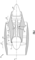
- FIG. 1 schematically illustrates a gas turbine engine 20.
- the example gas turbine engine 20 is a turbofan that generally incorporates a fan section 22, a compressor section 24, a combustor section 26 and a turbine section 28.
- the fan section 22 drives air along a bypass flow path B in a bypass duct defined within a nacelle 30.
- the turbine engine 20 intakes air along a core flow path C into the compressor section 24 for compression and communication into the combustor section 26.
- the compressed air is mixed with fuel from a fuel system 32 and ignited by igniter 34 to generate an exhaust gas flow that expands through the turbine section 28 and is exhausted through exhaust nozzle 36.
- turbofan turbine engine in the disclosed non-limiting embodiment, it should be understood that the concepts described herein are not limited to use with turbofans as the teachings may be applied to other types of turbine engines.
- the propulsor may be an enclosed fan. This may be applicable to an industrial gas turbine engine as well.
- a gas turbine engine as disclosed in this application will utilize gaseous fuel such as hydrogen (H 2 ).
- gaseous fuel such as hydrogen (H 2 ).
- H 2 gaseous fuel
- Challenges are faced by the use of hydrogen, and in particular combustor structure which might be appropriate for liquid aviation fuel may not be as applicable for hydrogen as a fuel.
- FIG 2A shows a combustor section 100 which is designed to delay ignition downstream of a hydrogen feed.
- the combustor 100 has a liner 102 (shown partially) extending around an axis of rotation of the engine such as the engine shown in Figure 1 .
- Ignition structure 34 is shown schematically.
- a mixing body 104 receives air through a plurality of air openings 106 in an end wall 199 of the body 104. That air passes into mixing passages 107, and extends forwardly towards a combustion chamber 105.
- Fuel is injected from a hydrogen feed 116 into a central inlet 118, and then into an open fuel plenum 120. Hydrogen fuel in the plenum 120 may then move into the mixing passages 107.
- small openings 122 communicate fuel from the plenum 120 into the mixing passages 107.
- Passage sections 108 extend downstream of the plenum 120, and may include structure to delay ignition.
- the structure may be a porous metal foam or cellular metallic materials (CMM).
- CCM cellular metallic materials
- Appropriate metals for use in combustion application are known.
- One potentially valuable metal foam would be formed of steel, such as Inconel ® .
- the fuel and air mix in the mixing passages 107 passes into passage sections 108 and into the combustion chamber 105 through an end face 110. Openings 112 are formed to allow the mixed fuel and air to move into the combustion chamber 105 from the passage sections 108.
- the ignition will occur downstream of the openings 112, and the passage sections 108.
- the included metal foam or cellular metallic materials (CMM) 114 will also resist flashback into the passage sections 108 and toward the plenum 120.
- the metal foam or CMM acts as a flame arrestor.
- the passage openings 112 can be sized to control the fuel-air mixture exit velocity higher than the local flame speed as another flashback avoidance control parameter as well.
- Figure 2B shows an outer periphery 124 of the combustor section 100. As can be seen the outer periphery is polygonal. One can see the passage sections 108 and the openings 122 communicating the plenum 122 and mixing passages 107. Moreover, metal foam 114 is also shown. While metal foam is specifically disclosed, any appropriate material having an open cell structure or as a cellular metallic material (CMM) may be utilized with this disclosure.
- CCM cellular metallic material
- the cellular material 114 is not just downstream of the location of openings 122, but also disposed at the location.
- FIG. 2C there are a plurality of combustor sections 100 having feed structure in discrete panels, such as shown in Figures 2A and 2B .
- Figure 3A shows a combustor section 200 in a distinct embodiment. Reference numerals that are similar to those disclosed with regard to Figure 2A have been changed to include the initial number 200. Again, ignition structure 234 is shown to delay combustion until the combustor chamber 205.
- the liner 202 surrounds a mixing body 204. Air openings 206 in end wall lead to passage sections 207. A gaseous hydrogen fuel supply 216 leads to a central passage 218, and then into an open plenum 220.
- Downstream passage sections 208 extends downstream beyond the plenum 220 and have openings 212 which communicates mixed fuel and air into the combustion chamber 205. Openings 222 allow fuel to flow from the plenum 220 into sections 208.
- the sections 208 are provided with an open cell structure 214 such as a metal foam or cellular metallic materials (CMM).
- a forward face 110 of the Figure 2A embodiment is generally perpendicular to a central axis of the engine.
- a forward face 210 of the Figure 3A embodiment has a shape which ends axially closer to the plenum 220 at more central locations as shown at opening 212B. More outward openings 212A extend further downstream.
- the concave shape of the inner face allows protrusion of the individual passages into the combustor to be of distinct lengths to optimize flame stability.
- Figure 3B shows the outer periphery 224 of the section 200 is generally cylindrical. Again, passage sections 208 receive open cell material 214. Openings 222 communicate fuel from the plenum 220 into the passage section 208.
- the central feed 218 can be used as a reference to understand that the passage sections 208 are positioned circumferentially and radially on each side of an axis of the central supply passage 218. Moreover, with regard to Figure 3A , passage sections 208 and opening 212B which are closer to the central feed 218 extend for the shorter axial length than do sections such as sections 208 and opening 212A spaced further from the central passage 218.
- a combustor 100/200 for a gas turbine engine under this disclosure could be said to include a liner 102/202 surrounding a fuel and air mixing body 104/204 and a fuel supply passage 118/218.
- the fuel supply passage communicates into an open fuel plenum 120/220 downstream of the fuel supply passage.
- a wall 199/299 of the mixing body has air openings 106/206 to receive air flow, and communicates air into mixing passages 107/207.
- the mixing passages pass through the fuel plenum. Fuel openings 122/222 in the mixing passages allow fuel to flow from the fuel plenum into the mixing passages and mix with the air. Passage sections 108/208 extend downstream of the fuel plenum, such that the mixed air and fuel travel downstream of the fuel plenum and into a combustion chamber 105/205.
- a combustor 100/200 for a gas turbine engine includes a liner 102/202 surrounding a gaseous fuel and air mixing body 104/204.
- a gaseous fuel supply passage 118/218 communicates into an open fuel plenum 120/220 downstream of the fuel supply passage.
- a wall of the mixing body has air openings 106/206 to receive air flow and communicate air into mixing passages 107/207.
- the mixing passages pass through the fuel plenum.
- Fuel openings 122/222 in the mixing passages allow fuel to flow from the fuel plenum into the mixing passages and mix with the air.
- Passage sections 108/208 extend downstream of the fuel plenum, such that the mixed air and fuel travels downstream of the fuel plenum and into a combustion chamber.
- a source of gaseous fuel is connected to the gaseous fuel supply passage, and the source of gaseous fuel is hydrogen.
- the mixing passages have at least two fuel openings 122 to communicate fuel from the fuel plenum into the mixing passages.
- an open cell material or cellular metallic material 114/214 (CMM) at least within the passage sections downstream of the fuel plenum.
- the at least one of the open cell material or cellular metallic material is also at a location of the fuel openings.
- the open cell material is used and is a metal foam.
- the fuel supply includes a central fuel passage at a generally central location in the mixing body, with the fuel plenum extending both circumferentially and radially on both sides of the central fuel passage.
- an inner face 210 of the mixing body 204 at the combustor is generally non-planar to an axis of the central fuel passage.
- At least some of said passage sections which are radially closer to the central fuel passage extend for a shorter axial length 212B than do other of said passage sections 212A spaced further from said central fuel passage.
Landscapes
- Engineering & Computer Science (AREA)
- Chemical & Material Sciences (AREA)
- Combustion & Propulsion (AREA)
- Mechanical Engineering (AREA)
- General Engineering & Computer Science (AREA)
- Pre-Mixing And Non-Premixing Gas Burner (AREA)
- Spray-Type Burners (AREA)
Abstract
Description
- This application relates to a combustor for a gas turbine engine wherein a fuel plenum receives a source of gaseous fuel, such as hydrogen, and has passages to mix the fuel with air.
- Gas turbine engines are known, and typically include a compressor delivering compressed air into a combustor. Compressed air is mixed with fuel and ignited. Products of the combustion pass downstream over turbine rotors, driving them to rotate. The turbine rotors in turn rotate the compressor rotors and propulsor rotors such as a fan or propeller.
- Historically, aviation fuel has been utilized with gas turbine engines, especially for aircraft applications. More recently it has been proposed to utilize hydrogen (H2) as a fuel.
- A combustor for a gas turbine engine according to an aspect of the present invention includes a liner surrounding a fuel and air mixing body. A fuel supply passage communicates into an open fuel plenum downstream of the fuel supply passage. A wall of the mixing body has air openings to receive air flow, and communicate air into mixing passages. The mixing passages pass through the fuel plenum. Fuel openings in the mixing passages allow fuel to flow from the mixing passage and mix with the air. There are passage sections extending downstream of the fuel plenum, such that the mixed air and fuel travels downstream of the fuel plenum and into a combustion chamber.
- In an embodiment, a source of gaseous fuel is connected to the gaseous fuel supply passage, and the source of gaseous fuel is hydrogen.
- In a further embodiment according to any of the previous embodiments, the mixing passages have at least two fuel openings to communicate fuel from the fuel plenum into the mixing passages.
- In a further embodiment according to any of the previous embodiments, there is at least one of an open cell material or cellular metallic material (CMM), at least within the passage sections downstream of the fuel plenum.
- In a further embodiment according to any of the previous embodiments, the at least one of the open cell material or cellular metallic material is also at a location of the fuel openings.
- In a further embodiment according to any of the previous embodiments, the open cell material is used and is a metal foam.
- In a further embodiment according to any of the previous embodiments, said fuel supply includes a central fuel passage at a generally central location in the mixing body, with the fuel plenum extending both circumferentially and radially on both sides of the central fuel passage.
- In a further embodiment according to any of the previous embodiments, an inner face of the mixing body at the combustor is generally non-planar to an axis of the central fuel passage.
- In a further embodiment according to any of the previous embodiments, at least some of said passage sections which are radially closer to the central fuel passage extend for a shorter axial length than do other of said passage sections spaced further from said central fuel passage.
- In a further embodiment according to any of the previous embodiments, there are a plurality of mixing bodies attached to the liner.
- A gas turbine engine according to another aspect of the present invention includes a compressor section, a turbine section and a combustor intermediate said compressor and said turbine. A gaseous fuel supply delivers fuel into a mixing body in the combustor, a liner surrounding the mixing body. The fuel supply communicates with a fuel supply passage, said fuel supply passage communicating into an open fuel plenum downstream of said fuel supply passage. A wall of the mixing body has air openings to receive air flow, and communicate air into mixing passages. The mixing passages pass through said fuel plenum. Fuel openings in the mixing passages allow fuel to flow from the fuel plenum into the mixing passages and mix with the air. There are passage sections extending downstream of the fuel plenum, such that said mixed air and fuel travels downstream of the fuel plenum and into a combustion chamber.
- In an embodiment, a source of gaseous fuel is connected to the fuel supply and the source of gaseous fuel is hydrogen.
- In a further embodiment according to any of the previous embodiments, the mixing passages have at least two fuel openings to communicate fuel from the fuel plenum into the passages.
- In a further embodiment according to any of the previous embodiments, there is at least one of an open cell material or cellular metallic materials (CMM), at least within the passage sections downstream of the fuel plenum.
- In a further embodiment according to any of the previous embodiments, the open cell material or cellular metallic material is also at a location of the fuel openings.
- In a further embodiment according to any of the previous embodiments, the open cell material is used and is a metal foam.
- In a further embodiment according to any of the previous embodiments, said fuel supply passage includes a central fuel passage at a generally central location in the mixing body, with the fuel plenum extending both circumferentially and radially on both sides of the central fuel passage.
- In a further embodiment according to any of the previous embodiments, an inner face of the mixing body at the combustor is generally non-planar to an axis of the central fuel passage.
- In a further embodiment according to any of the previous embodiments, at least some of the passage sections which are radially closer to the central fuel passage extend for a shorter axial length than do other of said passage sections spaced further from said central fuel passage.
- In a further embodiment according to any of the previous embodiments, there are a plurality of mixing bodies attached to the liner.
- These and other features will be best understood from the following drawings and specification, the following is a brief description.
-
-
Figure 1 schematically shows a gas turbine engine. -
Figure 2A shows a first embodiment combustor. -
Figure 2B is a view along line B-B ofFigure 2A . -
Figure 2C is an end view of a combustor according to this disclosure. -
Figure 3A shows a distinct embodiment combustor. -
Figure 3B is a view along line B-B ofFigure 3A . -
Figure 4 schematically shows an optional feature. -
Figure 1 schematically illustrates agas turbine engine 20. The examplegas turbine engine 20 is a turbofan that generally incorporates afan section 22, acompressor section 24, acombustor section 26 and aturbine section 28. Thefan section 22 drives air along a bypass flow path B in a bypass duct defined within anacelle 30. Theturbine engine 20 intakes air along a core flow path C into thecompressor section 24 for compression and communication into thecombustor section 26. In thecombustor section 26, the compressed air is mixed with fuel from afuel system 32 and ignited byigniter 34 to generate an exhaust gas flow that expands through theturbine section 28 and is exhausted throughexhaust nozzle 36. Although depicted as a turbofan turbine engine in the disclosed non-limiting embodiment, it should be understood that the concepts described herein are not limited to use with turbofans as the teachings may be applied to other types of turbine engines. As one example, rather than having the propulsor be an enclosed fan, the propulsor may be an open propeller. This may be applicable to an industrial gas turbine engine as well. - A gas turbine engine as disclosed in this application will utilize gaseous fuel such as hydrogen (H2). Challenges are faced by the use of hydrogen, and in particular combustor structure which might be appropriate for liquid aviation fuel may not be as applicable for hydrogen as a fuel.
- One challenge when utilizing hydrogen as a fuel is that it is in a gaseous state inside the combustor and more readily flammable than the liquid aviation fuel. This could raise challenges with flashback if the local flame speed is higher than the fuel-air mixture inlet speed into the combustor.
-
Figure 2A shows acombustor section 100 which is designed to delay ignition downstream of a hydrogen feed. Thecombustor 100 has a liner 102 (shown partially) extending around an axis of rotation of the engine such as the engine shown inFigure 1 .Ignition structure 34 is shown schematically. - A mixing
body 104 receives air through a plurality ofair openings 106 in anend wall 199 of thebody 104. That air passes into mixingpassages 107, and extends forwardly towards acombustion chamber 105. - Fuel is injected from a
hydrogen feed 116 into acentral inlet 118, and then into anopen fuel plenum 120. Hydrogen fuel in theplenum 120 may then move into the mixingpassages 107. - As shown, small openings 122 (See
Figure 2B ) communicate fuel from theplenum 120 into the mixingpassages 107.Passage sections 108 extend downstream of theplenum 120, and may include structure to delay ignition. - In one embodiment, the structure may be a porous metal foam or cellular metallic materials (CMM). Appropriate metals for use in combustion application are known. One potentially valuable metal foam would be formed of steel, such as Inconel®.
- The fuel and air mix in the mixing
passages 107 passes intopassage sections 108 and into thecombustion chamber 105 through anend face 110.Openings 112 are formed to allow the mixed fuel and air to move into thecombustion chamber 105 from thepassage sections 108. - By having the
passage sections 108 downstream of theplenum 120, the ignition will occur downstream of theopenings 112, and thepassage sections 108. The included metal foam or cellular metallic materials (CMM) 114 will also resist flashback into thepassage sections 108 and toward theplenum 120. Hence, the metal foam or CMM acts as a flame arrestor. Thepassage openings 112 can be sized to control the fuel-air mixture exit velocity higher than the local flame speed as another flashback avoidance control parameter as well. -
Figure 2B shows anouter periphery 124 of thecombustor section 100. As can be seen the outer periphery is polygonal. One can see thepassage sections 108 and theopenings 122 communicating theplenum 122 and mixingpassages 107. Moreover,metal foam 114 is also shown. While metal foam is specifically disclosed, any appropriate material having an open cell structure or as a cellular metallic material (CMM) may be utilized with this disclosure. - As is clear from
Figures 2A and 2B thecellular material 114 is not just downstream of the location ofopenings 122, but also disposed at the location. - As schematically shown in
Figure 2C , there are a plurality ofcombustor sections 100 having feed structure in discrete panels, such as shown inFigures 2A and 2B . -
Figure 3A shows acombustor section 200 in a distinct embodiment. Reference numerals that are similar to those disclosed with regard toFigure 2A have been changed to include theinitial number 200. Again,ignition structure 234 is shown to delay combustion until thecombustor chamber 205. Theliner 202 surrounds a mixingbody 204.Air openings 206 in end wall lead topassage sections 207. A gaseoushydrogen fuel supply 216 leads to acentral passage 218, and then into anopen plenum 220. -
Downstream passage sections 208 extends downstream beyond theplenum 220 and have openings 212 which communicates mixed fuel and air into thecombustion chamber 205.Openings 222 allow fuel to flow from theplenum 220 intosections 208. Thesections 208 are provided with anopen cell structure 214 such as a metal foam or cellular metallic materials (CMM). - As can be appreciated with a comparison of
Figures 2A and3A , aforward face 110 of theFigure 2A embodiment is generally perpendicular to a central axis of the engine. In contrast aforward face 210 of theFigure 3A embodiment has a shape which ends axially closer to theplenum 220 at more central locations as shown atopening 212B. Moreoutward openings 212A extend further downstream. The concave shape of the inner face allows protrusion of the individual passages into the combustor to be of distinct lengths to optimize flame stability. -
Figure 3B shows theouter periphery 224 of thesection 200 is generally cylindrical. Again,passage sections 208 receiveopen cell material 214.Openings 222 communicate fuel from theplenum 220 into thepassage section 208. - The
central feed 218 can be used as a reference to understand that thepassage sections 208 are positioned circumferentially and radially on each side of an axis of thecentral supply passage 218. Moreover, with regard toFigure 3A ,passage sections 208 andopening 212B which are closer to thecentral feed 218 extend for the shorter axial length than do sections such assections 208 andopening 212A spaced further from thecentral passage 218. - A
combustor 100/200 for a gas turbine engine under this disclosure could be said to include aliner 102/202 surrounding a fuel andair mixing body 104/204 and afuel supply passage 118/218. The fuel supply passage communicates into anopen fuel plenum 120/220 downstream of the fuel supply passage. Awall 199/299 of the mixing body hasair openings 106/206 to receive air flow, and communicates air into mixingpassages 107/207. - The mixing passages pass through the fuel plenum.
Fuel openings 122/222 in the mixing passages allow fuel to flow from the fuel plenum into the mixing passages and mix with the air.Passage sections 108/208 extend downstream of the fuel plenum, such that the mixed air and fuel travel downstream of the fuel plenum and into acombustion chamber 105/205. - While a single mixing device may be sufficient for a small combustor as shown in
Figures 2A-C ,3A and 3B , plural mixing bodies can be used on the dome of larger combustors spaced both circumferentially or radially. This is shown schematically as plural mixingbodies 204 inFigure 4 on aschematic combustor 300. - In a featured embodiment, a
combustor 100/200 for a gas turbine engine includes aliner 102/202 surrounding a gaseous fuel andair mixing body 104/204. A gaseousfuel supply passage 118/218 communicates into anopen fuel plenum 120/220 downstream of the fuel supply passage. A wall of the mixing body hasair openings 106/206 to receive air flow and communicate air into mixingpassages 107/207. The mixing passages pass through the fuel plenum.Fuel openings 122/222 in the mixing passages allow fuel to flow from the fuel plenum into the mixing passages and mix with the air.Passage sections 108/208 extend downstream of the fuel plenum, such that the mixed air and fuel travels downstream of the fuel plenum and into a combustion chamber. - In another embodiment according to the previous embodiment, a source of gaseous fuel is connected to the gaseous fuel supply passage, and the source of gaseous fuel is hydrogen.
- In another embodiment according to any of the previous embodiments, the mixing passages have at least two
fuel openings 122 to communicate fuel from the fuel plenum into the mixing passages. - In another embodiment according to any of the previous embodiments, there is at least one of an open cell material or cellular
metallic material 114/214 (CMM), at least within the passage sections downstream of the fuel plenum. - In another embodiment according to any of the previous embodiments, the at least one of the open cell material or cellular metallic material is also at a location of the fuel openings.
- In another embodiment according to any of the previous embodiments, the open cell material is used and is a metal foam.
- In another embodiment according to any of the previous embodiments, the fuel supply includes a central fuel passage at a generally central location in the mixing body, with the fuel plenum extending both circumferentially and radially on both sides of the central fuel passage.
- In another embodiment according to any of the previous embodiments, an
inner face 210 of the mixingbody 204 at the combustor is generally non-planar to an axis of the central fuel passage. - In another embodiment according to any of the previous embodiments, at least some of said passage sections which are radially closer to the central fuel passage extend for a shorter
axial length 212B than do other of saidpassage sections 212A spaced further from said central fuel passage. - In another embodiment according to any of the previous embodiments, there are a plurality of mixing
bodies 204 attached to the liner. - A gas turbine engine incorporating any of the above features is also disclosed and claimed.
- Although embodiments have been disclosed, a worker of skill in this art would recognize that modifications would come within the scope of this disclosure. For that reason, the following claims should be studied to determine the true scope and content.
Claims (12)
- A combustor (100; 200) for a gas turbine engine (20) comprising:a liner (102; 202) surrounding a gaseous fuel and air mixing body (104; 204);a gaseous fuel supply passage (118; 218), said fuel supply passage (118; 218) communicating into an open fuel plenum (120; 220) downstream of said fuel supply passage (118; 218);a wall (199; 299) of the mixing body (104; 204) having air openings (106; 206) to receive air flow, and communicate air into mixing passages (107; 207), said mixing passages (107; 207) passing through said fuel plenum (120; 220), fuel openings (122; 222) in the mixing passages (107; 207) allow fuel to flow from the fuel plenum (120; 220) into the mixing passages (107; 207) and mix with the air; andpassage sections (108; 208) extending downstream of the fuel plenum (120; 220), such that said mixed air and fuel travels downstream of the fuel plenum (120; 220) and into a combustion chamber (105; 205).
- The combustor (100; 200) as set forth in claim 1, wherein the mixing passages (107; 207) have at least two fuel openings (122; 222) to communicate fuel from the fuel plenum (120; 220) into the mixing passages (107; 207).
- The combustor (100; 200) as set forth in claim 1 or 2, wherein there is at least one of an open cell material or cellular metallic material (CMM) (114; 214), at least within the passage sections (108; 208) downstream of the fuel plenum (120; 220).
- The combustor (100; 200) as set forth in claim 3, wherein the at least one of the open cell material or cellular metallic material (114; 214) is also at a location of the fuel openings (122; 222).
- The combustor (100; 200) as set forth in claim 3 or 4, wherein the open cell material is used and is a metal foam (114; 214).
- The combustor (100; 200) as set forth in any preceding claim, wherein said fuel supply passage includes a central fuel passage (118; 218) at a generally central location in the mixing body (104; 204), with the fuel plenum (120; 220) extending both circumferentially and radially on both sides of the central fuel passage (118; 218).
- The combustor (200) as set forth in claim 6, wherein an inner face (210) of the mixing body (204) at the combustor (200) is generally non-planar to an axis of the central fuel passage (218).
- The combustor (200) as set forth in claim 6 or 7, wherein at least some of said passage sections (208) which are radially closer to the central fuel passage (218) extend for a shorter axial length than do other of said passage sections (208) spaced further from said central fuel passage (218).
- The combustor (100; 200) as set forth in any preceding claim, wherein there are a plurality of mixing bodies (104; 204) attached to the liner (102; 202).
- The combustor (100; 200) as set forth in any preceding claim, wherein a source of gaseous fuel is connected to the gaseous fuel supply passage (118; 218), and the source of gaseous fuel is hydrogen.
- A gas turbine engine (20) comprising:a compressor section (24) and a turbine section (28);a combustor (100; 200) as set forth in any of claims 1 to 9 intermediate said compressor (24) and said turbine (28); anda gaseous fuel supply (116; 216) delivering fuel into the mixing body (104; 204) in the combustor (100; 200), the fuel supply (116; 216) communicating with the fuel supply passage (118; 218).
- The gas turbine engine (20) as set forth in claim 11, wherein a source of gaseous fuel is connected to the fuel supply (116; 216) and the source of gaseous fuel is hydrogen.
Applications Claiming Priority (1)
| Application Number | Priority Date | Filing Date | Title |
|---|---|---|---|
| US18/105,012 US12607357B2 (en) | 2023-02-02 | 2023-02-02 | Combustor with fuel plenum and extending mixing passages |
Publications (2)
| Publication Number | Publication Date |
|---|---|
| EP4411246A1 true EP4411246A1 (en) | 2024-08-07 |
| EP4411246B1 EP4411246B1 (en) | 2026-04-01 |
Family
ID=89843560
Family Applications (1)
| Application Number | Title | Priority Date | Filing Date |
|---|---|---|---|
| EP24155634.9A Active EP4411246B1 (en) | 2023-02-02 | 2024-02-02 | Combustor with fuel plenum and extending mixing passages |
Country Status (3)
| Country | Link |
|---|---|
| US (1) | US12607357B2 (en) |
| EP (1) | EP4411246B1 (en) |
| CA (1) | CA3223827A1 (en) |
Citations (6)
| Publication number | Priority date | Publication date | Assignee | Title |
|---|---|---|---|---|
| US20080276618A1 (en) * | 2007-05-11 | 2008-11-13 | General Electric Company | Method and system for porous flame holder for hydrogen and syngas combustion |
| US20100192581A1 (en) * | 2009-02-04 | 2010-08-05 | General Electricity Company | Premixed direct injection nozzle |
| US20110083439A1 (en) * | 2009-10-08 | 2011-04-14 | General Electric Corporation | Staged Multi-Tube Premixing Injector |
| US20130104556A1 (en) * | 2011-10-26 | 2013-05-02 | General Electric Company | System and method for reducing combustion dynamics and nox in a combustor |
| US20140157779A1 (en) * | 2012-12-10 | 2014-06-12 | General Electric Company | SYSTEM FOR REDUCING COMBUSTION DYNAMICS AND NOx IN A COMBUSTOR |
| US20170211807A1 (en) * | 2014-04-07 | 2017-07-27 | Siemens Aktiengesellschaft | A burner tip and a burner for a gas turbine |
Family Cites Families (38)
| Publication number | Priority date | Publication date | Assignee | Title |
|---|---|---|---|---|
| US4100733A (en) | 1976-10-04 | 1978-07-18 | United Technologies Corporation | Premix combustor |
| US4578946A (en) | 1984-09-17 | 1986-04-01 | Sundstrand Corporation | Hydrazine fuel catalytic gas generator and injector therefor |
| US6267585B1 (en) | 1995-12-19 | 2001-07-31 | Daimlerchrysler Aerospace Airbus Gmbh | Method and combustor for combusting hydrogen |
| US5836289A (en) | 1997-06-10 | 1998-11-17 | Southwest Research Institute | Porous element fuel vaporizer |
| US6145496A (en) | 1998-04-07 | 2000-11-14 | Siemens Automotive Corporation | Fuel injector with porous element for atomizing fuel under air pressure |
| US7017329B2 (en) | 2003-10-10 | 2006-03-28 | United Technologies Corporation | Method and apparatus for mixing substances |
| US8266911B2 (en) | 2005-11-14 | 2012-09-18 | General Electric Company | Premixing device for low emission combustion process |
| WO2008097320A2 (en) | 2006-06-01 | 2008-08-14 | Virginia Tech Intellectual Properties, Inc. | Premixing injector for gas turbine engines |
| US20080104961A1 (en) | 2006-11-08 | 2008-05-08 | Ronald Scott Bunker | Method and apparatus for enhanced mixing in premixing devices |
| US7832212B2 (en) | 2006-11-10 | 2010-11-16 | General Electric Company | High expansion fuel injection slot jet and method for enhancing mixing in premixing devices |
| US8099960B2 (en) | 2006-11-17 | 2012-01-24 | General Electric Company | Triple counter rotating swirler and method of use |
| US8661779B2 (en) | 2008-09-26 | 2014-03-04 | Siemens Energy, Inc. | Flex-fuel injector for gas turbines |
| EP2299178B1 (en) | 2009-09-17 | 2015-11-04 | Alstom Technology Ltd | A method and gas turbine combustion system for safely mixing H2-rich fuels with air |
| US8794545B2 (en) | 2009-09-25 | 2014-08-05 | General Electric Company | Internal baffling for fuel injector |
| JP5084847B2 (en) | 2010-01-13 | 2012-11-28 | 株式会社日立製作所 | Gas turbine combustor |
| US20120058437A1 (en) * | 2010-09-08 | 2012-03-08 | General Electric Company | Apparatus and method for mixing fuel in a gas turbine nozzle |
| US8893500B2 (en) | 2011-05-18 | 2014-11-25 | Solar Turbines Inc. | Lean direct fuel injector |
| JP5630424B2 (en) | 2011-11-21 | 2014-11-26 | 三菱日立パワーシステムズ株式会社 | Gas turbine combustor |
| JP5926635B2 (en) | 2012-07-04 | 2016-05-25 | 三菱日立パワーシステムズ株式会社 | Gas turbine combustor |
| US8904798B2 (en) * | 2012-07-31 | 2014-12-09 | General Electric Company | Combustor |
| CA2830031C (en) | 2012-10-23 | 2016-03-15 | Alstom Technology Ltd. | Burner for a can combustor |
| US9360220B2 (en) | 2012-11-06 | 2016-06-07 | General Electric Company | Micro-mixer nozzle |
| CN104075344B (en) | 2013-03-25 | 2016-07-06 | 通用电气公司 | Start and operate fuel nozzle system and the method for gas turbine with low calorie fuels |
| JP6602004B2 (en) | 2014-09-29 | 2019-11-06 | 川崎重工業株式会社 | Fuel injector and gas turbine |
| JP6460716B2 (en) | 2014-10-14 | 2019-01-30 | 三菱重工業株式会社 | Fuel injector |
| JP2016109309A (en) | 2014-12-02 | 2016-06-20 | 川崎重工業株式会社 | Combustor for gas turbine, and gas turbine |
| JP2016148507A (en) | 2014-12-30 | 2016-08-18 | ゼネラル・エレクトリック・カンパニイ | Pilot nozzle in gas turbine combustor |
| WO2016122521A1 (en) | 2015-01-29 | 2016-08-04 | Siemens Energy, Inc. | Fuel injector including a lobed mixer and vanes for injecting alternate fuels in a gas turbine |
| WO2016122529A1 (en) | 2015-01-29 | 2016-08-04 | Siemens Energy, Inc. | Fuel injector including tandem vanes for injecting alternate fuels in a gas turbine |
| EP3098514A1 (en) | 2015-05-29 | 2016-11-30 | Siemens Aktiengesellschaft | Combustor arrangement |
| CN107735618B (en) | 2015-07-06 | 2020-06-26 | 西门子股份公司 | Combustor for a gas turbine and method of operating a combustor |
| US10024539B2 (en) | 2015-09-24 | 2018-07-17 | General Electric Company | Axially staged micromixer cap |
| US20170227224A1 (en) | 2016-02-09 | 2017-08-10 | Solar Turbines Incorporated | Fuel injector for combustion engine system, and engine operating method |
| US9976522B2 (en) | 2016-04-15 | 2018-05-22 | Solar Turbines Incorporated | Fuel injector for combustion engine and staged fuel delivery method |
| US10502425B2 (en) | 2016-06-03 | 2019-12-10 | General Electric Company | Contoured shroud swirling pre-mix fuel injector assembly |
| US10295190B2 (en) | 2016-11-04 | 2019-05-21 | General Electric Company | Centerbody injector mini mixer fuel nozzle assembly |
| GB2593123A (en) | 2019-06-25 | 2021-09-22 | Siemens Ag | Combustor for a gas turbine |
| US11506390B2 (en) | 2019-12-06 | 2022-11-22 | Raytheon Technologies Corporation | Multi-fuel bluff-body piloted high-shear injector and method of using same |
-
2023
- 2023-02-02 US US18/105,012 patent/US12607357B2/en active Active
- 2023-12-19 CA CA3223827A patent/CA3223827A1/en active Pending
-
2024
- 2024-02-02 EP EP24155634.9A patent/EP4411246B1/en active Active
Patent Citations (6)
| Publication number | Priority date | Publication date | Assignee | Title |
|---|---|---|---|---|
| US20080276618A1 (en) * | 2007-05-11 | 2008-11-13 | General Electric Company | Method and system for porous flame holder for hydrogen and syngas combustion |
| US20100192581A1 (en) * | 2009-02-04 | 2010-08-05 | General Electricity Company | Premixed direct injection nozzle |
| US20110083439A1 (en) * | 2009-10-08 | 2011-04-14 | General Electric Corporation | Staged Multi-Tube Premixing Injector |
| US20130104556A1 (en) * | 2011-10-26 | 2013-05-02 | General Electric Company | System and method for reducing combustion dynamics and nox in a combustor |
| US20140157779A1 (en) * | 2012-12-10 | 2014-06-12 | General Electric Company | SYSTEM FOR REDUCING COMBUSTION DYNAMICS AND NOx IN A COMBUSTOR |
| US20170211807A1 (en) * | 2014-04-07 | 2017-07-27 | Siemens Aktiengesellschaft | A burner tip and a burner for a gas turbine |
Also Published As
| Publication number | Publication date |
|---|---|
| US12607357B2 (en) | 2026-04-21 |
| US20240263789A1 (en) | 2024-08-08 |
| CA3223827A1 (en) | 2025-04-14 |
| EP4411246B1 (en) | 2026-04-01 |
Similar Documents
| Publication | Publication Date | Title |
|---|---|---|
| US6931862B2 (en) | Combustor system for an expendable gas turbine engine | |
| EP2900977B1 (en) | Gas turbine engine combustor | |
| EP1939438A2 (en) | Duct burning mixed flow turbofan | |
| CN109028149A (en) | Variable geometry rotary detonation combustor and method of operation | |
| US20190017437A1 (en) | Continuous detonation gas turbine engine | |
| EP3434980B1 (en) | Reverse flow combustor | |
| EP4411244A1 (en) | Combustor with distributed air and fuel mixing | |
| EP4411246B1 (en) | Combustor with fuel plenum and extending mixing passages | |
| EP4411232A1 (en) | High shear fuel distributor | |
| EP4411241A1 (en) | Fuel system with pilot and main injectors for hydrogen-driven gas turbine engine | |
| EP4411226A1 (en) | Central air passage with radial fuel distributor | |
| EP4411233A1 (en) | Combustor with fuel plenum with mixing passages having baffles | |
| EP4411225B1 (en) | Combustor with air/fuel mixer creating mixed cloud | |
| EP4411242B1 (en) | Combustor with central fuel injection and downstream air mixing | |
| EP4411227B1 (en) | Combustor with tangential fuel and air flow | |
| EP4411238B1 (en) | Combustor with helix air and fuel mixing passage | |
| EP4411245B1 (en) | Combustor with fuel and air mixing plenum |
Legal Events
| Date | Code | Title | Description |
|---|---|---|---|
| PUAI | Public reference made under article 153(3) epc to a published international application that has entered the european phase |
Free format text: ORIGINAL CODE: 0009012 |
|
| STAA | Information on the status of an ep patent application or granted ep patent |
Free format text: STATUS: THE APPLICATION HAS BEEN PUBLISHED |
|
| AK | Designated contracting states |
Kind code of ref document: A1 Designated state(s): AL AT BE BG CH CY CZ DE DK EE ES FI FR GB GR HR HU IE IS IT LI LT LU LV MC ME MK MT NL NO PL PT RO RS SE SI SK SM TR |
|
| STAA | Information on the status of an ep patent application or granted ep patent |
Free format text: STATUS: REQUEST FOR EXAMINATION WAS MADE |
|
| 17P | Request for examination filed |
Effective date: 20250207 |
|
| GRAP | Despatch of communication of intention to grant a patent |
Free format text: ORIGINAL CODE: EPIDOSNIGR1 |
|
| STAA | Information on the status of an ep patent application or granted ep patent |
Free format text: STATUS: GRANT OF PATENT IS INTENDED |
|
| INTG | Intention to grant announced |
Effective date: 20251006 |
|
| GRAS | Grant fee paid |
Free format text: ORIGINAL CODE: EPIDOSNIGR3 |
|
| GRAA | (expected) grant |
Free format text: ORIGINAL CODE: 0009210 |
|
| STAA | Information on the status of an ep patent application or granted ep patent |
Free format text: STATUS: THE PATENT HAS BEEN GRANTED |
|
| AK | Designated contracting states |
Kind code of ref document: B1 Designated state(s): AL AT BE BG CH CY CZ DE DK EE ES FI FR GB GR HR HU IE IS IT LI LT LU LV MC ME MK MT NL NO PL PT RO RS SE SI SK SM TR |
|
| REG | Reference to a national code |
Ref country code: CH Ref legal event code: F10 Free format text: ST27 STATUS EVENT CODE: U-0-0-F10-F00 (AS PROVIDED BY THE NATIONAL OFFICE) Effective date: 20260401 Ref country code: GB Ref legal event code: FG4D |
|
| REG | Reference to a national code |
Ref country code: DE Ref legal event code: R096 Ref document number: 602024003501 Country of ref document: DE |
|
| REG | Reference to a national code |
Ref country code: IE Ref legal event code: FG4D |