EP2299178B1 - A method and gas turbine combustion system for safely mixing H2-rich fuels with air - Google Patents
A method and gas turbine combustion system for safely mixing H2-rich fuels with air Download PDFInfo
- Publication number
- EP2299178B1 EP2299178B1 EP09170508.7A EP09170508A EP2299178B1 EP 2299178 B1 EP2299178 B1 EP 2299178B1 EP 09170508 A EP09170508 A EP 09170508A EP 2299178 B1 EP2299178 B1 EP 2299178B1
- Authority
- EP
- European Patent Office
- Prior art keywords
- burner
- air
- premixer
- fuel
- gas turbine
- Prior art date
- Legal status (The legal status is an assumption and is not a legal conclusion. Google has not performed a legal analysis and makes no representation as to the accuracy of the status listed.)
- Not-in-force
Links
Images


Classifications
-
- F—MECHANICAL ENGINEERING; LIGHTING; HEATING; WEAPONS; BLASTING
- F23—COMBUSTION APPARATUS; COMBUSTION PROCESSES
- F23R—GENERATING COMBUSTION PRODUCTS OF HIGH PRESSURE OR HIGH VELOCITY, e.g. GAS-TURBINE COMBUSTION CHAMBERS
- F23R3/00—Continuous combustion chambers using liquid or gaseous fuel
- F23R3/28—Continuous combustion chambers using liquid or gaseous fuel characterised by the fuel supply
- F23R3/286—Continuous combustion chambers using liquid or gaseous fuel characterised by the fuel supply having fuel-air premixing devices
-
- F—MECHANICAL ENGINEERING; LIGHTING; HEATING; WEAPONS; BLASTING
- F02—COMBUSTION ENGINES; HOT-GAS OR COMBUSTION-PRODUCT ENGINE PLANTS
- F02C—GAS-TURBINE PLANTS; AIR INTAKES FOR JET-PROPULSION PLANTS; CONTROLLING FUEL SUPPLY IN AIR-BREATHING JET-PROPULSION PLANTS
- F02C3/00—Gas-turbine plants characterised by the use of combustion products as the working fluid
- F02C3/20—Gas-turbine plants characterised by the use of combustion products as the working fluid using a special fuel, oxidant, or dilution fluid to generate the combustion products
- F02C3/30—Adding water, steam or other fluids for influencing combustion, e.g. to obtain cleaner exhaust gases
-
- F—MECHANICAL ENGINEERING; LIGHTING; HEATING; WEAPONS; BLASTING
- F23—COMBUSTION APPARATUS; COMBUSTION PROCESSES
- F23L—SUPPLYING AIR OR NON-COMBUSTIBLE LIQUIDS OR GASES TO COMBUSTION APPARATUS IN GENERAL ; VALVES OR DAMPERS SPECIALLY ADAPTED FOR CONTROLLING AIR SUPPLY OR DRAUGHT IN COMBUSTION APPARATUS; INDUCING DRAUGHT IN COMBUSTION APPARATUS; TOPS FOR CHIMNEYS OR VENTILATING SHAFTS; TERMINALS FOR FLUES
- F23L7/00—Supplying non-combustible liquids or gases, other than air, to the fire, e.g. oxygen, steam
-
- F—MECHANICAL ENGINEERING; LIGHTING; HEATING; WEAPONS; BLASTING
- F23—COMBUSTION APPARATUS; COMBUSTION PROCESSES
- F23C—METHODS OR APPARATUS FOR COMBUSTION USING FLUID FUEL OR SOLID FUEL SUSPENDED IN A CARRIER GAS OR AIR
- F23C2900/00—Special features of, or arrangements for combustion apparatus using fluid fuels or solid fuels suspended in air; Combustion processes therefor
- F23C2900/9901—Combustion process using hydrogen, hydrogen peroxide water or brown gas as fuel
-
- F—MECHANICAL ENGINEERING; LIGHTING; HEATING; WEAPONS; BLASTING
- F23—COMBUSTION APPARATUS; COMBUSTION PROCESSES
- F23L—SUPPLYING AIR OR NON-COMBUSTIBLE LIQUIDS OR GASES TO COMBUSTION APPARATUS IN GENERAL ; VALVES OR DAMPERS SPECIALLY ADAPTED FOR CONTROLLING AIR SUPPLY OR DRAUGHT IN COMBUSTION APPARATUS; INDUCING DRAUGHT IN COMBUSTION APPARATUS; TOPS FOR CHIMNEYS OR VENTILATING SHAFTS; TERMINALS FOR FLUES
- F23L2900/00—Special arrangements for supplying or treating air or oxidant for combustion; Injecting inert gas, water or steam into the combustion chamber
- F23L2900/07002—Injecting inert gas, other than steam or evaporated water, into the combustion chambers
-
- Y—GENERAL TAGGING OF NEW TECHNOLOGICAL DEVELOPMENTS; GENERAL TAGGING OF CROSS-SECTIONAL TECHNOLOGIES SPANNING OVER SEVERAL SECTIONS OF THE IPC; TECHNICAL SUBJECTS COVERED BY FORMER USPC CROSS-REFERENCE ART COLLECTIONS [XRACs] AND DIGESTS
- Y02—TECHNOLOGIES OR APPLICATIONS FOR MITIGATION OR ADAPTATION AGAINST CLIMATE CHANGE
- Y02E—REDUCTION OF GREENHOUSE GAS [GHG] EMISSIONS, RELATED TO ENERGY GENERATION, TRANSMISSION OR DISTRIBUTION
- Y02E20/00—Combustion technologies with mitigation potential
- Y02E20/34—Indirect CO2mitigation, i.e. by acting on non CO2directly related matters of the process, e.g. pre-heating or heat recovery
Definitions
- the present invention relates to gas turbines. It refers to a method for safely mixing H2-rich fuels with air in a gas turbine combustion system.
- FIG. 1 shows laminar flame speeds for CH4 (the standard gas turbine fuel) and for various H2/N2 mixtures.
- H2-rich laminar flame speeds differ from their CH4 counterparts in that:
- ⁇ can vary between 0 and infinity.
- the flammability limits are rather narrow. On the rich side, a flame cannot be sustained, even at relatively high ( ⁇ 0.7 in Figure 1 ). The burning velocity (and hence laminar flame speed) is generally low, particularly near the rich extinction limit. The risk of ignition in the injection area is low, and there is insufficient anchoring in the event of flashback (i.e. the flame is blown off).
- the flammability limits are very wide, with very rich mixtures ( ⁇ ⁇ 0.3) capable of sustaining a flame.
- the burning velocities (and hence laminar flame speeds) are high.
- US 20040226299 discloses a method for safely mixing H 2 -rich fuels with air in a gas turbine combustion system.
- It is an object of the present invention to provide a method for safely mixing H2-rich fuels with air in gas turbine combustion systems, which effectively permits the local fuel/air mixture to bypass the peak burning velocity (i.e. ⁇ 0.6) prior to injection into the main burner air stream (known as liner air), thereby avoiding the shortcomings of the state of the art.
- said premixing step is done in a manner which prevents flame anchoring near the injection location and in the burner.
- an air excess factor of ⁇ > 1, preferably of ⁇ > 1.3, is achieved in said premixing step.
- air is separated into 02 and N2 by means of an air separation unit (ASU), and a portion of the N2 from the air separation unit (ASU) is added to the main burner air and/or pre-premixed fuel/air mixture.
- ASU air separation unit
- a pre-premixer in the form of a simple, preferably round, channel with straight or slightly swirling air flow is used to avoid recirculation and/or stagnation regions.
- a pre-premixer consisting of narrow channels whose hydraulic diameter is less than the quenching distance, is used.
- the boundary layers of the air flow in said pre-premixer are energized, especially by using some film air, in order to increase velocities these regions.
- the air flow is additionally accelerated via the "jet-pump" effect of injecting large volumes of H2/N2 fuel.
- water mist is injected into the H2-rich fuel to enhance the safety of the method by means of the relative cooling due to the subsequent evaporation of said injected water.
- a main swirler in a swirl-stabilized burner is utilized to further increase the velocity in the pre-premixer by taking advantage of the fact that the local static pressure in the central region of the burner is lower than the nominal burner pressure.
- a gas turbine combustion system for applying the method according to the invention comprises:
- the at least one pre-premixer has the form of a simple, preferably round, channel with straight or slightly swirling air flow.
- the at least one pre-premixer consists of narrow channels whose hydraulic diameter is less than the quenching distance.
- said at least one burner is a swirl-stabilized burner.
- said at least one burner is a so-called EV burner (in place of many: EP 0 321 809 B1 ) or a so-called AEV burner (in place of many: EP 0 704 657 ).
- said at least one burner is a so-called SEV burner (in place of many: EP 0 620 362 B1 , pos. 5).
- the object of the present invention is achieved by premixing all of the fuel with a portion of burner air (denoted as "pre-premixing air”) in a manner which prevents flame anchoring, and then injecting this fuel/air mixture (characterized by ⁇ > 1, preferably ⁇ > 1.3) into the main burner air stream (i.e. the liner air); this can be done in one or more stages.
- Figure 2 illustrates the concept (which is called "pre-premixing").
- P_pk2 and T_pk2 are the pressure and temperature, respectively, at the compressor exit of the gas turbine.
- P_fuel and T_fuel are the pressure and temperature, respectively, of the fuel
- T_mix is the temperature of the pre-premixing mixture
- P_hood and T_hood are the pressure and temperature, respectively, of the hood air (which is the air that enters the burner).
- the pre-premixing method can involve elements of the traditional solutions for H2-rich fuels (e.g. high air velocities, high dilution levels), but the negative effects are rather limited since these methods only apply to a portion of the overall burner air (i.e. the pre-premixing air), rather than the entire burner air flow.
- the pre-premixing process is driven by a pressure loss ( ⁇ P) that is larger than that across the burner.
- ⁇ P pressure loss
- FIG. 3 is an example of a burner encompassing the new pre-premixing concept described above.
- a pre-premixed fuel/air mixture C is injected through pre-premixers 11 and 12 into a burner 17 which opens into a combustion chamber 13.
- Main air 22 is added through main burner air inlets 14 and 15 near the exit of the pre-premixers 11, 12.
- One or more pre-premixers may be provided per burner.
- the idea can be used for SEV (i.e. reheat) combustion as well.
- the pre-premixer temperature benefit would be even greater since the PK2 air used in the pre-premixer is much colder (typically 400 °C - 450 °C) than the 1000 °C of the main burner air.
- a similar benefit would be seen in the application to non-reheat lean-premix burners in recuperated combustion systems.
- the pre-premixing concept can be applied to diffusion burners too. Such a configuration would permit clean and safe operation without derating (diffusion burners often have to run on lower firing temperatures for NOx reasons) and without the need for excessive dilution.
- a combustion system 20 comprises a burner 17 with a pre-premixer 16.
- a pre-premixed fuel/air mixture 21 generated within the pre-premixer 16 enters the burner 17 in axial direction (axis 19).
- Main air 22 enters the burner 17 via a hood 18, thereby generating a swirl with a low static pressure region 24.
- the resulting fully premixed fuel/air mixture 23 exits the burner 17 to enter the subsequent combustion chamber.
- the main air flow i.e. "hood” or liner air
- the main air flow can enter the burner via axial, radial or "hybrid" swirlers.
Landscapes
- Engineering & Computer Science (AREA)
- Chemical & Material Sciences (AREA)
- Combustion & Propulsion (AREA)
- Mechanical Engineering (AREA)
- General Engineering & Computer Science (AREA)
Description
- The present invention relates to gas turbines. It refers to a method for safely mixing H2-rich fuels with air in a gas turbine combustion system.
- Current combustors for hydrogen-rich fuels rely upon very high levels of dilution (with inert species, e.g. N2 and/or steam) of diffusion flames (
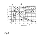
WO-A1-2008/135362 ;WO-A1-2008/155242 ). Derating (i.e. reducing flame temperatures) is also commonly resorted to (see for exampleEP-A1-0 731 255 orEP-A1-0 899 438 ). Efforts are being made to develop lean-premix combustion systems for hydrogen-rich fuels in order to further reduce emissions and to minimize costly diluents. Such systems require a high degree of premixing. Unfortunately, hydrogen-rich fuels are so reactive that significant modifications are necessary in order to safely and cleanly burn these fuels. The modifications (e.g. increasing burner velocity, using very high fuel jet velocities), however, are mostly incompatible with the requirements of modern gas turbine burners (low burner pressure loss, low fuel pressure loss). - The problem with introducing H2-rich fuels into air in order to attain a good air/fuel mixture prior to combustion is exemplified by
Figure 1 , which shows laminar flame speeds for CH4 (the standard gas turbine fuel) and for various H2/N2 mixtures. H2-rich laminar flame speeds differ from their CH4 counterparts in that: - The peak flame speed is at least 6 times higher.
- The flame speed in the entire range of usable fuel/air mixtures is higher than for CH4.
- The peak flame speed occurs at the much lower air excess factor (λ) of approx. 0.6, rather than approx. 1.0.
- In actual fact, it is the turbulent burning velocity that largely determines the flame location in a real burner. This parameter exacerbates the situation for H2-rich fuels, given that the turbulent burning velocity is a function of pressure for H2 but not so for CH4.
- When fuel is injected into hot air, the region near the injection point is characterized by very poor mixing. On a local scale, λ can vary between 0 and infinity.
- The flammability limits are rather narrow. On the rich side, a flame cannot be sustained, even at relatively high (≈ 0.7 in
Figure 1 ). The burning velocity (and hence laminar flame speed) is generally low, particularly near the rich extinction limit. The risk of ignition in the injection area is low, and there is insufficient anchoring in the event of flashback (i.e. the flame is blown off). - The flammability limits are very wide, with very rich mixtures (λ < 0.3) capable of sustaining a flame. The burning velocities (and hence laminar flame speeds) are high. Unfortunately, the peak reactivity of H2-rich fuels is also in the rich region (typically around lambda = 0.5), which means that the risk of ignition in the injection area is very high, and the flame anchoring (once flame jump occurs) is very strong. Flashback thus results in permanent flame anchoring, which leads to high emissions and possibly also to hardware destruction.
- Common methods of dealing with such high burning velocities, and the drawbacks thereof, are listed below. None of these traditional solutions, however, address the critical issue of high flammability of very rich fuel/air mixtures.
- Utilizing dilution. At any given mixing quality, this action reduces the burning velocity (see dotted double arrow A in
Figure 1 ), but not sufficiently. Furthermore, this action does not shift the equivalence ratio at which peak burning velocities occur. Excessive dilution results in high fuel pressure losses and additional costs (The diluent is not free. In the case of N2, its pressure must be increased from that of the air separation unit to that of the fuel. In the case of steam, there is a loss of efficiency associated with extracting steam from the steam cycle). - Significantly increasing the burner air velocity. In order to be effective, the burner velocity must be increased by a large amount, thereby resulting in larger pressure losses across the burner and hence reduction in gas turbine efficiency. Furthermore, such high burner velocities tend to be incompatible with the standard backup fuels (e.g. Natural Gas). It must be noted that there will always be regions of lower air velocity (e.g. boundary layers), which are often near those locations from which fuel is injected.
- Injecting fuel at higher velocities in order to avoid flame-holding. Excessive jet velocities cause high-pressure losses in the fuel system, resulting in higher costs. Approaching the sonic limit also poses stability problems.
-
US 20040226299 discloses a method for safely mixing H2-rich fuels with air in a gas turbine combustion system. - It is an object of the present invention to provide a method for safely mixing H2-rich fuels with air in gas turbine combustion systems, which effectively permits the local fuel/air mixture to bypass the peak burning velocity (i.e. λ = 0.6) prior to injection into the main burner air stream (known as liner air), thereby avoiding the shortcomings of the state of the art.
- This object is obtained by a method according to
claim 1. - According to one embodiment of the invention said premixing step is done in a manner which prevents flame anchoring near the injection location and in the burner.
- According to another embodiment of the invention an air excess factor of λ > 1, preferably of λ > 1.3, is achieved in said premixing step.
- According to another embodiment of the invention air is separated into 02 and N2 by means of an air separation unit (ASU), and a portion of the N2 from the air separation unit (ASU) is added to the main burner air and/or pre-premixed fuel/air mixture.
- According to a further embodiment of the invention a pre-premixer in the form of a simple, preferably round, channel with straight or slightly swirling air flow is used to avoid recirculation and/or stagnation regions.
- According to another embodiment of the invention a pre-premixer consisting of narrow channels whose hydraulic diameter is less than the quenching distance, is used.
- According to another embodiment of the invention the boundary layers of the air flow in said pre-premixer are energized, especially by using some film air, in order to increase velocities these regions.
- According to a further embodiment of the invention the air flow is additionally accelerated via the "jet-pump" effect of injecting large volumes of H2/N2 fuel.
- According to another embodiment of the invention water mist is injected into the H2-rich fuel to enhance the safety of the method by means of the relative cooling due to the subsequent evaporation of said injected water.
- According to a further embodiment of the invention a main swirler in a swirl-stabilized burner is utilized to further increase the velocity in the pre-premixer by taking advantage of the fact that the local static pressure in the central region of the burner is lower than the nominal burner pressure.
- A gas turbine combustion system for applying the method according to the invention comprises:
- a combustion chamber and at least one burner opening into said combustion chamber to inject a stream of burner air into said combustion chamber;
- at least one pre-premixer for providing a pre-premixed fuel/air mixture;
- According to an embodiment of the inventive gas turbine combustion system, the at least one pre-premixer has the form of a simple, preferably round, channel with straight or slightly swirling air flow.
- According to another embodiment of the inventive gas turbine combustion system, the at least one pre-premixer consists of narrow channels whose hydraulic diameter is less than the quenching distance.
- According to an embodiment of the inventive gas turbine combustion system, said at least one burner is a swirl-stabilized burner.
- According to an embodiment of the inventive gas turbine combustion system, said at least one burner is a so-called EV burner (in place of many:
EP 0 321 809 B1 ) or a so-called AEV burner (in place of many:EP 0 704 657 ). - According to an embodiment of the inventive gas turbine combustion system, said at least one burner is a so-called SEV burner (in place of many:
EP 0 620 362 B1 , pos. 5). - The present invention is now to be explained more closely by means of different embodiments and with reference to the attached drawings.
- Fig. 1
- shows laminar flame speeds for CH4 (the standard gas turbine fuel) and for various H2/N2 mixtures at 1 atm and 20 °C;
- Fig. 2
- illustrates the pre-premixing concept according to the invention;
- Fig. 3
- shows an exemplary embodiment of a burner encompassing the pre-premixing concept according to the invention; and
- Fig. 4
- demonstrates that the main swirler in a swirl-stabilized burner can be utilized to further increase the velocity in the pre-premixer, simply by taking advantage of the fact that the local static pressure in the central region of the burner is lower than the nominal burner pressure.
- The object of the present invention is achieved by premixing all of the fuel with a portion of burner air (denoted as "pre-premixing air") in a manner which prevents flame anchoring, and then injecting this fuel/air mixture (characterized by λ > 1, preferably λ > 1.3) into the main burner air stream (i.e. the liner air); this can be done in one or more stages.
Figure 2 illustrates the concept (which is called "pre-premixing"). P_pk2 and T_pk2 are the pressure and temperature, respectively, at the compressor exit of the gas turbine. P_fuel and T_fuel are the pressure and temperature, respectively, of the fuel, T_mix is the temperature of the pre-premixing mixture, while P_hood and T_hood are the pressure and temperature, respectively, of the hood air (which is the air that enters the burner). The pre-premixing method can involve elements of the traditional solutions for H2-rich fuels (e.g. high air velocities, high dilution levels), but the negative effects are rather limited since these methods only apply to a portion of the overall burner air (i.e. the pre-premixing air), rather than the entire burner air flow. - Mass and energy balances show that about 25% and 45% of the total burner air is needed such that the pre-premixed fuel/air has a λ of 0.6 and 1.0, respectively, for a 70/30 H2/N2 fuel (air temperature 420 °C, fuel temperature 150 °C, T_ad = 1750K).
- In the event that the resulting liner cooling is insufficient (because part of the compressor air was diverted to the pre-premixer), it would be possible to add the remaining N2 from the ASU (air separation unit) to the liner air, the mixture temperature of which would be significantly below the standard liner air temperature of 400 °C. This stream of N2 would only have to be compressed from the ASU pressure (approx. 5bar for a low-pressure device, or 15bar for a high-pressure ASU) to the P_pk2 pressure (i.e. at compressor exit).
- The pre-premixing process is driven by a pressure loss (ΔP) that is larger than that across the burner.
Figure 2 - based on a GT13E2 gas turbine of the applicant under full-load conditions for an AEV-125 burner (AEV= Advanced Environmental) - shows that, typically, this pressure loss is proportional to the sum of the liner and swirler pressure losses, ΔP_liner and ΔP_swirler, amounting to ΔP ≈ 2 to 3%. - Further safety benefits of the pre-premixing concept are noted:
- The relatively cold fuel is mixed with only a portion of the entire burner air, meaning that the pre-premixed mixture temperature T_mix is significantly lower (278 °C and 310 °C for λ = 0.6 and 1.0, respectively, compared to 350 °C when the fuel is mixed with all the burner air (based on 70/30 H2/N2 at 150 °C). This strongly reduces the reactivity of the air/fuel mixture, thereby greatly assisting the safe transition to λ ≥ 1).
- The pre-premixing air stream is cooler than the hood air (by around 20 °C), since it is not used for liner cooling. This further reduces reactivity in the pre-premixer.
- If N2 is used for a part of the pre-premixing air, then the risk of ignition is reduced due to
- o lower 02; and
- o lower temperature.
- The pre-premixed mixture can achieve much greater penetration depths in the burner (due to the higher fuel mass flow rates relative to the air mass flow), thereby permitting better mixing than when the non-pre-premixed fuel is injected into the burner.
- Several methods of achieving the desired pre-premixing are described below. There are undoubtedly other means of achieving the proposed idea.
- The pre-premixer (16 in
Figure 4 ) can consist of a simple channel (preferably round) with straight air flow. Aerodynamically simple geometries avoid recirculation and/or stagnation regions. The boundary layers can be energized (e.g. using some film air) in order to increase velocities these regions. Both jet in cross-flow and co-flowing jets can be used. The latter further reduce risk of flame anchoring.- ○ Lack of swirl in the pre-premixer means that the air velocity can be around 50% higher than that in the burner (approx 120m/s), using the given ΔP.
- ○ The air flow can additionally be accelerated via the "jet-pump" effect of injecting large volumes of H2/N2 fuel.
- The pre-premixer can consist of small channels whose hydraulic diameter is less than the quenching distance. Injection and pre-mixing of the fuel in these small channels prevents homogeneous ignition from occurring during the mixing process and prior to the attainment of higher λ. The air velocity can be small, since safety is now promoted by quenching rather than by convection. Small air velocities in narrow channels are compatible with the available ΔP.
- An injection of water into H2-rich fuel and relative cooling by subsequent evaporation would further enhance the safety of the present methodology.
-
Figure 3 is an example of a burner encompassing the new pre-premixing concept described above. According toFigure 3 , in a combustion system 10 a pre-premixed fuel/air mixture C is injected throughpre-premixers burner 17 which opens into acombustion chamber 13.Main air 22 is added through mainburner air inlets - The idea can be used for SEV (i.e. reheat) combustion as well. In this case, the pre-premixer temperature benefit would be even greater since the PK2 air used in the pre-premixer is much colder (typically 400 °C - 450 °C) than the 1000 °C of the main burner air. A similar benefit would be seen in the application to non-reheat lean-premix burners in recuperated combustion systems.
- Use less air in the pre-premixer. Whilst this gives λ < 1, the local mixture temperature in the pre-premixer will be significantly smaller. This can compensate for the higher flame speeds associated with richer fuel/air mixtures. This also leaves more air for liner cooling.
- The pre-premixing concept can be applied to diffusion burners too. Such a configuration would permit clean and safe operation without derating (diffusion burners often have to run on lower firing temperatures for NOx reasons) and without the need for excessive dilution.
- The main swirler in a swirl-stabilized burner can be utilized to further increase the velocity in the pre-premixer, simply by taking advantage of the fact that the local static pressure in the central region of the burner is lower than the nominal burner pressure (see dotted line B in
Figure 1 ). This is demonstrated inFigure 4 . According toFigure 4 , acombustion system 20 comprises aburner 17 with a pre-premixer 16. A pre-premixed fuel/air mixture 21 generated within the pre-premixer 16 enters theburner 17 in axial direction (axis 19).Main air 22 enters theburner 17 via ahood 18, thereby generating a swirl with a lowstatic pressure region 24. The resulting fully premixed fuel/air mixture 23 exits theburner 17 to enter the subsequent combustion chamber. In general, the main air flow (i.e. "hood" or liner air) can enter the burner via axial, radial or "hybrid" swirlers. -
- 10,20
- Combustion system
- 11,12
- Pre-premixer
- 13
- Combustion chamber
- 14,15
- Main burner air inlet
- 16
- Pre-premixer
- 17
- Burner
- 18
- Hood
- 19
- Axis
- 21,C
- Pre-premixed fuel/air mixture
- 22,D
- Main air
- 23
- Fully premixed fuel/air mixture
- 24
- Low static pressure region
Claims (16)
- A method for safely mixing H2-rich fuels with air in a gas turbine combustion system (10, 20) comprising a combustion chamber (13), at least one burner (17) arranged upstream of the combustion chamber, at least one pre-premixer (11, 12, 16) arranged upstream of the burner, and comprising the steps of:- Providing a first stream of a burner air and a second stream of a H2-rich fuel;- Premixing the stream of H2-rich fuel with said first stream of burner air within the pre-premixer (11, 12, 16) to produce a pre-premixed fuel/air mixture (21);- Injecting the pre-premixed fuel/air mixture (21) and a stream of burner main air (22) Into the burner (17);- Resulting fully premixed fuel/air mixture (23) exits the burner (17) to enter the subsequent combustion chamber (13).
- The method according to claim 1, characterized in that said premixing step is done in a manner which prevents flame anchoring near the injection location and In the burner.
- The method according to claim 1 or 2, characterized in that an air excess factor of [lambda]> 1, preferably of [lambda] > 1.3, is achieved in said premixing step.
- The method according to one of the claims 1 to 3, characterized in that air is separated into 02 and N2 by means of an air separation unit (ASU), and a portion of the N2 from the air separation unit (ASU) is added to the main burner air (D, 22) and/or pre-premixed fuel/air mixture (C, 21).
- The method according to one of the claims 1 to 4, characterized in that a pre-premixer (16) in the form of a simple, preferably round, channel with straight or slightly swirling air flow is used to avoid recirculation and/or stagnation regions.
- The method according to one of the claims 1 to 4, characterized in that a pre-premixer consisting of narrow channels whose hydraulic diameter is less than the quenching distance, is used.
- The method according to claim 5, characterized in that the boundary layers of the air flow in said pre-premixer (16) are energized, especially by using some film air, in order to increase velocities these regions.
- The method according to claim 7, characterized in that the air flow is additionally accelerated via the "jet-pump" effect of injecting large volumes of H2/N2 fuel.
- The method according to one of the claims 1 to 8, characterized in that water mist is injected into the H2-rich fuel to enhance the safety of the method by means of the relative cooling due to the subsequent evaporation of said injected water.
- The method according to one of the claims 1 to 9, characterized in that a main swirler in a swirl-stabilized burner (17) is utilized to further increase the velocity in the pre-premixer (16) by staking advantage of the fact that the local static pressure in the central region of the burner (17) is lower than the nominal burner pressure.
- A gas turbine combustion system (10, 20) for applying a method according to one of the claims 1 to 10, comprising:a combustion chamber (13) and at least one burner (17) opening into said combustion chamber (13) to inject a stream of burner air into said combustion chamber (13); at least one premixer;at least one pre-premixer (11, 12; 16) for providing a pre-premixed fuel/air mixture (C, 21);whereby said at least one burner (17) and said at least one pre-premixer (11, 12; 16) are arranged relative to each other, such that said pre-premixed fuel/air mixture (C, 21) is injected into said stream of burner air.
- A gas turbine combustion system according to claim 11, wherein the at least one pre-premixer (16) has the form of a simple, preferably round, channel with straight or slightly swirling air flow.
- A gas turbine combustion system according to claim 11, wherein the at least one pre-premixer consists of narrow channels whose hydraulic diameter is less than the quenching distance.
- A gas turbine combustion system according to one of the claims 11 to 13, wherein said at least one burner is a swirl-stabilized burner (17).
- A gas turbine combustion system according to one of the claims 11 to 13, wherein said at least one burner is an AEV burner.
- A gas turbine combustion system according to one of the claims 11 to 13, wherein said at least one burner is an SEV burner,
Priority Applications (6)
| Application Number | Priority Date | Filing Date | Title |
|---|---|---|---|
| EP09170508.7A EP2299178B1 (en) | 2009-09-17 | 2009-09-17 | A method and gas turbine combustion system for safely mixing H2-rich fuels with air |
| PCT/EP2010/062807 WO2011032839A1 (en) | 2009-09-17 | 2010-09-01 | A method and gas turbine combustion system for safely mixing h2-rich fuels with air |
| CN201080038645.4A CN102549341B (en) | 2009-09-17 | 2010-09-01 | A method and gas turbine combustion system for safely mixing H2-rich fuels with air |
| JP2012529203A JP5730312B2 (en) | 2009-09-17 | 2010-09-01 | Method and gas turbine combustion system for safely mixing high concentration H2 fuel with air |
| US13/421,299 US20120227411A1 (en) | 2009-09-17 | 2012-03-15 | Method and gas turbine combustion system for safely mixing h2-rich fuels with air |
| US14/096,210 US10208958B2 (en) | 2009-09-17 | 2013-12-04 | Method and gas turbine combustion system for safely mixing H2-rich fuels with air |
Applications Claiming Priority (1)
| Application Number | Priority Date | Filing Date | Title |
|---|---|---|---|
| EP09170508.7A EP2299178B1 (en) | 2009-09-17 | 2009-09-17 | A method and gas turbine combustion system for safely mixing H2-rich fuels with air |
Publications (2)
| Publication Number | Publication Date |
|---|---|
| EP2299178A1 EP2299178A1 (en) | 2011-03-23 |
| EP2299178B1 true EP2299178B1 (en) | 2015-11-04 |
Family
ID=41534095
Family Applications (1)
| Application Number | Title | Priority Date | Filing Date |
|---|---|---|---|
| EP09170508.7A Not-in-force EP2299178B1 (en) | 2009-09-17 | 2009-09-17 | A method and gas turbine combustion system for safely mixing H2-rich fuels with air |
Country Status (5)
| Country | Link |
|---|---|
| US (2) | US20120227411A1 (en) |
| EP (1) | EP2299178B1 (en) |
| JP (1) | JP5730312B2 (en) |
| CN (1) | CN102549341B (en) |
| WO (1) | WO2011032839A1 (en) |
Families Citing this family (30)
| Publication number | Priority date | Publication date | Assignee | Title |
|---|---|---|---|---|
| EP2299178B1 (en) * | 2009-09-17 | 2015-11-04 | Alstom Technology Ltd | A method and gas turbine combustion system for safely mixing H2-rich fuels with air |
| JP5816522B2 (en) | 2011-11-02 | 2015-11-18 | 川崎重工業株式会社 | Gas turbine system |
| JP6440433B2 (en) | 2014-09-29 | 2018-12-19 | 川崎重工業株式会社 | Fuel injection nozzle, fuel injection module, and gas turbine |
| MA40797A1 (en) | 2015-01-14 | 2018-06-29 | Plasco Energy Group Inc | Plasma assisted process and raw synthesis gas treatment system comprising tars |
| FR3034973B1 (en) * | 2015-04-17 | 2017-11-03 | Seb Sa | COOKING ACCESSORY AND ELECTRIC COOKING APPARATUS HAVING A COOKING ACCESSORY |
| WO2018119577A1 (en) * | 2016-12-26 | 2018-07-05 | 深圳智慧能源技术有限公司 | Novel variable-cycle gas turbine, compressor set thereof and starting method therefor |
| US10436110B2 (en) | 2017-03-27 | 2019-10-08 | United Technologies Corporation | Rotating detonation engine upstream wave arrestor |
| US10627111B2 (en) * | 2017-03-27 | 2020-04-21 | United Technologies Coproration | Rotating detonation engine multi-stage mixer |
| NL2021484B1 (en) | 2018-08-20 | 2020-04-23 | Micro Turbine Tech B V | Fuel / air supply device |
| NL2024101B1 (en) | 2019-10-25 | 2021-07-19 | Bekaert Combustion Tech Bv | Surface stabilized fully premixed gas premix burner for burning hydrogen gas, and method for starting such burner |
| ES2965476T3 (en) | 2020-06-29 | 2024-04-15 | Amf Den Boer B V | Hydrogen gas burner |
| US11846426B2 (en) | 2021-06-24 | 2023-12-19 | General Electric Company | Gas turbine combustor having secondary fuel nozzles with plural passages for injecting a diluent and a fuel |
| US12460573B2 (en) | 2021-12-03 | 2025-11-04 | General Electric Company | Combustor size rating for a gas turbine engine using hydrogen fuel |
| US12072103B2 (en) | 2021-12-30 | 2024-08-27 | General Electric Company | Turbine engine fuel premixer |
| US12031486B2 (en) * | 2022-01-13 | 2024-07-09 | General Electric Company | Combustor with lean openings |
| EP4544232A1 (en) * | 2022-06-22 | 2025-04-30 | BDR Thermea Group B.V. | Retrofit kit assembly |
| US12018839B2 (en) | 2022-10-20 | 2024-06-25 | General Electric Company | Gas turbine engine combustor with dilution passages |
| JP7604081B2 (en) * | 2022-11-17 | 2024-12-23 | 中外炉工業株式会社 | Regenerative heat combustion equipment |
| US12158270B2 (en) | 2022-12-20 | 2024-12-03 | General Electric Company | Gas turbine engine combustor with a set of dilution passages |
| US11835235B1 (en) | 2023-02-02 | 2023-12-05 | Pratt & Whitney Canada Corp. | Combustor with helix air and fuel mixing passage |
| US12442331B2 (en) | 2023-02-02 | 2025-10-14 | Pratt & Whitney Canada Corp. | High shear fuel distributor |
| US11867392B1 (en) | 2023-02-02 | 2024-01-09 | Pratt & Whitney Canada Corp. | Combustor with tangential fuel and air flow |
| US12060997B1 (en) | 2023-02-02 | 2024-08-13 | Pratt & Whitney Canada Corp. | Combustor with distributed air and fuel mixing |
| US11867400B1 (en) | 2023-02-02 | 2024-01-09 | Pratt & Whitney Canada Corp. | Combustor with fuel plenum with mixing passages having baffles |
| US12339005B2 (en) | 2023-02-02 | 2025-06-24 | Rtx Corporation | Hydrogen fuel distributor |
| US12111056B2 (en) | 2023-02-02 | 2024-10-08 | Pratt & Whitney Canada Corp. | Combustor with central fuel injection and downstream air mixing |
| US11873993B1 (en) | 2023-02-02 | 2024-01-16 | Pratt & Whitney Canada Corp. | Combustor for gas turbine engine with central fuel injection ports |
| US12259135B2 (en) | 2023-02-02 | 2025-03-25 | Pratt & Whitney Canada Corp. | Combustor with fuel and air mixing plenum |
| WO2026027100A1 (en) | 2024-08-02 | 2026-02-05 | Nuovo Pignone Tecnologie - S.R.L. | Fuel burner tube for a burner for highly reactive gas fuels |
| WO2026027101A1 (en) | 2024-08-02 | 2026-02-05 | Nuovo Pignone Tecnologie - S.R.L. | Fuel burner tube for a burner for highly reactive gas fuels |
Citations (2)
| Publication number | Priority date | Publication date | Assignee | Title |
|---|---|---|---|---|
| EP0626543A1 (en) * | 1993-05-24 | 1994-11-30 | Westinghouse Electric Corporation | Low emission, fixed geometry gas turbine combustor |
| EP2299178A1 (en) * | 2009-09-17 | 2011-03-23 | Alstom Technology Ltd | A method and gas turbine combustion system for safely mixing H2-rich fuels with air |
Family Cites Families (48)
| Publication number | Priority date | Publication date | Assignee | Title |
|---|---|---|---|---|
| US3853273A (en) * | 1973-10-01 | 1974-12-10 | Gen Electric | Axial swirler central injection carburetor |
| US3982878A (en) * | 1975-10-09 | 1976-09-28 | Nissan Motor Co., Ltd. | Burning rate control in hydrogen fuel combustor |
| US4419074A (en) * | 1981-09-11 | 1983-12-06 | Advanced Mechanical Technology, Inc. | High efficiency gas burner |
| JPS60240832A (en) * | 1984-05-14 | 1985-11-29 | Kobe Steel Ltd | Gas turbine combustor |
| CH674561A5 (en) | 1987-12-21 | 1990-06-15 | Bbc Brown Boveri & Cie | |
| US4928481A (en) * | 1988-07-13 | 1990-05-29 | Prutech Ii | Staged low NOx premix gas turbine combustor |
| US5216876A (en) * | 1990-11-05 | 1993-06-08 | Consolidated Natural Gas Service Company, Inc. | Method for reducing nitrogen oxide emissions from gas turbines |
| US5421166A (en) * | 1992-02-18 | 1995-06-06 | Air Products And Chemicals, Inc. | Integrated air separation plant-integrated gasification combined cycle power generator |
| CH687269A5 (en) | 1993-04-08 | 1996-10-31 | Abb Management Ag | Gas turbine group. |
| DE4316474A1 (en) * | 1993-05-17 | 1994-11-24 | Abb Management Ag | Premix burner for operating an internal combustion engine, a combustion chamber of a gas turbine group or a combustion system |
| US5377483A (en) * | 1993-07-07 | 1995-01-03 | Mowill; R. Jan | Process for single stage premixed constant fuel/air ratio combustion |
| DE4417769A1 (en) * | 1994-05-20 | 1995-11-23 | Abb Research Ltd | Method of operating a premix burner |
| DE4435266A1 (en) | 1994-10-01 | 1996-04-04 | Abb Management Ag | burner |
| DE4439619A1 (en) * | 1994-11-05 | 1996-05-09 | Abb Research Ltd | Method and device for operating a premix burner |
| JPH08145361A (en) * | 1994-11-16 | 1996-06-07 | Ishikawajima Harima Heavy Ind Co Ltd | Fuel injection valve for gas turbine |
| DE19508018A1 (en) | 1995-03-07 | 1996-09-12 | Abb Management Ag | Process for operating a power plant |
| GB9505067D0 (en) | 1995-03-14 | 1995-05-03 | Europ Gas Turbines Ltd | Combustor and operating method for gas or liquid-fuelled turbine |
| DE19640198A1 (en) * | 1996-09-30 | 1998-04-02 | Abb Research Ltd | Premix burner |
| EP0899438B1 (en) | 1997-08-25 | 2002-05-29 | Alstom | Gas turbine with heat recovery generator of superheated steam for injecting into the combustion chamber and of saturated steam of cooling then injecting into the combustion chamber |
| EP0924470B1 (en) * | 1997-12-19 | 2003-06-18 | MTU Aero Engines GmbH | Premix combustor for a gas turbine |
| DE59810551D1 (en) * | 1998-08-19 | 2004-02-12 | Alstom Switzerland Ltd | Burner for operating a combustion chamber |
| EP0987495B1 (en) * | 1998-09-16 | 2003-10-29 | ALSTOM (Switzerland) Ltd | Method for minimizing thermo-acoustic vibrations in gas turbine combustion chambers |
| US6174160B1 (en) * | 1999-03-25 | 2001-01-16 | University Of Washington | Staged prevaporizer-premixer |
| US6179608B1 (en) * | 1999-05-28 | 2001-01-30 | Precision Combustion, Inc. | Swirling flashback arrestor |
| DE19939235B4 (en) * | 1999-08-18 | 2012-03-29 | Alstom | Method for producing hot gases in a combustion device and combustion device for carrying out the method |
| US6585237B2 (en) * | 2000-10-16 | 2003-07-01 | Pradeep Khasherao Pagade | Fluid contacting device used as structured packing and static mixer |
| US7603841B2 (en) * | 2001-07-23 | 2009-10-20 | Ramgen Power Systems, Llc | Vortex combustor for low NOx emissions when burning lean premixed high hydrogen content fuel |
| WO2003098110A1 (en) * | 2002-05-16 | 2003-11-27 | Alstom Technology Ltd | Premix burner |
| EP1532400B1 (en) * | 2002-08-30 | 2017-07-26 | Ansaldo Energia Switzerland AG | Method and device for combusting a fuel-oxidising agent mixture |
| US20040226299A1 (en) * | 2003-05-12 | 2004-11-18 | Drnevich Raymond Francis | Method of reducing NOX emissions of a gas turbine |
| JP3940705B2 (en) * | 2003-06-19 | 2007-07-04 | 株式会社日立製作所 | Gas turbine combustor and fuel supply method thereof |
| US7162864B1 (en) * | 2003-11-04 | 2007-01-16 | Sandia National Laboratories | Method for control of NOx emission from combustors using fuel dilution |
| WO2006069861A1 (en) * | 2004-12-23 | 2006-07-06 | Alstom Technology Ltd | Premix burner comprising a mixing section |
| EP1861657A1 (en) * | 2005-03-23 | 2007-12-05 | Alstom Technology Ltd | Method and device for combusting hydrogen in a premix burner |
| US7513115B2 (en) * | 2005-05-23 | 2009-04-07 | Power Systems Mfg., Llc | Flashback suppression system for a gas turbine combustor |
| US20080083224A1 (en) * | 2006-10-05 | 2008-04-10 | Balachandar Varatharajan | Method and apparatus for reducing gas turbine engine emissions |
| EP1990578A1 (en) | 2007-05-08 | 2008-11-12 | ALSTOM Technology Ltd | Gas turbine with water injection |
| JP5366941B2 (en) * | 2007-06-19 | 2013-12-11 | アルストム テクノロジー リミテッド | Exhaust gas recirculation gas turbine equipment |
| EP2058590B1 (en) * | 2007-11-09 | 2016-03-23 | Alstom Technology Ltd | Method for operating a burner |
| EP2220438B1 (en) * | 2007-11-27 | 2019-07-24 | Ansaldo Energia Switzerland AG | Method for operating a combined cycle power plant having a gas turbine installation using a second, hydrogen-rich fuel |
| GB2455289B (en) * | 2007-12-03 | 2010-04-07 | Siemens Ag | Improvements in or relating to burners for a gas-turbine engine |
| EP2090830B1 (en) * | 2008-02-13 | 2017-01-18 | General Electric Technology GmbH | Fuel supply arrangement |
| EP2260238B1 (en) * | 2008-03-07 | 2015-12-23 | Alstom Technology Ltd | Method of operating a premix burner |
| EP2257736B1 (en) * | 2008-03-07 | 2015-11-25 | Alstom Technology Ltd | Method for the production of hot gas |
| US8312722B2 (en) * | 2008-10-23 | 2012-11-20 | General Electric Company | Flame holding tolerant fuel and air premixer for a gas turbine combustor |
| CN101766914A (en) | 2009-01-07 | 2010-07-07 | 鸿富锦精密工业(深圳)有限公司 | transmission |
| US8256226B2 (en) * | 2009-04-23 | 2012-09-04 | General Electric Company | Radial lean direct injection burner |
| US8616002B2 (en) * | 2009-07-23 | 2013-12-31 | General Electric Company | Gas turbine premixing systems |
-
2009
- 2009-09-17 EP EP09170508.7A patent/EP2299178B1/en not_active Not-in-force
-
2010
- 2010-09-01 JP JP2012529203A patent/JP5730312B2/en not_active Expired - Fee Related
- 2010-09-01 WO PCT/EP2010/062807 patent/WO2011032839A1/en not_active Ceased
- 2010-09-01 CN CN201080038645.4A patent/CN102549341B/en not_active Expired - Fee Related
-
2012
- 2012-03-15 US US13/421,299 patent/US20120227411A1/en not_active Abandoned
-
2013
- 2013-12-04 US US14/096,210 patent/US10208958B2/en active Active
Patent Citations (2)
| Publication number | Priority date | Publication date | Assignee | Title |
|---|---|---|---|---|
| EP0626543A1 (en) * | 1993-05-24 | 1994-11-30 | Westinghouse Electric Corporation | Low emission, fixed geometry gas turbine combustor |
| EP2299178A1 (en) * | 2009-09-17 | 2011-03-23 | Alstom Technology Ltd | A method and gas turbine combustion system for safely mixing H2-rich fuels with air |
Also Published As
| Publication number | Publication date |
|---|---|
| US10208958B2 (en) | 2019-02-19 |
| JP5730312B2 (en) | 2015-06-10 |
| WO2011032839A1 (en) | 2011-03-24 |
| CN102549341A (en) | 2012-07-04 |
| US20120227411A1 (en) | 2012-09-13 |
| CN102549341B (en) | 2015-04-22 |
| US20140123667A1 (en) | 2014-05-08 |
| JP2013505417A (en) | 2013-02-14 |
| EP2299178A1 (en) | 2011-03-23 |
Similar Documents
| Publication | Publication Date | Title |
|---|---|---|
| EP2299178B1 (en) | A method and gas turbine combustion system for safely mixing H2-rich fuels with air | |
| CN102444911B (en) | There is the burner of poor pre-spraying nozzle fuel injection system | |
| US8186166B2 (en) | Hybrid two fuel system nozzle with a bypass connecting the two fuel systems | |
| EP2300749B1 (en) | Fuel injection method | |
| EP2496882B1 (en) | Reheat burner injection system with fuel lances | |
| US6868676B1 (en) | Turbine containing system and an injector therefor | |
| US8113002B2 (en) | Combustor burner vanelets | |
| EP1087178B1 (en) | Pre-mixing chamber for gas turbines | |
| EP2889542B1 (en) | Method for operating a combustor for a gas turbine and combustor for a gas turbine | |
| CN101765742B (en) | Method for operating a premix burner | |
| EP2664854B1 (en) | Secondary combustion system | |
| EP0644994A1 (en) | Combustion chamber apparatus and method for performing combustion. | |
| US20210317990A1 (en) | Trapped vortex combustor and method for operating the same | |
| WO1998025084A1 (en) | DIFFUSION AND PREMIX PILOT BURNER FOR LOW NOx COMBUSTOR | |
| JPH0115775B2 (en) | ||
| EP4202306A1 (en) | Premix burner for a gas turbine assembly for power plant provided with a pilot lance suitable to be fed with common and highly reactive fuels, method for operating this burner and gas turbine assembly for power plant comprising this burner | |
| JPH1089689A (en) | Gas turbine combustor | |
| US8549860B2 (en) | Method for combusting hydrogen-rich, gaseous fuels in a burner, and burner for performing said method | |
| Chin et al. | Design Considerations for Extra High-Pressure Ratio (70) Civil Aero Engine Low-Emission Combustor |
Legal Events
| Date | Code | Title | Description |
|---|---|---|---|
| PUAI | Public reference made under article 153(3) epc to a published international application that has entered the european phase |
Free format text: ORIGINAL CODE: 0009012 |
|
| AK | Designated contracting states |
Kind code of ref document: A1 Designated state(s): AT BE BG CH CY CZ DE DK EE ES FI FR GB GR HR HU IE IS IT LI LT LU LV MC MK MT NL NO PL PT RO SE SI SK SM TR |
|
| 17P | Request for examination filed |
Effective date: 20110829 |
|
| 17Q | First examination report despatched |
Effective date: 20111117 |
|
| REG | Reference to a national code |
Ref country code: DE Ref legal event code: R079 Ref document number: 602009034596 Country of ref document: DE Free format text: PREVIOUS MAIN CLASS: F23R0003280000 Ipc: F23L0007000000 |
|
| RIC1 | Information provided on ipc code assigned before grant |
Ipc: F23L 7/00 20060101AFI20150216BHEP Ipc: F02C 3/30 20060101ALI20150216BHEP Ipc: F23R 3/28 20060101ALI20150216BHEP |
|
| GRAP | Despatch of communication of intention to grant a patent |
Free format text: ORIGINAL CODE: EPIDOSNIGR1 |
|
| INTG | Intention to grant announced |
Effective date: 20150520 |
|
| GRAS | Grant fee paid |
Free format text: ORIGINAL CODE: EPIDOSNIGR3 |
|
| GRAA | (expected) grant |
Free format text: ORIGINAL CODE: 0009210 |
|
| AK | Designated contracting states |
Kind code of ref document: B1 Designated state(s): AT BE BG CH CY CZ DE DK EE ES FI FR GB GR HR HU IE IS IT LI LT LU LV MC MK MT NL NO PL PT RO SE SI SK SM TR |
|
| REG | Reference to a national code |
Ref country code: GB Ref legal event code: FG4D |
|
| REG | Reference to a national code |
Ref country code: CH Ref legal event code: EP |
|
| REG | Reference to a national code |
Ref country code: AT Ref legal event code: REF Ref document number: 759476 Country of ref document: AT Kind code of ref document: T Effective date: 20151115 |
|
| REG | Reference to a national code |
Ref country code: IE Ref legal event code: FG4D |
|
| REG | Reference to a national code |
Ref country code: DE Ref legal event code: R096 Ref document number: 602009034596 Country of ref document: DE |
|
| REG | Reference to a national code |
Ref country code: NL Ref legal event code: MP Effective date: 20151104 |
|
| REG | Reference to a national code |
Ref country code: LT Ref legal event code: MG4D |
|
| REG | Reference to a national code |
Ref country code: AT Ref legal event code: MK05 Ref document number: 759476 Country of ref document: AT Kind code of ref document: T Effective date: 20151104 |
|
| PG25 | Lapsed in a contracting state [announced via postgrant information from national office to epo] |
Ref country code: NO Free format text: LAPSE BECAUSE OF FAILURE TO SUBMIT A TRANSLATION OF THE DESCRIPTION OR TO PAY THE FEE WITHIN THE PRESCRIBED TIME-LIMIT Effective date: 20160204 Ref country code: NL Free format text: LAPSE BECAUSE OF FAILURE TO SUBMIT A TRANSLATION OF THE DESCRIPTION OR TO PAY THE FEE WITHIN THE PRESCRIBED TIME-LIMIT Effective date: 20151104 Ref country code: ES Free format text: LAPSE BECAUSE OF FAILURE TO SUBMIT A TRANSLATION OF THE DESCRIPTION OR TO PAY THE FEE WITHIN THE PRESCRIBED TIME-LIMIT Effective date: 20151104 Ref country code: HR Free format text: LAPSE BECAUSE OF FAILURE TO SUBMIT A TRANSLATION OF THE DESCRIPTION OR TO PAY THE FEE WITHIN THE PRESCRIBED TIME-LIMIT Effective date: 20151104 Ref country code: IS Free format text: LAPSE BECAUSE OF FAILURE TO SUBMIT A TRANSLATION OF THE DESCRIPTION OR TO PAY THE FEE WITHIN THE PRESCRIBED TIME-LIMIT Effective date: 20160304 Ref country code: LT Free format text: LAPSE BECAUSE OF FAILURE TO SUBMIT A TRANSLATION OF THE DESCRIPTION OR TO PAY THE FEE WITHIN THE PRESCRIBED TIME-LIMIT Effective date: 20151104 Ref country code: IT Free format text: LAPSE BECAUSE OF FAILURE TO SUBMIT A TRANSLATION OF THE DESCRIPTION OR TO PAY THE FEE WITHIN THE PRESCRIBED TIME-LIMIT Effective date: 20151104 |
|
| PG25 | Lapsed in a contracting state [announced via postgrant information from national office to epo] |
Ref country code: SE Free format text: LAPSE BECAUSE OF FAILURE TO SUBMIT A TRANSLATION OF THE DESCRIPTION OR TO PAY THE FEE WITHIN THE PRESCRIBED TIME-LIMIT Effective date: 20151104 Ref country code: PL Free format text: LAPSE BECAUSE OF FAILURE TO SUBMIT A TRANSLATION OF THE DESCRIPTION OR TO PAY THE FEE WITHIN THE PRESCRIBED TIME-LIMIT Effective date: 20151104 Ref country code: FI Free format text: LAPSE BECAUSE OF FAILURE TO SUBMIT A TRANSLATION OF THE DESCRIPTION OR TO PAY THE FEE WITHIN THE PRESCRIBED TIME-LIMIT Effective date: 20151104 Ref country code: AT Free format text: LAPSE BECAUSE OF FAILURE TO SUBMIT A TRANSLATION OF THE DESCRIPTION OR TO PAY THE FEE WITHIN THE PRESCRIBED TIME-LIMIT Effective date: 20151104 Ref country code: LV Free format text: LAPSE BECAUSE OF FAILURE TO SUBMIT A TRANSLATION OF THE DESCRIPTION OR TO PAY THE FEE WITHIN THE PRESCRIBED TIME-LIMIT Effective date: 20151104 Ref country code: PT Free format text: LAPSE BECAUSE OF FAILURE TO SUBMIT A TRANSLATION OF THE DESCRIPTION OR TO PAY THE FEE WITHIN THE PRESCRIBED TIME-LIMIT Effective date: 20160304 Ref country code: GR Free format text: LAPSE BECAUSE OF FAILURE TO SUBMIT A TRANSLATION OF THE DESCRIPTION OR TO PAY THE FEE WITHIN THE PRESCRIBED TIME-LIMIT Effective date: 20160205 |
|
| PG25 | Lapsed in a contracting state [announced via postgrant information from national office to epo] |
Ref country code: CZ Free format text: LAPSE BECAUSE OF FAILURE TO SUBMIT A TRANSLATION OF THE DESCRIPTION OR TO PAY THE FEE WITHIN THE PRESCRIBED TIME-LIMIT Effective date: 20151104 |
|
| REG | Reference to a national code |
Ref country code: DE Ref legal event code: R097 Ref document number: 602009034596 Country of ref document: DE |
|
| REG | Reference to a national code |
Ref country code: DE Ref legal event code: R081 Ref document number: 602009034596 Country of ref document: DE Owner name: GENERAL ELECTRIC TECHNOLOGY GMBH, CH Free format text: FORMER OWNER: ALSTOM TECHNOLOGY LTD., BADEN, CH Ref country code: DE Ref legal event code: R081 Ref document number: 602009034596 Country of ref document: DE Owner name: ANSALDO ENERGIA SWITZERLAND AG, CH Free format text: FORMER OWNER: ALSTOM TECHNOLOGY LTD., BADEN, CH |
|
| RAP2 | Party data changed (patent owner data changed or rights of a patent transferred) |
Owner name: GENERAL ELECTRIC TECHNOLOGY GMBH |
|
| PG25 | Lapsed in a contracting state [announced via postgrant information from national office to epo] |
Ref country code: EE Free format text: LAPSE BECAUSE OF FAILURE TO SUBMIT A TRANSLATION OF THE DESCRIPTION OR TO PAY THE FEE WITHIN THE PRESCRIBED TIME-LIMIT Effective date: 20151104 Ref country code: SM Free format text: LAPSE BECAUSE OF FAILURE TO SUBMIT A TRANSLATION OF THE DESCRIPTION OR TO PAY THE FEE WITHIN THE PRESCRIBED TIME-LIMIT Effective date: 20151104 Ref country code: RO Free format text: LAPSE BECAUSE OF FAILURE TO SUBMIT A TRANSLATION OF THE DESCRIPTION OR TO PAY THE FEE WITHIN THE PRESCRIBED TIME-LIMIT Effective date: 20151104 Ref country code: SK Free format text: LAPSE BECAUSE OF FAILURE TO SUBMIT A TRANSLATION OF THE DESCRIPTION OR TO PAY THE FEE WITHIN THE PRESCRIBED TIME-LIMIT Effective date: 20151104 Ref country code: DK Free format text: LAPSE BECAUSE OF FAILURE TO SUBMIT A TRANSLATION OF THE DESCRIPTION OR TO PAY THE FEE WITHIN THE PRESCRIBED TIME-LIMIT Effective date: 20151104 |
|
| PLBE | No opposition filed within time limit |
Free format text: ORIGINAL CODE: 0009261 |
|
| STAA | Information on the status of an ep patent application or granted ep patent |
Free format text: STATUS: NO OPPOSITION FILED WITHIN TIME LIMIT |
|
| 26N | No opposition filed |
Effective date: 20160805 |
|
| PG25 | Lapsed in a contracting state [announced via postgrant information from national office to epo] |
Ref country code: SI Free format text: LAPSE BECAUSE OF FAILURE TO SUBMIT A TRANSLATION OF THE DESCRIPTION OR TO PAY THE FEE WITHIN THE PRESCRIBED TIME-LIMIT Effective date: 20151104 |
|
| PG25 | Lapsed in a contracting state [announced via postgrant information from national office to epo] |
Ref country code: BE Free format text: LAPSE BECAUSE OF FAILURE TO SUBMIT A TRANSLATION OF THE DESCRIPTION OR TO PAY THE FEE WITHIN THE PRESCRIBED TIME-LIMIT Effective date: 20151104 |
|
| PG25 | Lapsed in a contracting state [announced via postgrant information from national office to epo] |
Ref country code: MC Free format text: LAPSE BECAUSE OF FAILURE TO SUBMIT A TRANSLATION OF THE DESCRIPTION OR TO PAY THE FEE WITHIN THE PRESCRIBED TIME-LIMIT Effective date: 20151104 |
|
| REG | Reference to a national code |
Ref country code: CH Ref legal event code: PL |
|
| REG | Reference to a national code |
Ref country code: IE Ref legal event code: MM4A |
|
| REG | Reference to a national code |
Ref country code: FR Ref legal event code: ST Effective date: 20170531 |
|
| PG25 | Lapsed in a contracting state [announced via postgrant information from national office to epo] |
Ref country code: FR Free format text: LAPSE BECAUSE OF NON-PAYMENT OF DUE FEES Effective date: 20160930 Ref country code: LI Free format text: LAPSE BECAUSE OF NON-PAYMENT OF DUE FEES Effective date: 20160930 Ref country code: CH Free format text: LAPSE BECAUSE OF NON-PAYMENT OF DUE FEES Effective date: 20160930 Ref country code: IE Free format text: LAPSE BECAUSE OF NON-PAYMENT OF DUE FEES Effective date: 20160917 |
|
| REG | Reference to a national code |
Ref country code: GB Ref legal event code: 732E Free format text: REGISTERED BETWEEN 20170727 AND 20170802 |
|
| PG25 | Lapsed in a contracting state [announced via postgrant information from national office to epo] |
Ref country code: LU Free format text: LAPSE BECAUSE OF NON-PAYMENT OF DUE FEES Effective date: 20160917 |
|
| REG | Reference to a national code |
Ref country code: DE Ref legal event code: R081 Ref document number: 602009034596 Country of ref document: DE Owner name: ANSALDO ENERGIA SWITZERLAND AG, CH Free format text: FORMER OWNER: GENERAL ELECTRIC TECHNOLOGY GMBH, BADEN, CH |
|
| PG25 | Lapsed in a contracting state [announced via postgrant information from national office to epo] |
Ref country code: HU Free format text: LAPSE BECAUSE OF FAILURE TO SUBMIT A TRANSLATION OF THE DESCRIPTION OR TO PAY THE FEE WITHIN THE PRESCRIBED TIME-LIMIT; INVALID AB INITIO Effective date: 20090917 Ref country code: CY Free format text: LAPSE BECAUSE OF FAILURE TO SUBMIT A TRANSLATION OF THE DESCRIPTION OR TO PAY THE FEE WITHIN THE PRESCRIBED TIME-LIMIT Effective date: 20151104 |
|
| PG25 | Lapsed in a contracting state [announced via postgrant information from national office to epo] |
Ref country code: MK Free format text: LAPSE BECAUSE OF FAILURE TO SUBMIT A TRANSLATION OF THE DESCRIPTION OR TO PAY THE FEE WITHIN THE PRESCRIBED TIME-LIMIT Effective date: 20151104 Ref country code: MT Free format text: LAPSE BECAUSE OF NON-PAYMENT OF DUE FEES Effective date: 20160930 Ref country code: TR Free format text: LAPSE BECAUSE OF FAILURE TO SUBMIT A TRANSLATION OF THE DESCRIPTION OR TO PAY THE FEE WITHIN THE PRESCRIBED TIME-LIMIT Effective date: 20151104 |
|
| PG25 | Lapsed in a contracting state [announced via postgrant information from national office to epo] |
Ref country code: BG Free format text: LAPSE BECAUSE OF FAILURE TO SUBMIT A TRANSLATION OF THE DESCRIPTION OR TO PAY THE FEE WITHIN THE PRESCRIBED TIME-LIMIT Effective date: 20151104 |
|
| PGFP | Annual fee paid to national office [announced via postgrant information from national office to epo] |
Ref country code: DE Payment date: 20240130 Year of fee payment: 15 Ref country code: GB Payment date: 20240130 Year of fee payment: 15 |
|
| P01 | Opt-out of the competence of the unified patent court (upc) registered |
Effective date: 20240430 |
|
| REG | Reference to a national code |
Ref country code: DE Ref legal event code: R119 Ref document number: 602009034596 Country of ref document: DE |
|
| GBPC | Gb: european patent ceased through non-payment of renewal fee |
Effective date: 20240917 |
|
| PG25 | Lapsed in a contracting state [announced via postgrant information from national office to epo] |
Ref country code: DE Free format text: LAPSE BECAUSE OF NON-PAYMENT OF DUE FEES Effective date: 20250401 |
|
| PG25 | Lapsed in a contracting state [announced via postgrant information from national office to epo] |
Ref country code: GB Free format text: LAPSE BECAUSE OF NON-PAYMENT OF DUE FEES Effective date: 20240917 |