EP4411242A1 - Combustor with central fuel injection and downstream air mixing - Google Patents
Combustor with central fuel injection and downstream air mixing Download PDFInfo
- Publication number
- EP4411242A1 EP4411242A1 EP24155584.6A EP24155584A EP4411242A1 EP 4411242 A1 EP4411242 A1 EP 4411242A1 EP 24155584 A EP24155584 A EP 24155584A EP 4411242 A1 EP4411242 A1 EP 4411242A1
- Authority
- EP
- European Patent Office
- Prior art keywords
- fuel
- air
- combustor
- central
- fuel injection
- Prior art date
- Legal status (The legal status is an assumption and is not a legal conclusion. Google has not performed a legal analysis and makes no representation as to the accuracy of the status listed.)
- Granted
Links
Images
Classifications
-
- F—MECHANICAL ENGINEERING; LIGHTING; HEATING; WEAPONS; BLASTING
- F23—COMBUSTION APPARATUS; COMBUSTION PROCESSES
- F23R—GENERATING COMBUSTION PRODUCTS OF HIGH PRESSURE OR HIGH VELOCITY, e.g. GAS-TURBINE COMBUSTION CHAMBERS
- F23R3/00—Continuous combustion chambers using liquid or gaseous fuel
- F23R3/02—Continuous combustion chambers using liquid or gaseous fuel characterised by the air-flow or gas-flow configuration
- F23R3/04—Air inlet arrangements
- F23R3/10—Air inlet arrangements for primary air
-
- F—MECHANICAL ENGINEERING; LIGHTING; HEATING; WEAPONS; BLASTING
- F23—COMBUSTION APPARATUS; COMBUSTION PROCESSES
- F23R—GENERATING COMBUSTION PRODUCTS OF HIGH PRESSURE OR HIGH VELOCITY, e.g. GAS-TURBINE COMBUSTION CHAMBERS
- F23R3/00—Continuous combustion chambers using liquid or gaseous fuel
- F23R3/28—Continuous combustion chambers using liquid or gaseous fuel characterised by the fuel supply
- F23R3/286—Continuous combustion chambers using liquid or gaseous fuel characterised by the fuel supply having fuel-air premixing devices
-
- F—MECHANICAL ENGINEERING; LIGHTING; HEATING; WEAPONS; BLASTING
- F23—COMBUSTION APPARATUS; COMBUSTION PROCESSES
- F23R—GENERATING COMBUSTION PRODUCTS OF HIGH PRESSURE OR HIGH VELOCITY, e.g. GAS-TURBINE COMBUSTION CHAMBERS
- F23R2900/00—Special features of, or arrangements for continuous combustion chambers; Combustion processes therefor
- F23R2900/00002—Gas turbine combustors adapted for fuels having low heating value [LHV]
Definitions
- This application relates to a combustor for use in a gas turbine engine having central fuel injection and radially outer air injection.
- Gas turbine engines typically include a compressor delivering compressed air into a combustor. Compressed air is mixed with fuel and ignited. Products of the combustion pass downstream over turbine rotors, driving them to rotate. The turbine rotors in turn rotate the compressor rotor and a propulsor rotor such as a fan or propeller.
- a combustor for a gas turbine engine includes a liner receiving a fuel and air mixing body.
- the mixing body has a central fuel passage with a central axis and is adapted to be connected to a source of fuel.
- a nose at a forward (downstream) end of the central fuel passage includes a plurality of fuel injection passages allowing fuel to flow from the central fuel passage into an area forward (downstream) of an outlet from the fuel injection passages.
- An inner air supply is radially outward of the central fuel passage to deliver air into inner slots extending downstream of the outlets of the fuel injection passages to an inner slot outlet such that air and fuel can begin to be mixed and move downstream of an end of the nose.
- An outer air supply delivers air downstream of the inner air outlet such that air from the outer air supply, air from the inner slots and fuel from the fuel injection passages are all driven forwardly into a combustion chamber.
- a fuel supply is connected to the fuel supply passage, and the fuel is hydrogen.
- the fuel injection passages extend at a first angle radially away from the central axis
- the inner slots extend radially at a second angle towards the central axis
- the outer air supply includes at least one outer slot that also extends radially at a third angle toward the central axis, all along an axially downstream direction.
- the at least one outer slot is a single circumferentially continuous slot.
- the inner slots are circumferentially intermediate separate ones of said outlets of the fuel passages.
- an outer sleeve is radially outward of the central fuel passage, and air supply holes extend through said outer sleeve and into the inner slots.
- the fuel injection passages extend at a first angle radially away from the central axis
- the inner slots extend radially at a second angle towards the central axis
- the outer air supply includes at least one slot that also extends radially at a third angle toward the central axis, all along an axially downstream direction.
- a gas turbine engine includes a compressor section, a turbine section and a combustor positioned intermediate said compressor section and said turbine section and having a liner receiving a fuel and air mixing body.
- the mixing body has a central fuel passage with a central axis and is adapted to be connected to a source of fuel.
- a nose at a forward (downstream) end of the central fuel passage includes a plurality of fuel injection passages allowing fuel to flow from the central fuel passage into an area forward (downstream) of an outlet from the fuel injection passages.
- An inner air supply is radially outward of the central fuel passage to deliver air into inner slots extending downstream of the outlets of the fuel injection passages to an inner slot outlet such that air and fuel can begin to be mixed and move downstream of an end of the nose.
- An outer air supply delivers air downstream of the inner air outlet such that air from the outer air supply, air from the inner slots and fuel from the fuel injection passages are all driven forwardly into a combustion chamber.
- a fuel supply is connected to the fuel supply passage, and the fuel is hydrogen.
- the fuel injection passages extend at a first angle radially away from the central axis
- the inner slots extend radially at a second angle towards the central axis
- the outer air supply includes at least one outer slot that also extends radially at a third angle toward the central axis, all along an axially downstream direction.
- the at least one outer slot is a single circumferentially continuous slot.
- the inner slots are circumferentially intermediate separate ones of said outlets of the fuel passages.
- an outer sleeve is radially outward of the central fuel passage, and air supply holes extend through said outer sleeve and into the inner slots.
- the fuel injection passages extend at a first angle radially away from the central axis
- the inner slots extend radially at a second angle towards the central axis
- the outer air supply includes at least one slot that also extends radially at a third angle toward the central axis, all along an axially downstream direction.
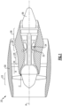
- FIG. 1 schematically illustrates a gas turbine engine 20.
- the example gas turbine engine 20 is a turbofan that generally incorporates a fan section 22, a compressor section 24, a combustor section 26 and a turbine section 28.
- the fan section 22 drives air along a bypass flow path B in a bypass duct defined within a nacelle 30.
- the turbine engine 20 intakes air along a core flow path C into the compressor section 24 for compression and communication into the combustor section 26.
- the compressed air is mixed with fuel from a fuel system 32 and ignited by igniter 34 to generate an exhaust gas flow that expands through the turbine section 28 and is exhausted through exhaust nozzle 36.
- turbofan turbine engine in the disclosed non-limiting embodiment, it should be understood that the concepts described herein are not limited to use with turbofans as the teachings may be applied to other types of turbine engines.
- the propulsor may be an enclosed fan, the propulsor may be an open propeller.
- a gas turbine engine as disclosed in this application will utilize hydrogen (H 2 ) as a fuel.
- H 2 hydrogen
- Challenges are faced by the use of hydrogen, and in particular combustor structure which might be appropriate for aviation fuel may not be as applicable to hydrogen as a fuel.
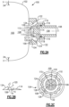
- FIG. 2A shows a combustor 100 having a liner 102 surrounding a fuel and air mixing body 104 and defining a combustion chamber 105.
- the liner 102 is only shown partially.
- Ignitors 34 are shown schematically.
- Fuel is delivered into a central supply passage 106 having a center axis 108.
- a nose 110 is positioned forwardly of the central supply passage 106 and centered on the axis 108.
- Fuel injection passages 114 are spaced circumferentially about the center axis 108, and deliver fuel through outlets 115 downwardly of a nose 110 into an area 112 which is radially inward of a plurality of slots 118/120.
- Air is delivered through holes 116 in an outer sleeve 119 of mixing body 104, and into a slot portion 118 which extends generally parallel to the axis 108. That air then moves into a slot portion 120 where it moves along a forward face 113 of the nose 110 and through outlets 109 along an area 121 forward of an outlet 115 of the fuel injection passages 114. The fuel and air thus begin to mix at this point, and move into the area 112.
- Outer air is delivered into openings 122 in mixing body 104 and a slot 124 which is radially outward of slots 120. That outer air moves along a radially inwardly extending surface 126 of the nose 110. This outer air drives the mixed fuel and air from area 112 into an area 128 where the flame may begin. In this manner, the area 128 where the flame will begin is moved downstream away from the central fuel passage 106. The risk of flame back is thus reduced.
- Figure 2B shows a directional detail of the direction of the fuel injection passages 114 which extend radially away from axis 108 at an angle A.
- the slots 120 extend at an angle B radially toward the axis 108.
- the slots 124 extend along the portion 126 of the nose extend toward the axis 108 an angle C. As can be seen from Figure 2A .
- FIG. 2C shows the slots or passages 120 are circumferentially intermediate the fuel outlets 115. There are a plurality of slots 120 and an equal number of fuel injection passages 114. In this embodiment, there are six of each, however, other numbers can of course be utilized.
- the slot passage 124 can be seen to be circumferentially continuous.
- the fuel and air will be readily mixed and moved toward the area 128 of the combustion chamber 105, and sufficiently downstream of the fuel outlets 115 to reduce the risk of burn back.
- a combustor 100 for a gas turbine engine under this disclosure could be said to include a liner 102 receiving a fuel and air mixing body 104.
- the mixing body has a central fuel passage 106 with a central axis 108 and is adapted to be connected to a source of fuel.
- a nose 110 at a forward end of the central fuel passage includes a plurality of fuel injection passages 114 allowing fuel to flow from the fuel supply passage into an area 112 forward of an outlet 115 from the fuel injection passages.
- An inner air supply is radially outwardly of the central fuel passage to deliver air into inner slots 120 extending downstream of the outlets 115 of the fuel injection passages to an inner slot outlet such that air and fuel can begin to be mixed downstream of an end 113 of the nose. Air from slot 120 prevents recirculation zone formation at end of nose.
- An outer air supply delivers air downstream of the inner air outlet such that air from the outer air supply, air from the inner air slots and fuel from the fuel injection passages are all driven forwardly into a combustion chamber.
- the source of fuel is a source of hydrogen.
- the fuel passages extend from a fuel supply through outlets with an angle A having a component in an axially outward direction and with a radially inward component toward the center axis.
- the outer air passages include a plurality of outer air passages 122 intermediate each of the inner air swirler passages 120.
- the outer air passages include a plurality of outer air passages 122 intermediate each of the inner air swirler passages 120.
- a concentration of air in the inner chamber increases from the central axis to an inner wall defining the inner chamber, and a concentration of fuel in the inner chamber increases from the inner wall to the central axis.
- the fuel passages extend from a fuel supply passage through outlets with an angle A having a component in an axially outward direction and with a radially inward component toward the center axis.
- the outer air passages include a plurality of outer air passages 122 intermediate each of the inner air swirler passages 120.
- the outer air passages include a plurality of outer air passages 122 intermediate each of the inner air swirler passages 120.
- a concentration of air in the inner chamber increases from the central axis to an inner wall defining the inner chamber, and a concentration of fuel in the inner chamber increases from the inner wall to the central axis.
Landscapes
- Engineering & Computer Science (AREA)
- Chemical & Material Sciences (AREA)
- Combustion & Propulsion (AREA)
- Mechanical Engineering (AREA)
- General Engineering & Computer Science (AREA)
- Spray-Type Burners (AREA)
- Pre-Mixing And Non-Premixing Gas Burner (AREA)
Abstract
Description
- This application relates to a combustor for use in a gas turbine engine having central fuel injection and radially outer air injection.
- Gas turbine engines are known, and typically include a compressor delivering compressed air into a combustor. Compressed air is mixed with fuel and ignited. Products of the combustion pass downstream over turbine rotors, driving them to rotate. The turbine rotors in turn rotate the compressor rotor and a propulsor rotor such as a fan or propeller.
- Historically, aviation fuel has been utilized with gas turbine engines, especially for aircraft applications. More recently it has been proposed to utilize hydrogen (H2) as a fuel.
- A combustor for a gas turbine engine according to an aspect of the present invention includes a liner receiving a fuel and air mixing body. The mixing body has a central fuel passage with a central axis and is adapted to be connected to a source of fuel. A nose at a forward (downstream) end of the central fuel passage includes a plurality of fuel injection passages allowing fuel to flow from the central fuel passage into an area forward (downstream) of an outlet from the fuel injection passages. An inner air supply is radially outward of the central fuel passage to deliver air into inner slots extending downstream of the outlets of the fuel injection passages to an inner slot outlet such that air and fuel can begin to be mixed and move downstream of an end of the nose. An outer air supply delivers air downstream of the inner air outlet such that air from the outer air supply, air from the inner slots and fuel from the fuel injection passages are all driven forwardly into a combustion chamber.
- In an embodiment, a fuel supply is connected to the fuel supply passage, and the fuel is hydrogen.
- In a further embodiment according to any of the previous embodiments, the fuel injection passages extend at a first angle radially away from the central axis, the inner slots extend radially at a second angle towards the central axis, and the outer air supply includes at least one outer slot that also extends radially at a third angle toward the central axis, all along an axially downstream direction.
- In a further embodiment according to any of the previous embodiments, the at least one outer slot is a single circumferentially continuous slot.
- In a further embodiment according to any of the previous embodiments, the inner slots are circumferentially intermediate separate ones of said outlets of the fuel passages.
- In a further embodiment according to any of the previous embodiments, an outer sleeve is radially outward of the central fuel passage, and air supply holes extend through said outer sleeve and into the inner slots.
- In a further embodiment according to any of the previous embodiments, the fuel injection passages extend at a first angle radially away from the central axis, the inner slots extend radially at a second angle towards the central axis, and the outer air supply includes at least one slot that also extends radially at a third angle toward the central axis, all along an axially downstream direction.
- A gas turbine engine according to another aspect of the present invention includes a compressor section, a turbine section and a combustor positioned intermediate said compressor section and said turbine section and having a liner receiving a fuel and air mixing body. The mixing body has a central fuel passage with a central axis and is adapted to be connected to a source of fuel. A nose at a forward (downstream) end of the central fuel passage includes a plurality of fuel injection passages allowing fuel to flow from the central fuel passage into an area forward (downstream) of an outlet from the fuel injection passages. An inner air supply is radially outward of the central fuel passage to deliver air into inner slots extending downstream of the outlets of the fuel injection passages to an inner slot outlet such that air and fuel can begin to be mixed and move downstream of an end of the nose. An outer air supply delivers air downstream of the inner air outlet such that air from the outer air supply, air from the inner slots and fuel from the fuel injection passages are all driven forwardly into a combustion chamber.
- In an embodiment, a fuel supply is connected to the fuel supply passage, and the fuel is hydrogen.
- In a further embodiment according to any of the previous embodiments, the fuel injection passages extend at a first angle radially away from the central axis, the inner slots extend radially at a second angle towards the central axis, and the outer air supply includes at least one outer slot that also extends radially at a third angle toward the central axis, all along an axially downstream direction.
- In a further embodiment according to any of the previous embodiments, the at least one outer slot is a single circumferentially continuous slot.
- In a further embodiment according to any of the previous embodiments, the inner slots are circumferentially intermediate separate ones of said outlets of the fuel passages.
- In a further embodiment according to any of the previous embodiments, an outer sleeve is radially outward of the central fuel passage, and air supply holes extend through said outer sleeve and into the inner slots.
- In a further embodiment according to any of the previous embodiments, the fuel injection passages extend at a first angle radially away from the central axis, the inner slots extend radially at a second angle towards the central axis, and the outer air supply includes at least one slot that also extends radially at a third angle toward the central axis, all along an axially downstream direction.
- These and other features will be best understood from the following drawings and specification, the following is a brief description.
-
-
Figure 1 schematically shows a gas turbine engine. -
Figure 2A is a cross-sectional view of a portion of a combustor. -
Figure 2B shows a directional detail of theFigure 2A embodiment. -
Figure 2C is a view of theFigure 2A embodiment looking into a mixing body. -
Figure 1 schematically illustrates agas turbine engine 20. The examplegas turbine engine 20 is a turbofan that generally incorporates afan section 22, acompressor section 24, acombustor section 26 and aturbine section 28. Thefan section 22 drives air along a bypass flow path B in a bypass duct defined within anacelle 30. Theturbine engine 20 intakes air along a core flow path C into thecompressor section 24 for compression and communication into thecombustor section 26. In thecombustor section 26, the compressed air is mixed with fuel from afuel system 32 and ignited byigniter 34 to generate an exhaust gas flow that expands through theturbine section 28 and is exhausted throughexhaust nozzle 36. Although depicted as a turbofan turbine engine in the disclosed non-limiting embodiment, it should be understood that the concepts described herein are not limited to use with turbofans as the teachings may be applied to other types of turbine engines. As one example, rather than having the propulsor be an enclosed fan, the propulsor may be an open propeller. - A gas turbine engine as disclosed in this application will utilize hydrogen (H2) as a fuel. Challenges are faced by the use of hydrogen, and in particular combustor structure which might be appropriate for aviation fuel may not be as applicable to hydrogen as a fuel.
- One challenge when utilizing hydrogen as a fuel is that it is in a gaseous state and more readily flammable than aviation fuel. This could raise challenges with burn back if ignitions starts too close to the fuel feed.
-
Figure 2A shows acombustor 100 having aliner 102 surrounding a fuel andair mixing body 104 and defining acombustion chamber 105. Theliner 102 is only shown partially.Ignitors 34 are shown schematically. - Fuel is delivered into a
central supply passage 106 having acenter axis 108. Anose 110 is positioned forwardly of thecentral supply passage 106 and centered on theaxis 108.Fuel injection passages 114 are spaced circumferentially about thecenter axis 108, and deliver fuel throughoutlets 115 downwardly of anose 110 into anarea 112 which is radially inward of a plurality ofslots 118/120. - Air is delivered through
holes 116 in anouter sleeve 119 ofmixing body 104, and into aslot portion 118 which extends generally parallel to theaxis 108. That air then moves into aslot portion 120 where it moves along aforward face 113 of thenose 110 and throughoutlets 109 along anarea 121 forward of anoutlet 115 of thefuel injection passages 114. The fuel and air thus begin to mix at this point, and move into thearea 112. - Outer air is delivered into
openings 122 in mixingbody 104 and aslot 124 which is radially outward ofslots 120. That outer air moves along a radially inwardly extendingsurface 126 of thenose 110. This outer air drives the mixed fuel and air fromarea 112 into anarea 128 where the flame may begin. In this manner, thearea 128 where the flame will begin is moved downstream away from thecentral fuel passage 106. The risk of flame back is thus reduced. -
Figure 2B shows a directional detail of the direction of thefuel injection passages 114 which extend radially away fromaxis 108 at an angle A. Theslots 120 extend at an angle B radially toward theaxis 108. Theslots 124 extend along theportion 126 of the nose extend toward theaxis 108 an angle C. As can be seen fromFigure 2A . -
Figure 2C shows the slots orpassages 120 are circumferentially intermediate thefuel outlets 115. There are a plurality ofslots 120 and an equal number offuel injection passages 114. In this embodiment, there are six of each, however, other numbers can of course be utilized. - The
slot passage 124 can be seen to be circumferentially continuous. - Now, the fuel and air will be readily mixed and moved toward the
area 128 of thecombustion chamber 105, and sufficiently downstream of thefuel outlets 115 to reduce the risk of burn back. - In a featured embodiment, a
combustor 100 for a gas turbine engine under this disclosure could be said to include aliner 102 receiving a fuel andair mixing body 104. The mixing body has acentral fuel passage 106 with acentral axis 108 and is adapted to be connected to a source of fuel. Anose 110 at a forward end of the central fuel passage includes a plurality offuel injection passages 114 allowing fuel to flow from the fuel supply passage into anarea 112 forward of anoutlet 115 from the fuel injection passages. An inner air supply is radially outwardly of the central fuel passage to deliver air intoinner slots 120 extending downstream of theoutlets 115 of the fuel injection passages to an inner slot outlet such that air and fuel can begin to be mixed downstream of anend 113 of the nose. Air fromslot 120 prevents recirculation zone formation at end of nose. An outer air supply delivers air downstream of the inner air outlet such that air from the outer air supply, air from the inner air slots and fuel from the fuel injection passages are all driven forwardly into a combustion chamber. - In another embodiment according to the previous embodiment, the source of fuel is a source of hydrogen.
- In another embodiment according to any of the previous embodiments, the fuel passages extend from a fuel supply through outlets with an angle A having a component in an axially outward direction and with a radially inward component toward the center axis.
- In another embodiment according to any of the previous embodiments, the outer air passages include a plurality of
outer air passages 122 intermediate each of the inner air swirlerpassages 120. - In another embodiment according to any of the previous embodiments, the outer air passages include a plurality of
outer air passages 122 intermediate each of the inner air swirlerpassages 120. - In another embodiment according to any of the previous embodiments, a concentration of air in the inner chamber increases from the central axis to an inner wall defining the inner chamber, and a concentration of fuel in the inner chamber increases from the inner wall to the central axis.
- In another embodiment according to any of the previous embodiments, the fuel passages extend from a fuel supply passage through outlets with an angle A having a component in an axially outward direction and with a radially inward component toward the center axis.
- In another embodiment according to any of the previous embodiments, the outer air passages include a plurality of
outer air passages 122 intermediate each of the inner air swirlerpassages 120. - In another embodiment according to any of the previous embodiments, the outer air passages include a plurality of
outer air passages 122 intermediate each of the inner air swirlerpassages 120. - In another embodiment according to any of the previous embodiments, a concentration of air in the inner chamber increases from the central axis to an inner wall defining the inner chamber, and a concentration of fuel in the inner chamber increases from the inner wall to the central axis.
- A gas turbine engine incorporating any of the above features is also disclosed and claimed.
- Although embodiments have been disclosed, a worker of skill in this art would recognize that modifications would come within the scope of this disclosure. For that reason, the following claims should be studied to determine the true scope and content of this disclosure.
Claims (8)
- A combustor (100) for a gas turbine engine (20) comprising:a liner (102) receiving a fuel and air mixing body (104), the mixing body (104) having a central fuel passage (106) with a central axis (108) and adapted to be connected to a source of fuel, and a nose (110) at a forward end (113) of the central fuel passage (106), the nose (110) including a plurality of fuel injection passages (114) allowing fuel to flow from the central fuel passage (106) into an area (112) forward of an outlet (115) from the fuel injection passages (114);an inner air supply radially outward of the central fuel passage (106) to deliver air into inner slots (118, 120) extending downstream of the outlets (115) of the fuel injection passages (114) to an inner slot outlet such that air and fuel can begin to be mixed and move downstream of an end (113) of the nose (110); andan outer air supply delivering air downstream of the inner air outlet (115) such that air from the outer air supply, air from the inner slots (118, 120) and fuel from the fuel injection passages (114) are all driven forwardly into a combustion chamber (105).
- The combustor (100) as set forth in claim 1, wherein the fuel injection passages (114) extend at a first angle (A) radially away from the central axis (108), the inner slots (118, 120) extend radially at a second angle (B) towards the central axis (108), and the outer air supply includes at least one outer slot (124) that also extends radially at a third angle (C) toward the central axis (108), all along an axially downstream direction.
- The combustor (100) as set forth in claim 2, wherein the at least one outer slot (124) is a single circumferentially continuous slot.
- The combustor (100) as set forth in claim 2 or 3, wherein the inner slots (118, 120) are circumferentially intermediate separate ones of said outlets (115) of the fuel injection passages (114).
- The combustor (100) as set forth in claim 2, 3 or 4, wherein an outer sleeve (119) is radially outward of the central fuel passage (106), and air supply holes (116) extending through said outer sleeve (119) and into the inner slots (118, 120).
- The combustor (100) as set forth in any preceding claim, wherein a fuel supply is connected to the fuel supply passage (106), and the fuel is hydrogen.
- A gas turbine engine (20) comprising:a compressor section (24) and a turbine section (28); anda combustor (100) as set forth in any of claims 1 to 5 positioned intermediate said compressor section (24) and said turbine section (28).
- The gas turbine engine (20) as set forth in claim 7, wherein a fuel supply is connected to the fuel supply passage (106), and the fuel is hydrogen.
Applications Claiming Priority (1)
| Application Number | Priority Date | Filing Date | Title |
|---|---|---|---|
| US18/104,990 US12111056B2 (en) | 2023-02-02 | 2023-02-02 | Combustor with central fuel injection and downstream air mixing |
Publications (2)
| Publication Number | Publication Date |
|---|---|
| EP4411242A1 true EP4411242A1 (en) | 2024-08-07 |
| EP4411242B1 EP4411242B1 (en) | 2026-04-01 |
Family
ID=89843686
Family Applications (1)
| Application Number | Title | Priority Date | Filing Date |
|---|---|---|---|
| EP24155584.6A Active EP4411242B1 (en) | 2023-02-02 | 2024-02-02 | Combustor with central fuel injection and downstream air mixing |
Country Status (3)
| Country | Link |
|---|---|
| US (1) | US12111056B2 (en) |
| EP (1) | EP4411242B1 (en) |
| CA (1) | CA3223578A1 (en) |
Citations (5)
| Publication number | Priority date | Publication date | Assignee | Title |
|---|---|---|---|---|
| US20070003897A1 (en) * | 2005-06-24 | 2007-01-04 | Hiromi Koizumi | Burner, gas turbine combustor, burner cooling method, and burner modifying method |
| US20120192565A1 (en) * | 2011-01-31 | 2012-08-02 | General Electric Company | System for premixing air and fuel in a fuel nozzle |
| US8973367B2 (en) * | 2008-12-12 | 2015-03-10 | Siemens Aktiengesellschaft | Fuel lance for A burner |
| EP3209941B1 (en) * | 2014-10-20 | 2020-08-19 | Ansaldo Energia S.p.A. | Gas turbine unit with multifluid fuel supply |
| GB2585025A (en) * | 2019-06-25 | 2020-12-30 | Siemens Ag | Combustor for a gas turbine |
Family Cites Families (71)
| Publication number | Priority date | Publication date | Assignee | Title |
|---|---|---|---|---|
| US4070826A (en) * | 1975-12-24 | 1978-01-31 | General Electric Company | Low pressure fuel injection system |
| JPS5635678Y2 (en) | 1978-08-31 | 1981-08-21 | ||
| JPS5926635U (en) | 1982-08-13 | 1984-02-18 | 田中 一郎 | Lower limb body weight foot pressure health device |
| US5404711A (en) * | 1993-06-10 | 1995-04-11 | Solar Turbines Incorporated | Dual fuel injector nozzle for use with a gas turbine engine |
| US5488829A (en) * | 1994-05-25 | 1996-02-06 | Westinghouse Electric Corporation | Method and apparatus for reducing noise generated by combustion |
| US5836163A (en) * | 1996-11-13 | 1998-11-17 | Solar Turbines Incorporated | Liquid pilot fuel injection method and apparatus for a gas turbine engine dual fuel injector |
| US6082113A (en) * | 1998-05-22 | 2000-07-04 | Pratt & Whitney Canada Corp. | Gas turbine fuel injector |
| WO2000019146A2 (en) | 1998-09-24 | 2000-04-06 | Pratt & Whitney Canada Corp. | Fuel spray nozzle |
| US6405523B1 (en) * | 2000-09-29 | 2002-06-18 | General Electric Company | Method and apparatus for decreasing combustor emissions |
| US7603841B2 (en) * | 2001-07-23 | 2009-10-20 | Ramgen Power Systems, Llc | Vortex combustor for low NOx emissions when burning lean premixed high hydrogen content fuel |
| US7003961B2 (en) * | 2001-07-23 | 2006-02-28 | Ramgen Power Systems, Inc. | Trapped vortex combustor |
| US6865889B2 (en) * | 2002-02-01 | 2005-03-15 | General Electric Company | Method and apparatus to decrease combustor emissions |
| US7117678B2 (en) | 2004-04-02 | 2006-10-10 | Pratt & Whitney Canada Corp. | Fuel injector head |
| US8266911B2 (en) | 2005-11-14 | 2012-09-18 | General Electric Company | Premixing device for low emission combustion process |
| US7762073B2 (en) * | 2006-03-01 | 2010-07-27 | General Electric Company | Pilot mixer for mixer assembly of a gas turbine engine combustor having a primary fuel injector and a plurality of secondary fuel injection ports |
| US7762070B2 (en) | 2006-05-11 | 2010-07-27 | Siemens Energy, Inc. | Pilot nozzle heat shield having internal turbulators |
| WO2008097320A2 (en) | 2006-06-01 | 2008-08-14 | Virginia Tech Intellectual Properties, Inc. | Premixing injector for gas turbine engines |
| US20080104961A1 (en) | 2006-11-08 | 2008-05-08 | Ronald Scott Bunker | Method and apparatus for enhanced mixing in premixing devices |
| US7832212B2 (en) | 2006-11-10 | 2010-11-16 | General Electric Company | High expansion fuel injection slot jet and method for enhancing mixing in premixing devices |
| US8099960B2 (en) | 2006-11-17 | 2012-01-24 | General Electric Company | Triple counter rotating swirler and method of use |
| FR2911667B1 (en) * | 2007-01-23 | 2009-10-02 | Snecma Sa | FUEL INJECTION SYSTEM WITH DOUBLE INJECTOR. |
| US8413445B2 (en) | 2007-05-11 | 2013-04-09 | General Electric Company | Method and system for porous flame holder for hydrogen and syngas combustion |
| FR2918716B1 (en) * | 2007-07-12 | 2014-02-28 | Snecma | OPTIMIZATION OF ANTI-COKE FILM IN AN INJECTION SYSTEM |
| US8661779B2 (en) | 2008-09-26 | 2014-03-04 | Siemens Energy, Inc. | Flex-fuel injector for gas turbines |
| FR2941288B1 (en) * | 2009-01-16 | 2011-02-18 | Snecma | DEVICE FOR INJECTING A MIXTURE OF AIR AND FUEL IN A TURBOMACHINE COMBUSTION CHAMBER |
| US8539773B2 (en) | 2009-02-04 | 2013-09-24 | General Electric Company | Premixed direct injection nozzle for highly reactive fuels |
| US20100300102A1 (en) * | 2009-05-28 | 2010-12-02 | General Electric Company | Method and apparatus for air and fuel injection in a turbine |
| JP5898069B2 (en) * | 2009-06-05 | 2016-04-06 | エクソンモービル アップストリーム リサーチ カンパニー | Combustor system and method of use thereof |
| JP5663023B2 (en) * | 2009-09-13 | 2015-02-04 | リーン フレイム インコーポレイテッド | Inlet premixer for combustion equipment |
| EP2299178B1 (en) | 2009-09-17 | 2015-11-04 | Alstom Technology Ltd | A method and gas turbine combustion system for safely mixing H2-rich fuels with air |
| US8794545B2 (en) | 2009-09-25 | 2014-08-05 | General Electric Company | Internal baffling for fuel injector |
| JP5084847B2 (en) | 2010-01-13 | 2012-11-28 | 株式会社日立製作所 | Gas turbine combustor |
| CN103562641B (en) * | 2011-05-17 | 2015-11-25 | 斯奈克玛 | Annular combustors for turbines |
| US8893500B2 (en) * | 2011-05-18 | 2014-11-25 | Solar Turbines Inc. | Lean direct fuel injector |
| JP5630424B2 (en) | 2011-11-21 | 2014-11-26 | 三菱日立パワーシステムズ株式会社 | Gas turbine combustor |
| JP5926635B2 (en) | 2012-07-04 | 2016-05-25 | 三菱日立パワーシステムズ株式会社 | Gas turbine combustor |
| CA2830031C (en) | 2012-10-23 | 2016-03-15 | Alstom Technology Ltd. | Burner for a can combustor |
| FR3003632B1 (en) * | 2013-03-19 | 2016-10-14 | Snecma | INJECTION SYSTEM FOR TURBOMACHINE COMBUSTION CHAMBER HAVING AN ANNULAR WALL WITH CONVERGENT INTERNAL PROFILE |
| CN104075344B (en) | 2013-03-25 | 2016-07-06 | 通用电气公司 | Start and operate fuel nozzle system and the method for gas turbine with low calorie fuels |
| US9909597B2 (en) * | 2013-10-15 | 2018-03-06 | Dresser-Rand Company | Supersonic compressor with separator |
| JP6410924B2 (en) * | 2014-08-14 | 2018-10-24 | シーメンス アクチエンゲゼルシヤフトSiemens Aktiengesellschaft | Multifunctional fuel nozzle with dual orifice atomizer |
| JP6602004B2 (en) | 2014-09-29 | 2019-11-06 | 川崎重工業株式会社 | Fuel injector and gas turbine |
| JP6516996B2 (en) * | 2014-10-10 | 2019-05-22 | 川崎重工業株式会社 | Combustor and gas turbine engine |
| JP2016109309A (en) | 2014-12-02 | 2016-06-20 | 川崎重工業株式会社 | Combustor for gas turbine, and gas turbine |
| JP2016148507A (en) | 2014-12-30 | 2016-08-18 | ゼネラル・エレクトリック・カンパニイ | Pilot nozzle in gas turbine combustor |
| WO2016122529A1 (en) * | 2015-01-29 | 2016-08-04 | Siemens Energy, Inc. | Fuel injector including tandem vanes for injecting alternate fuels in a gas turbine |
| WO2016122521A1 (en) | 2015-01-29 | 2016-08-04 | Siemens Energy, Inc. | Fuel injector including a lobed mixer and vanes for injecting alternate fuels in a gas turbine |
| US20180051883A1 (en) * | 2015-04-01 | 2018-02-22 | Siemens Energy, Inc. | Pre-mixing based fuel nozzle for use in a combustion turbine engine |
| EP3098514A1 (en) | 2015-05-29 | 2016-11-30 | Siemens Aktiengesellschaft | Combustor arrangement |
| CN107735618B (en) | 2015-07-06 | 2020-06-26 | 西门子股份公司 | Combustor for a gas turbine and method of operating a combustor |
| GB201511841D0 (en) * | 2015-07-07 | 2015-08-19 | Rolls Royce Plc | Fuel spray nozel for a gas turbine engine |
| FR3043173B1 (en) * | 2015-10-29 | 2017-12-22 | Snecma | AERODYNAMIC INJECTION SYSTEM FOR AIRCRAFT TURBOMACHINE WITH IMPROVED AIR / FUEL MIXTURE |
| US20170227224A1 (en) | 2016-02-09 | 2017-08-10 | Solar Turbines Incorporated | Fuel injector for combustion engine system, and engine operating method |
| US10234142B2 (en) * | 2016-04-15 | 2019-03-19 | Solar Turbines Incorporated | Fuel delivery methods in combustion engine using wide range of gaseous fuels |
| US9976522B2 (en) | 2016-04-15 | 2018-05-22 | Solar Turbines Incorporated | Fuel injector for combustion engine and staged fuel delivery method |
| US10502425B2 (en) * | 2016-06-03 | 2019-12-10 | General Electric Company | Contoured shroud swirling pre-mix fuel injector assembly |
| US10295190B2 (en) | 2016-11-04 | 2019-05-21 | General Electric Company | Centerbody injector mini mixer fuel nozzle assembly |
| US11149952B2 (en) * | 2016-12-07 | 2021-10-19 | Raytheon Technologies Corporation | Main mixer in an axial staged combustor for a gas turbine engine |
| US11175045B2 (en) * | 2018-01-04 | 2021-11-16 | General Electric Company | Fuel nozzle for gas turbine engine combustor |
| US10941938B2 (en) * | 2018-02-22 | 2021-03-09 | Delavan Inc. | Fuel injectors including gas fuel injection |
| FR3091333B1 (en) * | 2018-12-27 | 2021-05-14 | Safran Aircraft Engines | INJECTOR NOSE FOR TURBOMACHINE INCLUDING A PRIMARY FUEL CIRCUIT ARRANGED AROUND A SECONDARY FUEL CIRCUIT |
| US11506384B2 (en) * | 2019-02-22 | 2022-11-22 | Dyc Turbines | Free-vortex combustor |
| GB2593123A (en) | 2019-06-25 | 2021-09-22 | Siemens Ag | Combustor for a gas turbine |
| JP7200077B2 (en) * | 2019-10-01 | 2023-01-06 | 三菱重工業株式会社 | Gas turbine combustor and its operation method |
| WO2021107616A1 (en) * | 2019-11-25 | 2021-06-03 | 유한회사 플루켐 | Dual-body drug administration device having function of removing mucus from paranasal sinus |
| US11506390B2 (en) | 2019-12-06 | 2022-11-22 | Raytheon Technologies Corporation | Multi-fuel bluff-body piloted high-shear injector and method of using same |
| EP4110540A1 (en) * | 2020-04-03 | 2023-01-04 | Safran Aircraft Engines | Method for additive manufacturing of a wall for a turbine engine, comprising at least one cooling aperture |
| US11808457B2 (en) * | 2021-02-25 | 2023-11-07 | Air Products And Chemicals, Inc. | Hydrogen injection for enhanced combustion stability in gas turbine systems |
| US11692709B2 (en) * | 2021-03-11 | 2023-07-04 | General Electric Company | Gas turbine fuel mixer comprising a plurality of mini tubes for generating a fuel-air mixture |
| US12025311B2 (en) * | 2021-08-24 | 2024-07-02 | Solar Turbines Incorporated | Micromix fuel injection air nozzles |
| US12359813B2 (en) * | 2021-12-29 | 2025-07-15 | General Electric Company | Engine fuel nozzle and swirler |
-
2023
- 2023-02-02 US US18/104,990 patent/US12111056B2/en active Active
- 2023-12-18 CA CA3223578A patent/CA3223578A1/en active Pending
-
2024
- 2024-02-02 EP EP24155584.6A patent/EP4411242B1/en active Active
Patent Citations (5)
| Publication number | Priority date | Publication date | Assignee | Title |
|---|---|---|---|---|
| US20070003897A1 (en) * | 2005-06-24 | 2007-01-04 | Hiromi Koizumi | Burner, gas turbine combustor, burner cooling method, and burner modifying method |
| US8973367B2 (en) * | 2008-12-12 | 2015-03-10 | Siemens Aktiengesellschaft | Fuel lance for A burner |
| US20120192565A1 (en) * | 2011-01-31 | 2012-08-02 | General Electric Company | System for premixing air and fuel in a fuel nozzle |
| EP3209941B1 (en) * | 2014-10-20 | 2020-08-19 | Ansaldo Energia S.p.A. | Gas turbine unit with multifluid fuel supply |
| GB2585025A (en) * | 2019-06-25 | 2020-12-30 | Siemens Ag | Combustor for a gas turbine |
Also Published As
| Publication number | Publication date |
|---|---|
| US12111056B2 (en) | 2024-10-08 |
| US20240263788A1 (en) | 2024-08-08 |
| EP4411242B1 (en) | 2026-04-01 |
| CA3223578A1 (en) | 2025-04-10 |
Similar Documents
| Publication | Publication Date | Title |
|---|---|---|
| CN110966619A (en) | Fuel nozzle | |
| US20180128492A1 (en) | Mini mixing fuel nozzle assembly with mixing sleeve | |
| CA3011124C (en) | Reverse flow combustor | |
| US20110219779A1 (en) | Low emission combustion systems and methods for gas turbine engines | |
| EP4411229A1 (en) | Combustor for gas turbine engine with central fuel injection ports | |
| EP4617568A1 (en) | Cluster of swirled mini-mixers for fuel-staged, axially staged combustion | |
| EP4411244A1 (en) | Combustor with distributed air and fuel mixing | |
| EP4411232A1 (en) | High shear fuel distributor | |
| EP4411242B1 (en) | Combustor with central fuel injection and downstream air mixing | |
| EP4411241A1 (en) | Fuel system with pilot and main injectors for hydrogen-driven gas turbine engine | |
| EP4411225B1 (en) | Combustor with air/fuel mixer creating mixed cloud | |
| EP4411238A1 (en) | Combustor with helix air and fuel mixing passage | |
| EP4411233A1 (en) | Combustor with fuel plenum with mixing passages having baffles | |
| EP4411245B1 (en) | Combustor with fuel and air mixing plenum | |
| EP4411246B1 (en) | Combustor with fuel plenum and extending mixing passages | |
| EP4411237B1 (en) | Injector with disc for hydrogen-driven gas turbine engine | |
| EP4411240A1 (en) | Combined air swirler and fuel distributor | |
| US20250067439A1 (en) | Combustor including a steam injector operably injecting steam inot a trapped vortex cavity |
Legal Events
| Date | Code | Title | Description |
|---|---|---|---|
| PUAI | Public reference made under article 153(3) epc to a published international application that has entered the european phase |
Free format text: ORIGINAL CODE: 0009012 |
|
| STAA | Information on the status of an ep patent application or granted ep patent |
Free format text: STATUS: THE APPLICATION HAS BEEN PUBLISHED |
|
| AK | Designated contracting states |
Kind code of ref document: A1 Designated state(s): AL AT BE BG CH CY CZ DE DK EE ES FI FR GB GR HR HU IE IS IT LI LT LU LV MC ME MK MT NL NO PL PT RO RS SE SI SK SM TR |
|
| STAA | Information on the status of an ep patent application or granted ep patent |
Free format text: STATUS: REQUEST FOR EXAMINATION WAS MADE |
|
| 17P | Request for examination filed |
Effective date: 20250207 |
|
| GRAP | Despatch of communication of intention to grant a patent |
Free format text: ORIGINAL CODE: EPIDOSNIGR1 |
|
| STAA | Information on the status of an ep patent application or granted ep patent |
Free format text: STATUS: GRANT OF PATENT IS INTENDED |
|
| INTG | Intention to grant announced |
Effective date: 20250918 |
|
| GRAS | Grant fee paid |
Free format text: ORIGINAL CODE: EPIDOSNIGR3 |
|
| GRAA | (expected) grant |
Free format text: ORIGINAL CODE: 0009210 |
|
| STAA | Information on the status of an ep patent application or granted ep patent |
Free format text: STATUS: THE PATENT HAS BEEN GRANTED |
|
| AK | Designated contracting states |
Kind code of ref document: B1 Designated state(s): AL AT BE BG CH CY CZ DE DK EE ES FI FR GB GR HR HU IE IS IT LI LT LU LV MC ME MK MT NL NO PL PT RO RS SE SI SK SM TR |
|
| REG | Reference to a national code |
Ref country code: CH Ref legal event code: F10 Free format text: ST27 STATUS EVENT CODE: U-0-0-F10-F00 (AS PROVIDED BY THE NATIONAL OFFICE) Effective date: 20260401 Ref country code: GB Ref legal event code: FG4D |
|
| REG | Reference to a national code |
Ref country code: DE Ref legal event code: R096 Ref document number: 602024003496 Country of ref document: DE |
|
| REG | Reference to a national code |
Ref country code: IE Ref legal event code: FG4D |