EP4411232A1 - High shear fuel distributor - Google Patents
High shear fuel distributor Download PDFInfo
- Publication number
- EP4411232A1 EP4411232A1 EP23220364.6A EP23220364A EP4411232A1 EP 4411232 A1 EP4411232 A1 EP 4411232A1 EP 23220364 A EP23220364 A EP 23220364A EP 4411232 A1 EP4411232 A1 EP 4411232A1
- Authority
- EP
- European Patent Office
- Prior art keywords
- fuel
- inlet
- air
- mixing chamber
- openings
- Prior art date
- Legal status (The legal status is an assumption and is not a legal conclusion. Google has not performed a legal analysis and makes no representation as to the accuracy of the status listed.)
- Withdrawn
Links
Images


Classifications
-
- F—MECHANICAL ENGINEERING; LIGHTING; HEATING; WEAPONS; BLASTING
- F23—COMBUSTION APPARATUS; COMBUSTION PROCESSES
- F23R—GENERATING COMBUSTION PRODUCTS OF HIGH PRESSURE OR HIGH VELOCITY, e.g. GAS-TURBINE COMBUSTION CHAMBERS
- F23R3/00—Continuous combustion chambers using liquid or gaseous fuel
- F23R3/28—Continuous combustion chambers using liquid or gaseous fuel characterised by the fuel supply
- F23R3/286—Continuous combustion chambers using liquid or gaseous fuel characterised by the fuel supply having fuel-air premixing devices
-
- F—MECHANICAL ENGINEERING; LIGHTING; HEATING; WEAPONS; BLASTING
- F02—COMBUSTION ENGINES; HOT-GAS OR COMBUSTION-PRODUCT ENGINE PLANTS
- F02C—GAS-TURBINE PLANTS; AIR INTAKES FOR JET-PROPULSION PLANTS; CONTROLLING FUEL SUPPLY IN AIR-BREATHING JET-PROPULSION PLANTS
- F02C7/00—Features, components parts, details or accessories, not provided for in, or of interest apart form groups F02C1/00 - F02C6/00; Air intakes for jet-propulsion plants
- F02C7/04—Air intakes for gas-turbine plants or jet-propulsion plants
-
- F—MECHANICAL ENGINEERING; LIGHTING; HEATING; WEAPONS; BLASTING
- F02—COMBUSTION ENGINES; HOT-GAS OR COMBUSTION-PRODUCT ENGINE PLANTS
- F02C—GAS-TURBINE PLANTS; AIR INTAKES FOR JET-PROPULSION PLANTS; CONTROLLING FUEL SUPPLY IN AIR-BREATHING JET-PROPULSION PLANTS
- F02C3/00—Gas-turbine plants characterised by the use of combustion products as the working fluid
- F02C3/14—Gas-turbine plants characterised by the use of combustion products as the working fluid characterised by the arrangement of the combustion chamber in the plant
-
- F—MECHANICAL ENGINEERING; LIGHTING; HEATING; WEAPONS; BLASTING
- F02—COMBUSTION ENGINES; HOT-GAS OR COMBUSTION-PRODUCT ENGINE PLANTS
- F02C—GAS-TURBINE PLANTS; AIR INTAKES FOR JET-PROPULSION PLANTS; CONTROLLING FUEL SUPPLY IN AIR-BREATHING JET-PROPULSION PLANTS
- F02C7/00—Features, components parts, details or accessories, not provided for in, or of interest apart form groups F02C1/00 - F02C6/00; Air intakes for jet-propulsion plants
- F02C7/22—Fuel supply systems
- F02C7/222—Fuel flow conduits, e.g. manifolds
-
- F—MECHANICAL ENGINEERING; LIGHTING; HEATING; WEAPONS; BLASTING
- F02—COMBUSTION ENGINES; HOT-GAS OR COMBUSTION-PRODUCT ENGINE PLANTS
- F02C—GAS-TURBINE PLANTS; AIR INTAKES FOR JET-PROPULSION PLANTS; CONTROLLING FUEL SUPPLY IN AIR-BREATHING JET-PROPULSION PLANTS
- F02C7/00—Features, components parts, details or accessories, not provided for in, or of interest apart form groups F02C1/00 - F02C6/00; Air intakes for jet-propulsion plants
- F02C7/22—Fuel supply systems
- F02C7/236—Fuel delivery systems comprising two or more pumps
- F02C7/2365—Fuel delivery systems comprising two or more pumps comprising an air supply system for the atomisation of fuel
-
- F—MECHANICAL ENGINEERING; LIGHTING; HEATING; WEAPONS; BLASTING
- F23—COMBUSTION APPARATUS; COMBUSTION PROCESSES
- F23R—GENERATING COMBUSTION PRODUCTS OF HIGH PRESSURE OR HIGH VELOCITY, e.g. GAS-TURBINE COMBUSTION CHAMBERS
- F23R3/00—Continuous combustion chambers using liquid or gaseous fuel
- F23R3/02—Continuous combustion chambers using liquid or gaseous fuel characterised by the air-flow or gas-flow configuration
- F23R3/04—Air inlet arrangements
- F23R3/10—Air inlet arrangements for primary air
-
- F—MECHANICAL ENGINEERING; LIGHTING; HEATING; WEAPONS; BLASTING
- F23—COMBUSTION APPARATUS; COMBUSTION PROCESSES
- F23R—GENERATING COMBUSTION PRODUCTS OF HIGH PRESSURE OR HIGH VELOCITY, e.g. GAS-TURBINE COMBUSTION CHAMBERS
- F23R3/00—Continuous combustion chambers using liquid or gaseous fuel
- F23R3/02—Continuous combustion chambers using liquid or gaseous fuel characterised by the air-flow or gas-flow configuration
- F23R3/04—Air inlet arrangements
- F23R3/10—Air inlet arrangements for primary air
- F23R3/12—Air inlet arrangements for primary air inducing a vortex
-
- F—MECHANICAL ENGINEERING; LIGHTING; HEATING; WEAPONS; BLASTING
- F23—COMBUSTION APPARATUS; COMBUSTION PROCESSES
- F23R—GENERATING COMBUSTION PRODUCTS OF HIGH PRESSURE OR HIGH VELOCITY, e.g. GAS-TURBINE COMBUSTION CHAMBERS
- F23R2900/00—Special features of, or arrangements for continuous combustion chambers; Combustion processes therefor
- F23R2900/00002—Gas turbine combustors adapted for fuels having low heating value [LHV]
Definitions
- the present disclosure relates to a fuel mixture distributor for a gas turbine engine.
- a gas turbine engine ignites a mixture of compressed air with fuel in a combustor to generate a high temperature exhaust gas flow.
- the exhaust gas flow expands through a turbine to generate shaft power that is utilized to drive a propulsor and engine accessory components.
- Conventional hydrocarbon fuels are introduced into a combustor in a liquid form.
- the liquid fuel is atomized to induce mixing with the compressed airflow.
- Alternate, non-carbon based fuels such as hydrogen perform differently during combustion and therefore unconventional combustor/fuel injection arrangements are necessary to ensure a stable combustion process which delivers the desired turbine inlet temperature pattern, starting and durability while minimizing emissions.
- in order to convert an existing engine design to use alternate fuels it is highly desirable to maintain the existing combustor dimensions. This is particularly important in aviation gas turbine engines, as increases in engine size or weight will have consequences for aircraft design
- Aircraft engine manufacturers continue to seek further improvements to engine performance including improvements to durability, emissions and propulsive efficiencies.
- a fuel mixture distributor for a turbine engine assembly includes a mixing chamber that is disposed about a central axis from a back wall to an outlet to a combustion chamber, and a fuel inlet that extends into the mixing chamber along the central axis.
- the fuel inlet includes a plurality of fuel openings that are angled relative to the central axis.
- the fuel mixture distributor further includes a first air inlet that encircles the mixing chamber and is spaced apart from the fuel inlet.
- the first air inlet includes a plurality of first air openings that introduce a first air flow into the mixing chamber.
- the fuel mixture distributor further includes a second air inlet that is disposed forward of the fuel inlet and the first air inlet. The second air inlet introduces a secondary air flow that is axially forward of the fuel inlet and the first air inlet and proximate to the outlet of the mixing chamber.
- the fuel inlet includes an angled inlet surface and a closed end and the plurality of fuel openings extend through the angled inlet surface.
- the first air openings are disposed at a first axial distance from the back wall and the fuel openings are disposed at a second axial distance from the back wall, the second axial distance is greater than the first axial distance.
- the second air inlet is spaced a third axial distance from the back wall, the third axial distance greater than the first axial distance and the second axial distance.
- the first air openings are disposed at an angle relative to an inner surface of the mixing chamber such that airflow through the first air openings introduces a swirling airflow component within the mixing chamber.
- the second air inlet includes an air conduit that extends between an inlet end spaced a radial distance from an outlet end.
- the inlet end is spaced a radial distance from the central axis greater than a radial distance of the outlet end.
- the air conduit is annular about the central axis.
- the mixing chamber converges from the first air inlet in a direction toward the outlet.
- a combustor assembly for a turbine engine includes, among other possible things, a combustor wall that defines a combustion chamber, and a fuel distributor.
- the fuel distributor includes a mixing chamber that is disposed about a central axis from a back wall to an outlet to the combustion chamber.
- a fuel inlet extends into the mixing chamber along the central axis.
- the fuel inlet includes a plurality of fuel openings angled relative to the central axis.
- a first air inlet includes a plurality of first air openings spaced circumferentially apart around the mixing chamber and spaced apart from the fuel inlet, and a second air inlet is disposed forward of the fuel openings and the first air inlet.
- the plurality of first air openings are each angled relative to an inner surface of the mixing chamber such that airflow through the first air openings introduces a swirling airflow component within the mixing chamber.
- the second air inlet includes an air conduit that extends between an inlet end and an outlet end, the inlet end is spaced a radial distance from the central axis that is greater than a radial distance from the central axis to the outlet end.
- the fuel inlet includes an angled inlet surface and a closed end and the plurality of fuel openings extend through the angled inlet surface.
- the first air openings are disposed at a first axial distance from the back wall
- the fuel openings are disposed at a second axial distance from the back wall
- the second air inlet is spaced a third axial distance from the back wall
- the second axial distance is greater than the first axial distance and the third axial distance greater than either of the first axial distance or the second axial distance.
- the mixing chamber converges from the first air inlet in a direction toward the outlet.
- a turbine engine assembly includes, among other possible things, a compressor section that is in flow series with a turbine section, a combustor assembly including a combustion chamber that is disposed between the compressor section and the turbine section, and a fuel distributor for introducing a fuel air mixture into the combustion chamber.
- the fuel distributor includes a mixing chamber that is disposed about a central axis from a back wall to an outlet to the combustion chamber, a fuel inlet that extends into the mixing chamber along the central axis, the fuel inlet includes a plurality of fuel openings that are angled relative to the central axis, a first air inlet includes a plurality of first air openings that are spaced circumferentially apart around the mixing chamber and spaced apart from the fuel inlet, and a second air inlet that is disposed forward of the fuel openings and the first air openings.
- the turbine engine assembly further includes a fuel system that communicates a fuel in a gaseous phase to the fuel mixture distributor.
- the plurality of first air openings are each angled relative to an inner surface of the mixing chamber such that airflow through the first air openings introduces a swirling airflow component within the mixing chamber.
- the second air inlet includes an air conduit that extends between an inlet end and an outlet end, the inlet end is spaced a radial distance from the central axis that is greater than a radial distance from the central axis of the outlet end.
- the fuel inlet includes an angled inlet surface and a closed end and the plurality of fuel openings extend through the angled inlet surface.
- the mixing chamber converges from the first air inlet in a direction toward the exit opening.
- FIG. 1 schematically illustrates a gas turbine engine 20.
- the example gas turbine engine 20 is a turbofan that generally incorporates a fan section 22, a compressor section 24, a combustor section 26 and a turbine section 28.
- the fan section 22 drives air along a bypass flow path B in a bypass duct defined within a nacelle 30.
- the turbine engine 20 intakes air along a core flow path C into the compressor section 24 for compression and communication into the combustor section 26.
- the compressed air is mixed with fuel from a fuel system 32 and burnt to generate an exhaust gas flow that expands through the turbine section 28 and is exhausted through exhaust nozzle 36.
- An igniter 34 is provided in the combustor section 26 to aid ignition during starting operations.
- turbofan turbine engine in the disclosed non-limiting embodiment, it should be understood that the concepts described herein are not limited to use with turbofans as the teachings may be applied to other types of gas turbine engines.
- the propulsor may be an enclosed fan, the propulsor may be an open propeller.
- hydrocarbon fuels are introduced into a combustor in a liquid form and are atomized to induce mixing with air.
- non-carbon based fuels perform differently during combustion and therefore unconventional combustor/fuel injector arrangements are necessary to ensure a stable combustion process which delivers the desired turbine inlet temperature pattern, starting and durability while minimizing emissions.
- the disclosed example engine is designed to use gaseous hydrogen fuel. While it is possible to introduce hydrogen into the combustor in liquid form, hydrogen is more commonly introduced in a gas phase in turbine combustors in order to maintain stable combustion across the wide range of operating conditions required for an aviation gas turbine.
- the example combustor section 26 includes features tailored to operation using hydrogen fuel including a fuel distributor 38 that induces mixing of the gaseous fuel and air to provide efficient combustion.
- an example combustor assembly 26 is schematically shown and includes walls 44 that define a combustion chamber 46.
- the combustion chamber 46 supports an igniter 34 and includes an exit 48 for combustion gas flow 50.
- a fuel distributor 38 is provided opposite the exit 48 for introducing an air fuel mixture.
- the fuel distributor 38 provides for mixing of a gaseous fuel flow 40 from the fuel system 32 with an airflow 42 prior to entering the combustion chamber 46.
- the air and fuel flows are tailored in conjunction with the combustor holes to provide stable combustion and minimized emissions across the range of engine operating conditions, as well as good starting when ignited by an igniter 34.
- the fuel system 32 provides a gaseous hydrogen fuel flow through a fuel passage 52 into a mixing chamber 54.
- the fuel flow 40 is mixed with air 42.
- the example fuel distributor includes a first air inlet 60 that introduces a first airflow into the mixing chamber and second air inlet 62 that introduces a second airflow.
- the mixing chamber 54 is disposed along a central axis 58 between a back wall 56 and an outlet 72.
- An inlet end 64 of the fuel passage 52 extends through the back wall 56 and into the mixing chamber 54.
- the inlet end 64 includes a closed end face 70 and an angled side surface 66.
- the side surface 66 is a continues surface about the central axis 58.
- Fuel openings 68 are spaced circumferentially about the axis 58 through the side surface 66.
- the angle of the side surface 66 corresponds to an angle at which the fuel openings 68 are arranged relative to the central axis 58
- the fuel openings 68 are disposed axially forward of the first air inlet 60. Accordingly, air flow from the first inlet 60 is introduced upstream of the fuel openings 68.
- a second air inlet 62 is disposed forward and downstream of the first air inlet 60 and communicates a second airflow through a conduit 80 to a location proximate the outlet 72 to the combustion chamber 46.
- the second air inlet 62 includes an inlet end 76 spaced radially a distance 92 from the central axis 58.
- An outlet end 78 is spaced radially a distance 94 from the central axis 58 that is less than the distance 92.
- the conduit 80 slants inwardly toward the central axis from the inlet end 76 to define a generally converging inner surface 74 of the mixing chamber 54 in the direction toward the outlet 72.
- the first airflow through the first air inlet 60 is introduced into the mixing chamber 54 aft and upstream of the fuel openings 68.
- the first air inlet 60 provides a swirling flow about the inlet end 64 as the flow moves forward toward the outlet 72.
- Fuel flow 40 introduced through the fuel passages 68 is angled outwardly and forward toward the outlet 72.
- the swirling air flow from the first air inlet 60 combines with the forward and outward flow direction of fuel through the fuel openings 68 to induce mixing to form a desired air fuel mixture.
- an additional amount of air flow is introduced through the second air inlet 62.
- the inward angled conduit 80 of the second air inlet 62 provides additional momentum for the fuel air mixture into the combustion chamber 46 as well as additional air flow to provide a desired stoichiometric mix of air and fuel.
- the converging structure of the mixing chamber 54 further provides an increase in flow momentum to propel the fuel air mixture into the combustion chamber 46.
- the first air inlet 60 is disposed within a plane 96.
- the plane 96 is spaced axially apart from the back wall a distance 102.
- the fuel openings 68 are disposed in a plane 98 spaced axially apart from the back wall 56 a distance 104.
- the outlet end 78 of the second air inlet 62 is disposed within a plane 100 that is spaced an axial distance 106 from the back wall 56.
- Each of the planes 96, 98 and 100 are transverse to the central axis 58. The incremental and different spacing of the fuel and air inlets encourages a complete mixing of fuel and air.
- the plane 96 of the first air inlet 60 is disposed upstream of the plane 98 that includes the fuel openings 68.
- the plane 100 is downstream of both the planes 96 and 98 and introduces a second airflow further downstream and proximate the outlet 72.
- the first air inlet 60 includes a plurality of air passages 82 that extend through a wall 108 about an individual passage axis 84.
- the passage axis 84 is disposed at an angle 90 relative to a line 88 tangent with an outer surface 86 of the wall 108.
- the angle 90 is a non-normal angle and provides for the airflow 42 to enter the mixing chamber 54 in a manner that induces a swirling and mixing flow.
- the air passages 82 are arranged about a circumference of the wall 108 and may be of any size or shape defined to provide a desired magnitude of airflow intended to generate the swirling flow for generating a desired air fuel mixture. Moreover, although four air passages 82 are shown by way of example, any number of air passages 82 could be utilized and remain within the scope and contemplation of this disclosure.
- a front portion of the example fuel distributor 38 is shown looking from the combustor exit 48 toward the fuel distributor 38.
- the exit end 78 is shown as an annular opening disposed about the central axis 58.
- the exit end 78 is disposed about the outlet 72 of the mixing chamber 54 to introduce additional air and to propel the fuel air mixture into the combustion chamber 46.
- the closed end 70 of the fuel inlet 64 can be seen centered within the outlet 72.
- the inlet end 76 of the second air inlet 62 is also shown to indicate where air flow is directed into the conduit 80.
- the outer surface of the conduit 80 is shown in this view between the inlet end 76 and the outlet end 78.
- the inlet end 76 may also be an annular opening as shown.
- the inlet end 76 and the outlet end 78 are shown as full annular openings, the openings may be segmented or otherwise divided. Moreover, the openings in the inlet end 76 and the outlet end 78 may be a provided by a plurality of passages spaced circumferentially apart about the central axis 58.
- the example fuel distributor 38 is operated at a stochiometric range of between 0.5 and 2.
- the size and number of first and second air inlets 60, 62, the size and shape of the mixing chamber 54 and fuel openings 68 may be adjusted to provide the desired stochiometric mixture of fuel and air communicated into the combustion chamber 46.
- the example disclosed fuel distributor 38 provides mixing of air and gaseous fuel prior to being introduced into the combustion chamber 46. Additionally, the example fuel distributor 38 induces a swirling flow in the fuel air mixture to aid in distribution upon entering the combustion chamber 46 to improve combustion operation and efficiency.
- a fuel mixture distributor 38 for a turbine engine assembly includes, among other possible things, a mixing chamber 54 that is disposed about a central axis 58 from a back wall 56 to an outlet 72 of a combustion chamber 46, and a fuel inlet 64 that extends into the mixing chamber 54 along the central axis 58.
- the fuel inlet 64 includes a plurality of fuel openings 68 that are angled relative to the central axis 58.
- the fuel mixture distributor 38 further includes a first air inlet 60 that encircles the mixing chamber 54 and is spaced apart from the fuel inlet 64.
- the first air inlet 60 includes a plurality of first air openings 82 that introduce a first air flow 42 into the mixing chamber 54.
- the fuel mixture distributor 38 further includes a second air inlet 62 that is disposed forward of the fuel inlet 64 and the first air inlet 60.
- the second air inlet 62 introduces a secondary air flow that is axially forward of the fuel inlet 64 and the first air inlet 60 and proximate to the outlet 72 of the mixing chamber 54.
- the fuel inlet 64 includes an angled inlet surface 66 and a closed end 70 and the plurality of fuel openings 68 extend through the angled inlet surface 66.
- the first air openings 82 are disposed at a first axial distance from the back wall 56 and the fuel openings 68 are disposed at a second axial distance from the back wall 56.
- the second axial distance is greater than the first axial distance.
- the second air inlet 62 is spaced a third axial distance from the back wall 56.
- the third axial distance is greater than the first axial distance and the second axial distance.
- the first air openings 82 are disposed at an angle relative to an inner surface of the mixing chamber 54 such that airflow through the first air openings introduces a swirling airflow component within the mixing chamber 54.
- the second air inlet 62 includes an air conduit 80 that extends between an inlet end 76 spaced a radial distance from an outlet end 78.
- the inlet end 76 is spaced a radial distance from the central axis 58 greater than a radial distance of the outlet end 78.
- the air conduit 80 is annular about the central axis 58.
- the mixing chamber 54 converges from the first air inlet 60 in a direction toward the outlet 72.
- a combustor assembly 26 for a turbine engine includes a combustor wall 44 that defines a combustion chamber 46, and a fuel distributor 38.
- the fuel distributor 38 includes a mixing chamber 54 that is disposed about a central axis 58 from a back wall 56 to an outlet 72 to the combustion chamber 46.
- a fuel inlet 64 extends into the mixing chamber 54 along the central axis 58.
- the fuel inlet includes a plurality of fuel openings that are angled relative to the central axis.
- a first air inlet 60 includes a plurality of first air openings 82 that are spaced circumferentially apart around the mixing chamber 54 and spaced apart from the fuel inlet 64, and a second air inlet 62 is disposed forward of the fuel openings 68 and the first air inlet 60.
- the plurality of first air openings 82 are each angled relative to an inner surface of the mixing chamber 54 such that airflow through the first air openings 82 introduces a swirling airflow component within the mixing chamber 54.
- the second air inlet 62 includes an air conduit 80 that extends between an inlet end 64 and an outlet end 78.
- the inlet end 64 is spaced a radial distance from the central axis 58 that is greater than a radial distance from the central axis 58 to the outlet end 78.
- the fuel inlet 64 includes an angled inlet surface 66 and a closed end 70 and the plurality of fuel openings 68 extend through the angled inlet surface 66.
- the first air openings 82 are disposed at a first axial distance from the back wall 56
- the fuel openings 68 are disposed at a second axial distance from the back wall 56
- the second air inlet 62 is spaced a third axial distance from the back wall 56.
- the second axial distance is greater than the first axial distance and the third axial distance greater than either of the first axial distance or the second axial distance.
- the mixing chamber 54 converges from the first air inlet 60 in a direction toward the outlet 72.
- a turbine engine assembly 20 includes, among other possible things, a compressor section 24 that is in flow series with a turbine section 28, a combustor assembly 26 including a combustion chamber 46 that is disposed between the compressor section 24 and the turbine section 28, and a fuel distributor 38 for introducing a fuel air mixture into the combustion chamber 46.
- the fuel distributor 38 includes a mixing chamber 54 that is disposed about a central axis 58 from a back wall 56 to an outlet 72 to the combustion chamber 46, a fuel inlet 64 that extends into the mixing chamber 54 along the central axis 58, the fuel inlet 64 includes a plurality of fuel openings 68 that are angled relative to the central axis 58, a first air inlet 60 includes a plurality of first air openings 82 that are spaced circumferentially apart around the mixing chamber 54 and spaced apart from the fuel inlet 64, and a second air inlet 62 that is disposed forward of the fuel openings 68 and the first air openings 82.
- the turbine engine assembly 20 further includes a fuel system 32 that communicates a fuel in a gaseous phase to the fuel mixture distributor 38.
- the plurality of first air openings 82 are each angled relative to an inner surface of the mixing chamber 54 such that airflow through the first air openings 82 introduces a swirling airflow component within the mixing chamber 54.
- the second air inlet 62 includes an air conduit 80 that extends between an inlet end 76 and an outlet end 78.
- the inlet end 76 is spaced a radial distance from the central axis 58 that is greater than a radial distance from the central axis 58 of the outlet end 78.
- the fuel inlet 64 includes an angled inlet surface 66 and a closed end 70 and the plurality of fuel openings 68 extend through the angled inlet surface 66.
- the mixing chamber 54 converges from the first air inlet 60 in a direction toward the exit opening 72.
Landscapes
- Engineering & Computer Science (AREA)
- Chemical & Material Sciences (AREA)
- Combustion & Propulsion (AREA)
- Mechanical Engineering (AREA)
- General Engineering & Computer Science (AREA)
- Combustion Methods Of Internal-Combustion Engines (AREA)
Abstract
Description
- The present disclosure relates to a fuel mixture distributor for a gas turbine engine.
- A gas turbine engine ignites a mixture of compressed air with fuel in a combustor to generate a high temperature exhaust gas flow. The exhaust gas flow expands through a turbine to generate shaft power that is utilized to drive a propulsor and engine accessory components. Conventional hydrocarbon fuels are introduced into a combustor in a liquid form. The liquid fuel is atomized to induce mixing with the compressed airflow. Alternate, non-carbon based fuels such as hydrogen perform differently during combustion and therefore unconventional combustor/fuel injection arrangements are necessary to ensure a stable combustion process which delivers the desired turbine inlet temperature pattern, starting and durability while minimizing emissions. At the same time, in order to convert an existing engine design to use alternate fuels it is highly desirable to maintain the existing combustor dimensions. This is particularly important in aviation gas turbine engines, as increases in engine size or weight will have consequences for aircraft design
- Aircraft engine manufacturers continue to seek further improvements to engine performance including improvements to durability, emissions and propulsive efficiencies.
- A fuel mixture distributor for a turbine engine assembly according to an aspect of the present invention includes a mixing chamber that is disposed about a central axis from a back wall to an outlet to a combustion chamber, and a fuel inlet that extends into the mixing chamber along the central axis. The fuel inlet includes a plurality of fuel openings that are angled relative to the central axis. The fuel mixture distributor further includes a first air inlet that encircles the mixing chamber and is spaced apart from the fuel inlet. The first air inlet includes a plurality of first air openings that introduce a first air flow into the mixing chamber. The fuel mixture distributor further includes a second air inlet that is disposed forward of the fuel inlet and the first air inlet. The second air inlet introduces a secondary air flow that is axially forward of the fuel inlet and the first air inlet and proximate to the outlet of the mixing chamber.
- In an embodiment, the fuel inlet includes an angled inlet surface and a closed end and the plurality of fuel openings extend through the angled inlet surface.
- In a further embodiment of any of the previous embodiments, the first air openings are disposed at a first axial distance from the back wall and the fuel openings are disposed at a second axial distance from the back wall, the second axial distance is greater than the first axial distance.
- In a further embodiment of any of the previous embodiments, the second air inlet is spaced a third axial distance from the back wall, the third axial distance greater than the first axial distance and the second axial distance.
- In a further embodiment of any of the previous embodiments, the first air openings are disposed at an angle relative to an inner surface of the mixing chamber such that airflow through the first air openings introduces a swirling airflow component within the mixing chamber.
- In a further embodiment of any of the previous embodiments, the second air inlet includes an air conduit that extends between an inlet end spaced a radial distance from an outlet end.
- In a further embodiment of any of the previous embodiments, the inlet end is spaced a radial distance from the central axis greater than a radial distance of the outlet end.
- In a further embodiment of any of the previous embodiments, the air conduit is annular about the central axis.
- In a further embodiment of any of the previous embodiments, the mixing chamber converges from the first air inlet in a direction toward the outlet.
- A combustor assembly for a turbine engine according to another disclosed example embodiment includes, among other possible things, a combustor wall that defines a combustion chamber, and a fuel distributor. The fuel distributor includes a mixing chamber that is disposed about a central axis from a back wall to an outlet to the combustion chamber. A fuel inlet extends into the mixing chamber along the central axis. The fuel inlet includes a plurality of fuel openings angled relative to the central axis. A first air inlet includes a plurality of first air openings spaced circumferentially apart around the mixing chamber and spaced apart from the fuel inlet, and a second air inlet is disposed forward of the fuel openings and the first air inlet.
- In an embodiment, the plurality of first air openings are each angled relative to an inner surface of the mixing chamber such that airflow through the first air openings introduces a swirling airflow component within the mixing chamber.
- In a further embodiment of any of the previous embodiments, the second air inlet includes an air conduit that extends between an inlet end and an outlet end, the inlet end is spaced a radial distance from the central axis that is greater than a radial distance from the central axis to the outlet end.
- In a further embodiment of any of the previous embodiments, the fuel inlet includes an angled inlet surface and a closed end and the plurality of fuel openings extend through the angled inlet surface.
- In a further embodiment of any of the previous embodiments, the first air openings are disposed at a first axial distance from the back wall, the fuel openings are disposed at a second axial distance from the back wall, and the second air inlet is spaced a third axial distance from the back wall, the second axial distance is greater than the first axial distance and the third axial distance greater than either of the first axial distance or the second axial distance.
- In a further embodiment of any of the previous embodiments, the mixing chamber converges from the first air inlet in a direction toward the outlet.
- A turbine engine assembly according to another disclosed example embodiment includes, among other possible things, a compressor section that is in flow series with a turbine section, a combustor assembly including a combustion chamber that is disposed between the compressor section and the turbine section, and a fuel distributor for introducing a fuel air mixture into the combustion chamber. The fuel distributor includes a mixing chamber that is disposed about a central axis from a back wall to an outlet to the combustion chamber, a fuel inlet that extends into the mixing chamber along the central axis, the fuel inlet includes a plurality of fuel openings that are angled relative to the central axis, a first air inlet includes a plurality of first air openings that are spaced circumferentially apart around the mixing chamber and spaced apart from the fuel inlet, and a second air inlet that is disposed forward of the fuel openings and the first air openings. The turbine engine assembly further includes a fuel system that communicates a fuel in a gaseous phase to the fuel mixture distributor.
- In an embodiment, the plurality of first air openings are each angled relative to an inner surface of the mixing chamber such that airflow through the first air openings introduces a swirling airflow component within the mixing chamber.
- In a further embodiment of any of the previous embodiments, the second air inlet includes an air conduit that extends between an inlet end and an outlet end, the inlet end is spaced a radial distance from the central axis that is greater than a radial distance from the central axis of the outlet end.
- In a further embodiment of any of the previous embodiments, the fuel inlet includes an angled inlet surface and a closed end and the plurality of fuel openings extend through the angled inlet surface.
- In a further embodiment of any of the previous embodiments, the mixing chamber converges from the first air inlet in a direction toward the exit opening.
- Although the different examples have the specific components shown in the illustrations, embodiments of this disclosure are not limited to those particular combinations. It is possible to use some of the components or features from one of the examples in combination with features or components from another one of the examples.
- These and other features disclosed herein can be best understood from the following specification and drawings, the following of which is a brief description.
-
-
Figure 1 is a schematic view of an example turbine engine including a fuel distributor for introducing a fuel air mixture into a combustion chamber -
Figure 2 is a schematic view of an example combustor assembly embodiment. -
Figure 3 is an enlarged schematic view of an example fuel distributor embodiment. -
Figure 4 is a cross-sectional view of a portion of the example fuel distributor embodiment. -
Figure 5 is a front view of the example fuel distributor embodiment. -
Figure 1 schematically illustrates agas turbine engine 20. The examplegas turbine engine 20 is a turbofan that generally incorporates afan section 22, acompressor section 24, acombustor section 26 and aturbine section 28. Thefan section 22 drives air along a bypass flow path B in a bypass duct defined within anacelle 30. Theturbine engine 20 intakes air along a core flow path C into thecompressor section 24 for compression and communication into thecombustor section 26. In thecombustor section 26, the compressed air is mixed with fuel from afuel system 32 and burnt to generate an exhaust gas flow that expands through theturbine section 28 and is exhausted throughexhaust nozzle 36. Anigniter 34 is provided in thecombustor section 26 to aid ignition during starting operations. - Although depicted as a turbofan turbine engine in the disclosed non-limiting embodiment, it should be understood that the concepts described herein are not limited to use with turbofans as the teachings may be applied to other types of gas turbine engines. As one example, rather than having the propulsor be an enclosed fan, the propulsor may be an open propeller.
- Conventional hydrocarbon fuels are introduced into a combustor in a liquid form and are atomized to induce mixing with air. Alternative, non-carbon based fuels perform differently during combustion and therefore unconventional combustor/fuel injector arrangements are necessary to ensure a stable combustion process which delivers the desired turbine inlet temperature pattern, starting and durability while minimizing emissions. The disclosed example engine is designed to use gaseous hydrogen fuel. While it is possible to introduce hydrogen into the combustor in liquid form, hydrogen is more commonly introduced in a gas phase in turbine combustors in order to maintain stable combustion across the wide range of operating conditions required for an aviation gas turbine. As a gaseous fuel, hydrogen has a wider range of flammability and a higher flame velocity than conventional liquid fuels used in gas turbine engines, this results in changes in the flame pattern within the combustor which may influence the engine durability, starting, or emissions. Accordingly, the
example combustor section 26 includes features tailored to operation using hydrogen fuel including afuel distributor 38 that induces mixing of the gaseous fuel and air to provide efficient combustion. - Referring to
Figure 2 , anexample combustor assembly 26 is schematically shown and includeswalls 44 that define acombustion chamber 46. Thecombustion chamber 46 supports anigniter 34 and includes anexit 48 forcombustion gas flow 50. Afuel distributor 38 is provided opposite theexit 48 for introducing an air fuel mixture. Thefuel distributor 38 provides for mixing of agaseous fuel flow 40 from thefuel system 32 with anairflow 42 prior to entering thecombustion chamber 46. The air and fuel flows are tailored in conjunction with the combustor holes to provide stable combustion and minimized emissions across the range of engine operating conditions, as well as good starting when ignited by anigniter 34. In one disclosed example, thefuel system 32 provides a gaseous hydrogen fuel flow through afuel passage 52 into a mixingchamber 54. In the mixingchamber 54, thefuel flow 40 is mixed withair 42. The example fuel distributor includes afirst air inlet 60 that introduces a first airflow into the mixing chamber andsecond air inlet 62 that introduces a second airflow. - Referring to
Figure 3 , with continued reference toFigure 2 , the mixingchamber 54 is disposed along acentral axis 58 between aback wall 56 and anoutlet 72. Aninlet end 64 of thefuel passage 52 extends through theback wall 56 and into the mixingchamber 54. Theinlet end 64 includes aclosed end face 70 and anangled side surface 66. Theside surface 66 is a continues surface about thecentral axis 58.Fuel openings 68 are spaced circumferentially about theaxis 58 through theside surface 66. The angle of theside surface 66 corresponds to an angle at which thefuel openings 68 are arranged relative to thecentral axis 58 - The
fuel openings 68 are disposed axially forward of thefirst air inlet 60. Accordingly, air flow from thefirst inlet 60 is introduced upstream of thefuel openings 68. Asecond air inlet 62 is disposed forward and downstream of thefirst air inlet 60 and communicates a second airflow through aconduit 80 to a location proximate theoutlet 72 to thecombustion chamber 46. Thesecond air inlet 62 includes aninlet end 76 spaced radially adistance 92 from thecentral axis 58. Anoutlet end 78 is spaced radially adistance 94 from thecentral axis 58 that is less than thedistance 92. Theconduit 80 slants inwardly toward the central axis from theinlet end 76 to define a generally converginginner surface 74 of the mixingchamber 54 in the direction toward theoutlet 72. - The first airflow through the
first air inlet 60 is introduced into the mixingchamber 54 aft and upstream of thefuel openings 68. Thefirst air inlet 60 provides a swirling flow about theinlet end 64 as the flow moves forward toward theoutlet 72.Fuel flow 40 introduced through thefuel passages 68 is angled outwardly and forward toward theoutlet 72. The swirling air flow from thefirst air inlet 60 combines with the forward and outward flow direction of fuel through thefuel openings 68 to induce mixing to form a desired air fuel mixture. As the fuel air mixture proceeds through the mixingchamber 54 toward theoutlet 72, an additional amount of air flow is introduced through thesecond air inlet 62. The inwardangled conduit 80 of thesecond air inlet 62 provides additional momentum for the fuel air mixture into thecombustion chamber 46 as well as additional air flow to provide a desired stoichiometric mix of air and fuel. The converging structure of the mixingchamber 54 further provides an increase in flow momentum to propel the fuel air mixture into thecombustion chamber 46. - The
first air inlet 60 is disposed within aplane 96. Theplane 96 is spaced axially apart from the back wall adistance 102. Thefuel openings 68 are disposed in aplane 98 spaced axially apart from the back wall 56 adistance 104. Theoutlet end 78 of thesecond air inlet 62 is disposed within aplane 100 that is spaced anaxial distance 106 from theback wall 56. Each of theplanes central axis 58. The incremental and different spacing of the fuel and air inlets encourages a complete mixing of fuel and air. In one example embodiment, theplane 96 of thefirst air inlet 60 is disposed upstream of theplane 98 that includes thefuel openings 68. Theplane 100 is downstream of both theplanes outlet 72. - Referring to
Figure 4 , with continued reference toFigure 3 , thefirst air inlet 60 includes a plurality ofair passages 82 that extend through awall 108 about anindividual passage axis 84. Thepassage axis 84 is disposed at anangle 90 relative to aline 88 tangent with anouter surface 86 of thewall 108. Theangle 90 is a non-normal angle and provides for theairflow 42 to enter the mixingchamber 54 in a manner that induces a swirling and mixing flow. - The
air passages 82 are arranged about a circumference of thewall 108 and may be of any size or shape defined to provide a desired magnitude of airflow intended to generate the swirling flow for generating a desired air fuel mixture. Moreover, although fourair passages 82 are shown by way of example, any number ofair passages 82 could be utilized and remain within the scope and contemplation of this disclosure. - Referring to
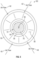
Figure 5 , with continued reference toFigure 3 , a front portion of theexample fuel distributor 38 is shown looking from thecombustor exit 48 toward thefuel distributor 38. Theexit end 78 is shown as an annular opening disposed about thecentral axis 58. Theexit end 78 is disposed about theoutlet 72 of the mixingchamber 54 to introduce additional air and to propel the fuel air mixture into thecombustion chamber 46. Theclosed end 70 of thefuel inlet 64 can be seen centered within theoutlet 72. Theinlet end 76 of thesecond air inlet 62 is also shown to indicate where air flow is directed into theconduit 80. The outer surface of theconduit 80 is shown in this view between theinlet end 76 and theoutlet end 78. Theinlet end 76 may also be an annular opening as shown. Although theinlet end 76 and theoutlet end 78 are shown as full annular openings, the openings may be segmented or otherwise divided. Moreover, the openings in theinlet end 76 and theoutlet end 78 may be a provided by a plurality of passages spaced circumferentially apart about thecentral axis 58. - The
example fuel distributor 38 is operated at a stochiometric range of between 0.5 and 2. The size and number of first andsecond air inlets chamber 54 andfuel openings 68 may be adjusted to provide the desired stochiometric mixture of fuel and air communicated into thecombustion chamber 46. - The example disclosed
fuel distributor 38 provides mixing of air and gaseous fuel prior to being introduced into thecombustion chamber 46. Additionally, theexample fuel distributor 38 induces a swirling flow in the fuel air mixture to aid in distribution upon entering thecombustion chamber 46 to improve combustion operation and efficiency. - A
fuel mixture distributor 38 for a turbine engine assembly according to one example disclosed embodiment includes, among other possible things, a mixingchamber 54 that is disposed about acentral axis 58 from aback wall 56 to anoutlet 72 of acombustion chamber 46, and afuel inlet 64 that extends into the mixingchamber 54 along thecentral axis 58. Thefuel inlet 64 includes a plurality offuel openings 68 that are angled relative to thecentral axis 58. Thefuel mixture distributor 38 further includes afirst air inlet 60 that encircles the mixingchamber 54 and is spaced apart from thefuel inlet 64. Thefirst air inlet 60 includes a plurality offirst air openings 82 that introduce afirst air flow 42 into the mixingchamber 54. Thefuel mixture distributor 38 further includes asecond air inlet 62 that is disposed forward of thefuel inlet 64 and thefirst air inlet 60. Thesecond air inlet 62 introduces a secondary air flow that is axially forward of thefuel inlet 64 and thefirst air inlet 60 and proximate to theoutlet 72 of the mixingchamber 54. - In a further embodiment of the foregoing, the
fuel inlet 64 includes anangled inlet surface 66 and aclosed end 70 and the plurality offuel openings 68 extend through theangled inlet surface 66. - In a further embodiment of any of the foregoing, the
first air openings 82 are disposed at a first axial distance from theback wall 56 and thefuel openings 68 are disposed at a second axial distance from theback wall 56. The second axial distance is greater than the first axial distance. - In a further embodiment of any of the foregoing, the
second air inlet 62 is spaced a third axial distance from theback wall 56. The third axial distance is greater than the first axial distance and the second axial distance. - In a further embodiment of any of the foregoing, the
first air openings 82 are disposed at an angle relative to an inner surface of the mixingchamber 54 such that airflow through the first air openings introduces a swirling airflow component within the mixingchamber 54. - In a further embodiment of any of the foregoing, the
second air inlet 62 includes anair conduit 80 that extends between aninlet end 76 spaced a radial distance from anoutlet end 78. - In a further embodiment of any of the foregoing, the
inlet end 76 is spaced a radial distance from thecentral axis 58 greater than a radial distance of theoutlet end 78. - In a further embodiment of any of the foregoing, the
air conduit 80 is annular about thecentral axis 58. - In a further embodiment of any of the foregoing, the mixing
chamber 54 converges from thefirst air inlet 60 in a direction toward theoutlet 72. - A
combustor assembly 26 for a turbine engine according to another exemplary embodiment of this disclosure, among other possible things includes acombustor wall 44 that defines acombustion chamber 46, and afuel distributor 38. Thefuel distributor 38 includes a mixingchamber 54 that is disposed about acentral axis 58 from aback wall 56 to anoutlet 72 to thecombustion chamber 46. Afuel inlet 64 extends into the mixingchamber 54 along thecentral axis 58. The fuel inlet includes a plurality of fuel openings that are angled relative to the central axis. Afirst air inlet 60 includes a plurality offirst air openings 82 that are spaced circumferentially apart around the mixingchamber 54 and spaced apart from thefuel inlet 64, and asecond air inlet 62 is disposed forward of thefuel openings 68 and thefirst air inlet 60. - In a further embodiment of the foregoing, the plurality of
first air openings 82 are each angled relative to an inner surface of the mixingchamber 54 such that airflow through thefirst air openings 82 introduces a swirling airflow component within the mixingchamber 54. - In a further embodiment of any of the foregoing, the
second air inlet 62 includes anair conduit 80 that extends between aninlet end 64 and anoutlet end 78. Theinlet end 64 is spaced a radial distance from thecentral axis 58 that is greater than a radial distance from thecentral axis 58 to theoutlet end 78. - In a further embodiment of any of the foregoing, the
fuel inlet 64 includes anangled inlet surface 66 and aclosed end 70 and the plurality offuel openings 68 extend through theangled inlet surface 66. - In a further embodiment of any of the foregoing, the
first air openings 82 are disposed at a first axial distance from theback wall 56, thefuel openings 68 are disposed at a second axial distance from theback wall 56, and thesecond air inlet 62 is spaced a third axial distance from theback wall 56. The second axial distance is greater than the first axial distance and the third axial distance greater than either of the first axial distance or the second axial distance. - In a further embodiment of any of the foregoing, the mixing
chamber 54 converges from thefirst air inlet 60 in a direction toward theoutlet 72. - A
turbine engine assembly 20 according to another disclosed example embodiment includes, among other possible things, acompressor section 24 that is in flow series with aturbine section 28, acombustor assembly 26 including acombustion chamber 46 that is disposed between thecompressor section 24 and theturbine section 28, and afuel distributor 38 for introducing a fuel air mixture into thecombustion chamber 46. Thefuel distributor 38 includes a mixingchamber 54 that is disposed about acentral axis 58 from aback wall 56 to anoutlet 72 to thecombustion chamber 46, afuel inlet 64 that extends into the mixingchamber 54 along thecentral axis 58, thefuel inlet 64 includes a plurality offuel openings 68 that are angled relative to thecentral axis 58, afirst air inlet 60 includes a plurality offirst air openings 82 that are spaced circumferentially apart around the mixingchamber 54 and spaced apart from thefuel inlet 64, and asecond air inlet 62 that is disposed forward of thefuel openings 68 and thefirst air openings 82. Theturbine engine assembly 20 further includes afuel system 32 that communicates a fuel in a gaseous phase to thefuel mixture distributor 38. - In a further embodiment of the foregoing, the plurality of
first air openings 82 are each angled relative to an inner surface of the mixingchamber 54 such that airflow through thefirst air openings 82 introduces a swirling airflow component within the mixingchamber 54. - In a further embodiment of any of the foregoing, the
second air inlet 62 includes anair conduit 80 that extends between aninlet end 76 and anoutlet end 78. Theinlet end 76 is spaced a radial distance from thecentral axis 58 that is greater than a radial distance from thecentral axis 58 of theoutlet end 78. - In a further embodiment of any of the foregoing, the
fuel inlet 64 includes anangled inlet surface 66 and aclosed end 70 and the plurality offuel openings 68 extend through theangled inlet surface 66. - In a further embodiment of any of the foregoing, the mixing
chamber 54 converges from thefirst air inlet 60 in a direction toward theexit opening 72. - Although an example embodiment has been disclosed, a worker of ordinary skill in this art would recognize that certain modifications would come within the scope of this disclosure. For that reason, the following claims should be studied to determine the scope and content of this disclosure.
Claims (11)
- A fuel mixture distributor (38) for a turbine engine assembly (20) comprising:a mixing chamber (54) disposed about a central axis (58) from a back wall (56) to an outlet (72) to a combustion chamber (46);a fuel inlet (64) extending into the mixing chamber (54) along the central axis (58), the fuel inlet (64) including a plurality of fuel openings (68) angled relative to the central axis (58);a first air inlet (60) encircling the mixing chamber (54) and spaced apart from the fuel inlet (64), the first air inlet (60) including a plurality of first air openings (82) introducing a first air flow (42) into the mixing chamber (54); anda second air inlet (62) disposed forward of the fuel inlet (64) and the first air inlet (60), the second air inlet (62) introducing a secondary air flow (42) axially forward of the fuel inlet (64) and the first air inlet (60) and proximate to the outlet (72) of the mixing chamber (54).
- The fuel mixture distributor (38) as recited in claim 1, wherein the fuel inlet (64) includes an angled inlet surface (66) and a closed end (70) and the plurality of fuel openings (68) extend through the angled inlet surface (66).
- The fuel mixture distributor (38) as recited in claim 1 or 2, wherein the first air openings (82) are disposed at a first axial distance (102) from the back wall (56) and the fuel openings (68) are disposed at a second axial distance (104) from the back wall (56), the second axial distance (104) is greater than the first axial distance (102).
- The fuel mixture distributor (38) as recited in claim 3, wherein the second air inlet (62) is spaced a third axial distance (106) from the back wall (56), the third axial distance (106) greater than the first axial distance (102) and the second axial distance (104).
- The fuel mixture distributor (38) as recited in any preceding claim wherein the first air openings (82) are disposed at an angle relative to an inner surface (74) of the mixing chamber (54) such that airflow (42) through the first air openings (82) introduces a swirling airflow component within the mixing chamber (54).
- The fuel mixture distributor (38) as recited in any preceding claim, wherein the second air inlet (62) includes an air conduit (80) that extends between an inlet end (76) spaced a radial distance from an outlet end (78).
- The fuel mixture distributor (38) as recited in claim 6, wherein the inlet end (76) is spaced a radial distance (92) from the central axis (58) greater than a radial distance (94) of the outlet end (78) from the central axis (58).
- The fuel mixture distributor (38) as recited in claim 6 or 7, wherein the air conduit (80) is annular about the central axis (58).
- The fuel mixture distributor (38) as recited in any preceding claim, wherein the mixing chamber (54) converges from the first air inlet (60) in a direction toward the outlet (72).
- A combustor assembly (26) for a turbine engine (20) comprising:a combustor wall (44) defining a combustion chamber (46); andthe fuel mixture distributor (38) of any preceding claim, the mixing chamber (54) disposed about the central axis (58) from the back wall (56) to the outlet (72) to the combustion chamber (46).
- A turbine engine assembly (20) comprising:a compressor section (24) in flow series with a turbine section (28);the combustor assembly (26) of claim 10, the combustion chamber (46) disposed between the compressor section (24) and the turbine section (28); anda fuel system (32) communicating a fuel in a gaseous phase to the fuel mixture distributor (38).
Applications Claiming Priority (1)
| Application Number | Priority Date | Filing Date | Title |
|---|---|---|---|
| US18/104,912 US12442331B2 (en) | 2023-02-02 | 2023-02-02 | High shear fuel distributor |
Publications (1)
| Publication Number | Publication Date |
|---|---|
| EP4411232A1 true EP4411232A1 (en) | 2024-08-07 |
Family
ID=89386202
Family Applications (1)
| Application Number | Title | Priority Date | Filing Date |
|---|---|---|---|
| EP23220364.6A Withdrawn EP4411232A1 (en) | 2023-02-02 | 2023-12-27 | High shear fuel distributor |
Country Status (3)
| Country | Link |
|---|---|
| US (1) | US12442331B2 (en) |
| EP (1) | EP4411232A1 (en) |
| CA (1) | CA3223574A1 (en) |
Families Citing this family (1)
| Publication number | Priority date | Publication date | Assignee | Title |
|---|---|---|---|---|
| EP4411235B1 (en) * | 2023-02-02 | 2025-08-27 | Pratt & Whitney Canada Corp. | Hydrogen-driven gas turbine engine with injector ring and fuel staging |
Citations (6)
| Publication number | Priority date | Publication date | Assignee | Title |
|---|---|---|---|---|
| US5675971A (en) * | 1996-01-02 | 1997-10-14 | General Electric Company | Dual fuel mixer for gas turbine combustor |
| US20100139281A1 (en) * | 2008-12-10 | 2010-06-10 | Caterpillar Inc. | Fuel injector arrangment having porous premixing chamber |
| US20100162713A1 (en) * | 2008-12-31 | 2010-07-01 | Shui-Chi Li | Cooled flameholder swirl cup |
| US20110314824A1 (en) * | 2010-06-25 | 2011-12-29 | United Technologies Corporation | Swirler, fuel and air assembly and combustor |
| US20140123655A1 (en) * | 2011-06-28 | 2014-05-08 | United Technologies Corporation | Swirler for gas turbine engine fuel injector |
| US20210172604A1 (en) * | 2019-12-06 | 2021-06-10 | United Technologies Corporation | High shear swirler with recessed fuel filmer |
Family Cites Families (39)
| Publication number | Priority date | Publication date | Assignee | Title |
|---|---|---|---|---|
| GB2085146B (en) | 1980-10-01 | 1985-06-12 | Gen Electric | Flow modifying device |
| US5197290A (en) | 1990-03-26 | 1993-03-30 | Fuel Systems Textron Inc. | Variable area combustor air swirler |
| DE4110507C2 (en) | 1991-03-30 | 1994-04-07 | Mtu Muenchen Gmbh | Burner for gas turbine engines with at least one swirl device which can be regulated in a load-dependent manner for the supply of combustion air |
| DE4228816C2 (en) | 1992-08-29 | 1998-08-06 | Mtu Muenchen Gmbh | Burners for gas turbine engines |
| US5394688A (en) | 1993-10-27 | 1995-03-07 | Westinghouse Electric Corporation | Gas turbine combustor swirl vane arrangement |
| US6199367B1 (en) | 1996-04-26 | 2001-03-13 | General Electric Company | Air modulated carburetor with axially moveable fuel injector tip and swirler assembly responsive to fuel pressure |
| US8266911B2 (en) | 2005-11-14 | 2012-09-18 | General Electric Company | Premixing device for low emission combustion process |
| WO2008097320A2 (en) | 2006-06-01 | 2008-08-14 | Virginia Tech Intellectual Properties, Inc. | Premixing injector for gas turbine engines |
| US20080104961A1 (en) | 2006-11-08 | 2008-05-08 | Ronald Scott Bunker | Method and apparatus for enhanced mixing in premixing devices |
| US7832212B2 (en) | 2006-11-10 | 2010-11-16 | General Electric Company | High expansion fuel injection slot jet and method for enhancing mixing in premixing devices |
| US8099960B2 (en) | 2006-11-17 | 2012-01-24 | General Electric Company | Triple counter rotating swirler and method of use |
| US8413445B2 (en) | 2007-05-11 | 2013-04-09 | General Electric Company | Method and system for porous flame holder for hydrogen and syngas combustion |
| US8661779B2 (en) | 2008-09-26 | 2014-03-04 | Siemens Energy, Inc. | Flex-fuel injector for gas turbines |
| US8539773B2 (en) | 2009-02-04 | 2013-09-24 | General Electric Company | Premixed direct injection nozzle for highly reactive fuels |
| EP2299178B1 (en) | 2009-09-17 | 2015-11-04 | Alstom Technology Ltd | A method and gas turbine combustion system for safely mixing H2-rich fuels with air |
| US8794545B2 (en) | 2009-09-25 | 2014-08-05 | General Electric Company | Internal baffling for fuel injector |
| JP5084847B2 (en) | 2010-01-13 | 2012-11-28 | 株式会社日立製作所 | Gas turbine combustor |
| US8893500B2 (en) | 2011-05-18 | 2014-11-25 | Solar Turbines Inc. | Lean direct fuel injector |
| JP5630424B2 (en) | 2011-11-21 | 2014-11-26 | 三菱日立パワーシステムズ株式会社 | Gas turbine combustor |
| JP5926635B2 (en) | 2012-07-04 | 2016-05-25 | 三菱日立パワーシステムズ株式会社 | Gas turbine combustor |
| CA2830031C (en) | 2012-10-23 | 2016-03-15 | Alstom Technology Ltd. | Burner for a can combustor |
| CN104075344B (en) | 2013-03-25 | 2016-07-06 | 通用电气公司 | Start and operate fuel nozzle system and the method for gas turbine with low calorie fuels |
| US10184403B2 (en) * | 2014-08-13 | 2019-01-22 | Pratt & Whitney Canada Corp. | Atomizing fuel nozzle |
| JP6602004B2 (en) | 2014-09-29 | 2019-11-06 | 川崎重工業株式会社 | Fuel injector and gas turbine |
| JP2016109309A (en) | 2014-12-02 | 2016-06-20 | 川崎重工業株式会社 | Combustor for gas turbine, and gas turbine |
| JP2016148507A (en) | 2014-12-30 | 2016-08-18 | ゼネラル・エレクトリック・カンパニイ | Pilot nozzle in gas turbine combustor |
| WO2016122521A1 (en) | 2015-01-29 | 2016-08-04 | Siemens Energy, Inc. | Fuel injector including a lobed mixer and vanes for injecting alternate fuels in a gas turbine |
| WO2016122529A1 (en) | 2015-01-29 | 2016-08-04 | Siemens Energy, Inc. | Fuel injector including tandem vanes for injecting alternate fuels in a gas turbine |
| US9869251B2 (en) * | 2015-04-27 | 2018-01-16 | DYC Turbines, LLC | Electric motor assisted airblast injector |
| EP3098514A1 (en) | 2015-05-29 | 2016-11-30 | Siemens Aktiengesellschaft | Combustor arrangement |
| CN107735618B (en) | 2015-07-06 | 2020-06-26 | 西门子股份公司 | Combustor for a gas turbine and method of operating a combustor |
| US20170227224A1 (en) | 2016-02-09 | 2017-08-10 | Solar Turbines Incorporated | Fuel injector for combustion engine system, and engine operating method |
| US9976522B2 (en) | 2016-04-15 | 2018-05-22 | Solar Turbines Incorporated | Fuel injector for combustion engine and staged fuel delivery method |
| US10502425B2 (en) | 2016-06-03 | 2019-12-10 | General Electric Company | Contoured shroud swirling pre-mix fuel injector assembly |
| US10295190B2 (en) | 2016-11-04 | 2019-05-21 | General Electric Company | Centerbody injector mini mixer fuel nozzle assembly |
| US10989410B2 (en) * | 2019-02-22 | 2021-04-27 | DYC Turbines, LLC | Annular free-vortex combustor |
| GB2593123A (en) | 2019-06-25 | 2021-09-22 | Siemens Ag | Combustor for a gas turbine |
| US11506390B2 (en) | 2019-12-06 | 2022-11-22 | Raytheon Technologies Corporation | Multi-fuel bluff-body piloted high-shear injector and method of using same |
| US11920793B1 (en) * | 2023-06-23 | 2024-03-05 | Pratt & Whitney Canada Corp. | Adjustable gaseous fuel injector |
-
2023
- 2023-02-02 US US18/104,912 patent/US12442331B2/en active Active
- 2023-12-18 CA CA3223574A patent/CA3223574A1/en active Pending
- 2023-12-27 EP EP23220364.6A patent/EP4411232A1/en not_active Withdrawn
Patent Citations (6)
| Publication number | Priority date | Publication date | Assignee | Title |
|---|---|---|---|---|
| US5675971A (en) * | 1996-01-02 | 1997-10-14 | General Electric Company | Dual fuel mixer for gas turbine combustor |
| US20100139281A1 (en) * | 2008-12-10 | 2010-06-10 | Caterpillar Inc. | Fuel injector arrangment having porous premixing chamber |
| US20100162713A1 (en) * | 2008-12-31 | 2010-07-01 | Shui-Chi Li | Cooled flameholder swirl cup |
| US20110314824A1 (en) * | 2010-06-25 | 2011-12-29 | United Technologies Corporation | Swirler, fuel and air assembly and combustor |
| US20140123655A1 (en) * | 2011-06-28 | 2014-05-08 | United Technologies Corporation | Swirler for gas turbine engine fuel injector |
| US20210172604A1 (en) * | 2019-12-06 | 2021-06-10 | United Technologies Corporation | High shear swirler with recessed fuel filmer |
Also Published As
| Publication number | Publication date |
|---|---|
| CA3223574A1 (en) | 2025-04-10 |
| US20240263581A1 (en) | 2024-08-08 |
| US12442331B2 (en) | 2025-10-14 |
Similar Documents
| Publication | Publication Date | Title |
|---|---|---|
| AU2021257969B2 (en) | Fuel nozzle assembly | |
| AU2018282440B2 (en) | Jet swirl air blast fuel injector for gas turbine engine | |
| US7762073B2 (en) | Pilot mixer for mixer assembly of a gas turbine engine combustor having a primary fuel injector and a plurality of secondary fuel injection ports | |
| US11906168B2 (en) | Volute trapped vortex combustor assembly | |
| JP4997018B2 (en) | Pilot mixer for a gas turbine engine combustor mixer assembly having a primary fuel injector and a plurality of secondary fuel injection ports | |
| EP2481985B1 (en) | Fuel injector assembly | |
| US11280495B2 (en) | Gas turbine combustor fuel injector flow device including vanes | |
| US11592182B1 (en) | Swirler ferrule plate having pressure drop purge passages | |
| US12486982B2 (en) | Combustor having a main chamber and one or more trapped vortex cavities | |
| US11994295B2 (en) | Multi pressure drop swirler ferrule plate | |
| US20220373182A1 (en) | Pilot fuel nozzle assembly with vented venturi | |
| US12442331B2 (en) | High shear fuel distributor | |
| EP4411226A1 (en) | Central air passage with radial fuel distributor | |
| EP4411239B1 (en) | Hydrogen fuel distributor | |
| EP4411240A1 (en) | Combined air swirler and fuel distributor | |
| US12286932B1 (en) | Turbine engine combustor including a heat shield | |
| EP4411233B1 (en) | Combustor with fuel plenum with mixing passages having baffles | |
| US12535215B2 (en) | Combustor including a steam injector operably injecting steam into a trapped vortex cavity | |
| EP4411242B1 (en) | Combustor with central fuel injection and downstream air mixing | |
| US20250314382A1 (en) | Dual fuel combustor for a turbine engine | |
| CA2596789C (en) | Pilot mixer for mixer assembly of a gas turbine engine combustor having a primary fuel injector and a plurality of secondary fuel injection ports |
Legal Events
| Date | Code | Title | Description |
|---|---|---|---|
| PUAI | Public reference made under article 153(3) epc to a published international application that has entered the european phase |
Free format text: ORIGINAL CODE: 0009012 |
|
| STAA | Information on the status of an ep patent application or granted ep patent |
Free format text: STATUS: THE APPLICATION HAS BEEN PUBLISHED |
|
| AK | Designated contracting states |
Kind code of ref document: A1 Designated state(s): AL AT BE BG CH CY CZ DE DK EE ES FI FR GB GR HR HU IE IS IT LI LT LU LV MC ME MK MT NL NO PL PT RO RS SE SI SK SM TR |
|
| STAA | Information on the status of an ep patent application or granted ep patent |
Free format text: STATUS: REQUEST FOR EXAMINATION WAS MADE |
|
| 17P | Request for examination filed |
Effective date: 20250207 |
|
| STAA | Information on the status of an ep patent application or granted ep patent |
Free format text: STATUS: THE APPLICATION IS DEEMED TO BE WITHDRAWN |
|
| 18D | Application deemed to be withdrawn |
Effective date: 20250208 |