EP4411229A1 - Combustor for gas turbine engine with central fuel injection ports - Google Patents
Combustor for gas turbine engine with central fuel injection ports Download PDFInfo
- Publication number
- EP4411229A1 EP4411229A1 EP24155606.7A EP24155606A EP4411229A1 EP 4411229 A1 EP4411229 A1 EP 4411229A1 EP 24155606 A EP24155606 A EP 24155606A EP 4411229 A1 EP4411229 A1 EP 4411229A1
- Authority
- EP
- European Patent Office
- Prior art keywords
- fuel
- air
- combustor
- fuel supply
- bluff
- Prior art date
- Legal status (The legal status is an assumption and is not a legal conclusion. Google has not performed a legal analysis and makes no representation as to the accuracy of the status listed.)
- Granted
Links
Images


Classifications
-
- F—MECHANICAL ENGINEERING; LIGHTING; HEATING; WEAPONS; BLASTING
- F23—COMBUSTION APPARATUS; COMBUSTION PROCESSES
- F23R—GENERATING COMBUSTION PRODUCTS OF HIGH PRESSURE OR HIGH VELOCITY, e.g. GAS-TURBINE COMBUSTION CHAMBERS
- F23R3/00—Continuous combustion chambers using liquid or gaseous fuel
- F23R3/02—Continuous combustion chambers using liquid or gaseous fuel characterised by the air-flow or gas-flow configuration
- F23R3/04—Air inlet arrangements
- F23R3/10—Air inlet arrangements for primary air
- F23R3/12—Air inlet arrangements for primary air inducing a vortex
-
- F—MECHANICAL ENGINEERING; LIGHTING; HEATING; WEAPONS; BLASTING
- F23—COMBUSTION APPARATUS; COMBUSTION PROCESSES
- F23R—GENERATING COMBUSTION PRODUCTS OF HIGH PRESSURE OR HIGH VELOCITY, e.g. GAS-TURBINE COMBUSTION CHAMBERS
- F23R3/00—Continuous combustion chambers using liquid or gaseous fuel
- F23R3/02—Continuous combustion chambers using liquid or gaseous fuel characterised by the air-flow or gas-flow configuration
- F23R3/04—Air inlet arrangements
- F23R3/10—Air inlet arrangements for primary air
- F23R3/12—Air inlet arrangements for primary air inducing a vortex
- F23R3/14—Air inlet arrangements for primary air inducing a vortex by using swirl vanes
-
- F—MECHANICAL ENGINEERING; LIGHTING; HEATING; WEAPONS; BLASTING
- F23—COMBUSTION APPARATUS; COMBUSTION PROCESSES
- F23R—GENERATING COMBUSTION PRODUCTS OF HIGH PRESSURE OR HIGH VELOCITY, e.g. GAS-TURBINE COMBUSTION CHAMBERS
- F23R3/00—Continuous combustion chambers using liquid or gaseous fuel
- F23R3/02—Continuous combustion chambers using liquid or gaseous fuel characterised by the air-flow or gas-flow configuration
- F23R3/16—Continuous combustion chambers using liquid or gaseous fuel characterised by the air-flow or gas-flow configuration with devices inside the flame tube or the combustion chamber to influence the air or gas flow
-
- F—MECHANICAL ENGINEERING; LIGHTING; HEATING; WEAPONS; BLASTING
- F23—COMBUSTION APPARATUS; COMBUSTION PROCESSES
- F23R—GENERATING COMBUSTION PRODUCTS OF HIGH PRESSURE OR HIGH VELOCITY, e.g. GAS-TURBINE COMBUSTION CHAMBERS
- F23R3/00—Continuous combustion chambers using liquid or gaseous fuel
- F23R3/28—Continuous combustion chambers using liquid or gaseous fuel characterised by the fuel supply
- F23R3/286—Continuous combustion chambers using liquid or gaseous fuel characterised by the fuel supply having fuel-air premixing devices
-
- F—MECHANICAL ENGINEERING; LIGHTING; HEATING; WEAPONS; BLASTING
- F23—COMBUSTION APPARATUS; COMBUSTION PROCESSES
- F23R—GENERATING COMBUSTION PRODUCTS OF HIGH PRESSURE OR HIGH VELOCITY, e.g. GAS-TURBINE COMBUSTION CHAMBERS
- F23R2900/00—Special features of, or arrangements for continuous combustion chambers; Combustion processes therefor
- F23R2900/00002—Gas turbine combustors adapted for fuels having low heating value [LHV]
-
- F—MECHANICAL ENGINEERING; LIGHTING; HEATING; WEAPONS; BLASTING
- F23—COMBUSTION APPARATUS; COMBUSTION PROCESSES
- F23R—GENERATING COMBUSTION PRODUCTS OF HIGH PRESSURE OR HIGH VELOCITY, e.g. GAS-TURBINE COMBUSTION CHAMBERS
- F23R2900/00—Special features of, or arrangements for continuous combustion chambers; Combustion processes therefor
- F23R2900/00004—Preventing formation of deposits on surfaces of gas turbine components, e.g. coke deposits
Definitions
- the present disclosure relates to a combustor wherein a central bluff-body receives fuel injection ports to deliver fuel downstream of an outlet of an inner air swirler.
- Gas turbine engines typically include a compressor delivering compressed air into a combustor. Compressed air is mixed with fuel and ignited. Products of the combustion pass downstream over turbine rotors, driving them to rotate. The turbine rotors in turn rotate a compressor rotor and a propulsor rotor such as a fan or propeller.
- a combustor includes a liner defining a combustion chamber.
- An air and fuel mixing body is received within the liner and upstream of the combustion chamber.
- the mixing body has a center axis and includes a bluff-body.
- a plurality of fuel injection ports on the bluff-body communicate with a central fuel supply such that fuel passes from the fuel supply passage and into a mixing chamber with a component in an axially downstream direction and a radially outward direction relative to said central axis.
- a plurality of inner air swirlers provide air into the mixing chamber with a component in an axially downstream direction, a radially outward direction, and with a circumferential component due to swirler structure.
- the fuel injection ports are downstream of an outlet of the inner air swirlers.
- a fuel supply is connected to the central fuel supply, the fuel supply being hydrogen.
- a generally frusto-conical portion of the bluff-body axially upstream of a forward face receives (or houses) the fuel injection ports.
- a plurality of outer air swirlers delivers air into the combustion chamber, and downstream of the mixing chamber.
- air is delivered downstream of the plurality of outer air swirlers with a component in an axially downstream direction, a radially inward direction and with a circumferential component due to swirler structure.
- said plurality of fuel injection ports lead into a common circumferentially continuous channel.
- a plurality of outer air swirlers delivers air into the combustion chamber, and downstream of the mixing chamber.
- air is delivered downstream of the plurality of outer air swirlers with a component in an axially downstream direction, a radially inward direction and with a circumferential component due to swirler structure.
- a cooling air supply is connected to the bluff-body, and for delivering cooling air to a forward face of the bluff-body.
- a gas turbine engine includes a compressor section and a turbine section with a combustor intermediate the compressor section and the turbine section.
- the combustor has a liner defining a combustion chamber, an air and fuel mixing body received within said liner and upstream of the combustion chamber.
- the mixing body has a center axis, and includes a bluff-body.
- a plurality of fuel injection ports on the bluff-body communicate with a central fuel supply such that fuel passes from the fuel supply passage and into a mixing chamber with a component in an axially downstream direction and a radially outward direction relative to said central axis.
- a plurality of inner air swirlers provide air into the mixing chamber with a component in an axially downstream direction, a radially outward direction, and with a circumferential component due to swirler structure.
- the fuel injection ports are downstream of an outlet of the inner air swirlers.
- a fuel supply is connected to the central fuel supply, the fuel supply being hydrogen.
- a generally frusto-conical portion of the bluff-body axially upstream of a forward face receives the fuel injection ports.
- a plurality of outer swirlers delivers air into the combustion chamber, and downstream of the mixing chamber.
- air is delivered downstream of said plurality of outer air swirlers with a component in an axially downstream direction, a radially inward direction and with a circumferential component due to swirler structure.
- said plurality of fuel injection ports lead into a common circumferentially continuous channel.
- a plurality of outer swirlers delivers air into the combustion chamber, and downstream of the mixing chamber.
- air is delivered downstream of said plurality of outer air swirlers with a component in an axially downstream direction, a radially inward direction and with a circumferential component due to swirler structure.
- a cooling air supply is connected to the bluff-body, and delivers cooling air to a forward face of the bluff-body.
- FIG. 1 schematically illustrates a gas turbine engine 20.
- the example gas turbine engine 20 is a turbofan that generally incorporates a fan section 22, a compressor section 24, a combustor section 26 and a turbine section 28.
- the fan section 22 drives air along a bypass flow path B in a bypass duct defined within a nacelle 30.
- the turbine engine 20 intakes air along a core flow path C into the compressor section 24 for compression and communication into the combustor section 26.
- the compressed air is mixed with fuel from a fuel system 32 and ignited by igniter 34 to generate an exhaust gas flow that expands through the turbine section 28 and is exhausted through exhaust nozzle 36.
- turbofan turbine engine in the disclosed non-limiting embodiment, it should be understood that the concepts described herein are not limited to use with turbofans as the teachings may be applied to other types of turbine engines.
- the propulsor may be an enclosed fan, the propulsor may be an open propeller.
- a gas turbine engine as disclosed in this application will utilize hydrogen (H 2 ) as a fuel.
- H 2 hydrogen
- Challenges are faced by the use of hydrogen, and in particular combustor structure which might be appropriate for aviation fuel may not be as applicable to hydrogen as a fuel.
- FIG. 2A shows a combustor 100 having a liner 102 (shown partially) defining a combustion chamber 105. Ignitors 34 are shown schematically.
- An air and fuel mixing body 104 has a fuel feed 106 beginning at a portion 107 and leading to a downstream portion 109 that delivers fuel toward a forward face 108 of a bluff-body 111.
- the bluff-body 111 enhances flame stabilization.
- the portion 109 is centered on axis X.
- Axis X may also be a center axis of mixing body 104.
- the fuel exits through fuel ports 112 in frusto-conical portion 110 of bluff-body 111.
- Inner air swirler 114 delivers air with a circumferential component and an axially downstream component, along with a radially outward component all relative to the central axis X.
- the inner air swirler has a downstream end 115 leading into a chamber portion 116, and which is upstream of the fuel injection ports 112.
- fuel ports 112 are spaced about a circumference of the central axis X.
- the swirling air in the chamber 116 begins to mix with the fuel.
- outer air swirler air flow from outer air swirlers 120 which are defined in a body portion 122 of the mixing body 104 positioned radially outwardly of the inner swirler 114.
- the fuel injection ports deliver fuel as discrete supplies but into a circumferentially continuous annular channel, allowing fuel to move radially outwardly and into the path of the inner swirler airflow effectively as a sheet instead of a plurality of discrete jets.
- the outer air swirlers 120 have a downstream end or outlets 121 which provides air moving with a circumferential component, an axially downstream component, along with a radially inward component all relative to central axis X. That outer swirling air encounters the mixed inner air and fuel and drives all of it downstream toward a potion 124 of the combustor chamber 105.
- the structure of swirlers 114 and 120 may be as known.
- a supply of cooling air 126 may be delivered to the forward face 108 of bluff-body 111, and radially inward of the fuel ports 112.
- the air is shown with a component in a radially outward direction relative to the axis X, and serves to cool the forward face 108.
- Figure 2B shows geometric feature of the Figure 2A embodiment. As shown, the fuel injection ports 112 extend at an angle A with a radially outer component and an axially downstream component.
- air leaving the inner swirler 114 has a radially outwardly component and in an axially downstream direction and defining an angle B with central axis X.
- the outer swirler 120 delivers air with a radially inner component in an axially downstream direction and defining an angle C with central axis X.
- Figure 3 shows another embodiment 130.
- the forward face 131 of the bluff-body 133 is provided with a first set of fuel injection ports 134 communicating with a first fuel supply line 136 and controlled by a valve 138.
- a second group of fuel injection ports 142 communicates with the line 144 having a valve 146.
- a control 140 is programmed to control valves 138 and 146 and selectively deliver fuel to sets of the fuel injection ports 134 and 142.
- One of the valves 138 may be opened to provide a primary or pilot fuel supply such as when ignition is initially beginning.
- the other valve 146 may control the flow of fuel to line 144 and fuel supply ports 142 as a secondary source of fuel.
- the secondary source of fuel may be opened at higher fuel flow conditions such as takeoff or cruise.
- the control 140 may be a standalone electronic controller, or it could be incorporated into a full authority digital electronic controller (FADEC) for the entire associated gas turbine engine.
- FADEC full authority digital electronic controller
- the time when fuel should be supplied between the two supplies may be as known in the art.
- the use of the unique arrangement in the air fuel mixing body 132 in this embodiment provides more efficient mixing of the fuel and air under either condition.
- a supply of cooling air 126 delivers air to ports 128 at the forward face 131.
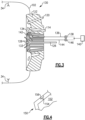
- FIG 4 shows an embodiment 150 wherein the fuel supply 152 leads to a plurality of fuel injection ports 154 extending radially outwardly and into an annular channel 156.
- the plurality of the fuel injection ports 154 deliver fuel as discrete supplies but into a circumferentially continuous annular channel 156.
- the fuel will move radially outwardly and into the path of the inner swirler airflow effectively as a sheet instead of a plurality of discrete jets.
- a combustor 100/130 under this disclosure could be said to include a liner 102 defining a combustion chamber 105.
- An air and fuel mixing body 104/132 is received within the liner and upstream of the combustion chamber.
- the mixing body has a center axis X, and within a bluff-body 111/133.
- a plurality of fuel injection ports 112/134/142 are drilled in the bluff-body such that fuel passes from the fuel supply passage and into a mixing chamber with a component in an axially downstream direction and a radially outward direction relative to the central axis.
- a plurality of inner air swirlers 114 provide air into a mixing chamber with a component in an axially downstream direction, a radially outward direction, and with a circumferential component due to swirler structure.
- the fuel injection ports are downstream of an outlet 115 of the inner air swirlers 114.
- a fuel supply is connected to the central fuel supply and the fuel supply being hydrogen.
- a generally frusto-conical portion 110 of the bluff-body axially upstream of a forward face receives the fuel injection ports.
- a plurality of outer air swirlers 120 delivers air into the combustion chamber 105, and downstream of the mixing chamber.
- air is delivered downstream of the plurality of outer air swirlers with a component in an axially downstream direction, a radially inward direction and with a circumferential component due to swirler structure.
- the controller is operable to selectively deliver fuel from each of said at least two fuel supply passages to associated ones of said fuel injection ports 134/142 dependent on operational conditions.
- the plurality of fuel injection ports lead into a common circumferentially continuous channel 156.
- a plurality of outer air swirlers 120 delivers air into the combustion chamber 105, and downstream of the mixing chamber.
- air is delivered downstream of the plurality of outer air swirlers with a component in an axially downstream direction, a radially inward direction and with a circumferential component due to swirler structure.
- a cooling air supply 126 is connected to the bluff-body, and for delivering cooling air to a forward face of the bluff-body.
Landscapes
- Engineering & Computer Science (AREA)
- Chemical & Material Sciences (AREA)
- Combustion & Propulsion (AREA)
- Mechanical Engineering (AREA)
- General Engineering & Computer Science (AREA)
- Spray-Type Burners (AREA)
Abstract
Description
- The present disclosure relates to a combustor wherein a central bluff-body receives fuel injection ports to deliver fuel downstream of an outlet of an inner air swirler.
- Gas turbine engines are known, and typically include a compressor delivering compressed air into a combustor. Compressed air is mixed with fuel and ignited. Products of the combustion pass downstream over turbine rotors, driving them to rotate. The turbine rotors in turn rotate a compressor rotor and a propulsor rotor such as a fan or propeller.
- Historically, aviation fuel has been utilized with gas turbine engines, especially for aircraft applications. More recently it has been proposed to utilize hydrogen (H2) as a fuel.
- A combustor according to an aspect of the present invention includes a liner defining a combustion chamber. An air and fuel mixing body is received within the liner and upstream of the combustion chamber. The mixing body has a center axis and includes a bluff-body. A plurality of fuel injection ports on the bluff-body communicate with a central fuel supply such that fuel passes from the fuel supply passage and into a mixing chamber with a component in an axially downstream direction and a radially outward direction relative to said central axis. A plurality of inner air swirlers provide air into the mixing chamber with a component in an axially downstream direction, a radially outward direction, and with a circumferential component due to swirler structure. The fuel injection ports are downstream of an outlet of the inner air swirlers.
- In an embodiment, a fuel supply is connected to the central fuel supply, the fuel supply being hydrogen.
- In a further embodiment according to any of the previous embodiments, a generally frusto-conical portion of the bluff-body axially upstream of a forward face receives (or houses) the fuel injection ports.
- In a further embodiment according to any of the previous embodiments, a plurality of outer air swirlers delivers air into the combustion chamber, and downstream of the mixing chamber.
- In a further embodiment according to any of the previous embodiments, air is delivered downstream of the plurality of outer air swirlers with a component in an axially downstream direction, a radially inward direction and with a circumferential component due to swirler structure.
- In a further embodiment according to any of the previous embodiments, there are at least two fuel supply passages with at least one of said at least two fuel supply passages being provided with a valve controlled by a controller, and said controller being operable to selectively deliver fuel from each of said at least two fuel supply passages to associated ones of said fuel injection ports dependent on operational conditions.
- In a further embodiment according to any of the previous embodiments, said plurality of fuel injection ports lead into a common circumferentially continuous channel.
- In a further embodiment according to any of the previous embodiments, a plurality of outer air swirlers delivers air into the combustion chamber, and downstream of the mixing chamber.
- In a further embodiment according to any of the previous embodiments, air is delivered downstream of the plurality of outer air swirlers with a component in an axially downstream direction, a radially inward direction and with a circumferential component due to swirler structure.
- In a further embodiment according to any of the previous embodiments, a cooling air supply is connected to the bluff-body, and for delivering cooling air to a forward face of the bluff-body.
- A gas turbine engine according to another aspect of the present invention includes a compressor section and a turbine section with a combustor intermediate the compressor section and the turbine section. The combustor has a liner defining a combustion chamber, an air and fuel mixing body received within said liner and upstream of the combustion chamber. The mixing body has a center axis, and includes a bluff-body. A plurality of fuel injection ports on the bluff-body communicate with a central fuel supply such that fuel passes from the fuel supply passage and into a mixing chamber with a component in an axially downstream direction and a radially outward direction relative to said central axis. A plurality of inner air swirlers provide air into the mixing chamber with a component in an axially downstream direction, a radially outward direction, and with a circumferential component due to swirler structure. The fuel injection ports are downstream of an outlet of the inner air swirlers.
- In an embodiment, a fuel supply is connected to the central fuel supply, the fuel supply being hydrogen.
- In a further embodiment according to any of the previous embodiments, a generally frusto-conical portion of the bluff-body axially upstream of a forward face receives the fuel injection ports.
- In a further embodiment according to any of the previous embodiments, a plurality of outer swirlers delivers air into the combustion chamber, and downstream of the mixing chamber.
- In a further embodiment according to any of the previous embodiments, air is delivered downstream of said plurality of outer air swirlers with a component in an axially downstream direction, a radially inward direction and with a circumferential component due to swirler structure.
- In a further embodiment according to any of the previous embodiments, there are at least two fuel supply passages with at least one of said at least two fuel supply passages being provided with a valve controlled by a controller, and said controller being operable to selectively deliver fuel from each of said at least two fuel supply passages to associated ones of said fuel injection ports dependent on operational conditions.
- In a further embodiment according to any of the previous embodiments, said plurality of fuel injection ports lead into a common circumferentially continuous channel.
- In a further embodiment according to any of the previous embodiments, a plurality of outer swirlers delivers air into the combustion chamber, and downstream of the mixing chamber.
- In a further embodiment according to any of the previous embodiments, air is delivered downstream of said plurality of outer air swirlers with a component in an axially downstream direction, a radially inward direction and with a circumferential component due to swirler structure.
- In a further embodiment according to any of the previous embodiments, a cooling air supply is connected to the bluff-body, and delivers cooling air to a forward face of the bluff-body.
- These and other features will be best understood from the following drawings and specification, the following is a brief description.
-
-
Figure 1 schematically shows a gas turbine engine. -
Figure 2A shows a first embodiment of a portion of the combustor. -
Figure 2B shows a geometric feature of a mixing body in theFigure 2A embodiment. -
Figure 3 shows a second embodiment fuel and air mixing body. -
Figure 4 shows an optional fuel injection feature. -
Figure 1 schematically illustrates agas turbine engine 20. The examplegas turbine engine 20 is a turbofan that generally incorporates afan section 22, acompressor section 24, acombustor section 26 and aturbine section 28. Thefan section 22 drives air along a bypass flow path B in a bypass duct defined within anacelle 30. Theturbine engine 20 intakes air along a core flow path C into thecompressor section 24 for compression and communication into thecombustor section 26. In thecombustor section 26, the compressed air is mixed with fuel from afuel system 32 and ignited byigniter 34 to generate an exhaust gas flow that expands through theturbine section 28 and is exhausted throughexhaust nozzle 36. Although depicted as a turbofan turbine engine in the disclosed non-limiting embodiment, it should be understood that the concepts described herein are not limited to use with turbofans as the teachings may be applied to other types of turbine engines. As one example, rather than having the propulsor be an enclosed fan, the propulsor may be an open propeller. - A gas turbine engine as disclosed in this application will utilize hydrogen (H2) as a fuel. Challenges are faced by the use of hydrogen, and in particular combustor structure which might be appropriate for aviation fuel may not be as applicable to hydrogen as a fuel.
- One challenge when utilizing hydrogen as a fuel is that it is in a gaseous state and more readily flammable than aviation fuel. This could raise challenges with burn back if ignitions starts too close to the fuel feed. The higher laminar flame speed of hydrogen compared to aviation fuel might also point to an enhanced flame stabilization mechanism.
-
Figure 2A shows acombustor 100 having a liner 102 (shown partially) defining acombustion chamber 105.Ignitors 34 are shown schematically. - An air and
fuel mixing body 104 has afuel feed 106 beginning at aportion 107 and leading to adownstream portion 109 that delivers fuel toward aforward face 108 of a bluff-body 111. The bluff-body 111 enhances flame stabilization. Theportion 109 is centered on axis X. Axis X may also be a center axis of mixingbody 104. - The fuel exits through
fuel ports 112 in frusto-conical portion 110 of bluff-body 111. -
Inner air swirler 114 delivers air with a circumferential component and an axially downstream component, along with a radially outward component all relative to the central axis X. As can be appreciated, the inner air swirler has adownstream end 115 leading into achamber portion 116, and which is upstream of thefuel injection ports 112. - It should be understood that
fuel ports 112 are spaced about a circumference of the central axis X. - When the fuel leaves the
ports 112, the swirling air in thechamber 116 begins to mix with the fuel. As the air and fuel mix and move further downstream, they encounter an outer air swirler air flow fromouter air swirlers 120 which are defined in abody portion 122 of the mixingbody 104 positioned radially outwardly of theinner swirler 114. - The fuel injection ports deliver fuel as discrete supplies but into a circumferentially continuous annular channel, allowing fuel to move radially outwardly and into the path of the inner swirler airflow effectively as a sheet instead of a plurality of discrete jets.
- The
outer air swirlers 120 have a downstream end oroutlets 121 which provides air moving with a circumferential component, an axially downstream component, along with a radially inward component all relative to central axis X. That outer swirling air encounters the mixed inner air and fuel and drives all of it downstream toward apotion 124 of thecombustor chamber 105. - The structure of
swirlers - By moving the mixed fuel and air downstream into the area forward of the
forward face 108 of the bluff-body 111, the risk of burn back reaching thefuel injection ports 112 is reduced. - As shown, a supply of cooling
air 126 may be delivered to theforward face 108 of bluff-body 111, and radially inward of thefuel ports 112. The air is shown with a component in a radially outward direction relative to the axis X, and serves to cool theforward face 108. -
Figure 2B shows geometric feature of theFigure 2A embodiment. As shown, thefuel injection ports 112 extend at an angle A with a radially outer component and an axially downstream component. - Similarly, air leaving the
inner swirler 114 has a radially outwardly component and in an axially downstream direction and defining an angle B with central axis X. - In contrast, the
outer swirler 120 delivers air with a radially inner component in an axially downstream direction and defining an angle C with central axis X. - The combination of these three directions ensure efficient and thorough mixing downstream of the
outlet 121. -
Figure 3 shows anotherembodiment 130. Here, the forward face 131 of the bluff-body 133 is provided with a first set offuel injection ports 134 communicating with a firstfuel supply line 136 and controlled by avalve 138. - A second group of
fuel injection ports 142 communicates with theline 144 having avalve 146. Acontrol 140 is programmed to controlvalves fuel injection ports - One of the
valves 138 may be opened to provide a primary or pilot fuel supply such as when ignition is initially beginning. Theother valve 146 may control the flow of fuel toline 144 andfuel supply ports 142 as a secondary source of fuel. The secondary source of fuel may be opened at higher fuel flow conditions such as takeoff or cruise. - The
control 140 may be a standalone electronic controller, or it could be incorporated into a full authority digital electronic controller (FADEC) for the entire associated gas turbine engine. - The time when fuel should be supplied between the two supplies may be as known in the art. However, the use of the unique arrangement in the air
fuel mixing body 132 in this embodiment provides more efficient mixing of the fuel and air under either condition. - Again, a supply of cooling
air 126 delivers air toports 128 at the forward face 131. -
Figure 4 shows anembodiment 150 wherein thefuel supply 152 leads to a plurality offuel injection ports 154 extending radially outwardly and into anannular channel 156. Now, the plurality of thefuel injection ports 154 deliver fuel as discrete supplies but into a circumferentially continuousannular channel 156. Thus, the fuel will move radially outwardly and into the path of the inner swirler airflow effectively as a sheet instead of a plurality of discrete jets. - In a featured embodiment, a
combustor 100/130 under this disclosure could be said to include aliner 102 defining acombustion chamber 105. An air andfuel mixing body 104/132 is received within the liner and upstream of the combustion chamber. The mixing body has a center axis X, and within a bluff-body 111/133. A plurality offuel injection ports 112/134/142 are drilled in the bluff-body such that fuel passes from the fuel supply passage and into a mixing chamber with a component in an axially downstream direction and a radially outward direction relative to the central axis. A plurality ofinner air swirlers 114 provide air into a mixing chamber with a component in an axially downstream direction, a radially outward direction, and with a circumferential component due to swirler structure. The fuel injection ports are downstream of anoutlet 115 of theinner air swirlers 114. - In another embodiment according to the previous embodiment, a fuel supply is connected to the central fuel supply and the fuel supply being hydrogen.
- In another embodiment according to any of the previous embodiments, a generally frusto-
conical portion 110 of the bluff-body axially upstream of a forward face receives the fuel injection ports. - In another embodiment according to any of the previous embodiments, a plurality of
outer air swirlers 120 delivers air into thecombustion chamber 105, and downstream of the mixing chamber. - In another embodiment according to any of the previous embodiments, air is delivered downstream of the plurality of outer air swirlers with a component in an axially downstream direction, a radially inward direction and with a circumferential component due to swirler structure.
- In another embodiment according to any of the previous embodiments, there are at least two
fuel supply passages 136/144 with at least one of said at least two fuel supply passages being provided with avalve 138/146 controlled by acontroller 140. The controller is operable to selectively deliver fuel from each of said at least two fuel supply passages to associated ones of saidfuel injection ports 134/142 dependent on operational conditions. - In another embodiment according to any of the previous embodiments, the plurality of fuel injection ports lead into a common circumferentially
continuous channel 156. - In another embodiment according to any of the previous embodiments, a plurality of
outer air swirlers 120 delivers air into thecombustion chamber 105, and downstream of the mixing chamber. - In another embodiment according to any of the previous embodiments, air is delivered downstream of the plurality of outer air swirlers with a component in an axially downstream direction, a radially inward direction and with a circumferential component due to swirler structure.
- In another embodiment according to any of the previous embodiments, a cooling
air supply 126 is connected to the bluff-body, and for delivering cooling air to a forward face of the bluff-body. - A gas turbine engine incorporating any of the above features is also disclosed and claimed.
- Although embodiments have been disclosed, a worker of skill in this art would recognize that modifications would come within the scope of this disclosure. For that reason, the following claims should be studied to determine the true scope and content of this disclosure.
Claims (10)
- A combustor (100; 130) comprising:a liner (102) defining a combustion chamber (105);an air and fuel mixing body (104; 132) received within said liner (102) and upstream of the combustion chamber (105);the mixing body (104; 132) has a center axis (X) and includes a bluff-body (111; 133);a plurality of fuel injection ports (112; 134, 142; 154) on the bluff-body (111; 133) and communicating with a central fuel supply such that fuel passes from a fuel supply passage (106; 136, 144) and into a mixing chamber (116) with a component in an axially downstream direction and a radially outward direction relative to said center axis (X);a plurality of inner air swirlers (114) configured to provide air into the mixing chamber (116) with a component in an axially downstream direction, a component in a radially outward direction, and with a circumferential component due to swirler structure; andthe fuel injection ports (112... 154) being downstream of an outlet (115) of the inner air swirlers (114).
- The combustor (100; 130) as set forth in claim 1, wherein a generally frusto-conical portion (110) of the bluff-body (111) axially upstream of a forward face (108) of the bluff-body (111) receives the fuel injection ports (112).
- The combustor (100; 130) as set forth in claim 1 or 2, wherein a plurality of outer air swirlers (120) is configured to deliver air into the combustion chamber (105), and downstream of the mixing chamber (116).
- The combustor (100; 130) as set forth in claim 3, wherein air is delivered downstream of the plurality of outer air swirlers (120) with a component in an axially downstream direction, a component in a radially inward direction and with a circumferential component due to swirler structure.
- The combustor (100; 130) as set forth in any preceding claim, wherein there are at least two fuel supply passages (136, 144) with at least one of said at least two fuel supply passages (136, 144) being provided with a valve (138, 146) controlled by a controller (140), and said controller (140) being operable to selectively deliver fuel from each of said at least two fuel supply passages (136, 144) to associated ones of said fuel injection ports (134, 142) dependent on operational conditions.
- The combustor (100; 130) as set forth in any preceding claim, wherein said plurality of fuel injection ports (154) lead into a common circumferentially continuous channel (156).
- The combustor (100; 130) as set forth in any preceding claim, wherein a cooling air supply (126) is connected to the bluff-body (111; 133), and for delivering cooling air (126) to a/the forward face (108; 131) of the bluff-body (111; 133).
- The combustor (100; 130) as set forth in any preceding claim, wherein a fuel supply is connected to the central fuel supply and the fuel supply is hydrogen.
- A gas turbine engine (20) comprising:
a compressor section (24) and a turbine section (28) with a combustor (100; 130) as set forth in any of claims 1 to 7 intermediate the compressor section (24) and the turbine section (28). - The gas turbine engine (20) as set forth in claim 9, wherein a fuel supply is connected to the central fuel supply and the fuel supply is hydrogen.
Applications Claiming Priority (1)
| Application Number | Priority Date | Filing Date | Title |
|---|---|---|---|
| US18/104,978 US11873993B1 (en) | 2023-02-02 | 2023-02-02 | Combustor for gas turbine engine with central fuel injection ports |
Publications (2)
| Publication Number | Publication Date |
|---|---|
| EP4411229A1 true EP4411229A1 (en) | 2024-08-07 |
| EP4411229B1 EP4411229B1 (en) | 2026-04-01 |
Family
ID=89511263
Family Applications (1)
| Application Number | Title | Priority Date | Filing Date |
|---|---|---|---|
| EP24155606.7A Active EP4411229B1 (en) | 2023-02-02 | 2024-02-02 | Combustor for gas turbine engine with central fuel injection ports |
Country Status (3)
| Country | Link |
|---|---|
| US (1) | US11873993B1 (en) |
| EP (1) | EP4411229B1 (en) |
| CA (1) | CA3223486A1 (en) |
Families Citing this family (1)
| Publication number | Priority date | Publication date | Assignee | Title |
|---|---|---|---|---|
| US20250035306A1 (en) * | 2023-07-25 | 2025-01-30 | Collins Engine Nozzles, Inc. | Flat spray fuel injectors |
Citations (4)
| Publication number | Priority date | Publication date | Assignee | Title |
|---|---|---|---|---|
| US3254846A (en) * | 1965-01-21 | 1966-06-07 | Hauck Mfg Co | Oil atomizing burner using low pressure air |
| WO2017175958A1 (en) * | 2016-04-08 | 2017-10-12 | 한화테크윈주식회사 | Industrial combustor |
| GB2593123A (en) * | 2019-06-25 | 2021-09-22 | Siemens Ag | Combustor for a gas turbine |
| WO2022214384A1 (en) * | 2021-04-06 | 2022-10-13 | Siemens Energy Global GmbH & Co. KG | Combustor for a gas turbine |
Family Cites Families (35)
| Publication number | Priority date | Publication date | Assignee | Title |
|---|---|---|---|---|
| US4854127A (en) | 1988-01-14 | 1989-08-08 | General Electric Company | Bimodal swirler injector for a gas turbine combustor |
| US5218824A (en) | 1992-06-25 | 1993-06-15 | Solar Turbines Incorporated | Low emission combustion nozzle for use with a gas turbine engine |
| US6547163B1 (en) | 1999-10-01 | 2003-04-15 | Parker-Hannifin Corporation | Hybrid atomizing fuel nozzle |
| US7065972B2 (en) | 2004-05-21 | 2006-06-27 | Honeywell International, Inc. | Fuel-air mixing apparatus for reducing gas turbine combustor exhaust emissions |
| US8266911B2 (en) | 2005-11-14 | 2012-09-18 | General Electric Company | Premixing device for low emission combustion process |
| WO2008097320A2 (en) | 2006-06-01 | 2008-08-14 | Virginia Tech Intellectual Properties, Inc. | Premixing injector for gas turbine engines |
| US20080104961A1 (en) | 2006-11-08 | 2008-05-08 | Ronald Scott Bunker | Method and apparatus for enhanced mixing in premixing devices |
| US7832212B2 (en) | 2006-11-10 | 2010-11-16 | General Electric Company | High expansion fuel injection slot jet and method for enhancing mixing in premixing devices |
| US8099960B2 (en) | 2006-11-17 | 2012-01-24 | General Electric Company | Triple counter rotating swirler and method of use |
| US8413445B2 (en) | 2007-05-11 | 2013-04-09 | General Electric Company | Method and system for porous flame holder for hydrogen and syngas combustion |
| US8661779B2 (en) | 2008-09-26 | 2014-03-04 | Siemens Energy, Inc. | Flex-fuel injector for gas turbines |
| US8539773B2 (en) | 2009-02-04 | 2013-09-24 | General Electric Company | Premixed direct injection nozzle for highly reactive fuels |
| EP2299178B1 (en) | 2009-09-17 | 2015-11-04 | Alstom Technology Ltd | A method and gas turbine combustion system for safely mixing H2-rich fuels with air |
| US8794545B2 (en) | 2009-09-25 | 2014-08-05 | General Electric Company | Internal baffling for fuel injector |
| JP5084847B2 (en) | 2010-01-13 | 2012-11-28 | 株式会社日立製作所 | Gas turbine combustor |
| US8893500B2 (en) | 2011-05-18 | 2014-11-25 | Solar Turbines Inc. | Lean direct fuel injector |
| JP5630424B2 (en) | 2011-11-21 | 2014-11-26 | 三菱日立パワーシステムズ株式会社 | Gas turbine combustor |
| JP5926635B2 (en) | 2012-07-04 | 2016-05-25 | 三菱日立パワーシステムズ株式会社 | Gas turbine combustor |
| CA2830031C (en) | 2012-10-23 | 2016-03-15 | Alstom Technology Ltd. | Burner for a can combustor |
| CN104075344B (en) | 2013-03-25 | 2016-07-06 | 通用电气公司 | Start and operate fuel nozzle system and the method for gas turbine with low calorie fuels |
| JP6602004B2 (en) | 2014-09-29 | 2019-11-06 | 川崎重工業株式会社 | Fuel injector and gas turbine |
| JP2016109309A (en) | 2014-12-02 | 2016-06-20 | 川崎重工業株式会社 | Combustor for gas turbine, and gas turbine |
| JP2016148507A (en) | 2014-12-30 | 2016-08-18 | ゼネラル・エレクトリック・カンパニイ | Pilot nozzle in gas turbine combustor |
| WO2016122529A1 (en) | 2015-01-29 | 2016-08-04 | Siemens Energy, Inc. | Fuel injector including tandem vanes for injecting alternate fuels in a gas turbine |
| WO2016122521A1 (en) | 2015-01-29 | 2016-08-04 | Siemens Energy, Inc. | Fuel injector including a lobed mixer and vanes for injecting alternate fuels in a gas turbine |
| EP3098514A1 (en) | 2015-05-29 | 2016-11-30 | Siemens Aktiengesellschaft | Combustor arrangement |
| CN107735618B (en) | 2015-07-06 | 2020-06-26 | 西门子股份公司 | Combustor for a gas turbine and method of operating a combustor |
| GB201511841D0 (en) * | 2015-07-07 | 2015-08-19 | Rolls Royce Plc | Fuel spray nozel for a gas turbine engine |
| US20170227224A1 (en) | 2016-02-09 | 2017-08-10 | Solar Turbines Incorporated | Fuel injector for combustion engine system, and engine operating method |
| US9976522B2 (en) | 2016-04-15 | 2018-05-22 | Solar Turbines Incorporated | Fuel injector for combustion engine and staged fuel delivery method |
| US10502425B2 (en) | 2016-06-03 | 2019-12-10 | General Electric Company | Contoured shroud swirling pre-mix fuel injector assembly |
| US10295190B2 (en) | 2016-11-04 | 2019-05-21 | General Electric Company | Centerbody injector mini mixer fuel nozzle assembly |
| US11378275B2 (en) | 2019-12-06 | 2022-07-05 | Raytheon Technologies Corporation | High shear swirler with recessed fuel filmer for a gas turbine engine |
| US11506390B2 (en) | 2019-12-06 | 2022-11-22 | Raytheon Technologies Corporation | Multi-fuel bluff-body piloted high-shear injector and method of using same |
| US11713881B2 (en) * | 2020-01-08 | 2023-08-01 | General Electric Company | Premixer for a combustor |
-
2023
- 2023-02-02 US US18/104,978 patent/US11873993B1/en active Active
- 2023-12-18 CA CA3223486A patent/CA3223486A1/en active Pending
-
2024
- 2024-02-02 EP EP24155606.7A patent/EP4411229B1/en active Active
Patent Citations (4)
| Publication number | Priority date | Publication date | Assignee | Title |
|---|---|---|---|---|
| US3254846A (en) * | 1965-01-21 | 1966-06-07 | Hauck Mfg Co | Oil atomizing burner using low pressure air |
| WO2017175958A1 (en) * | 2016-04-08 | 2017-10-12 | 한화테크윈주식회사 | Industrial combustor |
| GB2593123A (en) * | 2019-06-25 | 2021-09-22 | Siemens Ag | Combustor for a gas turbine |
| WO2022214384A1 (en) * | 2021-04-06 | 2022-10-13 | Siemens Energy Global GmbH & Co. KG | Combustor for a gas turbine |
Also Published As
| Publication number | Publication date |
|---|---|
| US11873993B1 (en) | 2024-01-16 |
| CA3223486A1 (en) | 2025-04-17 |
| EP4411229B1 (en) | 2026-04-01 |
Similar Documents
| Publication | Publication Date | Title |
|---|---|---|
| EP3537048B1 (en) | A lean burn fuel injector | |
| CN110966619A (en) | Fuel nozzle | |
| EP2503131A2 (en) | Hybrid slinger combustion system | |
| US11578871B1 (en) | Gas turbine engine combustor with primary and secondary fuel injectors | |
| US20230015929A1 (en) | Lean burn injector with supply line switching | |
| EP4411229B1 (en) | Combustor for gas turbine engine with central fuel injection ports | |
| EP4617568A1 (en) | Cluster of swirled mini-mixers for fuel-staged, axially staged combustion | |
| US20260055894A1 (en) | Combustor with distributed air and fuel mixing | |
| EP4411232A1 (en) | High shear fuel distributor | |
| EP4411234A1 (en) | Hydrogen-driven gas turbine engine with injector ring | |
| US20210301736A1 (en) | Method of operating a combustor head end assembly | |
| EP4411242B1 (en) | Combustor with central fuel injection and downstream air mixing | |
| EP4411245B1 (en) | Combustor with fuel and air mixing plenum | |
| EP4411225B1 (en) | Combustor with air/fuel mixer creating mixed cloud | |
| EP4411238B1 (en) | Combustor with helix air and fuel mixing passage | |
| EP4411235B1 (en) | Hydrogen-driven gas turbine engine with injector ring and fuel staging | |
| US20250092848A1 (en) | Supplemental thrust system with rotating detonation combustor | |
| US11867400B1 (en) | Combustor with fuel plenum with mixing passages having baffles | |
| EP4411240A1 (en) | Combined air swirler and fuel distributor |
Legal Events
| Date | Code | Title | Description |
|---|---|---|---|
| PUAI | Public reference made under article 153(3) epc to a published international application that has entered the european phase |
Free format text: ORIGINAL CODE: 0009012 |
|
| STAA | Information on the status of an ep patent application or granted ep patent |
Free format text: STATUS: THE APPLICATION HAS BEEN PUBLISHED |
|
| AK | Designated contracting states |
Kind code of ref document: A1 Designated state(s): AL AT BE BG CH CY CZ DE DK EE ES FI FR GB GR HR HU IE IS IT LI LT LU LV MC ME MK MT NL NO PL PT RO RS SE SI SK SM TR |
|
| STAA | Information on the status of an ep patent application or granted ep patent |
Free format text: STATUS: REQUEST FOR EXAMINATION WAS MADE |
|
| 17P | Request for examination filed |
Effective date: 20250207 |
|
| GRAP | Despatch of communication of intention to grant a patent |
Free format text: ORIGINAL CODE: EPIDOSNIGR1 |
|
| STAA | Information on the status of an ep patent application or granted ep patent |
Free format text: STATUS: GRANT OF PATENT IS INTENDED |
|
| INTG | Intention to grant announced |
Effective date: 20250923 |
|
| GRAS | Grant fee paid |
Free format text: ORIGINAL CODE: EPIDOSNIGR3 |
|
| GRAA | (expected) grant |
Free format text: ORIGINAL CODE: 0009210 |
|
| STAA | Information on the status of an ep patent application or granted ep patent |
Free format text: STATUS: THE PATENT HAS BEEN GRANTED |
|
| AK | Designated contracting states |
Kind code of ref document: B1 Designated state(s): AL AT BE BG CH CY CZ DE DK EE ES FI FR GB GR HR HU IE IS IT LI LT LU LV MC ME MK MT NL NO PL PT RO RS SE SI SK SM TR |
|
| REG | Reference to a national code |
Ref country code: CH Ref legal event code: F10 Free format text: ST27 STATUS EVENT CODE: U-0-0-F10-F00 (AS PROVIDED BY THE NATIONAL OFFICE) Effective date: 20260401 Ref country code: GB Ref legal event code: FG4D |
|
| REG | Reference to a national code |
Ref country code: DE Ref legal event code: R096 Ref document number: 602024003498 Country of ref document: DE |
|
| REG | Reference to a national code |
Ref country code: IE Ref legal event code: FG4D |