EP4411160A1 - Dichtungsanordnung und deren verwendung - Google Patents
Dichtungsanordnung und deren verwendung Download PDFInfo
- Publication number
- EP4411160A1 EP4411160A1 EP24150623.7A EP24150623A EP4411160A1 EP 4411160 A1 EP4411160 A1 EP 4411160A1 EP 24150623 A EP24150623 A EP 24150623A EP 4411160 A1 EP4411160 A1 EP 4411160A1
- Authority
- EP
- European Patent Office
- Prior art keywords
- sealing
- ring
- radial
- axial
- sealing arrangement
- Prior art date
- Legal status (The legal status is an assumption and is not a legal conclusion. Google has not performed a legal analysis and makes no representation as to the accuracy of the status listed.)
- Withdrawn
Links
Images
Classifications
-
- F—MECHANICAL ENGINEERING; LIGHTING; HEATING; WEAPONS; BLASTING
- F16—ENGINEERING ELEMENTS AND UNITS; GENERAL MEASURES FOR PRODUCING AND MAINTAINING EFFECTIVE FUNCTIONING OF MACHINES OR INSTALLATIONS; THERMAL INSULATION IN GENERAL
- F16C—SHAFTS; FLEXIBLE SHAFTS; ELEMENTS OR CRANKSHAFT MECHANISMS; ROTARY BODIES OTHER THAN GEARING ELEMENTS; BEARINGS
- F16C33/00—Parts of bearings; Special methods for making bearings or parts thereof
- F16C33/72—Sealings
- F16C33/76—Sealings of ball or roller bearings
- F16C33/78—Sealings of ball or roller bearings with a diaphragm, disc, or ring, with or without resilient members
- F16C33/7816—Details of the sealing or parts thereof, e.g. geometry, material
- F16C33/782—Details of the sealing or parts thereof, e.g. geometry, material of the sealing region
- F16C33/7823—Details of the sealing or parts thereof, e.g. geometry, material of the sealing region of sealing lips
-
- F—MECHANICAL ENGINEERING; LIGHTING; HEATING; WEAPONS; BLASTING
- F16—ENGINEERING ELEMENTS AND UNITS; GENERAL MEASURES FOR PRODUCING AND MAINTAINING EFFECTIVE FUNCTIONING OF MACHINES OR INSTALLATIONS; THERMAL INSULATION IN GENERAL
- F16C—SHAFTS; FLEXIBLE SHAFTS; ELEMENTS OR CRANKSHAFT MECHANISMS; ROTARY BODIES OTHER THAN GEARING ELEMENTS; BEARINGS
- F16C33/00—Parts of bearings; Special methods for making bearings or parts thereof
- F16C33/72—Sealings
- F16C33/76—Sealings of ball or roller bearings
- F16C33/78—Sealings of ball or roller bearings with a diaphragm, disc, or ring, with or without resilient members
- F16C33/7816—Details of the sealing or parts thereof, e.g. geometry, material
- F16C33/783—Details of the sealing or parts thereof, e.g. geometry, material of the mounting region
-
- F—MECHANICAL ENGINEERING; LIGHTING; HEATING; WEAPONS; BLASTING
- F16—ENGINEERING ELEMENTS AND UNITS; GENERAL MEASURES FOR PRODUCING AND MAINTAINING EFFECTIVE FUNCTIONING OF MACHINES OR INSTALLATIONS; THERMAL INSULATION IN GENERAL
- F16C—SHAFTS; FLEXIBLE SHAFTS; ELEMENTS OR CRANKSHAFT MECHANISMS; ROTARY BODIES OTHER THAN GEARING ELEMENTS; BEARINGS
- F16C33/00—Parts of bearings; Special methods for making bearings or parts thereof
- F16C33/72—Sealings
- F16C33/76—Sealings of ball or roller bearings
- F16C33/78—Sealings of ball or roller bearings with a diaphragm, disc, or ring, with or without resilient members
- F16C33/7869—Sealings of ball or roller bearings with a diaphragm, disc, or ring, with or without resilient members mounted with a cylindrical portion to the inner surface of the outer race and having a radial portion extending inward
- F16C33/7873—Sealings of ball or roller bearings with a diaphragm, disc, or ring, with or without resilient members mounted with a cylindrical portion to the inner surface of the outer race and having a radial portion extending inward with a single sealing ring of generally L-shaped cross-section
- F16C33/7876—Sealings of ball or roller bearings with a diaphragm, disc, or ring, with or without resilient members mounted with a cylindrical portion to the inner surface of the outer race and having a radial portion extending inward with a single sealing ring of generally L-shaped cross-section with sealing lips
-
- F—MECHANICAL ENGINEERING; LIGHTING; HEATING; WEAPONS; BLASTING
- F16—ENGINEERING ELEMENTS AND UNITS; GENERAL MEASURES FOR PRODUCING AND MAINTAINING EFFECTIVE FUNCTIONING OF MACHINES OR INSTALLATIONS; THERMAL INSULATION IN GENERAL
- F16C—SHAFTS; FLEXIBLE SHAFTS; ELEMENTS OR CRANKSHAFT MECHANISMS; ROTARY BODIES OTHER THAN GEARING ELEMENTS; BEARINGS
- F16C19/00—Bearings with rolling contact, for exclusively rotary movement
- F16C19/02—Bearings with rolling contact, for exclusively rotary movement with bearing balls essentially of the same size in one or more circular rows
- F16C19/04—Bearings with rolling contact, for exclusively rotary movement with bearing balls essentially of the same size in one or more circular rows for radial load mainly
- F16C19/06—Bearings with rolling contact, for exclusively rotary movement with bearing balls essentially of the same size in one or more circular rows for radial load mainly with a single row or balls
-
- F—MECHANICAL ENGINEERING; LIGHTING; HEATING; WEAPONS; BLASTING
- F16—ENGINEERING ELEMENTS AND UNITS; GENERAL MEASURES FOR PRODUCING AND MAINTAINING EFFECTIVE FUNCTIONING OF MACHINES OR INSTALLATIONS; THERMAL INSULATION IN GENERAL
- F16C—SHAFTS; FLEXIBLE SHAFTS; ELEMENTS OR CRANKSHAFT MECHANISMS; ROTARY BODIES OTHER THAN GEARING ELEMENTS; BEARINGS
- F16C19/00—Bearings with rolling contact, for exclusively rotary movement
- F16C19/02—Bearings with rolling contact, for exclusively rotary movement with bearing balls essentially of the same size in one or more circular rows
- F16C19/14—Bearings with rolling contact, for exclusively rotary movement with bearing balls essentially of the same size in one or more circular rows for both radial and axial load
- F16C19/16—Bearings with rolling contact, for exclusively rotary movement with bearing balls essentially of the same size in one or more circular rows for both radial and axial load with a single row of balls
- F16C19/163—Bearings with rolling contact, for exclusively rotary movement with bearing balls essentially of the same size in one or more circular rows for both radial and axial load with a single row of balls with angular contact
-
- F—MECHANICAL ENGINEERING; LIGHTING; HEATING; WEAPONS; BLASTING
- F16—ENGINEERING ELEMENTS AND UNITS; GENERAL MEASURES FOR PRODUCING AND MAINTAINING EFFECTIVE FUNCTIONING OF MACHINES OR INSTALLATIONS; THERMAL INSULATION IN GENERAL
- F16C—SHAFTS; FLEXIBLE SHAFTS; ELEMENTS OR CRANKSHAFT MECHANISMS; ROTARY BODIES OTHER THAN GEARING ELEMENTS; BEARINGS
- F16C19/00—Bearings with rolling contact, for exclusively rotary movement
- F16C19/02—Bearings with rolling contact, for exclusively rotary movement with bearing balls essentially of the same size in one or more circular rows
- F16C19/14—Bearings with rolling contact, for exclusively rotary movement with bearing balls essentially of the same size in one or more circular rows for both radial and axial load
- F16C19/18—Bearings with rolling contact, for exclusively rotary movement with bearing balls essentially of the same size in one or more circular rows for both radial and axial load with two or more rows of balls
- F16C19/181—Bearings with rolling contact, for exclusively rotary movement with bearing balls essentially of the same size in one or more circular rows for both radial and axial load with two or more rows of balls with angular contact
-
- F—MECHANICAL ENGINEERING; LIGHTING; HEATING; WEAPONS; BLASTING
- F16—ENGINEERING ELEMENTS AND UNITS; GENERAL MEASURES FOR PRODUCING AND MAINTAINING EFFECTIVE FUNCTIONING OF MACHINES OR INSTALLATIONS; THERMAL INSULATION IN GENERAL
- F16C—SHAFTS; FLEXIBLE SHAFTS; ELEMENTS OR CRANKSHAFT MECHANISMS; ROTARY BODIES OTHER THAN GEARING ELEMENTS; BEARINGS
- F16C2240/00—Specified values or numerical ranges of parameters; Relations between them
- F16C2240/40—Linear dimensions, e.g. length, radius, thickness, gap
- F16C2240/46—Gap sizes or clearances
-
- F—MECHANICAL ENGINEERING; LIGHTING; HEATING; WEAPONS; BLASTING
- F16—ENGINEERING ELEMENTS AND UNITS; GENERAL MEASURES FOR PRODUCING AND MAINTAINING EFFECTIVE FUNCTIONING OF MACHINES OR INSTALLATIONS; THERMAL INSULATION IN GENERAL
- F16C—SHAFTS; FLEXIBLE SHAFTS; ELEMENTS OR CRANKSHAFT MECHANISMS; ROTARY BODIES OTHER THAN GEARING ELEMENTS; BEARINGS
- F16C2240/00—Specified values or numerical ranges of parameters; Relations between them
- F16C2240/40—Linear dimensions, e.g. length, radius, thickness, gap
- F16C2240/60—Thickness, e.g. thickness of coatings
-
- F—MECHANICAL ENGINEERING; LIGHTING; HEATING; WEAPONS; BLASTING
- F16—ENGINEERING ELEMENTS AND UNITS; GENERAL MEASURES FOR PRODUCING AND MAINTAINING EFFECTIVE FUNCTIONING OF MACHINES OR INSTALLATIONS; THERMAL INSULATION IN GENERAL
- F16C—SHAFTS; FLEXIBLE SHAFTS; ELEMENTS OR CRANKSHAFT MECHANISMS; ROTARY BODIES OTHER THAN GEARING ELEMENTS; BEARINGS
- F16C2240/00—Specified values or numerical ranges of parameters; Relations between them
- F16C2240/40—Linear dimensions, e.g. length, radius, thickness, gap
- F16C2240/70—Diameters; Radii
-
- F—MECHANICAL ENGINEERING; LIGHTING; HEATING; WEAPONS; BLASTING
- F16—ENGINEERING ELEMENTS AND UNITS; GENERAL MEASURES FOR PRODUCING AND MAINTAINING EFFECTIVE FUNCTIONING OF MACHINES OR INSTALLATIONS; THERMAL INSULATION IN GENERAL
- F16C—SHAFTS; FLEXIBLE SHAFTS; ELEMENTS OR CRANKSHAFT MECHANISMS; ROTARY BODIES OTHER THAN GEARING ELEMENTS; BEARINGS
- F16C2240/00—Specified values or numerical ranges of parameters; Relations between them
- F16C2240/90—Surface areas
-
- F—MECHANICAL ENGINEERING; LIGHTING; HEATING; WEAPONS; BLASTING
- F16—ENGINEERING ELEMENTS AND UNITS; GENERAL MEASURES FOR PRODUCING AND MAINTAINING EFFECTIVE FUNCTIONING OF MACHINES OR INSTALLATIONS; THERMAL INSULATION IN GENERAL
- F16C—SHAFTS; FLEXIBLE SHAFTS; ELEMENTS OR CRANKSHAFT MECHANISMS; ROTARY BODIES OTHER THAN GEARING ELEMENTS; BEARINGS
- F16C2380/00—Electrical apparatus
- F16C2380/26—Dynamo-electric machines or combinations therewith, e.g. electro-motors and generators
-
- F—MECHANICAL ENGINEERING; LIGHTING; HEATING; WEAPONS; BLASTING
- F16—ENGINEERING ELEMENTS AND UNITS; GENERAL MEASURES FOR PRODUCING AND MAINTAINING EFFECTIVE FUNCTIONING OF MACHINES OR INSTALLATIONS; THERMAL INSULATION IN GENERAL
- F16C—SHAFTS; FLEXIBLE SHAFTS; ELEMENTS OR CRANKSHAFT MECHANISMS; ROTARY BODIES OTHER THAN GEARING ELEMENTS; BEARINGS
- F16C33/00—Parts of bearings; Special methods for making bearings or parts thereof
- F16C33/72—Sealings
- F16C33/76—Sealings of ball or roller bearings
- F16C33/78—Sealings of ball or roller bearings with a diaphragm, disc, or ring, with or without resilient members
- F16C33/784—Sealings of ball or roller bearings with a diaphragm, disc, or ring, with or without resilient members mounted to a groove in the inner surface of the outer race and extending toward the inner race
- F16C33/7843—Sealings of ball or roller bearings with a diaphragm, disc, or ring, with or without resilient members mounted to a groove in the inner surface of the outer race and extending toward the inner race with a single annular sealing disc
- F16C33/7853—Sealings of ball or roller bearings with a diaphragm, disc, or ring, with or without resilient members mounted to a groove in the inner surface of the outer race and extending toward the inner race with a single annular sealing disc with one or more sealing lips to contact the inner race
- F16C33/7856—Sealings of ball or roller bearings with a diaphragm, disc, or ring, with or without resilient members mounted to a groove in the inner surface of the outer race and extending toward the inner race with a single annular sealing disc with one or more sealing lips to contact the inner race with a single sealing lip
-
- F—MECHANICAL ENGINEERING; LIGHTING; HEATING; WEAPONS; BLASTING
- F16—ENGINEERING ELEMENTS AND UNITS; GENERAL MEASURES FOR PRODUCING AND MAINTAINING EFFECTIVE FUNCTIONING OF MACHINES OR INSTALLATIONS; THERMAL INSULATION IN GENERAL
- F16C—SHAFTS; FLEXIBLE SHAFTS; ELEMENTS OR CRANKSHAFT MECHANISMS; ROTARY BODIES OTHER THAN GEARING ELEMENTS; BEARINGS
- F16C33/00—Parts of bearings; Special methods for making bearings or parts thereof
- F16C33/72—Sealings
- F16C33/76—Sealings of ball or roller bearings
- F16C33/78—Sealings of ball or roller bearings with a diaphragm, disc, or ring, with or without resilient members
- F16C33/784—Sealings of ball or roller bearings with a diaphragm, disc, or ring, with or without resilient members mounted to a groove in the inner surface of the outer race and extending toward the inner race
- F16C33/7859—Sealings of ball or roller bearings with a diaphragm, disc, or ring, with or without resilient members mounted to a groove in the inner surface of the outer race and extending toward the inner race with a further sealing element
- F16C33/7863—Sealings of ball or roller bearings with a diaphragm, disc, or ring, with or without resilient members mounted to a groove in the inner surface of the outer race and extending toward the inner race with a further sealing element mounted to the inner race, e.g. a flinger to use centrifugal effect
-
- F—MECHANICAL ENGINEERING; LIGHTING; HEATING; WEAPONS; BLASTING
- F16—ENGINEERING ELEMENTS AND UNITS; GENERAL MEASURES FOR PRODUCING AND MAINTAINING EFFECTIVE FUNCTIONING OF MACHINES OR INSTALLATIONS; THERMAL INSULATION IN GENERAL
- F16C—SHAFTS; FLEXIBLE SHAFTS; ELEMENTS OR CRANKSHAFT MECHANISMS; ROTARY BODIES OTHER THAN GEARING ELEMENTS; BEARINGS
- F16C33/00—Parts of bearings; Special methods for making bearings or parts thereof
- F16C33/72—Sealings
- F16C33/76—Sealings of ball or roller bearings
- F16C33/78—Sealings of ball or roller bearings with a diaphragm, disc, or ring, with or without resilient members
- F16C33/784—Sealings of ball or roller bearings with a diaphragm, disc, or ring, with or without resilient members mounted to a groove in the inner surface of the outer race and extending toward the inner race
- F16C33/7859—Sealings of ball or roller bearings with a diaphragm, disc, or ring, with or without resilient members mounted to a groove in the inner surface of the outer race and extending toward the inner race with a further sealing element
- F16C33/7866—Sealings of ball or roller bearings with a diaphragm, disc, or ring, with or without resilient members mounted to a groove in the inner surface of the outer race and extending toward the inner race with a further sealing element with sealing lips
Definitions
- the invention relates to a sealing arrangement and its use.
- Sealing arrangements are known in a wide variety of designs and are used in many areas, for example for sealing electric motors.
- the invention is based on the object of further developing a sealing arrangement for sealing rolling bearings in such a way that it is easy to assemble and easy and inexpensive to manufacture and has good performance properties over a long service life.
- dynamically stressed and statically stressed sealing points in the sealing arrangement are to be protected against the ingress of contamination and moisture.
- a sealing arrangement comprising a rolling bearing with an inner ring, an outer ring and rolling elements which are arranged between the inner ring and the outer ring, and a seal comprising a sealing ring made of a sealing material, with a dynamically stressed sealing lip and a statically stressed sealing region which has a sealing surface on the side radially facing away from the sealing lip, wherein the sealing lip and the sealing region are adjacent to one another at a radial distance, and a stop ring made of a tough, hard material which is in tight and sealing contact with the sealing surface, wherein the stop ring is designed as an angle ring with an axial flange and a radial flange, wherein the axial flange is fixed to the outer or inner ring and has an end face on the side axially facing away from the radial flange which is in tight contact with an axial stop of the outer or inner ring.
- the advantage here is that the assembly of the sealing arrangement is particularly simple and reliable.
- the sealing ring and the stop ring are first pre-assembled.
- the pre-assembled unit is then pressed into the outer or inner ring of the rolling bearing until the axial flange with its front side is in contact with the axial stop of the outer or inner ring.
- the sealing lip of the sealing ring viewed in the radial direction, to be designed to seal internally or externally, depending on the specific circumstances of the application.
- the sealing ring and the stop ring are always optimally positioned in the corresponding ring of the rolling bearing
- the sealing arrangement has a simple and efficient design and is easy and cost-effective to manufacture.
- the radial flange and the axial stop enclose the sealing area in a clamp-like manner, viewed in the cross section of the sealing arrangement.
- the sealing ring can therefore only move in the axial direction within the clamp-like enclosure, if at all.
- the mobility of the sealing ring is limited by the radial flange of the stop ring, and in the axial direction, on the other hand, by the axial stop of the corresponding ring of the rolling bearing.
- the axial flange can have a radial thickness and the axial stop can have a radial depth, with the ratio of radial depth to radial thickness preferably being 1.5 to 2.5.
- the advantage here is that the ratio mentioned results in a significant overlap of the axial flange in the radial direction by the axial stop. Because the radial depth is always significantly greater than the radial thickness, the front side of the stop ring always lies in a defined and clean position against the axial stop.
- the axial stop covers the axial flange in the radial direction so clearly that any axial migration of the sealing ring in the axial direction would be reliably and safely limited by the axial stop protruding beyond the axial flange.
- the sealing ring and the angle ring form a pre-assembled unit.
- the advantage here is that this simplifies the installation of the seal in the corresponding ring of the rolling bearing. During installation, only the pre-assembled unit with the corresponding ring of the The assembly of many individual parts and their correct positioning relative to one another is therefore not necessary.
- the sealing ring and the angle ring can be assigned to each other in a non-adhesive and force-fitting manner. This type of design also contributes to the simple and cost-effective manufacture of the sealing arrangement. Another advantage is that, following the intended use of the sealing arrangement, pure recycling is facilitated by the non-adhesive assignment of the sealing ring and angle ring.
- the rolling elements can be arranged on the side axially facing the seal in a first imaginary radial plane and the axial stop in a second imaginary radial plane, with the radial planes being adjacent to one another with a first axial distance.
- the sealing ring with its sealing lip and the rolling elements are always adjacent to one another with an axial distance. There is no undesirable contact between the seal and the rolling elements.
- the sealing arrangement has further improved performance characteristics over a long service life in that the seal preferably comprises a protector ring which is fixed to the inner or outer ring, the sealing lip being axially curved in the direction of the protector ring and the protector ring covering the sealing lip and its corresponding running surface on the inner or outer ring in the radial direction.
- the protector ring protects the dynamically stressed sealing lip of the sealing ring.
- the protector ring protects in particular against the sealing lip being exposed to dirt or when the sealing arrangement is cleaned from the outside using a water jet.
- the protector ring is preferably arranged adjacent to the sealing lip at a second axial distance. This prevents mutual contact between the protector ring and the sealing lip, which are arranged so that they can rotate relative to one another during the intended use of the sealing arrangement.
- the invention also relates to the use of the sealing arrangement described above.
- compact dimensions of a sealing arrangement are advantageous and the protection of the sealed rolling bearings is particularly important.
- the sealing arrangement is used in an electric motor, in particular in an electric motor for bicycles.
- Electric motors for bicycles in particular should have compact dimensions, be lightweight, be inexpensive to manufacture and have a long service life even when the bicycle is parked outdoors and/or ridden under adverse conditions on dusty or wet and muddy roads.
- both the dynamically stressed sealing lip and the static sealing area are well protected from exposure to contamination and moisture, even cleaning the bicycle using a water jet is safe.
- the sealing points of the sealing arrangement and the roller bearing in the sealing arrangement are well protected even from such external influences.
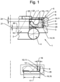
- the figure shows a sealing arrangement according to the invention during its intended use.
- the sealing arrangement is used in a bicycle electric motor.
- the sealing ring is designed to seal radially on the inside.
- the sealing ring 6 is mounted in a rotationally fixed manner in the outer ring 3 of the rolling bearing 1 and, with its sealing lip 7, forms a dynamic radial seal on the running surface 23 of the inner ring 2.
- the sealing arrangement comprises a ball bearing designed as a rolling bearing 1 with the inner ring 2, the outer ring 3 and rolling elements 4, which are designed as balls.
- the seal 5 which comprises the sealing ring 6 made of a rubber-elastic sealing material.
- the sealing ring 6 comprises the dynamically stressed sealing lip 7 and the statically stressed sealing area 8, whereby the sealing lip 7 and the sealing area 8 are integrally formed and made of the same material.
- the sealing area 8 has the sealing surface 9 on the side facing away from the sealing lip 7, with which the sealing area 8 is in the Stop ring 10 is arranged.
- the stop ring 10 is designed as an angle ring 11.
- the stop ring 10 consists of a tough material, for example sheet metal.
- the angle ring 11 is essentially L-shaped and comprises the axial flange 12 and the radial flange 13, whereby the axial flange 12 is pressed into the outer ring 3.
- the outer ring 3 is provided with an axial stop 15 against which the end face 14 of the axial flange 12 rests.
- the installation space of the sealing ring 6 is limited in the axial direction by the radial flange 13 of the angle ring 11 and the axial stop 15 of the outer ring 3.
- the sealing area is enclosed in a clamp-like manner by the angle ring 11 and the axial stop 15, as shown here.
- the radial depth 17 of the axial stop 15 is significantly greater than the radial thickness 16 of the axial flange 12. In the embodiment shown, the ratio of the radial depth 17 and the radial thickness 16 is approximately 2.
- the axial stop 15 in the outer ring 3 not only serves as an assembly aid, namely to form a stop for the angle ring 11 so that the seal 5 is always correctly positioned in relation to the rolling bearing 1 within the sealing arrangement.
- the axial flange 15 is statically sealed radially inside the axial flange 12 by the sealing area 8.
- the sealing ring 6 and the angle ring 11 form the pre-assembled unit 18, and the sealing ring 6 and the angle ring 11 are assigned to each other in a non-adhesive and force-locking manner.
- the axial mobility of the sealing ring 6 is limited by the radial flange 13 and the axial stop 15.
- the sealing arrangement is designed such that the rolling elements 4 are arranged on the side axially facing the seal 5 in the first imaginary radial plane 19 and the axial stop 12 and the end face of the sealing ring 6 axially facing the rolling elements 4 in the second imaginary radial plane 20, wherein the two radial planes 19, 20 are adjacent to one another with a first axial distance 21.
- the protector ring 22 forming a component of the sealing arrangement.
- the protector ring 22 is functionally arranged upstream of the sealing lip 7, viewed axially in the direction in which the sealing arrangement is exposed to contamination and/or moisture.
- the protector ring 22 is fixed to the inner ring 2 and covers the sealing lip 7, which is curved axially in the direction of the protector ring 22, and its running surface 23 on the inner ring 2 in the radial direction.
- the radial projection by which the protector ring 22 projects beyond the inner ring 2 in the radial direction essentially corresponds to the radial thickness of the sealing lip 7.
- the sealing arrangement shown has excellent performance characteristics over a long service life, mainly because the dynamically stressed sealing lip 7 and the statically stressed sealing area 8 are protected by the protector ring 22 and the angle ring 11, which interacts with the axial stop 15. This also protects the rolling bearing 1.
- the sealing arrangement has a simple design with few parts and can be manufactured inexpensively.
Landscapes
- Engineering & Computer Science (AREA)
- General Engineering & Computer Science (AREA)
- Mechanical Engineering (AREA)
- Rolling Contact Bearings (AREA)
- Sealing Of Bearings (AREA)
Abstract
Dichtungsanordnung, umfassend ein Wälzlager (1) mit einem Innenring (2), einem Außenring (3) und Wälzkörpern (4), die zwischen dem Innenring (2) und dem Außenring (3) angeordnet sind und eine Dichtung (5), umfassend einen Dichtring (6) aus einem Dichtungswerkstoff, mit einer dynamisch beanspruchten Dichtlippe (7) und einem statisch beanspruchten Dichtbereich (8), der eine Dichtfläche (9) auf der der Dichtlippe (7) radial abgewandten Seite aufweist, wobei sich die Dichtlippe (7) und der Dichtbereich (8) mit radialem Abstand benachbart zugeordnet sind und einen Anschlagring (10) aus einem zähharten Werkstoff, der die Dichtfläche (9) anliegend und dichtend berührt, wobei der Anschlagring (10) als Winkelring (11) mit einem Axialflansch (12) und einem Radialflansch (13) ausgebildet ist, wobei der Axialflansch (12) am Außen- (3) oder Innenring (2) festgelegt ist und auf der dem Radialflansch (13) axial abgewandten Seite eine Stirnseite (14) aufweist, die einen Axialanschlag (15) des Außen- (3) oder Innenrings (2) anliegend berührt.
Description
- Die Erfindung betrifft eine Dichtungsanordnung und deren Verwendung.
- Dichtungsanordnungen sind in unterschiedlichsten Ausführungen bekannt und gelangen in vielen Bereichen zur Anwendung, zum Beispiel zur Abdichtung von Elektromotoren.
- Der Erfindung liegt die Aufgabe zu Grunde, eine Dichtungsanordnung zur Abdichtung von Wälzlagern derart weiterzuentwickeln, dass sie einfach montierbar und einfach und kostengünstig herstellbar ist und gute Gebrauchseigenschaften während einer langen Gebrauchsdauer aufweist. Insbesondere sollen dynamisch beanspruchte und statisch beanspruchte Dichtstellen in der Dichtungsanordnung vor dem Eindringen von Verunreinigungen und Feuchtigkeit geschützt werden.
- Diese Aufgabe wird erfindungsgemäß durch eine Dichtungsanordnung mit den Merkmalen von Anspruch 1 und eine Verwendung gemäß Anspruch 9 gelöst. Auf vorteilhafte Ausgestaltungen der Dichtungsanordnung nehmen die auf Anspruch 1 direkt oder indirekt rückbezogenen Ansprüche Bezug.
- Zur Lösung der Aufgabe ist eine Dichtungsanordnung vorgesehen, umfassend ein Wälzlager mit einem Innenring, einem Außenring und Wälzkörpern, die zwischen dem Innenring und dem Außenring angeordnet sind und eine Dichtung, umfassend einen Dichtring aus einem Dichtungswerkstoff, mit einer dynamisch beanspruchten Dichtlippe und einem statisch beanspruchten Dichtbereich, der eine Dichtfläche auf der der Dichtlippe radial abgewandten Seite aufweist, wobei sich die Dichtlippe und der Dichtbereich mit radialem Abstand benachbart zugeordnet sind und einen Anschlagring aus einem zähharten Werkstoff, der die Dichtfläche anliegend und dichtend berührt, wobei der Anschlagring als Winkelring mit einem Axialflansch und einem Radialflansch ausgebildet ist, wobei der Axialflansch am Außen- oder Innenring festgelegt ist und auf der dem Radialflansch axial abgewandten Seite eine Stirnseite aufweist, die eine Axialanschlag des Außen- oder Innenrings anliegend berührt.
- Hierbei ist von Vorteil, dass die Montage der Dichtungsanordnung besonders einfach und prozesssicher durchführbar ist. Der Dichtring und der Anschlagring werden zunächst vormontiert. Anschließend wird die vormontierte Einheit in den Außen- oder Innenring des Wälzlagers so lange eingepresst, bis der Axialflansch mit seiner Stirnseite den Axialanschlag des Außen- oder Innenrings anliegend berührt.
- Generell besteht die Möglichkeit, dass die Dichtlippe des Dichtrings, in radialer Richtung betrachtet, innen- oder außendichtend ausgebildet, abhängig von den jeweiligen Gegebenheiten des Anwendungsfalls.
- Der Dichtring und der Anschlagring sind stets optimal im entsprechenden Ring des Wälzlagers positioniert
- Die Dichtungsanordnung hat einen einfachen und teilnahmen Aufbau und ist einfach und kostengünstig herstellbar.
- Gemäß einer vorteilhaften Ausgestaltung kann es vorgesehen sein, dass der Radialflansch und der Axialanschlag den Dichtbereich, im Querschnitt der Dichtungsanordnung betrachtet, klammerförmig umschließen. Der Dichtring kann sich dadurch, wenn überhaupt, nur innerhalb der klammerförmigen Umschließung in axialer Richtung bewegen. In axialer Richtung einerseits ist die Beweglichkeit des Dichtrings durch den Radialflansch des Anschlagrings, in axialer Richtung andererseits durch den Axialanschlag des entsprechenden Rings des Wälzlagers begrenzt.
- Der Axialflansch kann eine radiale Dicke und der Axialanschlag eine radiale Tiefe aufweisen, wobei das Verhältnis aus radialer Tiefe und radialer Dicke bevorzugt 1,5 bis 2,5 beträgt. Hierbei ist von Vorteil, dass sich durch das genannte Verhältnis eine deutliche Überdeckung des Axialflanschs in radialer Richtung durch den Axialanschlag ergibt. Dadurch, dass die radiale Tiefe stets deutlich größer als die radiale Dicke ist, legt sich die Stirnseite des Anschlagrings stets definiert und sauber an den Axialanschlag an. Zusätzlich überdeckt der Axialanschlag den Axialflansch in radialer Richtung so deutlich, dass gegebenenfalls ein axiales Wandern des Dichtrings in axialer Richtung durch den über den Axialflansch überstehenden Axialanschlag zuverlässig und sicher begrenzt würde.
- Bevorzugt bilden der Dichtring und der Winkelring eine vormontierte Einheit. Hierbei ist von Vorteil, dass sich dadurch die Montage der Dichtung im entsprechenden Ring des Wälzlagers vereinfacht. Während der Montage braucht lediglich die vormontierte Einheit mit dem entsprechenden Ring des Wälzlagers verbunden zu werden. Die Montage vieler Einzelteile und deren korrekte Positionierung relativ zueinander ist dadurch nicht erforderlich.
- Der Dichtring und der Winkelring können einander ungehaftet und kraftschlüssig zugeordnet sein. Auch eine derartige Ausgestaltung trägt zur einfachen und kostengünstigen Herstellbarkeit der Dichtungsanordnung bei. Außerdem ist von Vorteil, dass im Anschluss an die bestimmungsgemäße Verwendung der Dichtungsanordnung ein sortenreines Recycling durch die ungehaftete Zuordnung von Dichtring und Winkelring begünstigt wird.
- Die Wälzkörper können auf der der Dichtung axial zugewandten Seite in einer ersten gedachten Radialebene angeordnet sein und der Axialanschlag in einer zweiten gedachten Radialebene, wobei sich die Radialebenen mit einem ersten axialen Abstand benachbart zugeordnet sind. Während der bestimmungsgemäßen Verwendung der Dichtungsanordnung sind sich der Dichtring mit seiner Dichtlippe und die Wälzkörper stets mit axialem Abstand benachbart zugeordnet. Es gibt keinen unerwünschten Kontakt zwischen der Dichtung und den Wälzkörpern.
- Weiter verbesserte Gebrauchseigenschaften während einer langen Gebrauchsdauer weist die Dichtungsanordnung dadurch auf, dass die Dichtung bevorzugt einen Protektorring umfasst, der am Innen- oder Außenring festgelegt ist, wobei die Dichtlippe axial in Richtung Protektorring vorgewölbt ist und wobei der Protektorring die Dichtlippe und ihre entsprechende Lauffläche am Innen- oder Außenring in radialer Richtung überdeckt. Der Protektorring schützt die dynamisch beanspruchte Dichtlippe des Dichtrings. Der Protektorring schützt insbesondere vor einer Beaufschlagung der Dichtlippe mit Schmutz oder dann, wenn die Dichtungsanordnung mittels eines Wasserstrahls von außen gereinigt wird. Durch den Schutz der Dichtlippe durch den Protektorring wird die Lebensdauer des Dichtrings selbst und dadurch auch die Lebensdauer des durch den Dichtring geschützten Wälzlagers signifikant verlängert.
- Der Protektorring ist der Dichtlippe dazu bevorzugt mit einem zweiten axialen Abstand benachbart zugeordnet. Eine gegenseitige Berührung von Protektorring und Dichtlippe, die während der bestimmungsgemäßen Verwendung der Dichtungsanordnung relativ verdrehbar zueinander angeordnet sind, ist dadurch ausgeschlossen.
- Außerdem betrifft die Erfindung die Verwendung der zuvor beschriebenen Dichtungsanordnung. Für manche Verwendungen sind kompakte Abmessungen einer Dichtungsanordnung von Vorteil, und der Schutz der abgedichteten Wälzlager ist besonders wichtig.
- Erfindungsgemäß wird die Dichtungsanordnung in einem E-Motor verwendet, insbesondere in einem E-Motor für Fahrräder.
- Besonders E-Motoren für Fahrräder sollten kompakte Abmessungen aufweisen, dadurch nur ein geringes Gewicht, kostengünstig herstellbar sein und eine lange Lebensdauer auch dann aufweisen, wenn das Fahrrad im Freien abgestellt und/ oder auch unter widrigen Verhältnissen auf staubigen oder nassen und schlammigen Straßen gefahren wird.
- Dadurch, dass bei der erfindungsgemäßen Dichtungsanordnung sowohl die dynamisch beanspruchte Dichtlippe als auch der statische Dichtbereich gut vor einer Beaufschlagung mit Verunreinigungen und Feuchtigkeit geschützt sind, ist selbst die Reinigung des Fahrrads mittels eines Wasserstrahls unbedenklich. Die Dichtstellen der Dichtungsanordnung und das Wälzlager in der Dichtungsanordnung sind gut selbst vor solchen äußeren Einflüssen geschützt.
- Ein Ausführungsbeispiel der erfindungsgemäßen Dichtungsanordnung wird nachfolgend anhand der Figur näher erläutert.
- Diese zeigt eine Dichtungsanordnung in schematischer Darstellung während einer bestimmungsgemäßen Verwendung.
- In der Figur ist eine erfindungsgemäße Dichtungsanordnung während ihrer bestimmungsgemäßen Verwendung gezeigt.
- Verwendet wird die Dichtungsanordnung in einem Fahrrad-Elektromotor.
- In dem gezeigten Ausführungsbeispiel ist der Dichtring radial innendichtend ausgebildet.
- Der Dichtring 6 ist drehfest im Außenring 3 des Wälzlagers 1 montiert und dichtet mit seiner Dichtlippe 7 radial innen dynamisch dichtend auf der Lauffläche 23 des Innenrings 2 ab.
- Die Dichtungsanordnung umfasst ein als Wälzlager 1 ausgebildetes Kugellager mit dem Innenring 2, dem Außenring 3 und Wälzkörpern 4, die als Kugeln ausgebildet sind.
- Um das Wälzlager 1 vor dem Eindringen von Verunreinigungen und Feuchtigkeit zu schützen, ist die Dichtung 5 vorgesehen, die den Dichtring 6 aus einem gummielastischen Dichtungswerkstoff umfasst. Der Dichtring 6 umfasst in diesem Ausführungsbeispiel die dynamisch beanspruchte Dichtlippe 7 und den statisch beanspruchten Dichtbereich 8, wobei die Dichtlippe 7 und der Dichtbereich 8 einstückig ineinander übergehend und materialeinheitlich ausgebildet sind. Der Dichtbereich 8 weist auf der der Dichtlippe 7 radial abgewandten Seite die Dichtfläche 9 auf, mit der der Dichtbereich 8 im Anschlagring 10 angeordnet ist. Der Anschlagring 10 ist als Winkelring 11 ausgebildet. Der Anschlagring 10 besteht aus einem zähharten Werkstoff, zum Beispiel aus Blech. Der Winkelring 11 ist im Wesentlichen L-förmig ausgebildet und umfasst den Axialflansch 12 und den Radialflansch 13, wobei der Axialflansch 12 im Außenring 3 eingepresst ist. Der Außenring 3 ist mit einem Axialanschlag 15 versehen, an dem die Stirnseite 14 des Axialflanschs 12 anliegt.
- Durch den Radialflansch 13 des Winkelrings 11 und den Axialanschlag 15 des Außenrings 3 ist der Einbauraum des Dichtrings 6 in axialer Richtung begrenzt. Durch den Winkelring 11 und den Axialanschlag 15 ist der Dichtbereich, wie hier gezeigt, klammerförmig umschlossen.
- Die radiale Tiefe 17 des Axialanschlags 15 ist deutlich größer, als die radiale Dicke 16 des Axialflanschs 12. Im gezeigten Ausführungsbeispiel ist das Verhältnis aus der radialen Tiefe 17 und der radialen Dicke 16 etwa 2.
- Der Axialanschlag 15 im Außenring 3 hat nicht nur die Aufgabe einer Montagehilfe, nämlich einen Anschlag für den Winkelring 11 zu bilden, so dass die Dichtung 5 bezogen auf das Wälzlager 1 innerhalb der Dichtungsanordnung stets korrekt positioniert ist. Außerdem bildet der Axialanschlag 15 mit seiner im Vergleich zur Dicke 16 des Axialflanschs 12 größeren radialen Tiefe 17 einen zusätzlichen Schmutzfang, durch den noch besser verhindert wird, dass Verunreinigungen und/ oder Feuchtigkeit zu den Wälzkörpern 4 vordringen. Der Axialflansch 15 wird radial innen des Axialflanschs 12 durch den Dichtbereich 8 statisch abgedichtet.
- Der Dichtring 6 und der Winkelring 11 bilden die vormontierte Einheit 18, und der Dichtring 6 und der Winkelring 11 sind einander ungehaftet und kraftschlüssig zugeordnet. Die axiale Beweglichkeit des Dichtrings 6 ist durch den Radialflansch 13 und den Axialanschlag 15 begrenzt.
- Um sicherzustellen, dass die Wälzkörper 4 und der Dichtring 6 während der bestimmungsgemäßen Verwendung der Dichtungsanordnung stets ohne Kontakt zueinander sind, ist die Dichtungsanordnung derart ausgebildet, dass die Wälzkörper 4 auf der der Dichtung 5 axial zugewandten Seite in der ersten gedachten Radialebene 19 angeordnet sind und der Axialanschlag 12 und die den Wälzkörpern 4 axial zugewandte Stirnseite des Dichtrings 6 in der zweiten gedachten Radialebene 20, wobei sich die beiden Radialebenen 19, 20 mit einem ersten axialen Abstand 21 benachbart zugeordnet sind.
- Ein weiter verbesserter Schutz des Dichtrings 6, insbesondere der Dichtlippe 7, wird dadurch erreicht, dass der Protektorring 22 einen Bestandteil der Dichtungsanordnung bildet. Der Protektorring 22 ist der Dichtlippe 7, axial in Richtung der Beaufschlagung der Dichtungsanordnung mit Verunreinigungen und/ oder Feuchtigkeit betrachtet, funktionstechnisch vorgeschaltet. Der Protektorring 22 ist am Innenring 2 festgelegt und überdeckt die axial in Richtung Protektorring 22 vorgewölbte Dichtlippe 7 und deren Lauffläche 23 auf dem Innenring 2 in radialer Richtung.
- Der radiale Überstand, mit dem der Protektorring 22 den Innenring 2 in radialer Richtung überragt, entspricht im Wesentlichen der radialen Dicke der Dichtlippe 7.
- Die gezeigte Dichtungsanordnung weist ausgezeichnete Gebrauchseigenschaften während einer langen Gebrauchsdauer auf, hauptsächlich dadurch, dass die dynamisch beanspruchte Dichtlippe 7 und der statisch beanspruchte Dichtbereich 8 durch den Protektorring 22 und den Winkelring 11, der mit dem Axialanschlag 15 zusammenwirkt, geschützt sind. Dadurch ist gleichermaßen auch das Wälzlager 1 geschützt. Außerdem weist die Dichtungsanordnung einen teilearmen und einfachen Aufbau auf und ist kostengünstig herstellbar.
- Die gezeigte Ausschnittsvergrößerung ist mit Bezugszeichen 25 versehen.
Claims (9)
- Dichtungsanordnung, umfassend ein Wälzlager (1) mit einem Innenring (2), einem Außenring (3) und Wälzkörpern (4), die zwischen dem Innenring (2) und dem Außenring (3) angeordnet sind und eine Dichtung (5), umfassend einen Dichtring (6) aus einem Dichtungswerkstoff, mit einer dynamisch beanspruchten Dichtlippe (7) und einem statisch beanspruchten Dichtbereich (8), der eine Dichtfläche (9) auf der der Dichtlippe (7) radial abgewandten Seite aufweist, wobei sich die Dichtlippe (7) und der Dichtbereich (8) mit radialem Abstand benachbart zugeordnet sind und einen Anschlagring (10) aus einem zähharten Werkstoff, der die Dichtfläche (9) anliegend und dichtend berührt, wobei der Anschlagring (10) als Winkelring (11) mit einem Axialflansch (12) und einem Radialflansch (13) ausgebildet ist, wobei der Axialflansch (12) am Außen- (3) oder Innenring (2) festgelegt ist und auf der dem Radialflansch (13) axial abgewandten Seite eine Stirnseite (14) aufweist, die einen Axialanschlag (15) des Außen- (3) oder Innenrings (2) anliegend berührt.
- Dichtungsanordnung nach Anspruch 1, dadurch gekennzeichnet, dass der Radialflansch (13) und der Axialanschlag (12) den Dichtbereich (8), im Querschnitt der Dichtungsanordnung betrachtet, klammerförmig umschließen.
- Dichtungsanordnung nach einem der Ansprüche 1 oder 2, dadurch gekennzeichnet, dass der Axialflansch (12) eine radiale Dicke (16) und der Axialanschlag (15) eine radiale Tiefe (17) aufweisen und dass das Verhältnis aus radialer Tiefe (17) und radialer Dicke (16) 1,5 bis 2,5 beträgt.
- Dichtungsanordnung nach einem der Ansprüche 1 bis 3, dadurch gekennzeichnet, dass der Dichtring (6) und der Winkelring (11) eine vormontierte Einheit (18) bilden.
- Dichtungsanordnung nach Anspruch 4, dadurch gekennzeichnet, dass der Dichtring (6) und der Winkelring (11) einander ungehaftet und kraftschlüssig zugeordnet sind.
- Dichtungsanordnung nach Anspruch 1, dadurch gekennzeichnet, dass die Wälzkörper (4) auf der der Dichtung (5) axial zugewandten Seite in einer ersten gedachten Radialebene (19) angeordnet sind und der Axialanschlag (12) in einer zweiten gedachten Radialebene (20) und dass sich die Radialebenen (19, 20) mit einem ersten axialen Abstand (21) benachbart zugeordnet sind.
- Dichtungsanordnung nach Anspruch 1, dadurch gekennzeichnet, dass die Dichtung (5) einen Protektorring (22) umfasst, der am Innen- (2) oder Außenring (3) festgelegt ist, dass die Dichtlippe (7) axial in Richtung Protektorring (22) vorgewölbt ist und dass der Protektorring (22) die Dichtlippe (7) und ihre entsprechende Lauffläche am Innen- (2) oder Außenring (3) in radialer Richtung überdeckt.
- Dichtungsanordnung nach Anspruch 7, dadurch gekennzeichnet, dass der Protektorring (22) der Dichtlippe (7) mit einem zweiten axialen Abstand (24) benachbart zugeordnet ist.
- Verwendung einer Dichtungsanordnung nach einem der Ansprüche 1 bis 8 in einem Elektromotor.
Applications Claiming Priority (1)
| Application Number | Priority Date | Filing Date | Title |
|---|---|---|---|
| DE102023102555.4A DE102023102555A1 (de) | 2023-02-02 | 2023-02-02 | Dichtungsanordnung und deren Verwendung |
Publications (1)
| Publication Number | Publication Date |
|---|---|
| EP4411160A1 true EP4411160A1 (de) | 2024-08-07 |
Family
ID=89536036
Family Applications (1)
| Application Number | Title | Priority Date | Filing Date |
|---|---|---|---|
| EP24150623.7A Withdrawn EP4411160A1 (de) | 2023-02-02 | 2024-01-08 | Dichtungsanordnung und deren verwendung |
Country Status (2)
| Country | Link |
|---|---|
| EP (1) | EP4411160A1 (de) |
| DE (1) | DE102023102555A1 (de) |
Citations (2)
| Publication number | Priority date | Publication date | Assignee | Title |
|---|---|---|---|---|
| US3584924A (en) * | 1968-12-26 | 1971-06-15 | Federal Mogul Corp | Seal and bearing assembly |
| JPS57107022U (de) * | 1980-12-23 | 1982-07-01 |
Family Cites Families (7)
| Publication number | Priority date | Publication date | Assignee | Title |
|---|---|---|---|---|
| US1963704A (en) | 1932-05-28 | 1934-06-19 | Chicago Rawhide Mfg Co | Sealing means |
| US2173247A (en) | 1937-11-13 | 1939-09-19 | Norma Hoffman Bearings Corp | Seal for ball bearings |
| US2747949A (en) | 1953-04-15 | 1956-05-29 | Mcgill Mfg Company Inc | Self-contained seal and bearing assembly |
| US2866670A (en) | 1955-06-16 | 1958-12-30 | Transall Inc | Seal for anti-friction bearings and the like |
| US3012829A (en) | 1958-06-30 | 1961-12-12 | Fmc Corp | Fluid seal |
| US4392695A (en) | 1981-08-10 | 1983-07-12 | Miller Manufacturing Company | Bearing |
| US5704719A (en) | 1996-07-01 | 1998-01-06 | Emerson Power Transmission Corp. | Street sweeper bearing with wear resistant resiliently biased face seal |
-
2023
- 2023-02-02 DE DE102023102555.4A patent/DE102023102555A1/de not_active Ceased
-
2024
- 2024-01-08 EP EP24150623.7A patent/EP4411160A1/de not_active Withdrawn
Patent Citations (2)
| Publication number | Priority date | Publication date | Assignee | Title |
|---|---|---|---|---|
| US3584924A (en) * | 1968-12-26 | 1971-06-15 | Federal Mogul Corp | Seal and bearing assembly |
| JPS57107022U (de) * | 1980-12-23 | 1982-07-01 |
Also Published As
| Publication number | Publication date |
|---|---|
| DE102023102555A1 (de) | 2024-08-08 |
Similar Documents
| Publication | Publication Date | Title |
|---|---|---|
| EP0431263B1 (de) | Kassettendichtung | |
| DE3838824C2 (de) | Dichtung, bestehend aus mehreren Dichtringen | |
| DE102010064672B3 (de) | Dichtungsanordnung zur Abdichtung eines Radlagers | |
| DE10125253B4 (de) | Dichtvorrichtung für Flanschlager | |
| DE69616634T2 (de) | Lagerdichtung | |
| DE2938393A1 (de) | Labyrinth-dichtungselement und unter verwendung solcher labyrinth-dichtungselemente hergestellte labyrinth-dichtungen | |
| DE102023201191A1 (de) | Lageranordnung für Lebensmittelanwendungen | |
| DE112018001577T5 (de) | Radlagervorrichtung | |
| DE102023102555A1 (de) | Dichtungsanordnung und deren Verwendung | |
| DE102012208055B4 (de) | Lageranordnung, insbesondere ein Antriebswellenstützlager für ein Kraftfahrzeug | |
| DE102018105832A1 (de) | Kassettendichtung mit Doppellabyrinth und Fliehkraftdichtung | |
| DE19652001A1 (de) | Verbesserung an einem integrierten Dichtungssystem für automatische Getriebe | |
| EP1477694B1 (de) | Dichtungsanordnung zur Abdichtung eines Spalts zwischen einer Lagerbüchse und einem Zapfen | |
| EP2935915B1 (de) | Gelenkeinrichtung für ein kraftfahrzeug | |
| DE102009019396B4 (de) | Dichtungsanordnung für eine Wälzlagerung | |
| DE4123688A1 (de) | Wellendichtring | |
| EP2290271A1 (de) | Dichtungsanordnung und deren Verwendung | |
| DE102005039741A1 (de) | Abdichtung für eine in einem Gehäuse gelagerte Welle beziehungsweise für ein Wälzlager | |
| EP0006995B1 (de) | Dichtungsring | |
| DE102021131523A1 (de) | Dichtanordnung für ein Lager sowie Lager mit einer solchen Dichtanordnung | |
| DE4203391A1 (de) | Dichtungsanordnung fuer eine wasserpumpe einer brennkraftmaschine | |
| DE9014394U1 (de) | Abdichtung für Lager, insbesondere für Tretachslagerungen von Fahrrädern | |
| EP2239474A1 (de) | Dichteinrichtung mit Filter | |
| DE19955859B4 (de) | Gleitringdichtung | |
| DE3011135C2 (de) | Lippendichtung |
Legal Events
| Date | Code | Title | Description |
|---|---|---|---|
| PUAI | Public reference made under article 153(3) epc to a published international application that has entered the european phase |
Free format text: ORIGINAL CODE: 0009012 |
|
| STAA | Information on the status of an ep patent application or granted ep patent |
Free format text: STATUS: THE APPLICATION HAS BEEN PUBLISHED |
|
| AK | Designated contracting states |
Kind code of ref document: A1 Designated state(s): AL AT BE BG CH CY CZ DE DK EE ES FI FR GB GR HR HU IE IS IT LI LT LU LV MC ME MK MT NL NO PL PT RO RS SE SI SK SM TR |
|
| STAA | Information on the status of an ep patent application or granted ep patent |
Free format text: STATUS: THE APPLICATION IS DEEMED TO BE WITHDRAWN |
|
| 18D | Application deemed to be withdrawn |
Effective date: 20250208 |