EP4411035A1 - Yarn production system - Google Patents
Yarn production system Download PDFInfo
- Publication number
- EP4411035A1 EP4411035A1 EP23220477.6A EP23220477A EP4411035A1 EP 4411035 A1 EP4411035 A1 EP 4411035A1 EP 23220477 A EP23220477 A EP 23220477A EP 4411035 A1 EP4411035 A1 EP 4411035A1
- Authority
- EP
- European Patent Office
- Prior art keywords
- oil supply
- guide
- yarn
- bundling
- discharge port
- Prior art date
- Legal status (The legal status is an assumption and is not a legal conclusion. Google has not performed a legal analysis and makes no representation as to the accuracy of the status listed.)
- Pending
Links
- 238000004519 manufacturing process Methods 0.000 title claims abstract description 40
- 238000009987 spinning Methods 0.000 claims abstract description 51
- 238000001816 cooling Methods 0.000 claims description 46
- 230000033228 biological regulation Effects 0.000 claims description 23
- 229920000642 polymer Polymers 0.000 description 19
- 230000001105 regulatory effect Effects 0.000 description 15
- 238000004804 winding Methods 0.000 description 9
- 230000007423 decrease Effects 0.000 description 8
- JJLJMEJHUUYSSY-UHFFFAOYSA-L Copper hydroxide Chemical compound [OH-].[OH-].[Cu+2] JJLJMEJHUUYSSY-UHFFFAOYSA-L 0.000 description 4
- 230000000717 retained effect Effects 0.000 description 3
- 238000007664 blowing Methods 0.000 description 2
- 230000003247 decreasing effect Effects 0.000 description 2
- 238000012986 modification Methods 0.000 description 2
- 230000004048 modification Effects 0.000 description 2
- 239000007787 solid Substances 0.000 description 2
- 239000000919 ceramic Substances 0.000 description 1
- 230000000694 effects Effects 0.000 description 1
- 230000005484 gravity Effects 0.000 description 1
- 239000000463 material Substances 0.000 description 1
- 238000009985 spun yarn production Methods 0.000 description 1
Images




Classifications
-
- D—TEXTILES; PAPER
- D01—NATURAL OR MAN-MADE THREADS OR FIBRES; SPINNING
- D01D—MECHANICAL METHODS OR APPARATUS IN THE MANUFACTURE OF ARTIFICIAL FILAMENTS, THREADS, FIBRES, BRISTLES OR RIBBONS
- D01D5/00—Formation of filaments, threads, or the like
- D01D5/08—Melt spinning methods
- D01D5/088—Cooling filaments, threads or the like, leaving the spinnerettes
-
- D—TEXTILES; PAPER
- D01—NATURAL OR MAN-MADE THREADS OR FIBRES; SPINNING
- D01D—MECHANICAL METHODS OR APPARATUS IN THE MANUFACTURE OF ARTIFICIAL FILAMENTS, THREADS, FIBRES, BRISTLES OR RIBBONS
- D01D13/00—Complete machines for producing artificial threads
- D01D13/02—Elements of machines in combination
-
- D—TEXTILES; PAPER
- D01—NATURAL OR MAN-MADE THREADS OR FIBRES; SPINNING
- D01D—MECHANICAL METHODS OR APPARATUS IN THE MANUFACTURE OF ARTIFICIAL FILAMENTS, THREADS, FIBRES, BRISTLES OR RIBBONS
- D01D5/00—Formation of filaments, threads, or the like
- D01D5/08—Melt spinning methods
- D01D5/088—Cooling filaments, threads or the like, leaving the spinnerettes
- D01D5/092—Cooling filaments, threads or the like, leaving the spinnerettes in shafts or chimneys
-
- D—TEXTILES; PAPER
- D01—NATURAL OR MAN-MADE THREADS OR FIBRES; SPINNING
- D01D—MECHANICAL METHODS OR APPARATUS IN THE MANUFACTURE OF ARTIFICIAL FILAMENTS, THREADS, FIBRES, BRISTLES OR RIBBONS
- D01D5/00—Formation of filaments, threads, or the like
- D01D5/08—Melt spinning methods
- D01D5/096—Humidity control, or oiling, of filaments, threads or the like, leaving the spinnerettes
Definitions
- the present invention relates to a yarn production system structured so that filaments are spun out downward from a single spinneret, divided into two groups, and bundled as two yarns.
- a known yarn production system includes (i) a spinning apparatus configured to spin out yarns downward from spinnerets provided at a lower end portion of the spinning apparatus and (ii) an oiling unit configured to apply oil to the yarns spun out from the spinning apparatus.
- Each spinneret is provided with discharge ports through which filaments are spun out. The filaments spun out through the discharge ports are bundled as yarns.
- Patent Literature 1 Japanese Laid-Open Patent Publication No. 2010-196219 discloses that filaments are spun out downward from a single spinneret, divided into plural (e.g., two) groups, and bundled as plural (e.g., two) yarns in order to improve the production efficiency.
- a cooler is provided below the spinneret, and an oiling unit (an oiling nozzle unit of Patent Literature 1) is provided below the cooler in order to apply oil to the yarns.
- the cooler is structured so that the filaments spun out from the spinneret are blown by cooling wind from their surroundings.
- the oiling unit includes oil supply guides to which the respective groups of filaments spun out from the spinneret are threaded.
- filaments spun out downward from the spinneret are simultaneously cooled by means of the cooling wind from the cooler.
- the filaments are then divided into groups each of which forms a yarn and to which oil is applied by the respective oil supply guides. That is, the filaments spun out from the spinneret are divided into filament groups each of which is formed of filaments forming a yarn, and then the filament groups run toward the respective oil supply guides.
- the filament groups spun out from the spinneret respectively run toward different oil supply guides.
- a space is formed between the filament groups running from the spinneret to the respective oil supply guides.
- the cooling wind enters the space from the cooler, the disturbance of airflows occurs in the space. This disturbs the cooling wind blowing the filaments, and thus each filament is easily cooled at some parts and improperly cooled at other parts in a circumferential direction of the filament. Because of this, the filaments are unevenly cooled by means of the cooling wind. As a result, the quality of yarns formed of the filaments is deteriorated.
- An object of the present invention is to properly cool filaments in a structure in which the filaments are spun out downward from a single spinneret, divided into two groups, and bundled as two yarns.
- a yarn production system of the present invention comprises: a spinning apparatus including a spinneret provided with discharge ports through which filaments are spun out downward; a cooler which is provided below the spinneret and which is configured to cool the filaments by means of cooling wind; and an oiling unit which is provided below the cooler and which is configured to apply oil to a first yarn and a second yarn.
- the filaments are divided into two groups and bundled as the first yarn and the second yarn
- the discharge ports are divided into a first discharge port group through which filaments forming the first yarn are spun out and a second discharge port group through which filaments forming the second yarn are spun out, by a virtual partitioning plane extending in a vertical direction and a predetermined width direction intersecting with the vertical direction.
- the oiling unit includes: a first oil supply guide including a first oil supply surface with which a running first filament group formed of the filaments forming the first yarn makes contact and a pair of first yarn guiding members provided on both sides of the first oil supply surface in a horizontal direction to guide the first filament group toward the first oil supply surface; and a second oil supply guide including a second oil supply surface with which a running second filament group formed of the filaments forming the second yarn makes contact and a pair of second yarn guiding members provided on both sides of the second oil supply surface in the horizontal direction to guide the second filament group toward the second oil supply surface.
- the yarn production system further comprises: a first bundling guide which is provided below the cooler and above the oiling unit and to which the first filament group is threaded; and a second bundling guide which is provided below the cooler and above the oiling unit and to which the second filament group is threaded.
- the distance between the first bundling guide and the second bundling guide in the horizontal direction is shorter than (i) the distance between the first oil supply guide and the second oil supply guide and (ii) the distance between the barycentric position of the first discharge port group and the barycentric position of the second discharge port group in the horizontal direction
- the first oil supply guide is provided on the same side as the first discharge port group with respect to the virtual partitioning plane when viewed in the vertical direction
- the second oil supply guide is provided on the same side as the second discharge port group with respect to the virtual partitioning plane when viewed in the vertical direction
- the first oil supply surface extends in an up-down direction and a predetermined first width direction which is the horizontal direction
- the second oil supply surface extends in the up-down direction and a predetermined second width direction which is the horizontal direction, when an angle between the first width direction and the virtual partitioning plane viewed in the vertical direction is 0 degree in a case where (i) the first width direction is in parallel to the virtual partitioning plane and (ii) the first oil supply
- the first width direction is inclined from the virtual partitioning plane at 90 degrees clockwise.
- the first width direction is inclined from the virtual partitioning plane at 90 degrees counterclockwise.
- the second width direction is inclined from the virtual partitioning plane at 90 degrees clockwise.
- the second width direction is inclined from the virtual partitioning plane at 90 degrees counterclockwise.
- the first filament group spun out from the spinneret is threaded to the first bundling guide provided above the oiling unit
- the second filament group spun out from the spinneret is threaded to the second bundling guide provided above the oiling unit.
- the distance between the first bundling guide and the second bundling guide is shorter than (i) the distance between the first oil supply guide and the second oil supply guide and (ii) the distance between the barycentric position of the first discharge port group and the barycentric position of the second discharge port group.
- the first oil supply guide is provided on the same side as the first discharge port group with respect to the virtual partitioning plane
- the second oil supply guide is provided on the same side as the second discharge port group with respect to the virtual partitioning plane. That is, the virtual partitioning plane is provided between the first oil supply guide and the second oil supply guide.
- each of (i) the angle between the first width direction and the virtual partitioning plane and (ii) the angle between the second width direction and the virtual partitioning plane is within the range of 90 to -90 degrees. That is, the first oil supply surface does not face the virtual partitioning plane. The same applies to the second oil supply surface.
- the first discharge port group is arranged so that (i) discharge ports belonging to the first discharge port group form at least one first line extending in the predetermined width direction and at least one second line extending in a direction intersecting with the predetermined width direction, (ii) one of the at least one first line has more discharge ports than the at least one first line, (iii) one of the at least one second line has more discharge ports than the at least one second line, and (iv) the one of the at least one first line is larger than the one of the at least one second line in terms of the number of the discharge ports, and the second discharge port group is arranged so that (i) discharge ports belonging to the second discharge port group form at least one first line extending in the predetermined width direction and at least one second line extending in the direction intersecting with the predetermined width direction, (ii) one of the at least one first line has more discharge ports than the at least one first line, (iii) one of the at least one second line has more discharge ports than the
- each of the first discharge port group and the second discharge port group is arranged so that (i) discharge ports belonging to the first discharge port group form at least one first line extending in the predetermined width direction and at least one second line extending in the direction intersecting with the predetermined width direction, (ii) one of the at least one first line has more discharge ports than the at least one first line, (iii) one of the at least one second line has more discharge ports than the at least one second line, and (iv) the one of the at least one first line is larger than the one of the at least one second line in terms of the number of the discharge ports.
- each of (i) the angle between the first width direction and the virtual partitioning plane and (ii) the angle between the second width direction and the virtual partitioning plane is within the range of 45 to -45 degrees.
- an angle between a direction in which the filaments spun out from the first discharge port group are most widely dispersed (i.e., the predetermined width direction) and the first width direction of the first oil supply surface is arranged to be as small as possible.
- an angle between a direction in which the filaments spun out from the second discharge port group are most widely dispersed (i.e., the predetermined width direction) and the second width direction of the second oil supply surface is arranged to be as small as possible.
- the first discharge port group and the second discharge port group are line-symmetric about the virtual partitioning plane
- the first bundling guide and the second bundling guide are line-symmetric about the virtual partitioning plane
- the first oil supply surface and the second oil supply surface are line-symmetric about the virtual partitioning plane.
- the filaments spun out from the two discharge port groups of the spinneret are cooled by means of the cooling wind supplied from the cooler provided between the spinning apparatus and the oiling unit.
- the following paths are plane-symmetric about the virtual partitioning plane: a path of the first filament group, which is spun out from the first discharge port group, to the first oil supply surface via the first bundling guide; and a path of the second filament group, which is spun out from the second discharge port group, to the second oil supply surface via the second bundling guide.
- the filaments spun out from the first discharge port group are identical with the filaments spun out from the second discharge port group in regard to the length of a path on which the filaments are blown by the cooling wind from the cooler provided between the spinning apparatus and the oiling unit. It is therefore possible to equalize the quality of the two yarns formed of the filaments spun out from the two discharge port groups of the spinneret.
- a take-up roller for taking up the first yarn and the second yarn is provided downstream of the oiling unit in a yarn running direction in which the first yarn and the second yarn run, the first bundling guide and the second bundling guide are movable between regulation positions and yarn threading positions, the first bundling guide is moved to one of the regulation positions when the first yarn is taken up by the take-up roller and to one of the yarn threading positions when the first filament group is threaded to the first bundling guide, the second bundling guide is moved to the other of the regulation positions when the second yarn is taken up by the take-up roller and to the other of the yarn threading positions when the second filament group is threaded to the second bundling guide, and the distance between the first bundling guide at the one of the yarn threading positions and the second bundling guide at the other of the yarn threading positions is longer than the distance between the first bundling guide at the one of the regulation positions and the second bundling guide at the other of the regulation
- the distance between the first bundling guide and the second bundling guide at the respective yarn threading positions is longer than the distance between the first bundling guide and the second bundling guide at the respective regulation positions.
- the first bundling guide and the second bundling guide are bar guides.
- the filament groups are easily threaded to the respective bundling guides by simply placing the filament groups along the bundling guides which are bar guides.
- each of the bar guides is rotatable about the axial center of the each of the bar guides, and the axial center of the each of the bar guides extends in an extending direction of the each of the bar guides.
- a friction force on the filaments in contact with each of the bundling guides is decreased by rotating the bundling guides which are the bar guides in accordance with the running of the filament groups threaded to the respective bundling guides. This suppresses the decrease in quality of the yarns formed of the respective filament groups.
- the distance between the first bundling guide and the second bundling guide is equal to or more than 1 mm and equal to or less than 10 mm.
- the filament groups threaded to the respective bundling guides may be tangled with one another. Meanwhile, when the distance between the first bundling guide and the second bundling guide is too long, the two filament groups cannot be bundled between the spinneret and the respective oil supply guides. This puts a limit on the decrease in size of a space formed between the two filament groups running between the spinneret and the respective oil supply guides.
- the present invention makes it possible to solve the above-described problem, to suppress the tangle of the filament groups threaded to the respective bundling guides, and to further decrease the size of a space formed between the two filament groups running between the spinneret and the respective oil supply guides.
- the cooler is an annular cooler in which the entire circumference of each of the running filaments is blown by the cooling wind.
- the annular cooler makes it possible to effectively suppress the disturbance of airflows caused by the inflow of the cooling wind from the cooler into the space. It is therefore possible to further properly cool the filaments.
- the first bundling guide and the second bundling guide are closer to the cooler than to the oiling unit in the vertical direction.
- the two filament groups running between the spinneret and the respective oil supply guides are temporarily bundled at a position closer to the cooler than to the respective oil supply guides in the vertical direction. This further decreases the size of a space formed between the two filament groups running from the spinneret to the respective bundling guides, i.e., between the two filament groups passing the cooler.
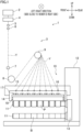
- FIG. 1 is a profile of a yarn production system 1 of the present embodiment.
- FIG. 2 is a partial cross section of a spinning apparatus 2 and a cooler 4.
- FIG. 3 is a bottom view of one spinneret 24.
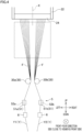
- FIG. 4 shows one of spinnerets 24 and an oiling unit 5 provided below the one of spinnerets 24.
- FIG. 5 is a perspective view of bundling guides 30.
- FIG. 6 is a top view of oil supply guides 51.
- FIG. 1 and FIG. 2 do not show the bundling guides 30.
- front-rear, left-right, and up-down directions in FIG. 1 will be referred to as front-rear, left-right, and up-down directions of the yarn production system 1.
- the up-down direction is a vertical direction of the present invention, and is a direction in which the gravity acts.
- the yarn production system 1 includes the spinning apparatus 2 and a spun yarn take-up apparatus 3.
- the spinning apparatus 2 is configured to spin out molten polymer downward as yarns Y.
- the spun yarn take-up apparatus 3 is configured to take up the yarns Y spun out from the spinning apparatus 2 and includes the cooler 4, oiling units 5, yarn path regulatory guides 6, a comb teeth guide 7, godet rollers 8 and 9, and a spun yarn take-up winding apparatus 10.
- the spinning apparatus 2 includes a spinning beam 21, spinning packs 22 attached to a housing formed at a lower portion of the spinning beam 21, and a polymer tank 23 housing polymer which is a material of the yarns Y.
- the spinning beam 21 is able to heat, e.g., (i) the spinning packs 22 provided therein, (ii) the polymer tank 23, and (iii) polymer pipes 25 connecting the spinning packs 22 to the polymer tank 23.
- the spinning beam 21 is rectangular in plan view and long in the left-right direction.
- the spinning packs 22 are staggered to form two lines with respect to the spinning beam 21 which is rectangular in plan view. In other words, the spinning packs 22 are provided to form two lines in the front-rear direction of the rectangular spinning beam 21 and, in the left-right direction, the positions of spinning packs 22 forming the front line are different from those of spinning packs 22 forming the rear line.
- Each spinning pack 22 stores molten polymer therein and has a spinneret 24 at its lower end portion.
- each spinneret 24 is configured to spin out (see FIG. 4 ) filaments F forming two yarns Y (hereinafter, these yarns Y may be referred to as a first yarn Y1 and a second yarn Y2).
- the spinneret 24 is substantially circular in shape when viewed from below.
- the diameter of the spinneret 24 is, e.g., 85 mm.
- discharge ports 26 are provided in order to spin out the filaments F downward.
- the discharge ports 26 are aligned in the front-rear direction and the left-right direction.
- each spinneret 24 is provided with 144 discharge ports 26.
- the molten polymer stored in each spinning pack 22 is spun out, as the filaments F, downward from the discharge ports 26 provided at the spinneret 24.
- the discharge ports 26 are divided into a first discharge port group 26A provided for spinning out filaments F forming the first yarn Y1 (see FIG. 4 ) and a second discharge port group 26B provided for spinning out filaments F forming the second yarn Y2 (see FIG. 4 ).
- a virtual partitioning plane X extending in the front-rear direction (a predetermined width direction of the present invention) and the up-down direction divides the discharge ports 26 into the first discharge port group 26A and the second discharge port group 26B (see FIG. 3 and FIG. 4 ). As shown in FIG.
- the first discharge port group 26A and the second discharge port group 26B are line-symmetric about the virtual partitioning plane X.
- the first discharge port group 26A is formed of 72 discharge ports 26.
- the first discharge port group 26A is arranged so that (i) discharge ports 26 belonging to the first discharge port group 26A form first lines extending along the front-rear direction and second lines extending in a direction (the left-rear direction, an oblique direction, or the like) intersecting with the front-rear direction, i.e., in a direction different from the front-rear direction, (ii) one of the first lines has more discharge ports 26 than the first lines, (iii) one of the second lines has more discharge ports 26 than the second lines, and (iv) the one of the first lines is larger than the one of the second lines in terms of the number of the discharge ports 26.
- the second discharge port group 26B is formed of 72 discharge ports 26. As shown in FIG. 3 , the second discharge port group 26B is arranged so that (i) discharge ports 26 belonging to the second discharge port group 26B form first lines extending along the front-rear direction and second lines extending in a direction (the left-rear direction, an oblique direction, or the like) intersecting with the front-rear direction, i.e., in a direction different from the front-rear direction, (ii) one of the first lines has more discharge ports 26 than the first lines, (iii) one of the second lines has more discharge ports 26 than the second lines, and (iv) the one of the first lines is larger than the one of the second lines in terms of the number of the discharge ports 26.
- the filaments F spun out from the first discharge port group 26A are bundled as the first yarn Y1.
- the filaments F spun out from the second discharge port group 26B are bundled as the second yarn Y2. That is, filaments F spun out from each spinneret 24 are divided into two groups and bundled as two yarns Y (the first yarn Y1 and the second yarn Y2).
- the polymer tank 23 is configured to store polymer therein, and the polymer in the polymer tank 23 is sent to the spinning packs 22 through the polymer pipes 25.
- the polymer in the polymer tank 23 and the polymer pipes 25 is heated at a predetermined temperature by the spinning beam 21, with the result that molten polymer is made.
- Each cooling cylinder 41 extends in the up-down direction, is hollow and substantially cylindrical in shape, is open at its both ends in the up-down direction, and is provided with a yarn running space 43 therein.
- a part of the cooling cylinder 41 defines a yarn running space 43, and adjusts the cooling wind flowing into the yarn running space 43 from an internal space 44 of the cooling wind supplying box 42.
- Each internal space 44 is provided across the entire circumferential direction of the yarn running space 43.
- the cooling wind is sent to each of internal spaces 44 of the cooling wind supplying box 42 from an unillustrated duct through an unillustrated cooling air pipe.
- the cooling air pipe is provided behind the cooler 4 in the direction orthogonal to the plane (i.e., the front-rear direction).
- the oiling units 5 are configured to apply oil to yarns Y spun out downward from the spinning packs 22.
- each oiling unit 5 is configured to apply oil to filaments F which are divided into two groups and bundled as two yarns Y (the first yarn Y1 and the second yarn Y2).
- the oiling units 5 are provided immediately below the cooling cylinders 41. That is, the oiling units 5 are provided to correspond to the respective spinning packs 22.
- Each oiling unit 5 includes two oil supply guides 51 to which two filament groups are respectively threaded.
- the two filament groups are formed of the filaments F forming the two yarns Y (the first yarn Y1 and the second yarn Y2) spun out from a single spinneret 24.
- each oiling unit 5 includes (i) a first oil supply guide 51a to which filaments F (hereinafter, this will be referred to as a first filament group) spun out from the first discharge port group 26A are threaded and (ii) a second oil supply guide 51b to which filaments F (hereinafter, this will be referred to as a second filament group) spun out from the second discharge port group 26B are threaded.
- the first oil supply guide 51a When viewed in the up-down direction, (i) the first oil supply guide 51a is provided on the same side as the first discharge port group 26A with respect to the virtual partitioning plane X and (ii) the second oil supply guide 51b is provided on the same side as the second discharge port group 26B with respect to the virtual partitioning plane X. To be more specific, the first oil supply guide 51a is provided substantially and immediately below a barycentric position of the first discharge port group 26A. Assume that (i) each discharge port 26 belonging to the first discharge port group 26A has its own weight and (ii) the discharge ports 26 of the first discharge port group 26A are equal to one another in weight.
- the barycentric position of the first discharge port group 26A is the barycentric position (centroid) of centers of the discharge ports 26 of the first discharge port group 26A.
- a single barycentric position is set with respect to the centers of the discharge ports 26 of the first discharge port group 26A.
- the second oil supply guide 51b is provided substantially and immediately below a barycentric position of the second discharge port group 26B. Assume that (i) each discharge port 26 belonging to the second discharge port group 26B has its own weight and (ii) the discharge ports 26 of the second discharge port group 26B are equal to one another in weight.
- the barycentric position of the second discharge port group 26B is the barycentric position (centroid) of centers of the discharge ports 26 of the second discharge port group 26B.
- a single barycentric position is set with respect to the centers of the discharge ports 26 of the second discharge port group 26B.
- the first oil supply guide 51a includes (see FIG. 6 ) (i) a first oil supply surface 52a with which the running first filament group formed of filaments F forming the first yarn Y1 makes contact, (ii) a pair of first yarn guiding members 53a for guiding the first filament group to the first oil supply surface 52a, and (iii) an oil discharge hole (not illustrated) through which oil is discharged.
- the first oil supply surface 52a extends in the up-down direction and a predetermined first width direction D1 which is a horizontal direction. When viewed in the up-down direction, an angle between the first width direction D1 and the virtual partitioning plane X is within the range of 90 to -90 degrees.
- this angle is within the range of 45 to -45 degrees.
- the first width direction D1 is inclined from the virtual partitioning plane X at 90 degrees clockwise.
- the first width direction D1 is inclined from the virtual partitioning plane X at 90 degrees counterclockwise. The same applies to the case where this angle is 45 degrees and the case where this angle is -45 degrees.
- the angle between the first width direction D1 and the virtual partitioning plane X is 0 degrees, (i) the first width direction D1 is in parallel to the virtual partitioning plane X and (ii) the first oil supply surface 52a is oriented in a direction opposite to a direction in which the first oil supply surface 52a faces the virtual partitioning plane X.
- the angle between the first width direction D1 and the virtual partitioning plane X is 0 degrees.
- both the first width direction D1 and the virtual partitioning plane X are in parallel to the front-rear direction. The following will detail the angle between the first width direction D1 and the virtual partitioning plane X.
- the angle between the first width direction D1 and the virtual partitioning plane X viewed in the up-down direction is 0 degree.
- the "angle between the first width direction D1 and the virtual partitioning plane X" is an angle between the first width direction D1 and the virtual partitioning plane X viewed in the up-down direction.
- the first oil supply surface 52a is oriented to the front while the first width direction D1 is in parallel to the left-right direction.
- the first width direction D1 is in parallel to the left-right direction and the first oil supply surface 52a is oriented to the rear while the virtual partitioning plane X extends in the front-rear direction.
- the first oil supply surface 52a is curved in the up-down direction (see FIG. 4 ).
- a dashed line of FIG. 6 shows a lower end of the first oil supply surface 52a which is curved in the up-down direction.
- the first oil supply surface 52a may not be curved but may extend in parallel to the up-down direction.
- the oil is discharged from the oil discharge hole, flows along the first oil supply surface 52a, and is applied to the filaments F forming the first yarn Y1 running while being in contact with the first oil supply surface 52a.
- the paired first yarn guiding members 53a are provided on both sides of the first oil supply surface 52a in the front-rear direction which is the horizontal direction. Each first yarn guiding member 53a extends leftward from the first oil supply surface 52a.
- the filaments F spun out from the first discharge port group 26A are oiled by the first oil supply guide 51a and then interlaced, etc. so as to form the first yarn Y1 which is a multi-filament yarn.
- the second oil supply guide 51b includes (see FIG. 6 ) (i) a second oil supply surface 52b with which the running second filament group formed of filaments F forming the second yarn Y2 makes contact, (ii) a pair of second yarn guiding members 53b for guiding the second filament group to the second oil supply surface 52b, and (iii) an oil discharge hole (not illustrated) through which oil is discharged.
- the second oil supply surface 52b extends in the up-down direction and a predetermined second width direction D2 which is the horizontal direction. When viewed in the up-down direction, an angle between the second width direction D2 and the virtual partitioning plane X is within the range of 90 to -90 degrees.
- this angle is within the range of 45 to -45 degrees.
- the second width direction D2 is inclined from the virtual partitioning plane X at 90 degrees clockwise.
- the second width direction D2 is inclined from the virtual partitioning plane X at 90 degrees counterclockwise. The same applies to the case where this angle is 45 degrees and the case where this angle is -45 degrees.
- the angle between the second width direction D2 and the virtual partitioning plane X is 0 degree, (i) the second width direction D2 is in parallel to the virtual partitioning plane X and (ii) the second oil supply surface 52b is oriented in a direction opposite to a direction in which the second oil supply surface 52b faces the virtual partitioning plane X.
- the angle between the second width direction D2 and the virtual partitioning plane X is 0 degree.
- both the second width direction D2 and the virtual partitioning plane X are in parallel to the front-rear direction. The following will detail the angle between the second width direction D2 and the virtual partitioning plane X.
- the angle between the second width direction D2 and the virtual partitioning plane X viewed in the up-down direction is 0 degree.
- the "angle between the second width direction D2 and the virtual partitioning plane X" is an angle between the second width direction D2 and the virtual partitioning plane X viewed in the up-down direction.
- the second oil supply surface 52b is oriented to the front while the second width direction D2 is in parallel to the left-right direction.
- the second width direction D2 is in parallel to the left-right direction and the second oil supply surface 52b is oriented to the rear while the virtual partitioning plane X extends in the front-rear direction.
- the second oil supply surface 52b is curved in the up-down direction (see FIG. 4 ).
- a dashed line of FIG. 6 shows a lower end of the second oil supply surface 52b which is curved in the up-down direction.
- the second oil supply surface 52b may not be curved but may extend in parallel to the up-down direction.
- the oil is discharged from the oil discharge hole, flows along the second oil supply surface 52b, and is applied to the filaments F forming the second yarn Y2 running while being in contact with the second oil supply surface 52b.
- the paired second yarn guiding members 53b are provided on both sides of the second oil supply surface 52b in the front-rear direction which is the horizontal direction. Each second yarn guiding member 53b extends rightward from the second oil supply surface 52b.
- the filaments F spun out from the second discharge port group 26B are oiled by the second oil supply guide 51b and then interlaced, etc. so as to form the second yarn Y2 which is a multi-filament yarn.
- the first oil supply surface 52a and the second oil supply surface 52b are provided back to back. That is, the first oil supply surface 52a is oriented to the left, and the second oil supply surface 52b is oriented to the right. As shown in FIG. 6 , when viewed in the up-down direction, the first oil supply surface 52a and the second oil supply surface 52b are line-symmetric about the virtual partitioning plane X.
- Each yarn path regulatory guide 6 is provided to regulate (define) a yarn path so that a yarn Y is properly pressed onto an oil supply surface of an oil supply guide 51.
- two yarn path regulatory guides 6 are provided below each oiling unit 5.
- the two yarn path regulatory guides 6 are respectively provided below a first oil supply guide 51a and second oil supply guide 51b of the oiling unit 5.
- a yarn path regulatory guide 6 provided below the first oil supply guide 51a regulates a yarn path so that the filaments F forming the first yarn Y1 are properly pressed onto the first oil supply surface 52a of the first oil supply guide 51a.
- a yarn path regulatory guide 6 provided below the second oil supply guide 51b regulates a yarn path so that the filaments F forming the second yarn Y2 are properly pressed onto the second oil supply surface 52b of the second oil supply guide 51b.
- the comb teeth guide 7 is provided with grooves (not illustrated) which are formed at regular intervals in the left-right direction in order to guide yarns Y.
- Each groove of the comb teeth guide 7 is open at its both ends in the up-down direction and at its front or rear end.
- the comb teeth guide 7 is provided below an approximate center of the yarn path regulatory guides 6 in the left-right direction and the front-rear direction.
- the yarns Y are guided by the yarn path regulatory guides 6 and then by the grooves of the comb teeth guide 7, with the result that the yarns Y run downward while being aligned at regular intervals in the left-right direction.
- each yarn path regulatory guide 6, and the comb teeth guide 7 may be performed by an operator or may be automatically performed.
- the godet rollers 8 and 9 are provided downstream of the comb teeth guide 7 in a yarn running direction as shown in FIG. 1 , and are rotationally driven by unillustrated motors.
- the yarns Y spun out from the spinning apparatus 2 are wound onto the godet roller 8 and the godet roller 9 in this order after passing the yarn running spaces 43 of the cooler 4, the oiling units 5, the yarn path regulatory guides 6, and the comb teeth guide 7.
- the yarns Y are then sent to the spun yarn take-up winding apparatus 10 by the godet rollers 8 and 9.
- the godet rollers 8 and 9 are equivalent to a take-up roller of the present invention.
- the spun yarn take-up winding apparatus 10 is configured to wind the yarns Y onto bobbins B retained by one bobbin holder 11, so as to form packages P.
- the spun yarn take-up winding apparatus 10 is provided with two bobbin holders 11.
- Each bobbin holder 11 is a shaft member extending in the front-rear direction, and is cantilevered at its rear end portion by a turret 13 provided on a frame 12.
- the bobbin holder 11 is able to retain the bobbins B which are aligned in its axial direction. For example, when eight yarns Y are sent from the spinning apparatus 2, the eight yarns Y are wound onto eight bobbins B.
- the spun yarn take-up winding apparatus 10 includes a supporting frame 14 which extends in the front-rear direction and which is substantially in parallel to the bobbin holders 11.
- the supporting frame 14 is cantilevered at its rear end portion by the frame 12.
- a guide supporter 15 is provided to extend in the front-rear direction.
- supporting guides 16 are aligned in the front-rear direction so as to correspond to the respective bobbins B retained by each bobbin holder 11.
- traverse devices 17 are aligned in the front-rear direction so as to correspond to the respective bobbins B retained by each bobbin holder 11.
- Each traverse device 17 is configured to traverse a yarn Y in the front-rear direction about a corresponding supporting guide 16.
- the spun yarn take-up winding apparatus 10 further includes a contact roller 18 which is rotatably supported by the supporting frame 14.
- the contact roller 18 is provided below the supporting frame 14. Operations of the spun yarn take-up winding apparatus 10 are controlled by an unillustrated controller.
- the spun yarn take-up winding apparatus 10 is configured to start winding of the yarns Y, which are traversed by the traverse devices 17, onto new bobbins B attached to upper one of the two bobbin holders 11. While the yarns Y are wound, the contact roller 18 is suitably moved up or down and/or the turret 13 is suitably and rotationally driven. In this way, the packages P are formed in accordance with the increase in diameter of the packages P.
- the two filament groups are spun out from each spinneret 24, and respectively run toward different oil supply guides 51.
- the first filament group formed of the filaments F spun out from the first discharge port group 26A of the spinneret 24 runs toward the first oil supply guide 51a
- the second filament group formed of the filaments F spun out from the second discharge port group 26B runs toward the second oil supply guide 51b.
- a space is formed between the two filament groups running from the spinneret 24 to the two oil supply guides 51. As the cooling wind enters the space from the cooler 4, the disturbance of airflows occurs in the space.
- the bundling guides 30 are provided in order to properly cool the filaments F. The following will describe the bundling guides 30 of the present embodiment with reference to FIG. 4 , FIG. 5 , and FIG. 7 .
- bundling guides 30 are provided below the cooler 4 and above an oiling unit 5. Each bundling guide 30 is closer to the cooler 4 than to the oiling unit 5 in the up-down direction. Two bundling guides 30 are provided above each oiling unit 5. To be more specific, the two bundling guides 30 are provided above the oiling unit 5 and includes (i) a first bundling guide 30a provided above the first oil supply guide 51a and (ii) a second bundling guide 30b provided above the second oil supply guide 51b.
- the first filament group formed of the filaments F spun out from the first discharge port group 26A is threaded to the first bundling guide 30a.
- the second filament group formed of the filaments F spun out from the second discharge port group 26B is threaded to the second bundling guide 30b.
- each bundling guide 30 is a bar guide whose extending direction is the front-rear direction.
- each bundling guide 30 is a cylindrical bar guide extending in the front-rear direction.
- the first filament group spun out from the first discharge port group 26A is placed on a right part of a circumferential surface of the first bundling guide 30a which is a bar guide.
- the second filament group spun out from the second discharge port group 26B is placed on a left part of a circumferential surface of the second bundling guide 30b which is a bar guide.
- Each bundling guide 30 which is a bar guide is rotatable (indicated by a solid arrow in FIG.
- Each bundling guide 30 is, e.g., freely rotatable.
- Each bundling guide 30 which is a bar guide is made of, e.g., ceramic.
- the distance between the first bundling guide 30a and the second bundling guide 30b in the left-right direction is shorter than the distance between the first oil supply guide 51a and second oil supply guide 51b of the oiling unit 5 in the left-right direction (the horizontal direction). Furthermore, the distance between the first bundling guide 30a and the second bundling guide 30b in the left-right direction (the horizontal direction) is shorter than the distance between the barycentric position of the first discharge port group 26A and that of the second discharge port group 26B in the left-right direction (the horizontal direction).
- the distance between the first bundling guide 30a and the second bundling guide 30b is the distance between the center of an area where the first bundling guide 30a makes contact with the filaments F and the center of an area where the second bundling guide 30b makes contact with the filaments F.
- the area where the first bundling guide 30a makes contact with the filaments F is a right part of the circumferential surface of the first bundling guide 30a, which can make contact with the filaments F.
- the area where the second bundling guide 30b makes contact with the filaments F is similarly a left part of the circumferential surface of the second bundling guide 30b, which can make contact with the filaments F.
- the distance between the first oil supply guide 51a and second oil supply guide 51b of the oiling unit 5 is the distance between the center of an area where the first oil supply surface 52a of the first oil supply guide 51a makes contact with the filaments F and the center of an area where the second oil supply surface 52b of the second oil supply guide 51b makes contact with the filaments F.
- the area where the first oil supply surface 52a of the first oil supply guide 51a makes contact with the filaments F is a part of the first oil supply guide 51a, which can make contact with the filaments F.
- the area where the second oil supply surface 52b of the second oil supply guide 51b makes contact with the filaments F is a part of the second oil supply surface 52b, which can make contact with the filaments F.
- the distance between the barycentric position of the first discharge port group 26A and that of the second discharge port group 26B is the distance between the barycentric position of the first discharge port group 26A viewed in the up-down direction and that of the second discharge port group 26B viewed in the up-down direction.
- the distance between the first bundling guide 30a and the second bundling guide 30b is equal to or more than 1 mm and equal to or less than 10 mm.
- the first bundling guide 30a and the second bundling guide 30b When viewed in the up-down direction, the first bundling guide 30a and the second bundling guide 30b are line-symmetric about the virtual partitioning plane X.
- the first bundling guide 30a and the second bundling guide 30b are moved to regulation positions (see FIG. 4 ) when the yarns Y are taken up by the godet rollers 8 and 9, and to yarn threading positions (see FIG. 7 ) when the filament groups are threaded to the respective bundling guides 30.
- the first bundling guide 30a and the second bundling guide 30b are movable between the respective regulation positions and the respective yarn threading positions.
- each bundling guide 30 is movable between a regulation position and a yarn threading position by moving in the left-right direction (indicated by a solid arrow in FIG. 7 ).
- the first bundling guide 30a is moved leftward from a regulation position to a yarn threading position.
- the second bundling guide 30b is moved rightward from a regulation position to a yarn threading position.
- the movement of each bundling guide 30 between a regulation position and a yarn threading position may be performed by an unillustrated motor or may be manually performed by the operator. As shown in FIG. 4 and FIG.
- the distance between each two bundling guides 30 (the first bundling guide 30a and the second bundling guide 30b) at the yarn threading positions is longer than the distance between the two bundling guides 30 (the first bundling guide 30a and the second bundling guide 30b) at the regulation positions.
- the yarn production system 1 of the present embodiment includes (i) the spinning apparatus 2 including each spinneret 24 provided with discharge ports 26, (ii) the cooler 4 provided below the spinneret 24, and (iii) each oiling unit 5 which is provided below the cooler 4 and which is configured to apply oil to filaments F which are divided into two groups and bundled as two yarns Y (the first yarn Y1 and the second yarn Y2).
- the virtual partitioning plane X extending in the front-rear direction and the up-down direction divides the discharge ports 26 into the first discharge port group 26A provided for spinning out filaments F forming the first yarn Y1 and the second discharge port group 26B provided for spinning out filaments F forming the second yarn Y2.
- the oiling unit 5 includes two oil supply guides 51 (the first oil supply guide 51a and the second oil supply guide 51b).
- the first oil supply guide 51a includes (i) the first oil supply surface 52a with which the running first filament group formed of the filaments F forming the first yarn Y1 makes contact and (ii) the paired first yarn guiding members 53a.
- the second oil supply guide 51b includes (i) the second oil supply surface 52b with which the running second filament group formed of the filaments F forming the second yarn Y2 makes contact and (ii) the paired second yarn guiding members 53b.
- the yarn production system 1 further includes each two bundling guides 30.
- the two bundling guides 30 (the first bundling guide 30a and the second bundling guide 30b) to which two filament groups are respectively threaded are provided below the cooler 4 and above the oiling unit 5.
- the distance between the first bundling guide 30a and the second bundling guide 30b in the left-right direction is shorter than (i) the distance between the first oil supply guide 51a and second oil supply guide 51b of the oiling unit 5 and (ii) the distance between the barycentric position of the first discharge port group 26A and that of the second discharge port group 26B in the left-right direction.
- the first oil supply guide 51a When viewed in the up-down direction, (i) the first oil supply guide 51a is provided on the same side as the first discharge port group 26A with respect to the virtual partitioning plane X and (ii) the second oil supply guide 51b is provided on the same side as the second discharge port group 26B with respect to the virtual partitioning plane X.
- the first oil supply surface 52a extends in the up-down direction and the predetermined first width direction D1 which is the horizontal direction
- the second oil supply surface 52b extends in the up-down direction and the predetermined second width direction D2 which is the horizontal direction.
- the angle between the first width direction D1 and the virtual partitioning plane X viewed in the up-down direction is 0 degree.
- the angle between the first width direction D1 and the virtual partitioning plane X viewed in the up-down direction is within the range of 90 to -90 degrees.
- the angle between the second width direction D2 and the virtual partitioning plane X viewed in the up-down direction is 0 degree.
- the angle between the second width direction D2 and the virtual partitioning plane X viewed in the up-down direction is within the range of 90 to -90 degrees.
- the first filament group spun out from the spinneret 24 is threaded to the first bundling guide 30a provided above the oiling unit 5
- the second filament group spun out from the spinneret 24 is threaded to the second bundling guide 30b provided above the oiling unit 5.
- the distance between the first bundling guide 30a and the second bundling guide 30b in the left-right direction is shorter than (i) the distance between the first oil supply guide 51a and the second oil supply guide 51b in the left-right direction and (ii) the distance between the barycentric position of the first discharge port group 26A and that of the second discharge port group 26B in the left-right direction.
- the first oil supply guide 51a is provided on the same side as the first discharge port group 26A with respect to the virtual partitioning plane X
- the second oil supply guide 51b is provided on the same side as the second discharge port group 26B with respect to the virtual partitioning plane X. That is, the virtual partitioning plane X is provided between the first oil supply guide 51a and the second oil supply guide 51b.
- each of (i) the angle between the first width direction D1 and the virtual partitioning plane X and (ii) the angle between the second width direction D2 and the virtual partitioning plane X is within the range of 90 to - 90 degrees. That is, the first oil supply surface 52a does not face the virtual partitioning plane X.
- the first discharge port group 26A is arranged so that (i) discharge ports 26 belonging to the first discharge port group 26A form first lines extending along the front-rear direction (predetermined width direction) and second lines extending in a direction intersecting with the front-rear direction, (ii) one of the first lines has more discharge ports 26 than the first lines, (iii) one of the second lines has more discharge ports 26 than the second lines, and (iv) the one of the first lines is larger than the one of the second lines in terms of the number of the discharge ports 26, and the second discharge port group 26B is arranged so that (i) discharge ports 26 belonging to the second discharge port group 26B form first lines extending along the front-rear direction (predetermined width direction) and second lines extending in the direction intersecting with the front-rear direction, i.e., in a direction different from the front-rear direction, (ii) one of the first lines has more discharge ports 26 than the first lines, (iii) one of the second
- each of (i) the angle between the first width direction D1 and the virtual partitioning plane X and (ii) the angle between the second width direction D2 and the virtual partitioning plane X is within the range of 45 to -45 degrees.
- filaments F spun out from the first discharge port group 26A and the second discharge port group 26B run downward toward an oiling unit 5 while being aligned in the front-rear direction (the predetermined width direction) in which the virtual partitioning plane X extends.
- the filaments F are most widely dispersed in the front-rear direction.
- each of (i) the angle between the first width direction D1 and the virtual partitioning plane X and (ii) the angle between the second width direction D2 and the virtual partitioning plane X is within the range of 45 to -45 degrees. Because of this, when viewed in the up-down direction, an angle between a direction in which the filaments F spun out from the first discharge port group 26A are most widely dispersed (i.e., the front-rear direction) and the first width direction D1 of the first oil supply surface 52a is arranged to be as small as possible.
- an angle between a direction in which the filaments F spun out from the second discharge port group 26B are most widely dispersed (i.e., the front-rear direction) and the second width direction D2 of the second oil supply surface 52b is arranged to be as small as possible.
- the filaments F spun out from each of the discharge port groups 26A and 26B make contact with corresponding one of the oil supply surfaces 52a and 52b while the filaments F are dispersed as widely as possible. This reduces an overlap between adjacent filaments F, and thus the number of filaments F which directly make contact with the oil supply surface 52a or the oil supply surface 52b is maximized. It is therefore possible to efficiently apply oil to the filaments F.
- the first discharge port group 26A and the second discharge port group 26B are line-symmetric about the virtual partitioning plane X
- the first bundling guide 30a and the second bundling guide 30b are line-symmetric about the virtual partitioning plane X
- the first oil supply surface 52a and the second oil supply surface 52b are line-symmetric about the virtual partitioning plane X.
- the filaments F spun out from two discharge port groups 26A and 26B of the spinneret 24 are cooled by means of the cooling wind supplied from the cooler 4 provided between the spinning apparatus 2 and the oiling unit 5.
- the following paths are plane-symmetric about the virtual partitioning plane X: a path of the first filament group, which is spun out from the first discharge port group 26A, to the first oil supply surface 52a via the first bundling guide 30a; and a path of the second filament group, which is spun out from the second discharge port group 26B, to the second oil supply surface 52a via the second bundling guide 30b.
- the filaments F spun out from the first discharge port group 26A are identical with the filaments F spun out from the second discharge port group 26B in regard to the length of a path on which the filaments F are blown by the cooling wind from the cooler 4 provided between the spinning apparatus 2 and the oiling unit 5. It is therefore possible to equalize the quality of the two yarns Y (the first yarn Y1 and the second yarn Y2) formed of the filaments F spun out from the two discharge port groups 26A and 26B of the spinneret 24.
- the two bundling guides 30 when viewed in the up-down direction, (i) the two bundling guides 30 are line-symmetric about the virtual partitioning plane X and (ii) the two oil supply guides 51 are line-symmetric about the virtual partitioning plane X. Furthermore, two yarn path regulatory guides 6 are provided downstream of each oiling unit 5. With this arrangement, the first filament group and the second filament group are threaded to the two bundling guides 30. Below the two bundling guides 30, the first filament group and the second filament group in each of which the filaments F are widely dispersed in the left-right direction are threaded to the two oil supply guides 51. On the downstream side of the two oil supply guides 51, the first filament group and the second filament group are threaded to the yarn path regulatory guides 6.
- the first oil supply surface 52a and the second oil supply surface 52b are provided back to back.
- the distance between the two oil supply guides 51 in the left-right direction is longer than (i) the distance between the two bundling guides 30 and (ii) the distance between the two yarn path regulatory guides 6 in the left-right direction.
- the first filament group and the second filament group are threaded to outer parts of the two oil supply guides 51 in the left-right direction and pressed onto the respective oil supply surfaces 52a and 52b of the two oil supply guides 51.
- the first oil supply surface 52a is provided with the paired first yarn guiding members 53a
- the second oil supply surface 52b is provided with the paired second yarn guiding members 53b.
- the godet rollers 8 and 9 for taking up yarns Y are provided downstream of the oiling unit 5 in the yarn running direction.
- the first bundling guide 30a and the second bundling guide 30b are moved to the regulation positions when the yarns Y are taken up by the godet rollers 8 and 9, and to the yarn threading positions when the filament groups are threaded to the respective bundling guides 30.
- the first bundling guide 30a and the second bundling guide 30b are movable between the respective regulation positions and the respective yarn threading positions.
- the distance between the two bundling guides 30 (the first bundling guide 30a and the second bundling guide 30b) at the yarn threading positions is longer than the distance between the two bundling guides 30 (the first bundling guide 30a and the second bundling guide 30b) at the regulation positions.
- the filament groups are easily threaded to the respective bundling guides 30 by moving the two bundling guides 30 to the yarn threading positions.
- each bundling guide 30 is a bar guide.
- a filament group is easily threaded to each bundling guide 30 by simply placing the filament group along the bundling guide 30 which is a bar guide.
- the filaments F make contact with the bundling guide 30 while being distributed in the extending direction of the bundling guide 30 which is a bar guide.
- oil is not applied yet to the filaments F threaded to the bundling guide 30.
- the quality of the filaments F is greatly and disadvantageously influenced.
- the present embodiment makes it possible to solve the above-described problem, and to ensure the quality of the filaments F.
- each bundling guide 30 which is a bar guide is rotatable about its axial center extending in the extending direction (the front-rear direction) of the bundling guide 30.
- a friction force on filaments F in contact with the bundling guide 30 is decreased by rotating the bundling guide 30 which is a bar guide in accordance with the running of a filament group threaded to the bundling guide 30. This suppresses the decrease in quality of a yarn Y formed of each filament group.
- the distance between the first bundling guide 30a and the second bundling guide 30b which are adjacent to one another is equal to or more than 1 mm and equal to or less than 10 mm.
- the distance between the two adjacent bundling guides 30 is too short, filament groups threaded to the two adjacent bundling guides 30 may be tangled with one another.
- the distance between the two adjacent bundling guides 30 is too long, two filament groups cannot be bundled between the spinneret 24 and the two oil supply guides 51. This puts a limit on the decrease in size of a space formed between the two filament groups running between the spinneret 24 and the two oil supply guides 51.
- the present embodiment makes it possible to solve the above-described problem, to suppress the tangle of the two filament groups threaded to the respective bundling guides 30, and to further decrease the size of a space formed between the two filament groups running between the spinneret 24 and the two oil supply guides 51.
- the cooler 4 is an annular cooler in which the entire circumference of each running filament F is blown by the cooling wind.
- the annular cooler makes it possible to effectively suppress the disturbance of airflows caused by the inflow of the cooling wind from the cooler 4 into the space. It is therefore possible to further properly cool the filaments F.
- each bundling guide 30 is closer to the cooler 4 than to the oiling unit 5 in the up-down direction.
- the two filament groups running between the spinneret 24 and the two oil supply guides 51 are temporarily bundled at a position closer to the cooler 4 than to the two oil supply guides 51 in the up-down direction. This further decreases the size of a space formed between two filament groups running from the spinneret 24 to the two bundling guides 30, i.e., between the two filament groups passing the cooler 4.
- each bundling guide 30 is movable between the regulation position and the yarn threading position.
- each bundling guide 30 may be fixed at the regulation position.
- each first bundling guide 30a and each second bundling guide 30b is equal to or more than 1 mm and equal to or less than 10 mm.
- the disclosure is not limited to this.
- the distance between the first bundling guide 30a and the second bundling guide 30b may be less than 1 mm or more than 10 mm.
- the cooler 4 is an annular cooler.
- the cooler 4 may be structured so that each running filament F is partially blown by the cooling wind in the entire circumferential direction of the filament F.
- each first discharge port group 26A and each second discharge port group 26B are line-symmetric about the virtual partitioning plane X
- each first bundling guide 30a and each second bundling guide 30b are line-symmetric about the virtual partitioning plane X
- each first oil supply surface 52a and each second oil supply surface 52b are line-symmetric about the virtual partitioning plane X.
- the disclosure is not limited to these arrangements.
- the first discharge port group 26A and the second discharge port group 26B may not be line-symmetric about the virtual partitioning plane X.
- the first bundling guide 30a and the second bundling guide 30b may not be line-symmetric about the virtual partitioning plane X.
- the first oil supply surface 52a and the second oil supply surface 52b may not be line-symmetric about the virtual partitioning plane X.
- each bundling guide 30 is closer to the cooler 4 than to an oiling unit 5 in the up-down direction.
- the bundling guide 30 may be closer to the oiling unit 5 than to the cooler 4 in the up-down direction.
- the comb teeth guide 7 which is provided with the grooves (not illustrated) formed at regular intervals in the left-right direction is provided below the yarn path regulatory guides 6.
- a guide which is not a comb teeth guide may be provided below the yarn path regulatory guides 6. It is possible to use, e.g., a guide such as a U-shaped guide in which a single yarn running portion for guiding yarns Y is provided at a single guide member.
- the spinning beam 21 is rectangular in plan view and long in the left-right direction.
- the spinning beam 21 may be circular in plan view.
- the spinning packs 22 are provided along the circular spinning beam 21.
- each bundling guide 30 which is a bar guide is freely rotatable.
- the bundling guide 30 which is a bar guide may be rotated by, e.g., a motor.
- the bundling guide 30 is not limited to a bar guide.
- a part of the bundling guide 30 of the embodiment above makes contact with a yarn Y and is a curved surface along the circumference of the bundling guide 30.
- the bundling guide 30 which partially makes contact with a yarn Y may be a curved surface irrespective of the circumference of the bundling guide 30 or may not be a curved surface.
- each spinneret 24 is substantially circular in shape when viewed from below.
- the spinneret 24 may not be circular in shape.
- the spinneret 24 may be polygonal in shape.
- the first discharge port group 26A is arranged so that (i) discharge ports 26 belonging to the first discharge port group 26A form first lines extending along the front-rear direction (predetermined width direction) and second lines extending in a direction intersecting with the front-rear direction, (ii) one of the first lines has more discharge ports 26 than the first lines, (iii) one of the second lines has more discharge ports 26 than the second lines, and (iv) the one of the first lines is larger than the one of the second lines in terms of the number of the discharge ports 26, and the second discharge port group 26B is arranged so that (i) discharge ports 26 belonging to the second discharge port group 26B form first lines extending along the front-rear direction (predetermined width direction) and second lines extending in the direction intersecting with the front-rear direction
- the first discharge port group 26A is arranged so that discharge ports 26 of the first discharge port group 26A form plural first lines extending in the front-rear direction.
- the first discharge port group 26A may be arranged so that discharge ports 26 of the first discharge port group 26A form a single first line extending in the front-rear direction.
- the second discharge port group 26B is arranged so that discharge ports 26 of the second discharge port group 26B form plural first lines extending in the front-rear direction.
- the second discharge port group 26B may be arranged so that discharge ports 26 of the second discharge port group 26B form a single first line extending in the front-rear direction.
- the angle between the first width direction D1 and the virtual partitioning plane X when viewed in the up-down direction, is 0 degree.
- the angle between the first width direction D1 and the virtual partitioning plane X may not be 0 degree as long as this angle is within the range of 90 to -90 degrees.
- the definition of 90 degrees and that of -90 degrees are described above. The same applies to the angle between the second width direction D2 and the virtual partitioning plane X.
Landscapes
- Engineering & Computer Science (AREA)
- Mechanical Engineering (AREA)
- Textile Engineering (AREA)
- Spinning Methods And Devices For Manufacturing Artificial Fibers (AREA)
Abstract
An object of the present invention is to properly cool filaments in a structure in which the filaments are spun out downward from a single spinneret, divided into two groups, and bundled as two yarns.
A yarn production system 1 includes (i) a spinning apparatus 2 including a spinneret 24 provided with discharge ports 26, (ii) a cooler 4 provided below the spinneret 24, and (iii) an oiling unit 5 provided below the cooler 4. A virtual partitioning plane X divides the discharge ports 26 into a first discharge port group 26A and a second discharge port group 26B. The oiling unit 5 includes a first oil supply guide 51a including a first oil supply surface 52a and a second oil supply guide 51b including a second oil supply surface 52b. The yarn production system 1 further includes a first bundling guide 30a and a second bundling guide 30b which are provided below the cooler 4 and above the oiling unit 5. The distance between the first bundling guide 30a and the second bundling guide 30b is shorter than (i) the distance between the first oil supply guide 51a and second oil supply guide 51b of the oiling unit 5 and (ii) the distance between the barycentric position of the first discharge port group 26A and the barycentric position of the second discharge port group 26B.
Description
- The present invention relates to a yarn production system structured so that filaments are spun out downward from a single spinneret, divided into two groups, and bundled as two yarns.
- A known yarn production system includes (i) a spinning apparatus configured to spin out yarns downward from spinnerets provided at a lower end portion of the spinning apparatus and (ii) an oiling unit configured to apply oil to the yarns spun out from the spinning apparatus. Each spinneret is provided with discharge ports through which filaments are spun out. The filaments spun out through the discharge ports are bundled as yarns.
- For example, Patent Literature 1 (
Japanese Laid-Open Patent Publication No. 2010-196219 - The filament groups spun out from the spinneret respectively run toward different oil supply guides. In this case, a space is formed between the filament groups running from the spinneret to the respective oil supply guides. As the cooling wind enters the space from the cooler, the disturbance of airflows occurs in the space. This disturbs the cooling wind blowing the filaments, and thus each filament is easily cooled at some parts and improperly cooled at other parts in a circumferential direction of the filament. Because of this, the filaments are unevenly cooled by means of the cooling wind. As a result, the quality of yarns formed of the filaments is deteriorated.
- An object of the present invention is to properly cool filaments in a structure in which the filaments are spun out downward from a single spinneret, divided into two groups, and bundled as two yarns.
- A yarn production system of the present invention comprises: a spinning apparatus including a spinneret provided with discharge ports through which filaments are spun out downward; a cooler which is provided below the spinneret and which is configured to cool the filaments by means of cooling wind; and an oiling unit which is provided below the cooler and which is configured to apply oil to a first yarn and a second yarn. In this regard, the filaments are divided into two groups and bundled as the first yarn and the second yarn, the discharge ports are divided into a first discharge port group through which filaments forming the first yarn are spun out and a second discharge port group through which filaments forming the second yarn are spun out, by a virtual partitioning plane extending in a vertical direction and a predetermined width direction intersecting with the vertical direction. The oiling unit includes: a first oil supply guide including a first oil supply surface with which a running first filament group formed of the filaments forming the first yarn makes contact and a pair of first yarn guiding members provided on both sides of the first oil supply surface in a horizontal direction to guide the first filament group toward the first oil supply surface; and a second oil supply guide including a second oil supply surface with which a running second filament group formed of the filaments forming the second yarn makes contact and a pair of second yarn guiding members provided on both sides of the second oil supply surface in the horizontal direction to guide the second filament group toward the second oil supply surface. The yarn production system further comprises: a first bundling guide which is provided below the cooler and above the oiling unit and to which the first filament group is threaded; and a second bundling guide which is provided below the cooler and above the oiling unit and to which the second filament group is threaded. In this regard, the distance between the first bundling guide and the second bundling guide in the horizontal direction is shorter than (i) the distance between the first oil supply guide and the second oil supply guide and (ii) the distance between the barycentric position of the first discharge port group and the barycentric position of the second discharge port group in the horizontal direction, the first oil supply guide is provided on the same side as the first discharge port group with respect to the virtual partitioning plane when viewed in the vertical direction, the second oil supply guide is provided on the same side as the second discharge port group with respect to the virtual partitioning plane when viewed in the vertical direction, the first oil supply surface extends in an up-down direction and a predetermined first width direction which is the horizontal direction, the second oil supply surface extends in the up-down direction and a predetermined second width direction which is the horizontal direction, when an angle between the first width direction and the virtual partitioning plane viewed in the vertical direction is 0 degree in a case where (i) the first width direction is in parallel to the virtual partitioning plane and (ii) the first oil supply surface is oriented in a direction opposite to a direction in which the first oil supply surface faces the virtual partitioning plane, the angle between the first width direction and the virtual partitioning plane viewed in the vertical direction is within the range of 90 to -90 degrees, when an angle between the second width direction and the virtual partitioning plane viewed in the vertical direction is 0 degree in a case where (i) the second width direction is in parallel to the virtual partitioning plane and (ii) the second oil supply surface is oriented in a direction opposite to a direction in which the second oil supply surface faces the virtual partitioning plane, and the angle between the second width direction and the virtual partitioning plane viewed in the vertical direction is within the range of 90 to -90 degrees. When the angle between the first width direction and the virtual partitioning plane is viewed in the vertical direction and 90 degrees, the first width direction is inclined from the virtual partitioning plane at 90 degrees clockwise. When the angle between the first width direction and the virtual partitioning plane is viewed in the vertical direction and -90 degrees, the first width direction is inclined from the virtual partitioning plane at 90 degrees counterclockwise. When the angle between the second width direction and the virtual partitioning plane is viewed in the vertical direction and 90 degrees, the second width direction is inclined from the virtual partitioning plane at 90 degrees clockwise. When the angle between the second width direction and the virtual partitioning plane is viewed in the vertical direction and -90 degrees, the second width direction is inclined from the virtual partitioning plane at 90 degrees counterclockwise.
- In the present invention, the first filament group spun out from the spinneret is threaded to the first bundling guide provided above the oiling unit, and the second filament group spun out from the spinneret is threaded to the second bundling guide provided above the oiling unit. In this regard, the distance between the first bundling guide and the second bundling guide is shorter than (i) the distance between the first oil supply guide and the second oil supply guide and (ii) the distance between the barycentric position of the first discharge port group and the barycentric position of the second discharge port group. With this arrangement, the two filament groups running from the spinneret to the respective oil supply guides are threaded to the respective bundling guides provided above the oiling unit so as to be temporally bundled. Therefore, a space formed between the two filament groups running from the spinneret to the respective oil supply guides, i.e., between the two filament groups passing an area where the cooling wind from the cooler blows is made small. This suppresses the disturbance of airflows caused by the inflow of the cooling wind from the cooler into the space, and thus each of the filaments is properly blown by the cooling wind. It is therefore possible to properly cool the filaments.
- In the present invention, the first oil supply guide is provided on the same side as the first discharge port group with respect to the virtual partitioning plane, and the second oil supply guide is provided on the same side as the second discharge port group with respect to the virtual partitioning plane. That is, the virtual partitioning plane is provided between the first oil supply guide and the second oil supply guide. In the present invention, each of (i) the angle between the first width direction and the virtual partitioning plane and (ii) the angle between the second width direction and the virtual partitioning plane is within the range of 90 to -90 degrees. That is, the first oil supply surface does not face the virtual partitioning plane. The same applies to the second oil supply surface. With these arrangements, when the first filament group is threaded to the first oil supply surface, yarn threading of the first filament group does not need to be performed from the virtual partitioning plane provided between the first oil supply guide and the second oil supply guide. As a result, the second oil supply guide does not disturb the yarn threading. The same applies to the case where the second filament group is threaded to the second oil supply surface. Therefore, the filament groups are easily threaded to the respective oil supply surfaces.
- In the yarn production system of the present invention, preferably, the first discharge port group is arranged so that (i) discharge ports belonging to the first discharge port group form at least one first line extending in the predetermined width direction and at least one second line extending in a direction intersecting with the predetermined width direction, (ii) one of the at least one first line has more discharge ports than the at least one first line, (iii) one of the at least one second line has more discharge ports than the at least one second line, and (iv) the one of the at least one first line is larger than the one of the at least one second line in terms of the number of the discharge ports, and the second discharge port group is arranged so that (i) discharge ports belonging to the second discharge port group form at least one first line extending in the predetermined width direction and at least one second line extending in the direction intersecting with the predetermined width direction, (ii) one of the at least one first line has more discharge ports than the at least one first line, (iii) one of the at least one second line has more discharge ports than the at least one second line, and (iv) the one of the at least one first line is larger than the one of the at least one second line in terms of the number of the discharge ports. In this regard, when viewed in the vertical direction, each of the angle between the first width direction and the virtual partitioning plane and the angle between the second width direction and the virtual partitioning plane is within the range of 45 to -45 degrees.
- In the present invention, each of the first discharge port group and the second discharge port group is arranged so that (i) discharge ports belonging to the first discharge port group form at least one first line extending in the predetermined width direction and at least one second line extending in the direction intersecting with the predetermined width direction, (ii) one of the at least one first line has more discharge ports than the at least one first line, (iii) one of the at least one second line has more discharge ports than the at least one second line, and (iv) the one of the at least one first line is larger than the one of the at least one second line in terms of the number of the discharge ports. When viewed in the vertical direction, the filaments spun out from the first discharge port group and the second discharge port group run downward toward the oiling unit while being aligned in the predetermined width direction in which the virtual partitioning plane extends. In this regard, the filaments are most widely dispersed in the predetermined width direction. When viewed in the vertical direction, each of (i) the angle between the first width direction and the virtual partitioning plane and (ii) the angle between the second width direction and the virtual partitioning plane is within the range of 45 to -45 degrees. Because of this, when viewed in the vertical direction, an angle between a direction in which the filaments spun out from the first discharge port group are most widely dispersed (i.e., the predetermined width direction) and the first width direction of the first oil supply surface is arranged to be as small as possible. Similarly, an angle between a direction in which the filaments spun out from the second discharge port group are most widely dispersed (i.e., the predetermined width direction) and the second width direction of the second oil supply surface is arranged to be as small as possible. As a result, the filaments spun out from each of the discharge port groups make contact with a corresponding oil supply surface while the filaments are dispersed as widely as possible. This reduces an overlap between adjacent filaments, and thus the number of filaments which directly make contact with the oil supply surfaces is arranged to be as many as possible. It is therefore possible to efficiently apply oil to the filaments.
- In the yarn production system of the present invention, preferably, when viewed in the vertical direction, the first discharge port group and the second discharge port group are line-symmetric about the virtual partitioning plane, the first bundling guide and the second bundling guide are line-symmetric about the virtual partitioning plane, and the first oil supply surface and the second oil supply surface are line-symmetric about the virtual partitioning plane.
- The filaments spun out from the two discharge port groups of the spinneret are cooled by means of the cooling wind supplied from the cooler provided between the spinning apparatus and the oiling unit. In the present invention, the following paths are plane-symmetric about the virtual partitioning plane: a path of the first filament group, which is spun out from the first discharge port group, to the first oil supply surface via the first bundling guide; and a path of the second filament group, which is spun out from the second discharge port group, to the second oil supply surface via the second bundling guide. With this arrangement, the filaments spun out from the first discharge port group are identical with the filaments spun out from the second discharge port group in regard to the length of a path on which the filaments are blown by the cooling wind from the cooler provided between the spinning apparatus and the oiling unit. It is therefore possible to equalize the quality of the two yarns formed of the filaments spun out from the two discharge port groups of the spinneret.
- In the yarn production system of the present invention, preferably, a take-up roller for taking up the first yarn and the second yarn is provided downstream of the oiling unit in a yarn running direction in which the first yarn and the second yarn run, the first bundling guide and the second bundling guide are movable between regulation positions and yarn threading positions, the first bundling guide is moved to one of the regulation positions when the first yarn is taken up by the take-up roller and to one of the yarn threading positions when the first filament group is threaded to the first bundling guide, the second bundling guide is moved to the other of the regulation positions when the second yarn is taken up by the take-up roller and to the other of the yarn threading positions when the second filament group is threaded to the second bundling guide, and the distance between the first bundling guide at the one of the yarn threading positions and the second bundling guide at the other of the yarn threading positions is longer than the distance between the first bundling guide at the one of the regulation positions and the second bundling guide at the other of the regulation positions.
- The distance between the first bundling guide and the second bundling guide at the respective yarn threading positions is longer than the distance between the first bundling guide and the second bundling guide at the respective regulation positions. With this arrangement, the filament groups are easily threaded to the respective bundling guides by moving the bundling guides to the yarn threading positions.
- In the yarn production system of the present invention, preferably, the first bundling guide and the second bundling guide are bar guides.
- In the present invention, the filament groups are easily threaded to the respective bundling guides by simply placing the filament groups along the bundling guides which are bar guides.
- In the yarn production system of the present invention, preferably, each of the bar guides is rotatable about the axial center of the each of the bar guides, and the axial center of the each of the bar guides extends in an extending direction of the each of the bar guides.
- In the present invention, a friction force on the filaments in contact with each of the bundling guides is decreased by rotating the bundling guides which are the bar guides in accordance with the running of the filament groups threaded to the respective bundling guides. This suppresses the decrease in quality of the yarns formed of the respective filament groups.
- In the yarn production system of the present invention, preferably, the distance between the first bundling guide and the second bundling guide is equal to or more than 1 mm and equal to or less than 10 mm.
- When the distance between the first bundling guide and the second bundling guide is too short, the filament groups threaded to the respective bundling guides may be tangled with one another. Meanwhile, when the distance between the first bundling guide and the second bundling guide is too long, the two filament groups cannot be bundled between the spinneret and the respective oil supply guides. This puts a limit on the decrease in size of a space formed between the two filament groups running between the spinneret and the respective oil supply guides. The present invention makes it possible to solve the above-described problem, to suppress the tangle of the filament groups threaded to the respective bundling guides, and to further decrease the size of a space formed between the two filament groups running between the spinneret and the respective oil supply guides.
- In the yarn production system of the present invention, preferably, the cooler is an annular cooler in which the entire circumference of each of the running filaments is blown by the cooling wind.
- When the entire circumference of the each of the filaments is blown by the cooling wind from the annular cooler, a lot of the cooling wind easily enters a space formed between the filament groups running between the spinneret and the oil supply guides. Furthermore, the disturbance of airflows easily occurs in the space. In the present invention, the annular cooler makes it possible to effectively suppress the disturbance of airflows caused by the inflow of the cooling wind from the cooler into the space. It is therefore possible to further properly cool the filaments.
- In the spun yarn production system of the present invention, preferably, the first bundling guide and the second bundling guide are closer to the cooler than to the oiling unit in the vertical direction.
- In the present invention, the two filament groups running between the spinneret and the respective oil supply guides are temporarily bundled at a position closer to the cooler than to the respective oil supply guides in the vertical direction. This further decreases the size of a space formed between the two filament groups running from the spinneret to the respective bundling guides, i.e., between the two filament groups passing the cooler.
-
-
FIG. 1 is a profile of a yarn production system of an embodiment. -
FIG. 2 is a partial cross section of a spinning apparatus and a cooler in the present embodiment. -
FIG. 3 is a bottom view of a spinneret of the present embodiment. -
FIG. 4 shows the spinneret and bundling guides and one oiling unit which are provided below the spinneret. -
FIG. 5 is a perspective view of the bundling guides of the present embodiment. -
FIG. 6 is a top view of oil supply guides of the present embodiment. -
FIG. 7 shows the bundling guides at yarn threading positions. - The following will describe a preferred embodiment of the present invention with reference to figures.
FIG. 1 is a profile of a yarn production system 1 of the present embodiment.FIG. 2 is a partial cross section of aspinning apparatus 2 and acooler 4.FIG. 3 is a bottom view of onespinneret 24.FIG. 4 shows one ofspinnerets 24 and anoiling unit 5 provided below the one ofspinnerets 24.FIG. 5 is a perspective view of bundling guides 30.FIG. 6 is a top view of oil supply guides 51.FIG. 1 andFIG. 2 do not show the bundling guides 30. Hereinafter, front-rear, left-right, and up-down directions inFIG. 1 will be referred to as front-rear, left-right, and up-down directions of the yarn production system 1. The up-down direction is a vertical direction of the present invention, and is a direction in which the gravity acts. - As shown in
FIG. 1 , the yarn production system 1 includes thespinning apparatus 2 and a spun yarn take-upapparatus 3. Thespinning apparatus 2 is configured to spin out molten polymer downward as yarns Y. The spun yarn take-upapparatus 3 is configured to take up the yarns Y spun out from thespinning apparatus 2 and includes thecooler 4, oilingunits 5, yarn pathregulatory guides 6, a comb teeth guide 7,godet rollers 8 and 9, and a spun yarn take-up windingapparatus 10. - As shown in
FIG. 2 , thespinning apparatus 2 includes aspinning beam 21, spinning packs 22 attached to a housing formed at a lower portion of thespinning beam 21, and apolymer tank 23 housing polymer which is a material of the yarns Y. Thespinning beam 21 is able to heat, e.g., (i) the spinning packs 22 provided therein, (ii) thepolymer tank 23, and (iii)polymer pipes 25 connecting the spinning packs 22 to thepolymer tank 23. For example, thespinning beam 21 is rectangular in plan view and long in the left-right direction. The spinning packs 22 are staggered to form two lines with respect to thespinning beam 21 which is rectangular in plan view. In other words, the spinning packs 22 are provided to form two lines in the front-rear direction of therectangular spinning beam 21 and, in the left-right direction, the positions of spinning packs 22 forming the front line are different from those of spinningpacks 22 forming the rear line. - Each spinning
pack 22 stores molten polymer therein and has aspinneret 24 at its lower end portion. In the present embodiment, eachspinneret 24 is configured to spin out (seeFIG. 4 ) filaments F forming two yarns Y (hereinafter, these yarns Y may be referred to as a first yarn Y1 and a second yarn Y2). As shown inFIG. 3 , thespinneret 24 is substantially circular in shape when viewed from below. The diameter of thespinneret 24 is, e.g., 85 mm. Throughout thespinneret 24,discharge ports 26 are provided in order to spin out the filaments F downward. To be more specific, thedischarge ports 26 are aligned in the front-rear direction and the left-right direction. For example, eachspinneret 24 is provided with 144discharge ports 26. The molten polymer stored in each spinningpack 22 is spun out, as the filaments F, downward from thedischarge ports 26 provided at thespinneret 24. - As shown in
FIG. 3 , thedischarge ports 26 are divided into a firstdischarge port group 26A provided for spinning out filaments F forming the first yarn Y1 (seeFIG. 4 ) and a seconddischarge port group 26B provided for spinning out filaments F forming the second yarn Y2 (seeFIG. 4 ). To be more specific, a virtual partitioning plane X extending in the front-rear direction (a predetermined width direction of the present invention) and the up-down direction divides thedischarge ports 26 into the firstdischarge port group 26A and the seconddischarge port group 26B (seeFIG. 3 andFIG. 4 ). As shown inFIG. 3 , when viewed in the up-down direction, the firstdischarge port group 26A and the seconddischarge port group 26B are line-symmetric about the virtual partitioning plane X. The firstdischarge port group 26A is formed of 72discharge ports 26. As shown inFIG. 3 , the firstdischarge port group 26A is arranged so that (i) dischargeports 26 belonging to the firstdischarge port group 26A form first lines extending along the front-rear direction and second lines extending in a direction (the left-rear direction, an oblique direction, or the like) intersecting with the front-rear direction, i.e., in a direction different from the front-rear direction, (ii) one of the first lines hasmore discharge ports 26 than the first lines, (iii) one of the second lines hasmore discharge ports 26 than the second lines, and (iv) the one of the first lines is larger than the one of the second lines in terms of the number of thedischarge ports 26. The seconddischarge port group 26B is formed of 72discharge ports 26. As shown inFIG. 3 , the seconddischarge port group 26B is arranged so that (i) dischargeports 26 belonging to the seconddischarge port group 26B form first lines extending along the front-rear direction and second lines extending in a direction (the left-rear direction, an oblique direction, or the like) intersecting with the front-rear direction, i.e., in a direction different from the front-rear direction, (ii) one of the first lines hasmore discharge ports 26 than the first lines, (iii) one of the second lines hasmore discharge ports 26 than the second lines, and (iv) the one of the first lines is larger than the one of the second lines in terms of the number of thedischarge ports 26. As shown inFIG. 4 , the filaments F spun out from the firstdischarge port group 26A are bundled as the first yarn Y1. The filaments F spun out from the seconddischarge port group 26B are bundled as the second yarn Y2. That is, filaments F spun out from eachspinneret 24 are divided into two groups and bundled as two yarns Y (the first yarn Y1 and the second yarn Y2). - The
polymer tank 23 is configured to store polymer therein, and the polymer in thepolymer tank 23 is sent to the spinning packs 22 through thepolymer pipes 25. When the polymer is sent to the spinning packs 22 from thepolymer tank 23, the polymer in thepolymer tank 23 and thepolymer pipes 25 is heated at a predetermined temperature by thespinning beam 21, with the result that molten polymer is made. - The
cooler 4 is configured to cool the yarns Y spun out from the spinning packs 22 by means of cooling wind. To be more specific, thecooler 4 is configured to cool filaments F spun out from thespinnerets 24 formed at lower end portions of the spinning packs 22 by means of the cooling wind. Thecooler 4 is an annular cooler in which the entire circumference of each running filament F is blown by the cooling wind. As shown inFIG. 2 , thecooler 4 is provided below thespinning beam 21 and includes coolingcylinders 41 and a coolingwind supplying box 42 housing the coolingcylinders 41. The coolingcylinders 41 are provided immediately below the respective spinning packs 22. Each coolingcylinder 41 extends in the up-down direction, is hollow and substantially cylindrical in shape, is open at its both ends in the up-down direction, and is provided with ayarn running space 43 therein. A part of thecooling cylinder 41 defines ayarn running space 43, and adjusts the cooling wind flowing into theyarn running space 43 from aninternal space 44 of the coolingwind supplying box 42. Eachinternal space 44 is provided across the entire circumferential direction of theyarn running space 43. The cooling wind is sent to each ofinternal spaces 44 of the coolingwind supplying box 42 from an unillustrated duct through an unillustrated cooling air pipe. InFIG. 2 , the cooling air pipe is provided behind thecooler 4 in the direction orthogonal to the plane (i.e., the front-rear direction). - The oiling
units 5 are configured to apply oil to yarns Y spun out downward from the spinning packs 22. To be more specific, each oilingunit 5 is configured to apply oil to filaments F which are divided into two groups and bundled as two yarns Y (the first yarn Y1 and the second yarn Y2). As shown inFIG. 2 , the oilingunits 5 are provided immediately below the coolingcylinders 41. That is, the oilingunits 5 are provided to correspond to the respective spinning packs 22. - Each
oiling unit 5 includes two oil supply guides 51 to which two filament groups are respectively threaded. The two filament groups are formed of the filaments F forming the two yarns Y (the first yarn Y1 and the second yarn Y2) spun out from asingle spinneret 24. To be more specific, as the two oil supply guides 51, each oilingunit 5 includes (i) a firstoil supply guide 51a to which filaments F (hereinafter, this will be referred to as a first filament group) spun out from the firstdischarge port group 26A are threaded and (ii) a secondoil supply guide 51b to which filaments F (hereinafter, this will be referred to as a second filament group) spun out from the seconddischarge port group 26B are threaded. When viewed in the up-down direction, (i) the firstoil supply guide 51a is provided on the same side as the firstdischarge port group 26A with respect to the virtual partitioning plane X and (ii) the secondoil supply guide 51b is provided on the same side as the seconddischarge port group 26B with respect to the virtual partitioning plane X. To be more specific, the firstoil supply guide 51a is provided substantially and immediately below a barycentric position of the firstdischarge port group 26A. Assume that (i) eachdischarge port 26 belonging to the firstdischarge port group 26A has its own weight and (ii) thedischarge ports 26 of the firstdischarge port group 26A are equal to one another in weight. In this case, when viewed in the up-down direction, the barycentric position of the firstdischarge port group 26A is the barycentric position (centroid) of centers of thedischarge ports 26 of the firstdischarge port group 26A. In this regard, a single barycentric position is set with respect to the centers of thedischarge ports 26 of the firstdischarge port group 26A. The secondoil supply guide 51b is provided substantially and immediately below a barycentric position of the seconddischarge port group 26B. Assume that (i) eachdischarge port 26 belonging to the seconddischarge port group 26B has its own weight and (ii) thedischarge ports 26 of the seconddischarge port group 26B are equal to one another in weight. In this case, when viewed in the up-down direction, the barycentric position of the seconddischarge port group 26B is the barycentric position (centroid) of centers of thedischarge ports 26 of the seconddischarge port group 26B. In this regard, a single barycentric position is set with respect to the centers of thedischarge ports 26 of the seconddischarge port group 26B. - The first
oil supply guide 51a includes (seeFIG. 6 ) (i) a firstoil supply surface 52a with which the running first filament group formed of filaments F forming the first yarn Y1 makes contact, (ii) a pair of firstyarn guiding members 53a for guiding the first filament group to the firstoil supply surface 52a, and (iii) an oil discharge hole (not illustrated) through which oil is discharged. As shown inFIG. 6 , the firstoil supply surface 52a extends in the up-down direction and a predetermined first width direction D1 which is a horizontal direction. When viewed in the up-down direction, an angle between the first width direction D1 and the virtual partitioning plane X is within the range of 90 to -90 degrees. Preferably, this angle is within the range of 45 to -45 degrees. When the angle between the first width direction D1 and the virtual partitioning plane X is viewed in the up-down direction and 90 degrees, the first width direction D1 is inclined from the virtual partitioning plane X at 90 degrees clockwise. When the angle between the first width direction D1 and the virtual partitioning plane X is viewed in the up-down direction and -90 degrees, the first width direction D1 is inclined from the virtual partitioning plane X at 90 degrees counterclockwise. The same applies to the case where this angle is 45 degrees and the case where this angle is -45 degrees. When the angle between the first width direction D1 and the virtual partitioning plane X is 0 degrees, (i) the first width direction D1 is in parallel to the virtual partitioning plane X and (ii) the firstoil supply surface 52a is oriented in a direction opposite to a direction in which the firstoil supply surface 52a faces the virtual partitioning plane X. In the present embodiment, when viewed in the up-down direction, the angle between the first width direction D1 and the virtual partitioning plane X is 0 degrees. In other words, in the present embodiment, both the first width direction D1 and the virtual partitioning plane X are in parallel to the front-rear direction. The following will detail the angle between the first width direction D1 and the virtual partitioning plane X. Assume that, when (i) the first width direction D1 is in parallel to the virtual partitioning plane X and (ii) the firstoil supply surface 52a is oriented in the direction opposite to the direction in which the firstoil supply surface 52a faces the virtual partitioning plane X (seeFIG. 6 ), the angle between the first width direction D1 and the virtual partitioning plane X viewed in the up-down direction is 0 degree. With this premise, the "angle between the first width direction D1 and the virtual partitioning plane X" is an angle between the first width direction D1 and the virtual partitioning plane X viewed in the up-down direction. For example, when (i) the virtual partitioning plane X extends in the front-rear direction and (ii) the angle between the first width direction D1 and the virtual partitioning plane X is viewed in the up-down direction and -90 degrees, the firstoil supply surface 52a is oriented to the front while the first width direction D1 is in parallel to the left-right direction. For example, when (i) the virtual partitioning plane X extends in the front-rear direction and (ii) the angle between the first width direction D1 and the virtual partitioning plane X is viewed in the up-down direction and 90 degrees, the first width direction D1 is in parallel to the left-right direction and the firstoil supply surface 52a is oriented to the rear while the virtual partitioning plane X extends in the front-rear direction. - The first
oil supply surface 52a is curved in the up-down direction (seeFIG. 4 ). A dashed line ofFIG. 6 shows a lower end of the firstoil supply surface 52a which is curved in the up-down direction. The firstoil supply surface 52a may not be curved but may extend in parallel to the up-down direction. The oil is discharged from the oil discharge hole, flows along the firstoil supply surface 52a, and is applied to the filaments F forming the first yarn Y1 running while being in contact with the firstoil supply surface 52a. The paired firstyarn guiding members 53a are provided on both sides of the firstoil supply surface 52a in the front-rear direction which is the horizontal direction. Each firstyarn guiding member 53a extends leftward from the firstoil supply surface 52a. The filaments F spun out from the firstdischarge port group 26A are oiled by the firstoil supply guide 51a and then interlaced, etc. so as to form the first yarn Y1 which is a multi-filament yarn. - The second
oil supply guide 51b includes (seeFIG. 6 ) (i) a secondoil supply surface 52b with which the running second filament group formed of filaments F forming the second yarn Y2 makes contact, (ii) a pair of secondyarn guiding members 53b for guiding the second filament group to the secondoil supply surface 52b, and (iii) an oil discharge hole (not illustrated) through which oil is discharged. As shown inFIG. 6 , the secondoil supply surface 52b extends in the up-down direction and a predetermined second width direction D2 which is the horizontal direction. When viewed in the up-down direction, an angle between the second width direction D2 and the virtual partitioning plane X is within the range of 90 to -90 degrees. Preferably, this angle is within the range of 45 to -45 degrees. When the angle between the second width direction D2 and the virtual partitioning plane X is viewed in the up-down direction and 90 degrees, the second width direction D2 is inclined from the virtual partitioning plane X at 90 degrees clockwise. When the angle between the second width direction D2 and the virtual partitioning plane X is viewed in the up-down direction and -90 degrees, the second width direction D2 is inclined from the virtual partitioning plane X at 90 degrees counterclockwise. The same applies to the case where this angle is 45 degrees and the case where this angle is -45 degrees. When the angle between the second width direction D2 and the virtual partitioning plane X is 0 degree, (i) the second width direction D2 is in parallel to the virtual partitioning plane X and (ii) the secondoil supply surface 52b is oriented in a direction opposite to a direction in which the secondoil supply surface 52b faces the virtual partitioning plane X. In the present embodiment, when viewed in the up-down direction, the angle between the second width direction D2 and the virtual partitioning plane X is 0 degree. In other words, in the present embodiment, both the second width direction D2 and the virtual partitioning plane X are in parallel to the front-rear direction. The following will detail the angle between the second width direction D2 and the virtual partitioning plane X. Assume that, when (i) the second width direction D2 is in parallel to the virtual partitioning plane X and (ii) the secondoil supply surface 52b is oriented in the direction opposite to the direction in which the secondoil supply surface 52b faces the virtual partitioning plane X (seeFIG. 6 ), the angle between the second width direction D2 and the virtual partitioning plane X viewed in the up-down direction is 0 degree. With this premise, the "angle between the second width direction D2 and the virtual partitioning plane X" is an angle between the second width direction D2 and the virtual partitioning plane X viewed in the up-down direction. For example, when (i) the virtual partitioning plane X extends in the front-rear direction and (ii) the angle between the second width direction D2 and the virtual partitioning plane X is viewed in the up-down direction and 90 degrees, the secondoil supply surface 52b is oriented to the front while the second width direction D2 is in parallel to the left-right direction. For example, when (i) the virtual partitioning plane X extends in the front-rear direction and (ii) the angle between the second width direction D2 and the virtual partitioning plane X is viewed in the up-down direction and -90 degrees, the second width direction D2 is in parallel to the left-right direction and the secondoil supply surface 52b is oriented to the rear while the virtual partitioning plane X extends in the front-rear direction. - The second
oil supply surface 52b is curved in the up-down direction (seeFIG. 4 ). A dashed line ofFIG. 6 shows a lower end of the secondoil supply surface 52b which is curved in the up-down direction. The secondoil supply surface 52b may not be curved but may extend in parallel to the up-down direction. The oil is discharged from the oil discharge hole, flows along the secondoil supply surface 52b, and is applied to the filaments F forming the second yarn Y2 running while being in contact with the secondoil supply surface 52b. The paired secondyarn guiding members 53b are provided on both sides of the secondoil supply surface 52b in the front-rear direction which is the horizontal direction. Each secondyarn guiding member 53b extends rightward from the secondoil supply surface 52b. The filaments F spun out from the seconddischarge port group 26B are oiled by the secondoil supply guide 51b and then interlaced, etc. so as to form the second yarn Y2 which is a multi-filament yarn. - In the present embodiment, the first
oil supply surface 52a and the secondoil supply surface 52b are provided back to back. That is, the firstoil supply surface 52a is oriented to the left, and the secondoil supply surface 52b is oriented to the right. As shown inFIG. 6 , when viewed in the up-down direction, the firstoil supply surface 52a and the secondoil supply surface 52b are line-symmetric about the virtual partitioning plane X. - Each yarn path
regulatory guide 6 is provided to regulate (define) a yarn path so that a yarn Y is properly pressed onto an oil supply surface of anoil supply guide 51. As shown inFIG. 2 , two yarn pathregulatory guides 6 are provided below each oilingunit 5. To be more specific, the two yarn pathregulatory guides 6 are respectively provided below a firstoil supply guide 51a and secondoil supply guide 51b of theoiling unit 5. In this regard, a yarn pathregulatory guide 6 provided below the firstoil supply guide 51a regulates a yarn path so that the filaments F forming the first yarn Y1 are properly pressed onto the firstoil supply surface 52a of the firstoil supply guide 51a. A yarn pathregulatory guide 6 provided below the secondoil supply guide 51b regulates a yarn path so that the filaments F forming the second yarn Y2 are properly pressed onto the secondoil supply surface 52b of the secondoil supply guide 51b. - The comb teeth guide 7 is provided with grooves (not illustrated) which are formed at regular intervals in the left-right direction in order to guide yarns Y. Each groove of the comb teeth guide 7 is open at its both ends in the up-down direction and at its front or rear end. The comb teeth guide 7 is provided below an approximate center of the yarn path
regulatory guides 6 in the left-right direction and the front-rear direction. The yarns Y are guided by the yarn pathregulatory guides 6 and then by the grooves of the comb teeth guide 7, with the result that the yarns Y run downward while being aligned at regular intervals in the left-right direction. - Yarn threading to each
oil supply guide 51, each yarn pathregulatory guide 6, and the comb teeth guide 7 may be performed by an operator or may be automatically performed. - The
godet rollers 8 and 9 are provided downstream of the comb teeth guide 7 in a yarn running direction as shown inFIG. 1 , and are rotationally driven by unillustrated motors. The yarns Y spun out from thespinning apparatus 2 are wound onto the godet roller 8 and thegodet roller 9 in this order after passing theyarn running spaces 43 of thecooler 4, the oilingunits 5, the yarn pathregulatory guides 6, and the comb teeth guide 7. The yarns Y are then sent to the spun yarn take-up windingapparatus 10 by thegodet rollers 8 and 9. Thegodet rollers 8 and 9 are equivalent to a take-up roller of the present invention. - The spun yarn take-up winding
apparatus 10 is configured to wind the yarns Y onto bobbins B retained by onebobbin holder 11, so as to form packages P. The spun yarn take-up windingapparatus 10 is provided with twobobbin holders 11. Eachbobbin holder 11 is a shaft member extending in the front-rear direction, and is cantilevered at its rear end portion by aturret 13 provided on aframe 12. Thebobbin holder 11 is able to retain the bobbins B which are aligned in its axial direction. For example, when eight yarns Y are sent from thespinning apparatus 2, the eight yarns Y are wound onto eight bobbins B. - The spun yarn take-up winding
apparatus 10 includes a supportingframe 14 which extends in the front-rear direction and which is substantially in parallel to thebobbin holders 11. The supportingframe 14 is cantilevered at its rear end portion by theframe 12. At an upper part of the supportingframe 14, aguide supporter 15 is provided to extend in the front-rear direction. On theguide supporter 15, supportingguides 16 are aligned in the front-rear direction so as to correspond to the respective bobbins B retained by eachbobbin holder 11. On the supportingframe 14, traversedevices 17 are aligned in the front-rear direction so as to correspond to the respective bobbins B retained by eachbobbin holder 11. Eachtraverse device 17 is configured to traverse a yarn Y in the front-rear direction about a corresponding supportingguide 16. - The spun yarn take-up winding
apparatus 10 further includes acontact roller 18 which is rotatably supported by the supportingframe 14. Thecontact roller 18 is provided below the supportingframe 14. Operations of the spun yarn take-up windingapparatus 10 are controlled by an unillustrated controller. The spun yarn take-up windingapparatus 10 is configured to start winding of the yarns Y, which are traversed by thetraverse devices 17, onto new bobbins B attached to upper one of the twobobbin holders 11. While the yarns Y are wound, thecontact roller 18 is suitably moved up or down and/or theturret 13 is suitably and rotationally driven. In this way, the packages P are formed in accordance with the increase in diameter of the packages P. - The two filament groups are spun out from each
spinneret 24, and respectively run toward different oil supply guides 51. To be more specific, the first filament group formed of the filaments F spun out from the firstdischarge port group 26A of thespinneret 24 runs toward the firstoil supply guide 51a, and the second filament group formed of the filaments F spun out from the seconddischarge port group 26B runs toward the secondoil supply guide 51b. In this case, a space is formed between the two filament groups running from thespinneret 24 to the two oil supply guides 51. As the cooling wind enters the space from thecooler 4, the disturbance of airflows occurs in the space. This disturbs the cooling wind blowing the filaments F, and thus each filament F is easily cooled at some parts and improperly cooled at other parts in a circumferential direction of the filament F. Because of this, the filaments F are unevenly cooled by means of the cooling wind. As a result, the quality of the yarns Y formed of the filaments F is deteriorated. In the present embodiment, the bundling guides 30 are provided in order to properly cool the filaments F. The following will describe the bundling guides 30 of the present embodiment with reference toFIG. 4 ,FIG. 5 , andFIG. 7 . - As shown in
FIG. 4 , bundling guides 30 are provided below thecooler 4 and above anoiling unit 5. Each bundlingguide 30 is closer to thecooler 4 than to theoiling unit 5 in the up-down direction. Two bundling guides 30 are provided above each oilingunit 5. To be more specific, the two bundling guides 30 are provided above theoiling unit 5 and includes (i) afirst bundling guide 30a provided above the firstoil supply guide 51a and (ii) asecond bundling guide 30b provided above the secondoil supply guide 51b. In this regard, the first filament group formed of the filaments F spun out from the firstdischarge port group 26A is threaded to thefirst bundling guide 30a. The second filament group formed of the filaments F spun out from the seconddischarge port group 26B is threaded to thesecond bundling guide 30b. - As shown in
FIG. 5 , each bundlingguide 30 is a bar guide whose extending direction is the front-rear direction. To be more specific, each bundlingguide 30 is a cylindrical bar guide extending in the front-rear direction. In this regard, the first filament group spun out from the firstdischarge port group 26A is placed on a right part of a circumferential surface of thefirst bundling guide 30a which is a bar guide. The second filament group spun out from the seconddischarge port group 26B is placed on a left part of a circumferential surface of thesecond bundling guide 30b which is a bar guide. Each bundlingguide 30 which is a bar guide is rotatable (indicated by a solid arrow inFIG. 5 ) about the axial center of thecircular bundling guide 30 extending in the front-rear direction. Each bundlingguide 30 is, e.g., freely rotatable. Each bundlingguide 30 which is a bar guide is made of, e.g., ceramic. - As shown in
FIG. 4 , the distance between thefirst bundling guide 30a and thesecond bundling guide 30b in the left-right direction (the horizontal direction) is shorter than the distance between the firstoil supply guide 51a and secondoil supply guide 51b of theoiling unit 5 in the left-right direction (the horizontal direction). Furthermore, the distance between thefirst bundling guide 30a and thesecond bundling guide 30b in the left-right direction (the horizontal direction) is shorter than the distance between the barycentric position of the firstdischarge port group 26A and that of the seconddischarge port group 26B in the left-right direction (the horizontal direction). When viewed in the front-rear direction, the distance between the first bundling guide 30a and the second bundling guide 30b is the distance between the center of an area where the first bundling guide 30a makes contact with the filaments F and the center of an area where the second bundling guide 30b makes contact with the filaments F. The area where the first bundling guide 30a makes contact with the filaments F is a right part of the circumferential surface of the first bundling guide 30a, which can make contact with the filaments F. The area where the second bundling guide 30b makes contact with the filaments F is similarly a left part of the circumferential surface of the second bundling guide 30b, which can make contact with the filaments F. When viewed in the front-rear direction, the distance between the first oil supply guide 51a and second oil supply guide 51b of the oiling unit 5 is the distance between the center of an area where the first oil supply surface 52a of the first oil supply guide 51a makes contact with the filaments F and the center of an area where the second oil supply surface 52b of the second oil supply guide 51b makes contact with the filaments F. The area where the first oil supply surface 52a of the first oil supply guide 51a makes contact with the filaments F is a part of the first oil supply guide 51a, which can make contact with the filaments F. The area where the second oil supply surface 52b of the second oil supply guide 51b makes contact with the filaments F is a part of the second oil supply surface 52b, which can make contact with the filaments F. The distance between the barycentric position of the first discharge port group 26A and that of the second discharge port group 26B is the distance between the barycentric position of the first discharge port group 26A viewed in the up-down direction and that of the second discharge port group 26B viewed in the up-down direction. The distance between thefirst bundling guide 30a and thesecond bundling guide 30b is equal to or more than 1 mm and equal to or less than 10 mm. - When viewed in the up-down direction, the
first bundling guide 30a and thesecond bundling guide 30b are line-symmetric about the virtual partitioning plane X. Thefirst bundling guide 30a and thesecond bundling guide 30b are moved to regulation positions (seeFIG. 4 ) when the yarns Y are taken up by thegodet rollers 8 and 9, and to yarn threading positions (seeFIG. 7 ) when the filament groups are threaded to the respective bundling guides 30. Thefirst bundling guide 30a and thesecond bundling guide 30b are movable between the respective regulation positions and the respective yarn threading positions. In the present embodiment, each bundlingguide 30 is movable between a regulation position and a yarn threading position by moving in the left-right direction (indicated by a solid arrow inFIG. 7 ). To be more specific, thefirst bundling guide 30a is moved leftward from a regulation position to a yarn threading position. Thesecond bundling guide 30b is moved rightward from a regulation position to a yarn threading position. The movement of each bundlingguide 30 between a regulation position and a yarn threading position may be performed by an unillustrated motor or may be manually performed by the operator. As shown inFIG. 4 andFIG. 7 , the distance between each two bundling guides 30 (thefirst bundling guide 30a and thesecond bundling guide 30b) at the yarn threading positions is longer than the distance between the two bundling guides 30 (thefirst bundling guide 30a and thesecond bundling guide 30b) at the regulation positions. - The yarn production system 1 of the present embodiment includes (i) the
spinning apparatus 2 including eachspinneret 24 provided withdischarge ports 26, (ii) thecooler 4 provided below thespinneret 24, and (iii) eachoiling unit 5 which is provided below thecooler 4 and which is configured to apply oil to filaments F which are divided into two groups and bundled as two yarns Y (the first yarn Y1 and the second yarn Y2). In this regard, the virtual partitioning plane X extending in the front-rear direction and the up-down direction divides thedischarge ports 26 into the firstdischarge port group 26A provided for spinning out filaments F forming the first yarn Y1 and the seconddischarge port group 26B provided for spinning out filaments F forming the second yarn Y2. Theoiling unit 5 includes two oil supply guides 51 (the firstoil supply guide 51a and the secondoil supply guide 51b). The firstoil supply guide 51a includes (i) the firstoil supply surface 52a with which the running first filament group formed of the filaments F forming the first yarn Y1 makes contact and (ii) the paired firstyarn guiding members 53a. The secondoil supply guide 51b includes (i) the secondoil supply surface 52b with which the running second filament group formed of the filaments F forming the second yarn Y2 makes contact and (ii) the paired secondyarn guiding members 53b. The yarn production system 1 further includes each two bundling guides 30. In this regard, the two bundling guides 30 (thefirst bundling guide 30a and thesecond bundling guide 30b) to which two filament groups are respectively threaded are provided below thecooler 4 and above theoiling unit 5. The distance between thefirst bundling guide 30a and thesecond bundling guide 30b in the left-right direction is shorter than (i) the distance between the firstoil supply guide 51a and secondoil supply guide 51b of theoiling unit 5 and (ii) the distance between the barycentric position of the firstdischarge port group 26A and that of the seconddischarge port group 26B in the left-right direction. When viewed in the up-down direction, (i) the firstoil supply guide 51a is provided on the same side as the firstdischarge port group 26A with respect to the virtual partitioning plane X and (ii) the secondoil supply guide 51b is provided on the same side as the seconddischarge port group 26B with respect to the virtual partitioning plane X. The firstoil supply surface 52a extends in the up-down direction and the predetermined first width direction D1 which is the horizontal direction, and the secondoil supply surface 52b extends in the up-down direction and the predetermined second width direction D2 which is the horizontal direction. Assume that, when (i) the first width direction D1 is in parallel to the virtual partitioning plane X and (ii) the firstoil supply surface 52a is oriented in the direction opposite to the direction in which the firstoil supply surface 52a faces the virtual partitioning plane X, the angle between the first width direction D1 and the virtual partitioning plane X viewed in the up-down direction is 0 degree. In this case, the angle between the first width direction D1 and the virtual partitioning plane X viewed in the up-down direction is within the range of 90 to -90 degrees. Assume that, when (i) the second width direction D2 is in parallel to the virtual partitioning plane X and (ii) the secondoil supply surface 52b is oriented in the direction opposite to the direction in which the secondoil supply surface 52b faces the virtual partitioning plane X, the angle between the second width direction D2 and the virtual partitioning plane X viewed in the up-down direction is 0 degree. In this case, the angle between the second width direction D2 and the virtual partitioning plane X viewed in the up-down direction is within the range of 90 to -90 degrees. - In the present embodiment, the first filament group spun out from the
spinneret 24 is threaded to thefirst bundling guide 30a provided above theoiling unit 5, and the second filament group spun out from thespinneret 24 is threaded to thesecond bundling guide 30b provided above theoiling unit 5. The distance between thefirst bundling guide 30a and thesecond bundling guide 30b in the left-right direction is shorter than (i) the distance between the firstoil supply guide 51a and the secondoil supply guide 51b in the left-right direction and (ii) the distance between the barycentric position of the firstdischarge port group 26A and that of the seconddischarge port group 26B in the left-right direction. With this arrangement, two filament groups running from thespinneret 24 to the respective oil supply guides 51 are threaded to the two bundling guides 30 provided above theoiling unit 5 so as to be temporally bundled. Therefore, a space formed between the two filament groups running from thespinneret 24 to the respective oil supply guides 51, i.e., between the two filament groups passing an area where the cooling wind from thecooler 4 blows is made small. This suppresses the disturbance of airflows caused by the inflow of the cooling wind from thecooler 4 into the space, and thus each filament F is properly blown by the cooling wind. It is therefore possible to properly cool the filaments F. - In the present embodiment, the first
oil supply guide 51a is provided on the same side as the firstdischarge port group 26A with respect to the virtual partitioning plane X, and the secondoil supply guide 51b is provided on the same side as the seconddischarge port group 26B with respect to the virtual partitioning plane X. That is, the virtual partitioning plane X is provided between the firstoil supply guide 51a and the secondoil supply guide 51b. In the present embodiment, each of (i) the angle between the first width direction D1 and the virtual partitioning plane X and (ii) the angle between the second width direction D2 and the virtual partitioning plane X is within the range of 90 to - 90 degrees. That is, the firstoil supply surface 52a does not face the virtual partitioning plane X. The same applies to the secondoil supply surface 52b. With these arrangements, when the first filament group is threaded to the firstoil supply surface 52a, yarn threading of the first filament group does not need to be performed from the virtual partitioning plane X provided between the firstoil supply guide 51a and the secondoil supply guide 51b. As a result, the secondoil supply guide 51b does not disturb the yarn threading. The same applies to the case where the second filament group is threaded to the secondoil supply surface 52b. Therefore, each filament group is easily threaded to a correspondingoil supply surface 51. - In the yarn production system 1 of the present embodiment, the first discharge port group 26A is arranged so that (i) discharge ports 26 belonging to the first discharge port group 26A form first lines extending along the front-rear direction (predetermined width direction) and second lines extending in a direction intersecting with the front-rear direction, (ii) one of the first lines has more discharge ports 26 than the first lines, (iii) one of the second lines has more discharge ports 26 than the second lines, and (iv) the one of the first lines is larger than the one of the second lines in terms of the number of the discharge ports 26, and the second discharge port group 26B is arranged so that (i) discharge ports 26 belonging to the second discharge port group 26B form first lines extending along the front-rear direction (predetermined width direction) and second lines extending in the direction intersecting with the front-rear direction, i.e., in a direction different from the front-rear direction, (ii) one of the first lines has more discharge ports 26 than the first lines, (iii) one of the second lines has more discharge ports 26 than the second lines, and (iv) the one of the first lines is larger than the one of the second lines in terms of the number of the discharge ports 26. Furthermore, when viewed in the up-down direction, each of (i) the angle between the first width direction D1 and the virtual partitioning plane X and (ii) the angle between the second width direction D2 and the virtual partitioning plane X is within the range of 45 to -45 degrees. In the present embodiment, when viewed in the up-down direction, filaments F spun out from the first
discharge port group 26A and the seconddischarge port group 26B run downward toward anoiling unit 5 while being aligned in the front-rear direction (the predetermined width direction) in which the virtual partitioning plane X extends. In this regard, the filaments F are most widely dispersed in the front-rear direction. Furthermore, when viewed in the up-down direction, each of (i) the angle between the first width direction D1 and the virtual partitioning plane X and (ii) the angle between the second width direction D2 and the virtual partitioning plane X is within the range of 45 to -45 degrees. Because of this, when viewed in the up-down direction, an angle between a direction in which the filaments F spun out from the firstdischarge port group 26A are most widely dispersed (i.e., the front-rear direction) and the first width direction D1 of the firstoil supply surface 52a is arranged to be as small as possible. Similarly, an angle between a direction in which the filaments F spun out from the seconddischarge port group 26B are most widely dispersed (i.e., the front-rear direction) and the second width direction D2 of the secondoil supply surface 52b is arranged to be as small as possible. As a result, the filaments F spun out from each of thedischarge port groups oil supply surfaces oil supply surface 52a or theoil supply surface 52b is maximized. It is therefore possible to efficiently apply oil to the filaments F. - In the yarn production system 1 of the present embodiment, when viewed in the up-down direction, the first
discharge port group 26A and the seconddischarge port group 26B are line-symmetric about the virtual partitioning plane X, thefirst bundling guide 30a and thesecond bundling guide 30b are line-symmetric about the virtual partitioning plane X, and the firstoil supply surface 52a and the secondoil supply surface 52b are line-symmetric about the virtual partitioning plane X. The filaments F spun out from twodischarge port groups spinneret 24 are cooled by means of the cooling wind supplied from thecooler 4 provided between the spinningapparatus 2 and theoiling unit 5. In the present embodiment, the following paths are plane-symmetric about the virtual partitioning plane X: a path of the first filament group, which is spun out from the firstdischarge port group 26A, to the firstoil supply surface 52a via thefirst bundling guide 30a; and a path of the second filament group, which is spun out from the seconddischarge port group 26B, to the secondoil supply surface 52a via thesecond bundling guide 30b. With this arrangement, the filaments F spun out from the firstdischarge port group 26A are identical with the filaments F spun out from the seconddischarge port group 26B in regard to the length of a path on which the filaments F are blown by the cooling wind from thecooler 4 provided between the spinningapparatus 2 and theoiling unit 5. It is therefore possible to equalize the quality of the two yarns Y (the first yarn Y1 and the second yarn Y2) formed of the filaments F spun out from the twodischarge port groups spinneret 24. - In the present embodiment, when viewed in the up-down direction, (i) the two bundling guides 30 are line-symmetric about the virtual partitioning plane X and (ii) the two oil supply guides 51 are line-symmetric about the virtual partitioning plane X. Furthermore, two yarn path
regulatory guides 6 are provided downstream of each oilingunit 5. With this arrangement, the first filament group and the second filament group are threaded to the two bundling guides 30. Below the two bundling guides 30, the first filament group and the second filament group in each of which the filaments F are widely dispersed in the left-right direction are threaded to the two oil supply guides 51. On the downstream side of the two oil supply guides 51, the first filament group and the second filament group are threaded to the yarn pathregulatory guides 6. In the present embodiment, the firstoil supply surface 52a and the secondoil supply surface 52b are provided back to back. The distance between the two oil supply guides 51 in the left-right direction is longer than (i) the distance between the two bundling guides 30 and (ii) the distance between the two yarn pathregulatory guides 6 in the left-right direction. With this arrangement, the first filament group and the second filament group are threaded to outer parts of the two oil supply guides 51 in the left-right direction and pressed onto the respectiveoil supply surfaces oil supply surface 52a is provided with the paired firstyarn guiding members 53a, and the secondoil supply surface 52b is provided with the paired secondyarn guiding members 53b. With this arrangement, each filament group is less likely to be detached from a correspondingoil supply guide 51. - In the yarn production system 1 of the present embodiment, the
godet rollers 8 and 9 for taking up yarns Y are provided downstream of theoiling unit 5 in the yarn running direction. Thefirst bundling guide 30a and thesecond bundling guide 30b are moved to the regulation positions when the yarns Y are taken up by thegodet rollers 8 and 9, and to the yarn threading positions when the filament groups are threaded to the respective bundling guides 30. Thefirst bundling guide 30a and thesecond bundling guide 30b are movable between the respective regulation positions and the respective yarn threading positions. The distance between the two bundling guides 30 (thefirst bundling guide 30a and thesecond bundling guide 30b) at the yarn threading positions is longer than the distance between the two bundling guides 30 (thefirst bundling guide 30a and thesecond bundling guide 30b) at the regulation positions. With this arrangement, the filament groups are easily threaded to the respective bundling guides 30 by moving the two bundling guides 30 to the yarn threading positions. - In the yarn production system 1 of the present embodiment, each bundling
guide 30 is a bar guide. In the present embodiment, a filament group is easily threaded to each bundlingguide 30 by simply placing the filament group along the bundlingguide 30 which is a bar guide. The filaments F make contact with the bundlingguide 30 while being distributed in the extending direction of the bundlingguide 30 which is a bar guide. In this regard, oil is not applied yet to the filaments F threaded to the bundlingguide 30. When many filaments F are threaded to the bundlingguide 30 while overlapping one another, the quality of the filaments F is greatly and disadvantageously influenced. The present embodiment makes it possible to solve the above-described problem, and to ensure the quality of the filaments F. - In the yarn production system 1 of the present embodiment, each bundling
guide 30 which is a bar guide is rotatable about its axial center extending in the extending direction (the front-rear direction) of the bundlingguide 30. In the present embodiment, a friction force on filaments F in contact with the bundlingguide 30 is decreased by rotating the bundlingguide 30 which is a bar guide in accordance with the running of a filament group threaded to the bundlingguide 30. This suppresses the decrease in quality of a yarn Y formed of each filament group. - In the yarn production system 1 of the present embodiment, the distance between the
first bundling guide 30a and thesecond bundling guide 30b which are adjacent to one another is equal to or more than 1 mm and equal to or less than 10 mm. When the distance between the two adjacent bundling guides 30 is too short, filament groups threaded to the two adjacent bundling guides 30 may be tangled with one another. Meanwhile, when the distance between the two adjacent bundling guides 30 is too long, two filament groups cannot be bundled between thespinneret 24 and the two oil supply guides 51. This puts a limit on the decrease in size of a space formed between the two filament groups running between thespinneret 24 and the two oil supply guides 51. The present embodiment makes it possible to solve the above-described problem, to suppress the tangle of the two filament groups threaded to the respective bundling guides 30, and to further decrease the size of a space formed between the two filament groups running between thespinneret 24 and the two oil supply guides 51. - In the yarn production system 1 of the present embodiment, the
cooler 4 is an annular cooler in which the entire circumference of each running filament F is blown by the cooling wind. When the entire circumference of each filament F is blown by the cooling wind from the annular cooler, a lot of the cooling wind easily enters a space formed between filament groups running between thespinneret 24 and the two oil supply guides 51. Furthermore, the disturbance of airflows easily occurs in the space. In the present embodiment, the annular cooler makes it possible to effectively suppress the disturbance of airflows caused by the inflow of the cooling wind from thecooler 4 into the space. It is therefore possible to further properly cool the filaments F. - In the yarn production system 1 of the present embodiment, each bundling
guide 30 is closer to thecooler 4 than to theoiling unit 5 in the up-down direction. In the present embodiment, the two filament groups running between thespinneret 24 and the two oil supply guides 51 are temporarily bundled at a position closer to thecooler 4 than to the two oil supply guides 51 in the up-down direction. This further decreases the size of a space formed between two filament groups running from thespinneret 24 to the two bundling guides 30, i.e., between the two filament groups passing thecooler 4. - The following will describe modifications of the above-described embodiment. The members identical with those in the embodiment above will be denoted by the same reference numerals and the explanations thereof are not repeated.
- In the embodiment above, each bundling
guide 30 is movable between the regulation position and the yarn threading position. However, each bundlingguide 30 may be fixed at the regulation position. - In the embodiment above, the distance between each
first bundling guide 30a and eachsecond bundling guide 30b is equal to or more than 1 mm and equal to or less than 10 mm. However, the disclosure is not limited to this. For example, the distance between thefirst bundling guide 30a and thesecond bundling guide 30b may be less than 1 mm or more than 10 mm. - In the embodiment above, the
cooler 4 is an annular cooler. However, thecooler 4 may be structured so that each running filament F is partially blown by the cooling wind in the entire circumferential direction of the filament F. - In the embodiment above, when viewed in the up-down direction, each first
discharge port group 26A and each seconddischarge port group 26B are line-symmetric about the virtual partitioning plane X, eachfirst bundling guide 30a and eachsecond bundling guide 30b are line-symmetric about the virtual partitioning plane X, and each firstoil supply surface 52a and each secondoil supply surface 52b are line-symmetric about the virtual partitioning plane X. However, the disclosure is not limited to these arrangements. For example, the firstdischarge port group 26A and the seconddischarge port group 26B may not be line-symmetric about the virtual partitioning plane X. Thefirst bundling guide 30a and thesecond bundling guide 30b may not be line-symmetric about the virtual partitioning plane X. The firstoil supply surface 52a and the secondoil supply surface 52b may not be line-symmetric about the virtual partitioning plane X. - In the embodiment above, each bundling
guide 30 is closer to thecooler 4 than to anoiling unit 5 in the up-down direction. However, the bundlingguide 30 may be closer to theoiling unit 5 than to thecooler 4 in the up-down direction. - In the embodiment above, the comb teeth guide 7 which is provided with the grooves (not illustrated) formed at regular intervals in the left-right direction is provided below the yarn path
regulatory guides 6. However, a guide which is not a comb teeth guide may be provided below the yarn pathregulatory guides 6. It is possible to use, e.g., a guide such as a U-shaped guide in which a single yarn running portion for guiding yarns Y is provided at a single guide member. - In the embodiment above, the
spinning beam 21 is rectangular in plan view and long in the left-right direction. However, for example, thespinning beam 21 may be circular in plan view. In this case, the spinning packs 22 are provided along thecircular spinning beam 21. - In the embodiment above, each bundling
guide 30 which is a bar guide is freely rotatable. However, the bundlingguide 30 which is a bar guide may be rotated by, e.g., a motor. The bundlingguide 30 is not limited to a bar guide. To be more specific, when viewed in the front-rear direction, a part of the bundlingguide 30 of the embodiment above makes contact with a yarn Y and is a curved surface along the circumference of the bundlingguide 30. However, when viewed in the front-rear direction, the bundlingguide 30 which partially makes contact with a yarn Y may be a curved surface irrespective of the circumference of the bundlingguide 30 or may not be a curved surface. - In the embodiment above, each
spinneret 24 is substantially circular in shape when viewed from below. However, thespinneret 24 may not be circular in shape. For example, thespinneret 24 may be polygonal in shape. In the embodiment above, the first discharge port group 26A is arranged so that (i) discharge ports 26 belonging to the first discharge port group 26A form first lines extending along the front-rear direction (predetermined width direction) and second lines extending in a direction intersecting with the front-rear direction, (ii) one of the first lines has more discharge ports 26 than the first lines, (iii) one of the second lines has more discharge ports 26 than the second lines, and (iv) the one of the first lines is larger than the one of the second lines in terms of the number of the discharge ports 26, and the second discharge port group 26B is arranged so that (i) discharge ports 26 belonging to the second discharge port group 26B form first lines extending along the front-rear direction (predetermined width direction) and second lines extending in the direction intersecting with the front-rear direction, i.e., in a direction different from the front-rear direction, (ii) one of the first lines has more discharge ports 26 than the first lines, (iii) one of the second lines has more discharge ports 26 than the second lines, and (iv) the one of the first lines is larger than the one of the second lines in terms of the number of the discharge ports 26. However, in each of the firstdischarge port group 26A and the seconddischarge port group 26B, the one of the first lines may not be larger than the one of the second lines in terms of the number of thedischarge ports 26. - In the embodiment above, the first
discharge port group 26A is arranged so thatdischarge ports 26 of the firstdischarge port group 26A form plural first lines extending in the front-rear direction. However, the firstdischarge port group 26A may be arranged so thatdischarge ports 26 of the firstdischarge port group 26A form a single first line extending in the front-rear direction. Furthermore, the seconddischarge port group 26B is arranged so thatdischarge ports 26 of the seconddischarge port group 26B form plural first lines extending in the front-rear direction. However, the seconddischarge port group 26B may be arranged so thatdischarge ports 26 of the seconddischarge port group 26B form a single first line extending in the front-rear direction. - In the embodiment above, when viewed in the up-down direction, the angle between the first width direction D1 and the virtual partitioning plane X is 0 degree. However, the angle between the first width direction D1 and the virtual partitioning plane X may not be 0 degree as long as this angle is within the range of 90 to -90 degrees. The definition of 90 degrees and that of -90 degrees are described above. The same applies to the angle between the second width direction D2 and the virtual partitioning plane X.
Claims (9)
- A yarn production system (1) comprising: a spinning apparatus (2) including a spinneret (24) provided with discharge ports (26) through which filaments (F) are spun out downward;a cooler (4) which is provided below the spinneret (24) and which is configured to cool the filaments (F) by means of cooling wind; andan oiling unit (5) which is provided below the cooler (4) and which is configured to apply oil to a first yarn (Y1) and a second yarn (Y2), the filaments (F) being divided into two groups and bundled as the first yarn (Y1) and the second yarn (Y2),the discharge ports (26) being divided into a first discharge port group (26A) through which filaments (F) forming the first yarn (Y1) are spun out and a second discharge port group (26B) through which filaments (F) forming the second yarn (Y2) are spun out, by a virtual partitioning plane (X) extending in a vertical direction and a predetermined width direction intersecting with the vertical direction,the oiling unit (5) including: a first oil supply guide (51a) including a first oil supply surface (52a) with which a running first filament group formed of the filaments (F) forming the first yarn (Y1) makes contact and a pair of first yarn guiding members (53a) provided on both sides of the first oil supply surface (52a) in a horizontal direction to guide the first filament group toward the first oil supply surface (52a); anda second oil supply guide (51b) including a second oil supply surface (52b) with which a running second filament group formed of the filaments (F) forming the second yarn (Y2) makes contact and a pair of second yarn guiding members (53b) provided on both sides of the second oil supply surface (52b) in the horizontal direction to guide the second filament group toward the second oil supply surface (52b),the yarn production system (1) further comprising: a first bundling guide (30a) which is provided below the cooler (4) and above the oiling unit (5) and to which the first filament group is threaded; anda second bundling guide (30b) which is provided below the cooler (4) and above the oiling unit (5) and to which the second filament group is threaded,the distance between the first bundling guide (30a) and the second bundling guide (30b) in the horizontal direction being shorter than (i) the distance between the first oil supply guide (51a) and the second oil supply guide (51b) and (ii) the distance between the barycentric position of the first discharge port group (26A) and the barycentric position of the second discharge port group (26B) in the horizontal direction,the first oil supply guide (51a) being provided on the same side as the first discharge port group (26A) with respect to the virtual partitioning plane (X) when viewed in the vertical direction, the second oil supply guide (51b) being provided on the same side as the second discharge port group (26B) with respect to the virtual partitioning plane (X) when viewed in the vertical direction,the first oil supply surface (52a) extending in an up-down direction and a predetermined first width direction (D1) which is the horizontal direction,the second oil supply surface (52b) extending in the up-down direction and a predetermined second width direction (D2) which is the horizontal direction,when an angle between the first width direction (D1) and the virtual partitioning plane (X) viewed in the vertical direction is 0 degree in a case where (i) the first width direction (D1) is in parallel to the virtual partitioning plane (X) and (ii) the first oil supply surface (52a) is oriented in a direction opposite to a direction in which the first oil supply surface (52a) faces the virtual partitioning plane (X),the angle between the first width direction (D1) and the virtual partitioning plane (X) viewed in the vertical direction being within the range of 90 to -90 degrees,when an angle between the second width direction (D2) and the virtual partitioning plane (X) viewed in the vertical direction is 0 degree in a case where (i) the second width direction (D2) is in parallel to the virtual partitioning plane (X) and (ii) the second oil supply surface (52b) is oriented in a direction opposite to a direction in which the second oil supply surface (52b) faces the virtual partitioning plane (X), andthe angle between the second width direction (D2) and the virtual partitioning plane (X) viewed in the vertical direction being within the range of 90 to -90 degrees.
- The yarn production system (1) according to claim 1, wherein, the first discharge port group (26A) is arranged so that (i) discharge ports (26) belonging to the first discharge port group (26A) form at least one first line extending in the predetermined width direction and at least one second line extending in a direction intersecting with the predetermined width direction, (ii) one of the at least one first line has more discharge ports (26) than the at least one first line, (iii) one of the at least one second line has more discharge ports (26) than the at least one second line, and (iv) the one of the at least one first line is larger than the one of the at least one second line in terms of the number of the discharge ports,the second discharge port group (26B) is arranged so that (i) discharge ports (26) belonging to the second discharge port group (26B) form at least one first line extending in the predetermined width direction and at least one second line extending in the direction intersecting with the predetermined width direction, (ii) one of the at least one first line has more discharge ports (26) than the at least one first line, (iii) one of the at least one second line has more discharge ports (26) than the at least one second line, and (iv) the one of the at least one first line is larger than the one of the at least one second line in terms of the number of the discharge ports, andwhen viewed in the vertical direction, each of the angle between the first width direction (D1) and the virtual partitioning plane (X) and the angle between the second width direction (D2) and the virtual partitioning plane (X) is within the range of 45 to -45 degrees.
- The yarn production system (1) according to claim 2, wherein, when viewed in the vertical direction,the first discharge port group (26A) and the second discharge port group (26B) are line-symmetric about the virtual partitioning plane (X),the first bundling guide (30a) and the second bundling guide (30b) are line-symmetric about the virtual partitioning plane (X), andthe first oil supply surface (52a) and the second oil supply surface (52b) are line-symmetric about the virtual partitioning plane (X).
- The yarn production system (1) according to any one of claims 1 to 3, wherein, a take-up roller (8, 9) for taking up the first yarn (Y1) and the second yarn (Y2) is provided downstream of the oiling unit (5) in a yarn running direction in which the first yarn (Y1) and the second yarn (Y2) run,the first bundling guide (30a) and the second bundling guide (30b) are movable between regulation positions and yarn threading positions, the first bundling guide (30a) is moved to one of the regulation positions when the first yarn (Y1) is taken up by the take-up roller (8, 9) and to one of the yarn threading positions when the first filament group is threaded to the first bundling guide (30a),the second bundling guide (30b) is moved to the other of the regulation positions when the second yarn (Y2) is taken up by the take-up roller (8, 9) and to the other of the yarn threading positions when the second filament group is threaded to the second bundling guide (30b), andthe distance between the first bundling guide (30a) at the one of the yarn threading positions and the second bundling guide (30b) at the other of the yarn threading positions is longer than the distance between the first bundling guide (30a) at the one of the regulation positions and the second bundling guide (30b) at the other of the regulation positions.
- The yarn production system (1) according to any one of claims 1 to 4, wherein, the first bundling guide (30a) and the second bundling guide (30b) are bar guides.
- The yarn production system (1) according to claim 5, wherein, each of the bar guides is rotatable about the axial center of the each of the bar guides, and the axial center of the each of the bar guides extends in an extending direction of the each of the bar guides.
- The yarn production system (1) according to any one of claims 1 to 6, wherein, the distance between the first bundling guide (30a) and the second bundling guide (30b) is equal to or more than 1 mm and equal to or less than 10 mm.
- The yarn production system (1) according to any one of claims 1 to 7, wherein, the cooler (4) is an annular cooler (4) in which the entire circumference of each of the running filaments (F) is blown by the cooling wind.
- The yarn production system (1) according to any one of claims 1 to 8, wherein, the first bundling guide (30a) and the second bundling guide (30b) are closer to the cooler (4) than to the oiling unit (5) in the vertical direction.
Applications Claiming Priority (1)
| Application Number | Priority Date | Filing Date | Title |
|---|---|---|---|
| JP2023010416 | 2023-01-26 |
Publications (1)
| Publication Number | Publication Date |
|---|---|
| EP4411035A1 true EP4411035A1 (en) | 2024-08-07 |
Family
ID=89426669
Family Applications (1)
| Application Number | Title | Priority Date | Filing Date |
|---|---|---|---|
| EP23220477.6A Pending EP4411035A1 (en) | 2023-01-26 | 2023-12-28 | Yarn production system |
Country Status (3)
| Country | Link |
|---|---|
| EP (1) | EP4411035A1 (en) |
| JP (1) | JP2024106312A (en) |
| CN (1) | CN118390174A (en) |
Citations (5)
| Publication number | Priority date | Publication date | Assignee | Title |
|---|---|---|---|---|
| JPS59168112A (en) * | 1983-03-14 | 1984-09-21 | Kuraray Co Ltd | Melt spinning method for synthetic fibers |
| JPH10245713A (en) * | 1997-02-28 | 1998-09-14 | Nippon Ester Co Ltd | Refueling guide |
| US20060145385A1 (en) * | 2002-06-03 | 2006-07-06 | Takashi Fujii | Device and method for manufacturing thread line |
| JP2010196219A (en) | 2009-02-27 | 2010-09-09 | Toray Ind Inc | Method for producing extremely fine synthetic fiber comprising multiple fiber yarn, and device for producing the same |
| JP2014133969A (en) * | 2012-12-11 | 2014-07-24 | Tmt Machinery Inc | Spinning takeoff device |
-
2023
- 2023-12-13 JP JP2023209909A patent/JP2024106312A/en active Pending
- 2023-12-20 CN CN202311758406.1A patent/CN118390174A/en active Pending
- 2023-12-28 EP EP23220477.6A patent/EP4411035A1/en active Pending
Patent Citations (5)
| Publication number | Priority date | Publication date | Assignee | Title |
|---|---|---|---|---|
| JPS59168112A (en) * | 1983-03-14 | 1984-09-21 | Kuraray Co Ltd | Melt spinning method for synthetic fibers |
| JPH10245713A (en) * | 1997-02-28 | 1998-09-14 | Nippon Ester Co Ltd | Refueling guide |
| US20060145385A1 (en) * | 2002-06-03 | 2006-07-06 | Takashi Fujii | Device and method for manufacturing thread line |
| JP2010196219A (en) | 2009-02-27 | 2010-09-09 | Toray Ind Inc | Method for producing extremely fine synthetic fiber comprising multiple fiber yarn, and device for producing the same |
| JP2014133969A (en) * | 2012-12-11 | 2014-07-24 | Tmt Machinery Inc | Spinning takeoff device |
Also Published As
| Publication number | Publication date |
|---|---|
| CN118390174A (en) | 2024-07-26 |
| JP2024106312A (en) | 2024-08-07 |
Similar Documents
| Publication | Publication Date | Title |
|---|---|---|
| JP6016914B2 (en) | Melt spinning equipment | |
| CN1957120B (en) | Apparatus for spinning and winding multiple synthetic threads | |
| TW201413076A (en) | Manufacturing method of stretched filament and manufacturing device of stretched filament | |
| JP5600437B2 (en) | Spinning and winding equipment | |
| EP4411034A1 (en) | Yarn production system | |
| JP2014133969A (en) | Spinning takeoff device | |
| JP2007512444A (en) | Spinning equipment | |
| JP2016513758A (en) | Equipment for melt spinning, drawing and winding a plurality of synthetic yarns | |
| JP6027344B2 (en) | Textile machinery | |
| JP5738321B2 (en) | Device for drawing and winding a large number of synthetic yarns | |
| EP4101799B1 (en) | Spun yarn take-up apparatus | |
| US3279711A (en) | Winding apparatus for melt-spun or dry-spun filaments | |
| EP3800283B1 (en) | Yarn production system | |
| JP2024106312A (en) | Spinning production equipment | |
| JP7656522B2 (en) | Spinning production equipment | |
| EP4242154B1 (en) | Winding device and winding system | |
| JP7714678B2 (en) | Yarn manufacturing equipment | |
| JP7698990B2 (en) | Spinning take-off device | |
| JP2022030820A (en) | Spinning takeoff machine | |
| EP4180377B1 (en) | Take-up tube replenishment device | |
| WO1999016944A9 (en) | Takeup apparatus for yarn and method of hooking yarn onto the same | |
| JPH11229229A (en) | Spinning take-up device and method of hooking yarn to spinning take-up device | |
| JPH11107032A (en) | Spinning winder |
Legal Events
| Date | Code | Title | Description |
|---|---|---|---|
| PUAI | Public reference made under article 153(3) epc to a published international application that has entered the european phase |
Free format text: ORIGINAL CODE: 0009012 |
|
| STAA | Information on the status of an ep patent application or granted ep patent |
Free format text: STATUS: THE APPLICATION HAS BEEN PUBLISHED |
|
| AK | Designated contracting states |
Kind code of ref document: A1 Designated state(s): AL AT BE BG CH CY CZ DE DK EE ES FI FR GB GR HR HU IE IS IT LI LT LU LV MC ME MK MT NL NO PL PT RO RS SE SI SK SM TR |
|
| STAA | Information on the status of an ep patent application or granted ep patent |
Free format text: STATUS: REQUEST FOR EXAMINATION WAS MADE |
|
| 17P | Request for examination filed |
Effective date: 20250205 |