EP4410725A1 - Traversing device - Google Patents
Traversing device Download PDFInfo
- Publication number
- EP4410725A1 EP4410725A1 EP24151349.8A EP24151349A EP4410725A1 EP 4410725 A1 EP4410725 A1 EP 4410725A1 EP 24151349 A EP24151349 A EP 24151349A EP 4410725 A1 EP4410725 A1 EP 4410725A1
- Authority
- EP
- European Patent Office
- Prior art keywords
- drive force
- force transmission
- adjacent
- traversing
- alignment direction
- Prior art date
- Legal status (The legal status is an assumption and is not a legal conclusion. Google has not performed a legal analysis and makes no representation as to the accuracy of the status listed.)
- Granted
Links
Images







Classifications
-
- B—PERFORMING OPERATIONS; TRANSPORTING
- B65—CONVEYING; PACKING; STORING; HANDLING THIN OR FILAMENTARY MATERIAL
- B65H—HANDLING THIN OR FILAMENTARY MATERIAL, e.g. SHEETS, WEBS, CABLES
- B65H54/00—Winding, coiling, or depositing filamentary material
- B65H54/02—Winding and traversing material on to reels, bobbins, tubes, or like package cores or formers
- B65H54/28—Traversing devices; Package-shaping arrangements
- B65H54/2836—Traversing devices; Package-shaping arrangements with a rotating guide for traversing the yarn
- B65H54/2839—Traversing devices; Package-shaping arrangements with a rotating guide for traversing the yarn counter rotating guides, e.g. wings
-
- B—PERFORMING OPERATIONS; TRANSPORTING
- B65—CONVEYING; PACKING; STORING; HANDLING THIN OR FILAMENTARY MATERIAL
- B65H—HANDLING THIN OR FILAMENTARY MATERIAL, e.g. SHEETS, WEBS, CABLES
- B65H57/00—Guides for filamentary materials; Supports therefor
- B65H57/28—Reciprocating or oscillating guides
-
- B—PERFORMING OPERATIONS; TRANSPORTING
- B65—CONVEYING; PACKING; STORING; HANDLING THIN OR FILAMENTARY MATERIAL
- B65H—HANDLING THIN OR FILAMENTARY MATERIAL, e.g. SHEETS, WEBS, CABLES
- B65H54/00—Winding, coiling, or depositing filamentary material
- B65H54/02—Winding and traversing material on to reels, bobbins, tubes, or like package cores or formers
- B65H54/40—Arrangements for rotating packages
- B65H54/44—Arrangements for rotating packages in which the package, core, or former is engaged with, or secured to, a driven member rotatable about the axis of the package
-
- B—PERFORMING OPERATIONS; TRANSPORTING
- B65—CONVEYING; PACKING; STORING; HANDLING THIN OR FILAMENTARY MATERIAL
- B65H—HANDLING THIN OR FILAMENTARY MATERIAL, e.g. SHEETS, WEBS, CABLES
- B65H63/00—Warning or safety devices, e.g. automatic fault detectors, stop-motions ; Quality control of the package
-
- B—PERFORMING OPERATIONS; TRANSPORTING
- B65—CONVEYING; PACKING; STORING; HANDLING THIN OR FILAMENTARY MATERIAL
- B65H—HANDLING THIN OR FILAMENTARY MATERIAL, e.g. SHEETS, WEBS, CABLES
- B65H2701/00—Handled material; Storage means
- B65H2701/30—Handled filamentary material
- B65H2701/31—Textiles threads or artificial strands of filaments
Definitions
- the present invention relates to a traversing device including a plurality of traversing units arranged in an alignment direction each configured to traverse a thread to be wound into a package.
- the traversing device disclosed in Patent Document 1 including a plurality of traversing units arranged in an alignment direction each configured to traverse a thread to be wound into a package has been known.
- the traversing device disclosed in Patent Document 1 includes a plurality of traversing units (traversing apparatuses 2) arranged in an alignment direction.
- Each of the plurality of traversing units includes a traverse guide (guide plate 9) and a pair of rotating blades (blades 7, 8).
- the traverse guide guides a traverse path along which the thread is traversed, and the pair of rotating blades rotate in directions opposite to each other so as to traverse the thread along the traverse guide and to pass the thread between both ends of the traverse path.
- Patent Document 1 In the traversing device disclosed in Patent Document 1, drive force is transmitted to each of the plurality of traversing units by a worm gear or a toothed transmission belt. More specifically, as a configuration using a worm gear, Patent Document 1 describes an embodiment driving rotationally rotors 12, 13 in the plurality of traversing units in synchronization with each other through the use of worm gears consisting of worms 18, 20 and worm wheels 17, 19 so that the blades 7, 8 are driven rotationally by the rotors 12, 13.
- Patent Document 1 describes an embodiment transmitting drive force from tangential belts 45, 46 as toothed transmission belts to the rotors 12, 13 in the plurality of traversing units via belt pulleys 43, 44 as toothed pulleys so that the rotors 12, 13 in the plurality of traversing units are driven rotationally in synchronization with each other.
- the blades 7, 8 in the plurality of traversing units driven by the rotors 12, 13 also rotate in synchronization with each other.
- the rotating blades (blades 7, 8) in the plurality of traversing units rotate in synchronization with each other.
- the rotating blades arranged adjacent to each other in the alignment direction of the plurality of traversing units can be prevented from interfering with each other, even when being arranged closer to each other.
- the rotating blades adjacent in the alignment direction can be prevented from interfering with each other.
- Patent Document 1 Japanese Examined Patent Application Publication No. H03-72544
- the present invention has been made in view of the above-described technical problems, and an objective thereof is to provide a traversing device capable of performing an accurate traverse control, suitably preventing rotating blades adjacent in an alignment direction of a plurality of traversing units from interfering with each other, and avoiding device failure.
- a first aspect of the present invention is a traversing device comprising:
- the toothed transmission belt transmits drive force to the plurality of traversing units in synchronization with each other thereby to eliminate the need of any gear mechanisms for transmitting drive force among the plurality of traversing units.
- a highly-accurate traverse control can, therefore, be performed such that the pair of rotating blades of each set rotate in directions opposite to each other thereby to traverse the thread without any problem of backlash occurring in a configuration using worm gears to transmit drive force among the plurality of traversing units.
- a noise can be suppressed because there is no problem of backlash occurring in a configuration using worm gears to transmit drive force among the plurality of traversing units.
- the adjacent drive force transmission shafts rotate without any interference avoidance cams arranged thereon abutting each other so that the adjacently-arranged sets of the pair of rotating blades are maintained in a normal operating state of rotating in synchronization with each other.
- the toothed transmission belt is damaged in the traversing device, a deviation occurs in rotation speeds between the drive force transmission shafts adjacent in the alignment direction of the plurality of traversing units.
- the interference avoidance cams arranged on the adjacent drive force transmission shafts abut each other so as to regulate the deviation in rotation speeds between the adjacent drive force transmission shafts thereby to avoid interference between the adjacently-arranged sets of the pair of rotating blades.
- a highly accurate traverse control can be performed and a noise can be suppressed.
- any interference between the adjacently-arranged sets of the pair of rotating blades in the alignment direction of the plurality of traversing units can be suitably prevented, thereby capable of preventing the traversing device from being damaged.
- a second aspect of the present invention is a traversing device comprising:
- the pair of rotating blades of each of the plurality of traversing units are driven rotationally via the drive force transmission shafts by the drive motor arranged individually in each of the plurality of traversing units.
- a highly-accurate traverse control can be performed such that the pair of rotating blades of each set rotate in directions opposite to each other thereby to traverse the thread without any problem of backlash occurring in a configuration using worm gears to transmit drive force among the plurality of traversing units.
- a noise can be suppressed because there is no problem of backlash occurring in a configuration using worm gears to transmit drive force among the plurality of traversing units. Still further, since the drive motors of the plurality of traversing units are controlled by the control unit so as to rotate at the same rotation speed, the plurality of sets of the pair of rotating blades of the plurality of traversing units are maintained in a state of rotating in synchronization with each other.
- the drive force transmission shafts rotate without any interference avoidance cams arranged thereon abutting each other so that the adjacently-arranged sets of the pair of rotating blades are maintained in a state of rotating in synchronization with each other.
- the drive motor in any of the plurality of traversing units fails, a deviation occurs in rotation speeds between the drive force transmission shafts adjacent in the alignment direction of the plurality of traversing units.
- the interference avoidance cams arranged on the adjacent drive force transmission shafts abut each other so as to regulate a deviation in rotation speeds between the adjacent drive force transmission shafts, and the adjacently-arranged sets of the pair of rotating blades are prevented from interfering with each other.
- a highly-accurate traverse control can be performed and a noise can be suppressed.
- interference between the adjacently-arranged sets of the pair of rotating blades in the alignment direction of the plurality of traversing units can be suitably prevented, thereby capable of preventing the traversing device from being damaged.
- a third aspect of the present invention is the traversing device in the above-described first or second aspect, wherein
- the plurality of protrusions protruding radially in a radial direction around each of the drive force transmission shafts are arranged on each of the interference avoidance cams, and, when a deviation occurs in rotation speeds between the adjacent drive force transmission shafts, the adjacently-arranged sets of the plurality of protrusions of the interference avoidance cams in the alignment direction abut each other so as to regulate the deviation in rotation speeds between the adjacent drive force transmission shafts.
- structures with respect to the interference avoidance cams can be arranged, so as to regulate the deviation in rotation speeds between the adjacent drive force transmission shafts, in a space-saving manner along circumferential directions around their respective drive force transmission shafts.
- Each of the interference avoidance cams can, therefore, be made compact with a simpler structure.
- a fourth aspect of the present invention is the traversing device in the above-described third aspect, wherein the plurality of protrusions are arranged on an outer periphery of each of the interference avoidance cams at equal angle intervals in a circumferential direction of each of the interference avoidance cams.
- the protrusions for regulating the deviation in rotation speeds between the adjacent drive force transmission shafts are arranged at equal angle intervals in a circumferential direction of each of the interference avoidance cams. With such a configuration, an amount of deviation in rotation speeds regulated for the adjacent drive force transmission shafts can be accurately controlled.
- the traversing device according to the present invention does not necessarily include all of the above-described first or second aspect along with the above-described third and fourth aspects.
- the traversing device according to the present invention may include, e.g., the above-described first or second aspect exclusive of the above-described third and fourth aspects. Further, the traversing device according to the present invention may include the above-described first or second aspect along with the above-described third aspect. Still further, the traversing device according to the present invention may include the above-described first or second aspect along with the above-described third and fourth aspects.
- a traversing device capable of performing an accurate traverse control, suitably preventing rotating blades adjacent in an alignment direction of a plurality of traversing units from interfering with each other, and avoiding device failure.
- the present invention can be widely applied to various uses as a traversing device including a plurality of traversing units arranged in an alignment direction each configured to traverse thread to be wound into a package.
- a traversing device is arranged in a textile machine such as a thread winder configured to wind thread spun from a spinning machine.
- FIG. 1 depicts a perspective view of a configuration as a whole of a thread winder 100 equipped with a traversing device.
- the thread winder 100 e.g., will be described as a textile machine including a traversing device, and subsequently, a traversing device 1 (see FIG. 2 ) according to a first embodiment of the present invention and a traversing device 2 (see FIG. 8 ) according to a second embodiment of the present invention will be described.
- a up-and-down direction, a forward-and-backward direction, and a left-and-right direction used when referring to the thread winder 100 and the traversing device (1, 2) arranged in the thread winder 100 are to be defined by the arrows shown in FIG. 1 and FIGS. 2 to 10 to be described later.
- the thread winder 100 including the traversing device 1 or the traversing device 2 is a textile machine configured to wind a plurality of threads 101 spun from a spinning machine (not shown) into a plurality of packages 102, respectively.
- the thread winder 100 includes a base frame 103, a body frame 104 supported on the base frame 103, a disk-shaped turret plate 105 supported by the base frame 104, two bobbin holders (106a, 106b) supported by the turret plate 105, and a vertically-movable frame 107 supported by the body frame 104.
- the turret plate 105 formed in a disk shape is configured to pivot around a horizontal axis with respect to the body frame 104.
- the two bobbin holders (106a, 106b) have their respective end portions supported by the turret plate 105 so as to extend in a cantilever-like manner at a left side of the turret plate 105. It is to be noted that the bobbin holders (106a, 106b) are driven rotationally by a drive motor (not shown) arranged at a right side of the turret plate 105.
- Two sets of a plurality of bobbins are mounted on the two bobbin holders (106a, 106b) supported by the turret plate 105, respectively. More specifically, a plurality of bobbins 108a are mounted on one bobbin holder 106a, and a plurality of bobbins 108b are mounted on the other bobbin holder 106b.
- the plurality of bobbins 108a are mounted, on one bobbin holder 106a extending in a cantilever-like manner, in series along a longitudinal direction of the bobbin holder 106a.
- the plurality of bobbins 108b are mounted, on the other bobbin holder 106b extending in a cantilever-like manner, in series along a longitudinal direction of the bobbin holder 106b.
- the turret plate 105 is configured to rotate 180° around a horizontal axis.
- the thread 101 is wound onto the bobbin 108a of the bobbin holder 106a located at an upper winding position so as to form the package 102.
- one bobbin holder 106a is located at an upper winding position where the thread 101 is wound into the package 102, and the other bobbin holder 106b is located at a lower standby position.
- the turret plate 105 rotates 180° in such a manner that the other bobbin holder 106b is newly located at a winding position. Then, the thread 101 is wound on the plurality of bobbins 108b of the other bobbin holder 106b located newly at a winding position so that the packages 102 are formed.
- the vertically-movable frame 107 supported by the body frame 104 is configured to move up and down along an up-and-down direction with respect to the body frame 104.
- the vertically-movable frame 107 is arranged with a traversing device (1, 2) according to a first or second embodiment of the present invention to be described later.
- a plurality of traversing units (13, 30) (to be described later) configured to traverse the thread 101 to be wound into the packages 102 are arranged on the traversing device (1, 2) arranged on the vertically-movable frame 107.
- a plurality of contact rollers 109 are also arranged on the vertically-movable frame 107.
- the plurality of contact rollers 109 are arranged on the vertically-movable frame 107 so as to be aligned along a left-and-right direction, and each of the plurality of contact rollers 109 is supported in a rotatable manner.
- the plurality of traversing units (13, 30) in the traversing device (1, 2) and the plurality of contact rollers 109 are arranged so as to face mutually in an up-and-down direction.
- a plurality of guide grooves 107b are formed in a cover 107a of the vertically-movable frame 107.
- the thread 101 is inserted into each of the guide grooves 107b from an upper side to a lower side with respect to each guide groove 107b.
- the thread 101 inserted into each of the guide grooves 107b is sent downward while being traversed by each of the plurality of traversing units (13, 30) in the traversing device (1, 2) arranged to the vertically-movable frame 107.
- the thread 101 sent downward while being traversed by each of the plurality of traversing units (13, 30) partially comes into contact with a peripheral surface of the contact roller 109 so as to be guided to the bobbin (108a, 108b) arranged below the contact roller 109 and to be wound onto the bobbin (108a, 108b), thereby to form the package 102.
- the thread 101 is sent downward while being traversed by each of the plurality of traversing units (13, 30) in the traversing device (1, 2) arranged to the vertically-movable frame 107 so as to be wound into the package 102.
- the traversing device 1 according to a first embodiment of the present invention and the traversing device 2 according to a second embodiment of the present invention are arranged in the thread winder 100 described above.
- the traversing device (1, 2) according to first and second embodiments of the present invention will be described hereinafter.
- FIG. 2 depicts a perspective view of a traversing device 1 according to a first embodiment of the present invention.
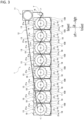
- FIG. 3 depicts a plan view of the traversing device 1.
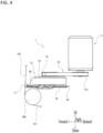
- FIG. 4 depicts a side view of the traversing device 1.
- the traversing device 1 is arranged in the thread winder 100 so as to be further arranged to the vertically-movable frame 107 of the thread winder 100.
- the traversing device 1 includes a plurality of the traversing units 13 configured to traverse the thread 101 to be wound into the package 102.
- the plurality of traversing units 13 are arranged in series in a left-and-right direction.
- the traversing device 1 also includes a drive motor 11 and a toothed transmission belt 12.
- the plurality of traversing units 13, the drive motor 11, and the toothed transmission belt 12 are incorporated into the vertically-movable frame 107. Further, the plurality of traversing units 13 and the drive motor 11 are supported by the vertically-movable frame 107 inside the vertically-movable frame 107.
- the drive motor 11 is arranged as an electric motor serving as a drive source configured to generate drive force for driving the plurality of traversing units 13.
- the toothed transmission belt 12 is to be driven by the drive motor 11 as a force transmission belt for transmitting drive force to the plurality of traversing units 13 in synchronization with one another.
- the toothed transmission belt 12 serving as an endless force transmission belt caused to rotate by the drive motor 11 has teeth formed on both an inner peripheral surface thereof and an outer peripheral surface thereof. It is to be noted that the teeth of the toothed transmission belt 12 are not shown in any drawings.
- the drive motor 11 has a drive pulley 11a fixed to an end portion of an output shaft thereof.
- Each of the plurality of traversing units 13 includes a driven pulley 15 arranged on an upper surface side thereof.
- the drive pulley 11a and the plurality of driven pulleys 15 arranged for their respective traversing units 13 are toothed pulleys having teeth formed on an outer periphery. It is to be noted that the teeth of the drive pulley 11a and the plurality of driven pulleys 15 are not shown in any drawings.
- the toothed transmission belt 12 is wound between and suspended by the drive pulley 11a and the plurality of driven pulleys 15 in such a manner that the teeth of the toothed transmission belt 12 and the teeth of the drive pulley 11a and the plurality of driven pulleys 15 are engaged to each other. It is to be noted that, in order to maintain an appropriate belt tension, the toothed transmission belt 12 is wound around an intermediate pulley 14 between the drive pulley 11a and the plurality of driven pulleys 15.
- the plurality of driven pulleys 15 arranged in their respective traversing units 13 are the pulleys the same in diameter and in number of teeth in such a manner that all the plurality of driven pulleys 15 rotate at the same speed when being driven by the toothed transmission belt 12.
- drive force is transmitted from the toothed transmission belt 12 to the plurality of driven pulleys 15 in synchronization with one another.
- drive force is transmitted from the toothed transmission belt 12 to the plurality of traversing units 13 in synchronization with one another.
- the toothed transmission belt 12 is wound around the plurality of driven pulleys 15 arranged at an upper surface side of the plurality of traversing units 13 in series along a left-and-right direction in an alternating manner between a forward side and a backward side of the belt.
- an inner peripheral side and an outer peripheral side of the toothed transmission belt 12 are alternately wound around the plurality of driven pulleys 15 in series along a left-and-right direction.
- the adjacently-arranged driven pulleys 15 in a left-and-right direction are configured to rotate in directions opposite to each other.
- one driven pulley 15 adjacently arranged to the other driven pulley 15 rotating in a clockwise direction as viewed from above rotates in a counterclockwise direction viewed from above.
- FIG. 5 depicts a bottom view of one traversing unit 13 of the plurality of traversing units 13 of the traversing device 1.
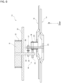
- FIG. 6 depicts a view showing schematically a configuration to transmit drive force in the traversing unit 13 of the traversing device 1.
- the plurality of traversing units 13 are arranged so as to traverse the thread 101 to be wound into the package 102, and the plurality of traversing units 13 are arranged in series in a left-and-right direction.
- Each of the plurality of traversing units 13 includes the driven pulley 15, a housing 16, a traverse guide 17, a pair of rotating blades (18, 19), a drive force transmission mechanism 20, and an interference avoidance cam 21.
- the driven pulley 15 arranged on an upper surface side of the housing 16 is a pulley to be input with drive force transmitted from the drive motor 11 to the plurality of traversing units 13 via the toothed transmission belt 12.
- the driven pulley 15 is supported rotatably with respect to the housing 16 at an upper surface side of the housing 16.
- the housing 16 houses the drive force transmission mechanism 20.
- a pair of rotating blades (18, 19) are supported rotatably with respect to the housing 16 at a lower surface side of the housing 16.
- the traversing unit 13 is shown schematically with the housing 16 being omitted.
- a cross section of the force transmission path in the drive force transmission mechanism 20 is shown in a different cross-sectional position from the middle of the path.
- FIG. 6 a cross section along a forward-and-backward direction is shown as that at a driven-pulley (15)'s side of the force transmission path in the drive force transmission mechanism 20, and a cross section along a left-and-right direction is shown as that at a pair-of-rotating-blades (18, 19)' side of the force transmission path in the drive force transmission mechanism 20.
- the traverse guide 17 is a guide member for guiding a traverse path as a path along which the thread 101 is traversed in a reciprocating manner.
- the traverse guide 17 is arranged in the housing 16.
- the thread 101 is traversed by the pair of rotating blades (18, 19) to be described later.
- the traverse guide 17 is configured to guide the traverse path as a path along which the thread 101 is traversed by the pair of rotating blades (18, 19) in a reciprocating manner. It is to be noted that, in FIGS. 3 , 5 , and 6 , the traverse path of the thread 101 guided by the traverse guide 17 is not shown.
- the traverse guide 17, as an end member of the housing 16 at a forward side, has an edge portion extending in an arc shape in a horizontal plane. More specifically, the traverse guide 17 has an edge portion, as a forward end portion of the housing 16, extending in an arc shape in a horizontal plane so as to gently curve forward in a left-and-right direction.
- the thread 101 moves in a reciprocating manner while coming into sliding contact with the edge portion of the traverse guide 17 extending in an arc shape in a horizontal plane to guide the thread 101 along the traverse path.
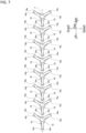
- FIG. 7 depicts a view showing the arrangement of a plurality of sets of a pair of rotating blades (18, 19) in a plurality of traversing units 13. It is to be noted that the pair of rotating blades (18, 19) shown in FIG. 7 are viewed from below, and only the pairs of rotating blades (18, 19) arranged in each of the plurality of traversing units 13 are shown schematically. As shown in FIGS. 2 to 7 , the pair of rotating blades (18, 19) are configured to rotate in directions opposite to each other so as traverse the thread 101 along the traverse guide 17 and to pass the thread 101 at both ends of the traverse path.
- the pair of rotating blades (18, 19) are arranged in each traversing unit 13 and supported rotatably around a vertical shaft at a lower side of the housing 16. Further, the pair of rotating blades (18, 19) are driven rotationally around the vertical shaft, when drive force transmitted from the driven pulleys 15 is further transmitted to the pair of rotating blades (18, 19) via the drive force transmission mechanism 20 (to be described later) housed in the housing 16, and are configured to rotate in directions opposite to each other.
- the rotating blade 18 and the rotating blade 19 are arranged in a on top of each other in the up-and-down direction. In an embodiment of the present invention, the rotating blade 18 is arranged at a lower side and the rotating blade 19 is arranged at an upper side.
- the rotating blade 18 and the rotating blade 19 are configured to rotate in directions opposite to each other as a result of being driven rotationally by the drive force transmission mechanism 20 (to be described later). As shown in FIG. 5 , e.g., the rotating blade 18 and the rotating blade 19 are configured such that, if the rotating blade 18 rotates in a clockwise direction when viewed from below, the rotating blade 19 rotates in a counterclockwise direction when viewed from below. It is to be noted that, in FIG. 5 , a clockwise direction of the rotation of the rotating blade 18 when viewed from below is denoted by an arrow X1, and a counterclockwise direction of the rotation of the rotating blade 19 when viewed from below is denoted by an arrow X2.
- the plurality of driven pulleys 15 adjacent to each other in a left-and-right direction, along which the plurality of traversing units 13 are aligned rotate in directions opposite to each other.
- the mutually adjacent rotating blades 18 of the plurality of sets of the pair of rotating blades 18, 19 in a direction, along which the plurality of traversing units 13 are aligned rotate in directions opposite to each other.
- the mutually adjacent rotating blades 19 of the plurality of sets of the pair of rotating blades 18, 19 in a direction, along which the plurality of traversing units 13 are aligned also rotate in directions opposite to each other.
- each of the rotating blade 18 and the rotating blade 19 includes three blades (18a, 18a, 18a; 19a, 19a, 19a). More specifically, the rotating blade 18 includes three blades 18a arranged at equal angle intervals in a circumferential direction so as to extend radially in a radial direction.
- the rotating blade 19 includes three blades 19a arranged at equal angle intervals in a circumferential direction so as to extend radially in a radial direction.
- the three blades 18a of the rotating blade 18 are arranged so as to extend radially along a horizontal plane.
- the three blades 19a of the rotating blade 19 are also arranged so as to extend radially along a horizontal plane.
- the rotating blades (18, 19) adjacent in an alignment direction Y are arranged along the same plane extending in parallel to a horizontal plane.
- the rotating blade 18 and the rotating blade 19 are arranged vertically side by side.
- the adjacently-arranged rotating blades 18 in the alignment direction Y rotating in directions opposite to each other are further arranged side by side in a plane parallel to a horizontal plane
- the adjacently-arranged rotating blades 19 in the alignment direction Y also rotating in directions opposite to each other are also further arranged side by side in another plane parallel to a horizontal plane.
- the rotating blades 18 adjacent to each other in the alignment direction Y rotating in directions opposite to each other in the plurality of traversing units 13 are arranged along one and the same plane extending horizontally. Further, the rotating blades 19 adjacent to each other in the alignment direction Y rotating in directions opposite to each other in the plurality of traversing units 13 are also arranged along another one and the same plane extending horizontally. It is to be noted that the alignment direction Y as a direction along which the plurality of traversing units 13 are aligned is parallel to a left-and-right direction in an embodiment of the present invention, and is indicated by the single-dotted, double-ended arrow Y in FIGS. 3 and 7 .
- the rotating blades 18 adjacent in the alignment direction Y in the plurality of traversing units 13 are arranged in proximity to each other such that the rotation paths of the adjacent rotating blades 18 overlap each other on a plane parallel to a horizontal plane.
- the rotation paths as regions through which the blades 18a of the rotating blades 18 pass are set such that the rotation paths of the rotating blades 18 adjacent in the alignment direction Y overlap each other. Since the rotation paths of the adjacent rotating blades 18 overlap each other in the alignment direction Y, one of the two adjacent rotating blades 18 crosses the rotation path of the other of the two adjacent rotating blades 18 in the alignment direction Y.
- the rotating blades 18 adjacent in the alignment direction Y are, therefore, configured to rotate in directions opposite to each other with an angle difference set such that they do not interfere with each other.
- the rotating blades 19 adjacent in the alignment direction Y in the plurality of traversing units 13 are arranged in proximity to each other such that the rotation paths of the adjacent rotating blades 19 overlap each other on a plane parallel to a horizontal plane.
- the rotation paths as regions through which the blades 19a of the rotating blades 19 pass are set such that the rotation paths of the rotating blades 19 adjacent in the alignment direction Y overlap each other.
- the rotating blades 19 adjacent in the alignment direction Y are, therefore, configured to rotate in directions opposite to each other with an angle difference set such that they do not interfere with each other.
- the rotating blade 19 rotates in a direction opposite to that of the rotating blade 18 of the same one traversing unit 13, and also rotates in a direction opposite to that of the rotating blade 19 of another traversing unit 13 adjacent in the alignment direction Y to the one traversing unit 13.
- the rotating blade 18 of the one traversing unit 13 rotates in a counterclockwise direction viewed from below and the rotating blade 19 of the one traversing unit 13 rotates in a clockwise direction when viewed from below.
- each traversing unit 13 the center of rotation of the rotating blade 18 rotating around a vertical axis, and the center of rotation of the rotating blade 19 also rotating around a vertical axis are set eccentrically to each other.
- the center of rotation of the rotating blade 18 and the center of rotation of the rotating blade 19 are set eccentrically in a left-and-right direction along the traverse path along which the thread 101 is guided by the traverse guide 17 so as to be traversed.
- the thread 101 When the thread 101 is passed from the rotating blade 18 to the rotating blade 19, the thread 101 is initially hung on a tip side of one blade 18a of the rotating blade 18 so as to be held by the one blade 18a of the rotating blade 18, and subsequently guided by the traverse guide 17 so as to move along the traverse path to one end thereof when the rotating blade 18 rotates.
- the thread 101 is caused to move to the one end of the traverse path along with the one blade 18a of the rotating blade 18 and the tip side of the one blade 18a of the rotating blade 18 holding the thread 101 is located at a position slightly inward of the traverse guide 17, the thread 101 is released from the tip side of the one blade 18a of the rotating blade 18.
- the thread 101 After the thread 101 has been passed from the rotating blade 18 to the rotating blade 19, the thread 101 is initially hung on a tip side of one blade 19a of the rotating blade 19 so as to be held by the one blade 19a of the rotating blade 19, and subsequently guided by the traverse guide 17 so as to move along the traverse path to the other end thereof when the rotating blade 19 rotates.
- the thread 101 is caused to move to the other end of the traverse path along with the one blade 19a of the rotating blade 19 and the tip side of the one blade 19a of the rotating blade 19 holding the thread 101 is located at a position slightly inward of the traverse guide 17, the thread 101 is released from the tip side of the one blade 19a of the rotating blade 19.
- the pair of rotating blades (18, 19) is configured to rotate in directions opposite to each other so as to traverse the thread 101 along the traverse guide 17 and to pass the thread 101 at both ends of the traverse path.
- a drive force transmission mechanism 20 is a mechanism for transmitting, to the rotating blades (18, 19), drive force transmitted from the toothed transmission belt 12 to the driven pulley 15.
- a first drive force transmission shaft 22, a second drive force transmission shaft 23, and a third drive force transmission shaft 24 are arranged as drive force transmission shafts to be driven by drive force transmitted from the toothed transmission belt 12 and to transmit drive force to the rotating blades (18, 19).
- the first drive force transmission shaft 22 is a solid rotor shaft rotatable around an axis in a vertical direction.
- the driven pulley 15 is fixed at an upper end side of the first drive force transmission shaft 22.
- the first drive force transmission shaft 22 also rotates along with the driven pulley 15.
- gears 25, 26 are arranged side by side in an up-and-down direction at a lower half of the first drive force transmission shaft 22. Both the gear 25 and the gear 26 are fixed to the first drive force transmission shaft 22 such that the gear 25 is positioned at an upper side and the gear 26 is positioned at a lower side.
- the gear 25 is a gear for transmitting drive force toward a rotating-blade (18)'s side
- the gear 26 is a gear for transmitting drive force toward a rotating-blade (19)'s side.
- the second drive force transmitting shaft 23 is a solid rotor shaft rotatable around an axis center in a vertical direction.
- the rotating blade 18 is fixed at a lower end side of the second drive force transmitting shaft 23.
- a gear 27 is arranged at an upper end side of the second drive force transmission shaft 23.
- the gear 27 is fixed to the second drive force transmission shaft 23.
- the gear 27 is configured such that it receives drive force transmitted from the gear 25 arranged on the first drive force transmission shaft 22 via an intermediate gear 28.
- the gear 25 at a first-drive-force-transmission-shaft (22)'s side is engaged to the intermediate gear 28, and then the intermediate gear 28 is engaged to the gear 27 at a second-drive-force-transmission-shaft (23)'s side.
- the intermediate gear 28 engaged to the gear 25 rotates in a direction opposite to that of the gear 25.
- the gear 27 engaged to the intermediate gear 28 rotates in a direction opposite to that of the intermediate gear 28 along with the second drive force transmission shaft 23.
- the gear 25 and the gear 27, therefore, rotate in the same direction, and the first drive force transmission shaft 22 and the second drive force transmission shaft 23 rotate in the same direction.
- the rotating blade 18 rotates along with the second drive force transmission shaft 23. According to such a configuration, the rotating blade 18 rotates in the same direction as the driven pulley 15.
- the third drive force transmission shaft 24 is a cylindrical hollow shaft rotatable around an axis in a vertical direction.
- the rotating blade 19 is fixed at a lower end side of the third drive force transmission shaft 24.
- the rotating blade 19 is fixed at an outer periphery of a lower end side of the third drive force transmission shaft 24 as a cylindrical hollow shaft.
- the second drive force transmission shaft 23 is arranged inside the cylindrical third drive force transmission shaft 24 so as to extend through the third drive force transmission shaft 24. It is to be noted that a center of the rotation of the second drive force transmission shaft 23, as a center of the rotation of the rotating blade 18, and a center of the rotation of the cylindrical third drive force transmission shaft 24, as a center of the rotation of the rotating blade 19, are set eccentrically to each other.
- a gear 29 is arranged at an upper end side of the third drive force transmission shaft 24.
- the gear 29 is fixed at an outer periphery of an upper end side of the cylindrical third drive force transmission shaft 24.
- the gear 29 is configured such that it is engaged to the gear 26 arranged on the first drive force transmission shaft 22 thereby to transmit drive force from the gear 26.
- the gear 29 engaged to the gear 26 rotates in a direction opposite to that of the gear 26 along with the third drive force transmission shaft 24.
- the first drive force transmission shaft 22 and the third drive force transmission shaft 24 therefore, rotate in directions opposite to each other.
- the rotating blade 19 rotates along with the third drive force transmission shaft 24. According to such a configuration, the rotating blade 19 rotates in a direction opposite to that of the driven pulley 15.
- the first drive force transmission shaft 22, the second drive force transmission shaft 23, and the third drive force transmission shaft 24 are arranged as drive force transmission shafts so as to be driven by drive force transmitted from the toothed transmission belt 12 and to transmit drive force to the rotating blades (18, 19). Further, with respect to the first drive force transmission shaft 22 rotating along with the driven pulley 15 driven rotationally by the toothed transmission belt 12, the second drive force transmission shaft 23 rotatable along with the rotating blade 18 rotates in the same direction, and the third drive force transmission shaft 24 rotatable along with the rotating blade 19 rotates in the opposite direction.
- the rotating blade 18 and the rotating blade 19 are, therefore, configured to rotate in directions opposite to each other.
- the number of teeth of each of the gear 25 and the gear 27 and the number of teeth of each of the gear 26 and the gear 29 are set such that the rotating blade 18 and the rotating blade 19 rotatable in directions opposite to each other can rotate in such directions, respectively, at the same rotation speed.
- the interference avoidance cam 21 is arranged in each of the plurality of traversing units 13 as a member for avoiding interference between the adjacently-arranged sets of the pair of rotating blades (18, 19), which sets are adjacent mutually in the alignment direction Y along which the plurality of traversing units 13 are aligned. More specifically, the interference avoidance cam 21 is arranged as a member for avoiding interference between the adjacently-arranged rotating blades 18 in the alignment direction Y as well as for avoiding interference between the adjacently-arranged rotating blades 19 in the alignment direction Y.
- the interference avoidance cam 21 formed in a disk shape is arranged on a drive force transmission shaft to be driven by drive force transmitted from the toothed transmission belt 12 and to transmit drive force to the rotating blades (18, 19).
- the interference avoidance cam 21 is arranged on the first drive force transmission shaft 22 as a drive force transmission shaft.
- the interference avoidance cam 21 is fixed to the first drive force transmission shaft 22 at a position between a lower end side of the driven pulley 15 and an upper surface side of the housing 16. Further, the interference avoidance cam 21 is fixed to the first drive force transmission shaft 22 in a state where a radial center position of the disk shape of the interference avoidance cam 21 coincides with a rotational center position of the rotation of the first drive force transmission shaft 22.
- the interference avoidance cam 21 since the interference avoidance cam 21 is arranged on the first drive force transmission shaft 22 fixed to the driven pulley 15, the interference avoidance cam 21 rotates along with the driven pulley 15. As the driven pulleys 15 adjacent mutually in the alignment direction Y rotate in directions opposite to each other, the interference avoidance cams 21 adjacent mutually in the alignment direction Y also rotate in directions opposite to each other.
- the interference avoidance cam 21 may be arranged on the second drive force transmission shaft 23 or the third drive force transmission shaft 24 instead of on the first drive force transmission shaft 22.
- the interference avoidance cam 21 is arranged on the second drive force transmission shaft 23, e.g., the second drive force transmission shaft 23 is arranged so as to extend through the rotating blade 18 and to protrude below the rotating blade 18. Then, the interference avoidance cam 21 is attached to a lower end of the second drive force transmission shaft 23.
- the interference avoidance cam 21 is arranged on the third drive force transmission shaft 24, e.g., the interference avoidance cam 21 is attached to the third drive force transmission shaft 24 between a lower end of the first drive force transmission shaft 22 and an upper surface of the rotating blade 19.
- each interference avoidance cam 21 adjacent mutually in the alignment direction Y are arranged along the same plane extending parallel to a horizontal plane.
- Each interference avoidance cam 21 includes a plurality of protrusions 21a protruding radially in a radial direction from the first drive force transmission shaft 22 as a center.
- the plurality of protrusions 21a are arranged on an outer periphery of each interference avoidance cam 21 at equal angle intervals in a circumferential direction.
- the interference avoidance cams 21 adjacent mutually in the alignment direction Y of the plurality of traversing units 13 are arranged in proximity to each other such that rotation paths of mutually adjacent sets of protrusions 21a overlap partially on a plane parallel to a horizontal plane.
- the rotation paths of the protrusions 21a, as areas through which the protrusions 21a of the interference avoidance cams 21 pass, are set such that the rotation paths of the interference avoidance cams 21 adjacent mutually in the alignment direction Y partially overlap each other.
- the protrusions 21a of the interference avoidance cams 21 adjacent mutually in the alignment direction Y overlap, the protrusions 21a of one interference avoidance cam 21 of two adjacent interference avoidance cams 21 in the alignment direction Y intrudes on the rotation path of the protrusions 21a of the other interference avoidance cam 21 of two adjacent interference avoidance cams 21.
- the interference avoidance cams 21 adjacent mutually in the alignment direction Y are, therefore, configured to rotate in directions opposite to each other with an angle difference set such that the protrusions 21a do not interfere with each other.
- the interference avoidance cams 21 are configured such that the interference avoidance cams 21 adjacent mutually in the alignment direction Y rotate in directions opposite to each other with an angle difference set such that no interference occurs. According to such a configuration, the interference avoidance cams 21 adjacent mutually in the alignment direction Y in the plurality of traversing units 13 are configured to rotate along with the first drive force transmission shafts 22 without abutting each other when the first drive force transmission shafts 22 adjacent mutually in the alignment direction Y rotate at the same speed.
- the interference avoidance cams 21 adjacent mutually in the alignment direction Y rotate in directions opposite to each other are configured to rotate along with the first drive force transmission shafts 22 without abutting each other when the first drive force transmission shafts 22 adjacent mutually in the alignment direction Y rotate in directions opposite to each other at the same rotation speed (magnitude of rotation speed).
- each interference avoidance cam 21 is configured such that the rotation paths of the protrusions 21a overlap partially between the mutually-adjacent interference avoidance cams 21 in the alignment direction Y.
- the interference avoidance cams 21 adjacent mutually in the alignment direction Y in the plurality of traversing units 13 are configured such that, when a deviation occurs in rotation speeds between the mutually-adjacent first drive force transmission shafts 22 in the alignment direction Y, the protrusions 21a thereof abut each other so as to regulate the deviation in rotation speeds between the mutually-adjacent first drive force transmission shafts 22.
- each interference avoidance cam 21 is configured to avoid interference between the adjacently-arranged sets of the pair of rotating blades (18, 19) in the alignment direction Y since the protrusions 21a abut each other so as to regulate the deviation in rotation speeds between the mutually-adjacent first drive force transmission shafts 22.
- each interference avoidance cam 21 is configured to, when a deviation occurs in rotation speeds between the mutually-adjacent first drive force transmission shafts 22 in the alignment direction Y, regulate the deviation in rotation speeds of the first drive force transmission shafts 22 so as to avoid interference between the adjacent rotating blades 18 in the alignment direction Y as well as to avoid interference between the adjacent rotating blades 19 in the alignment direction Y by way of allowing the protrusions 21a to abut each other.
- the interference avoidance cams 21 adjacent in the alignment direction Y do not abut each other.
- the toothed transmission belt 12 can transmit drive force to the plurality of traversing units 13 in synchronization with one another thereby to eliminate the need of any gear mechanisms for transmitting drive force among the plurality of traversing units 13.
- a highly-accurate traverse control of rotating the mutually-adjacent sets of the pair of rotating blades (18, 19) in directions opposite to each other so as to traverse the thread 101 can be performed without any problem of backlash occurring in a configuration using worm gears to transmit drive force among the plurality of sets of the pair of traversing units 13. Further, a noise can be suppressed because no backlash occurs in a configuration using worm gears to transmit drive force among the plurality of traversing units 13.
- the first drive force transmission shafts 22 rotate without any interference avoidance cams 21 arranged on the mutually-adjacent first drive force transmission shafts 22 abutting each other, and a normal operating state where the mutually-adjacent sets of the pair of rotating blades (18, 19) rotate in synchronization with each other is maintained.
- the toothed transmission belt 12 is damaged in the traversing device 1, a deviation occurs in rotation speeds between the first drive force transmission shafts 22 adjacent in the alignment direction Y of the plurality of traversing units 13.
- the interference avoidance cams 21 arranged on the mutually-adjacent first drive force transmission shafts 22 abut each other so as to regulate the deviation in rotation speeds between the mutually-adjacent first drive force transmission shafts 22 and to avoid interference between the mutually-adjacent sets of the pair of rotating blades (18, 19).
- a highly-accurate traverse control can be performed and a noise can be suppressed.
- interference between the mutually-adjacent sets of the pair of rotating blades (18, 19) in a direction along which the plurality of traversing units 13 are aligned can be suitably prevented thereby capable of preventing the traversing device 1 from being damaged.
- the plurality of protrusions 21a protruding radially in a radial direction of each first drive force transmission shaft 22 are arranged on each interference avoidance cam 21, and when a deviation occurs in rotation speeds between the mutually-adjacent first drive force transmission shafts 22, the adjacent sets of the protrusions 21a abut each other so as to regulate the deviation in rotation speeds between the mutually-adjacent first drive force transmission shafts 22.
- the interference avoidance cam 21 can, therefore, be configured such that a structure thereof for regulating the deviation in rotation speeds between the mutually-adjacent first drive force transmission shafts 22 is made in a space-saving manner along a circumferential direction of each first drive force transmission shaft 22. As a result, the interference avoidance cam 21 can be made compact with such a simpler structure.
- the protrusions 21a for regulating the deviation in rotation speeds between the mutually-adjacent first drive force transmission shafts 22 are arranged at equal angle intervals in a circumferential direction of each interference avoidance cam 21. According to such a configuration, an amount of deviation in rotation speeds regulated for the mutually-adjacent first drive force transmission shafts 22 can be controlled accurately.
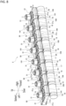
- FIG. 8 is a perspective view of a traversing device 2 according to a second embodiment of the present invention.
- FIG. 9 is a plan view of the traversing device 2.
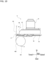
- FIG. 10 is a side view of the traversing device 2.
- FIG. 11 is a view showing schematically a configuration transmitting drive force in a traversing unit 30 of the traversing device 2.
- FIG. 12 is a block diagram showing schematically a control configuration of the traversing device 2.
- the traversing device 2 arranged in the thread winder 100 is mounted on the vertically-movable frame 107 of the thread winder 100.
- the traversing device 2 includes a plurality of traversing units 30 configured to traverse the thread 101 to be wound as the package 102, and the plurality of traversing units 30 are arranged in series along a left-and-right direction.
- the traversing device 2 also includes a control unit 32 configured to control a drive motor 31 arranged in each of the plurality of traversing units 30.
- the traversing device 2 of the second embodiment is configured such that the pair of rotating blades (18, 19) of each traversing unit 30 are driven by the drive motor 31 arranged in each traversing unit 30.
- the traversing device 2 is not arranged with one drive motor 11 serving as a drive source and a toothed transmission belt 12 for transmitting drive force from the one drive motor 11.
- a plurality of sets of the pair of rotating blades (18, 19) are driven by drive force generated by a plurality of drive motors 31 arranged in a plurality of traversing units 30, respectively.
- each of the plurality of traversing units 30 in the traversing device 2 includes the drive motor 31, a housing 16, a traverse guide 17 arranged in the housing 16, a pair of rotating blades (18, 19), a drive force transmission mechanism 20, and an interference avoidance cam 21.
- the housing 16, the traverse guide 17, the pair of rotating blades (18, 19), the drive force transmission mechanism 20, and the interference avoidance cam 21 in the traversing unit 30 are configured in the same manner as the housing 16, the traverse guide 17, the pair of rotating blades (18, 19), the drive force transmission mechanism 20, and the interference avoidance cam 21 in the traversing unit 13 of the first embodiment.
- the traversing unit 30 of the second embodiment differs from the traversing unit 13 of the first embodiment in that the driven pulley 15 is not arranged but the drive motor 31 is arranged.
- the drive motor 31 as an electric motor is arranged in each traversing unit 30.
- the drive motor 31 is, e.g., a synchronous motor.
- the drive motor 31 is a drive source configured to generate drive force for rotating the pair of rotating blades (18, 19) in directions opposite to each other in each traversing unit 30.
- the drive motor 31 is arranged above the housing 16 so as to generate a rotational drive force around a vertical axis.
- an output shaft (not shown) of the drive motor 31 is connected to the first drive force transmission shaft 22 in the drive force transmission mechanism 20, and the rotation of the drive motor 31 is to be directly input to the first drive force transmission shaft 22.
- a lower end of the output shaft of the drive motor 31 and an upper end of the first drive force transmission shaft 22 are coupled to each other such that the first drive force transmission shaft 22 can rotate with the rotation of the drive motor 31.
- the output shaft of the drive motor 31 and the first drive force transmission shaft 22 are not limited to being directly connected, and there may be adopted a configuration that drive force is transmitted via the engagement between a gear arranged on the output shaft of the drive motor 31 and a gear arranged on the first drive force transmission shaft 22.
- the first drive force transmission shaft 22 driven by the drive motor 31 rotates.
- Drive force is transmitted from the rotating first drive force transmission shaft 22 to the second drive force transmission shaft 23 via the engagement to the gear 25, the intermediate gear 28, and the gear 27 so that the second drive force transmission shaft 23 rotates in the same direction as that of the first drive force transmission shaft 22.
- the rotating blade 18 rotates along with the second drive force transmission shaft 23 in the same direction as that of the first drive force transmission shaft 22.
- drive force is transmitted from the rotating first drive force transmission shaft 22 to the third drive force transmission shaft 24 via the engagement to the gear 26 and the gear 27 so that the third drive force transmission shaft 24 rotates in a direction opposite to that of the first drive force transmission shaft 22.
- the rotating blade 19 rotates along with the third drive force transmission shaft 24 in a direction opposite to that of the first drive force transmission shaft 22.
- the rotating blade 18 rotates in the same direction and the rotating blade 19 rotates in an opposite direction with respect to the first drive force transmission shaft 22 driven by the drive motor 31.
- the rotating blade 18 and the rotating blade 19 rotate in directions opposite to each other.
- the drive motor 31 is arranged in each of the plurality of traversing units 30 such that the rotation of the drive motor 31 is controlled by the control unit 32.
- the traversing device 2 is arranged with the control unit 32 such that the rotation of the plurality of drive motors 31 in the plurality of traversing units 30 is all controlled by the control unit 32.
- the control unit 32 includes, e.g., a central processing unit (CPU), a read-only memory (ROM), and a random access memory (RAM).
- the CPU reads out a program corresponding to processing contents from the ROM, deploys the program to the RAM, and controls centrally the operation of each of the plurality of drive motors 31 in cooperation with the deployed program.
- the control unit 32 is configured to control the plurality of drive motors 31 arranged in the plurality of traversing units 30 so as to rotate at the same rotation speed. Further, the control unit 32 is configured to control the drive motors 31 adjacent mutually in the alignment direction Y so as to rotate in directions opposite to each other. As a result, the drive motors 31 of the traversing units 30 adjacent mutually in the alignment direction Y rotate at the same rotation speed in directions opposite to each other in accordance with the control by the control unit 32.
- the drive motor 31 of one of the plurality of traversing units 30 rotates in a clockwise direction, e.g., when viewed from above, therefore, the drive motor 31 adjacent to the drive motor 31 in the other of the plurality of traversing units in the alignment direction Y rotates in a counterclockwise direction when viewed from above. Still further, the drive motors 31 rotating clockwise when viewed from above and the drive motors 31 rotating counterclockwise when viewed from above, which are all adjacent mutually in the alignment direction Y, rotate at the same speed as each other.
- the first drive force transmission shafts 22 adjacent mutually in the alignment direction Y also rotate at the same rotation speed in directions opposite to each other, as in the first embodiment.
- the interference avoidance cams 21 arranged on the first drive force transmission shafts 22 also rotate in the same manner as in the first embodiment. In other words, since the mutually adjacent first drive force transmission shafts 22 rotate at the same rotation speed in directions opposite to each other, the interference avoidance cams 21 adjacent mutually in the alignment direction Y also rotate at the same rotation speed in directions opposite to each other.
- the interference avoidance cam 21 of one of the plurality of traversing units 30 rotates in a clockwise direction, e.g., when viewed from above, therefore, the interference avoidance cam 21 adjacent to the interference avoidance cam 21 of the other of the plurality of traversing units 30 in the alignment direction Y rotates in a counterclockwise direction when viewed from above. Further, the interference avoidance cams 21 rotating clockwise when viewed from above and the interference avoidance cams 21 rotating counterclockwise when viewed from above, which are all adjacent mutually in the alignment direction Y, rotate at the same speed as each other. It is to be noted that, in FIG.
- a direction of the rotation of the interference avoidance cams 21 rotatable in a clockwise direction when viewed from above is indicated by an arrow R1
- a direction of rotation of the interference avoidance cams 21 rotatable in a counterclockwise direction when viewed from above is indicated by an arrow R2.
- the interference avoidance cam 21 arranged in each of the plurality of traversing units 30 has the same configuration as the interference avoidance cam 21 arranged in each of the plurality of traversing units 13 in the first embodiment. That is, the mutually-adjacent interference avoidance cams 21 of the plurality of traversing units 30 are configured to rotate in directions opposite to each other with an angle difference set such that the mutually-adjacent interference avoidance cams 21 do not interfere with each other in the alignment direction Y.
- the interference avoidance cams 21 adjacent mutually in the alignment direction Y in the plurality of traversing units 30 rotate along with the first drive force transmission shafts 22 without abutting each other.
- the interference avoidance cams 21 of the plurality of traversing units 30 are configured such that the rotation paths of the mutually-adjacent sets of protrusions 21a of the interference avoidance cams 21 adjacent mutually in the alignment direction Y partially overlap.
- the interference avoidance cams 21 adjacent mutually in the alignment direction Y of the plurality of traversing units 30 are, therefore, configured such that, when rotation speeds of the first drive force transmission shafts 22 adjacent mutually in the alignment direction Y deviate from each other, the mutually-adjacent sets of protrusions 21a of the interference avoidance cams 21 adjacent mutually in the alignment direction Y abut each other thereby to regulate the deviation in rotation speed between the first drive force transmission shafts 22.
- interference avoidance cams 21 are configured to avoid interference between the mutually-adjacent sets of the pair of rotating blades (18, 19) in the alignment direction Y by way of mutually-adjacent sets of the protrusions 21a abutting each other so as to regulate the deviation in rotation speeds between the first drive force transmission shafts 22.
- the interference avoidance cams 21 adjacent mutually in the alignment direction Y do not abut each other. In a normal operating state of the traversing device 2, therefore, the interference avoidance cams 21 do not abut each other. If the drive motor 31 in any of the plurality of traversing units 30 fails, however, rotation speeds of the first drive force transmission shafts 22 adjacent mutually in the alignment direction Y deviate from each other. In such a case, the interference avoidance cams 21 adjacent mutually in the alignment direction Y abut each other so as to regulate the deviation in rotation speeds between the first drive force transmission shafts 22 adjacent mutually in the alignment direction Y.
- the interference avoidance cam 21 is arranged on the first drive force transmission shaft 22 in each of the plurality of traversing units 30, e.g., but no limitation is intended.
- the interference avoidance cam 21 of each of the plurality of traversing unit 30 may be arranged on the second drive force transmission shaft 23 or the third drive force transmission shaft 24 instead of on the first drive force transmission shaft 22.
- the interference avoidance cam 21 is arranged on the second drive force transmission shaft 23, e.g., the second drive force transmission shaft 23 is arranged so as to extend through the rotating blade 18 and to protrude below the rotating blade 18. Then, the interference avoidance cam 21 is attached to a lower end of the second drive force transmission shaft 23.
- the interference avoidance cam 21 is arranged on the third drive force transmission shaft 24, e.g., the interference avoidance cam 21 is attached to the third drive force transmission shaft 24 between a lower end of the first drive force transmission shaft 22 and an upper surface of the rotating blade 19.
- the pair of rotating blades (18, 19) of each of the plurality of traversing units 30 are rotationally driven via the first to third drive force transmission shafts (22, 23, 24) by the drive motor 31 arranged individually in each traversing unit 30.
- This avoids the need of any gear mechanisms for transmitting drive force among the plurality of traversing units 30.
- a highly-accurate traverse control can be made such that the mutually-adjacent sets of the pair of rotating blades (18, 19) rotate in directions opposite to each other so as to traverse the thread 101 without any problem of backlash occurring in a configuration using worm gears to transmit drive force between the plurality of traversing units 13.
- a noise can be suppressed because there is no problem of backlash occurring in a configuration using worm gears so as to transmit drive force between the plurality of traversing units 13. Still further, since the drive motors 31 of the plurality of traversing units 30 are controlled by the control unit 32 so as to rotate at the same rotation speed, a state where the mutually-adjacent sets of the pair of rotating blades (18, 19) of the plurality of traversing units 30 rotate in synchronization with each other can be maintained.
- the first drive force transmission shafts 22 rotate without any interference avoidance cams 21 arranged on the mutually-adjacent first drive force transmission shafts 22 abutting each other, and a normal operating state where the mutually-adjacent sets of the pair of rotating blades (18, 19) rotate in synchronization with each other can be maintained.
- the traversing device 2 when the drive motor 30 in any of the plurality of traversing units 30 fails, a deviation occurs in rotation speeds between the first drive force transmission shafts 22 adjacent mutually in the alignment direction Y of the plurality of traversing units 30.
- the interference avoidance cams 21 arranged on the mutually-adjacent first drive force transmission shafts 22 abut each other so as to regulate the deviation in rotation speeds between the mutually-adjacent first drive force transmission shafts 22, and the mutually-adjacent sets of the pair of rotating blades (18, 19) are prevented from interfering with each other.
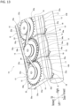
- FIG. 13 is a perspective view of a traversing device 1A, according to a modified embodiment, showing a portion thereof.
- FIG. 14 is a plan view of the traversing device 1A showing a portion thereof.
- the traversing device 1A according to a modified embodiment shown in FIGS. 13 and 14 is configured in the same manner as the traversing device 1 of the first embodiment but differs from the traversing device 1 of the first embodiment in that interference avoidance cams (33, 34) different mutually in shape are arranged alternately in the plurality of traversing units 13 adjacent mutually in the alignment direction Y.
- interference avoidance cams (33, 34) having different shapes are arranged alternately in the plurality of traversing units 13 adjacent mutually in the alignment direction Y.
- the traversing unit 13 arranged with the interference avoidance cam 33 and the traversing unit 13 arranged with the interference avoidance cam 34 different in shape from the interference avoidance cam 33 are alternately aligned in the alignment direction Y.
- the interference avoidance cam 33 and the interference avoidance cam 34 different in shape from each other are alternately arranged side by side in the alignment direction Y.
- a plurality of protrusions 33a protruding radially in a radial direction are arranged at equal angle intervals in a circumferential direction of the interference avoidance cam 33 on an outer periphery of the interference avoidance cam 33 in a disk shape.
- a groove recessed and curved in a U-shape is formed between the protrusions 33a arranged at equal angle intervals in a circumferential direction on an outer periphery of the interference avoidance cam 33 so as to protrude radially in a radial direction.
- a groove recessed and curved in a U-shape is formed between the protrusions 33a adjacent in a circumferential direction on an outer periphery of the interference avoidance cam 33.
- the interference avoidance cam 34 is arranged in the traversing unit 13 adjacent to the traversing unit 13 arranged with the interference avoidance cam 33 in the alignment direction Y.
- the interference avoidance cam 34 is different in shape from the interference avoidance cam 33.
- a plurality of protrusions 34a each protruding in a short cylindrical shape upward in a circumferential direction of the interference avoidance cam 34 are arranged in an area at or in proximity to an outer peripheral edge portion on an upper surface of the interference avoidance cam 34 in a disk shape.
- the plurality of protrusions 34a each protruding in a cylindrical shape upward at or in proximity to an outer circumferential edge portion on an upper surface of the interference avoidance cam 34 in a disk shape are arranged at equal angle intervals in a circumferential direction on an upper surface of the interference avoidance cam 34.
- the interference avoidance cam 33 and the interference avoidance cam 34 are arranged next to each other.
- the interference avoidance cam 33 and the interference avoidance cam 34 are arranged in proximity to each other such that the rotation paths of the protrusions 33a of the interference avoidance cam 33 and the rotation paths of the protrusions 34a of the interference avoidance cam 34 overlap partially in a plane parallel to a horizontal plane.
- the rotation path of the protrusion 33a as an area through which the protrusion 33a of the interference avoidance cam 33 passes
- the rotation path of the protrusion 34a as an area through which the protrusion 34a of the interference avoidance cam 34 adjacent to the interference avoidance cam 33 in the alignment direction Y passes
- the protrusion 34a of the interference avoidance cam 34 crosses the rotation path of the protrusion 33a of the interference avoidance cam 33.
- the interference avoidance cam 33 and the interference avoidance cam 34 adjacent in the alignment direction Y therefore, rotate in directions opposite to each other with an angle difference set such that the protrusion 33a and the protrusion 34a do not interfere with each other.
- the protrusion 34a of the interference avoidance cam 34 crosses the rotation path of the protrusion 33a of the interference avoidance cam 33, the protrusion 34a enters the U-shaped groove between the circumferentially-aligned protrusions 33a of the interference avoidance cam 33 without interfering with the protrusion 33a.
- the interference avoidance cams (33, 34) are configured to rotate in directions opposite to each other with an angle difference set such that the interference avoidance cam 33 and the interference avoidance cam 34 adjacent in the alignment direction Y do not interfere with each other. According to such a configuration, when rotation speeds of the first drive force transmission shafts 22 adjacent in the alignment direction Y are the same, the interference avoidance cam 33 and the interference avoidance cam 34 adjacent in the alignment direction Y in the plurality of traversing units 13 rotate along with the first drive force transmission shaft 22 without abutting each other.
- the interference avoidance cam 33 and the interference avoidance cam 34 adjacent in the alignment direction Y rotatable in directions opposite to each other rotate along with the first drive force transmission shafts 22 without abutting each other when the first drive force transmission shafts 22 adjacent mutually in the alignment direction Y rotatable in directions opposite to each other rotate at the same rotation speed.
- the interference avoidance cams (33, 34) are configured such that the rotation path of the protrusion 33a of the interference avoidance cam 33 and the rotation path of the protrusion 34a of the interference avoidance cam 34 adjacent to the interference avoidance cam 33 in the alignment direction Y overlap partially.
- the interference avoidance cam 33 and the interference avoidance cam 34 adjacent in the alignment direction Y in the plurality of traversing units 13 are configured such that the protrusion 33a of the interference avoidance cam 33 and the protrusion 34a of the interference avoidance cam 34 adjacent to the interference avoidance cam 33 in the alignment direction Y abut so as to regulate the deviation in rotation speeds between the first drive force transmission shafts 22.
- the interference avoidance cams (33, 34) are configured to avoid interference between the mutually-adjacent sets of the pair rotating blades (18, 19) in the alignment direction Y by way of the protrusion 33a of the interference avoidance cam 33 and the protrusion 34a of the interference avoidance cam 34 coming abutting each other so as to regulate the deviation in rotation speeds between the first drive force transmission shafts 22.
- the interference avoidance cams (33, 34) are configured to, when a deviation occurs in rotation speeds between the first drive force transmission shafts 22 adjacent mutually in the alignment direction Y, regulate the deviation in rotation speed between the mutually-adjacent first drive force transmission shafts 22 and avoid interference between the rotating blades 18 adjacent mutually in the alignment direction Y and avoid interference between the rotating blades 19 adjacent mutually in the alignment direction Y by way of the protrusion 33a of the interference avoidance cam 33 and the protrusion 34a of the interference avoidance cam 34 abutting each other.
- the interference avoidance cam 33 and the interference avoidance cam 34 adjacent in the alignment direction Y do not abut each other. In a normal operating state of the traversing device 1A, therefore, the interference avoidance cam 33 and the interference avoidance cam 34 do not abut each other. If the toothed transmission belt 12 is damaged, however, a deviation occurs in rotation speeds between the first drive force transmission shafts 22 adjacent mutually in the alignment direction Y. In such a case, the interference avoidance cam 33 and the interference avoidance cam 34 adjacent in the alignment direction Y abut each other so as to regulate the deviation in rotation speeds between the first drive force transmission shafts 22 adjacent in the alignment direction Y.
- the deviation in rotation speed between the rotating blades 18 adjacent mutually in the alignment direction Y is also restricted.
- the deviation in rotation speed between the rotating blades 19 adjacent mutually in the alignment direction Y is also restricted. Interference between the rotating blades 18 adjacent mutually in the alignment direction Y can, therefore, be avoided, and interference between the rotating blades 19 adjacent mutually in the alignment direction Y can also be avoided.
- the mutually-adjacent rotating blades (18, 19) each includes three blades (18a, 19a) so as to extend radially in a radial direction but no limitation is intended.
- the number of blades extending radially in a radial direction in each of the rotating blades is not limited to three and, e.g., a rotating blade including two or four blades may be adopted as such a rotating blade.
Landscapes
- Engineering & Computer Science (AREA)
- Quality & Reliability (AREA)
- Textile Engineering (AREA)
- Winding Filamentary Materials (AREA)
- Guides For Winding Or Rewinding, Or Guides For Filamentary Materials (AREA)
- Spinning Methods And Devices For Manufacturing Artificial Fibers (AREA)
Abstract
Description
- The present invention relates to a traversing device including a plurality of traversing units arranged in an alignment direction each configured to traverse a thread to be wound into a package.
- The traversing device disclosed in Patent Document 1 including a plurality of traversing units arranged in an alignment direction each configured to traverse a thread to be wound into a package has been known. The traversing device disclosed in Patent Document 1 includes a plurality of traversing units (traversing apparatuses 2) arranged in an alignment direction. Each of the plurality of traversing units includes a traverse guide (guide plate 9) and a pair of rotating blades (blades 7, 8). The traverse guide guides a traverse path along which the thread is traversed, and the pair of rotating blades rotate in directions opposite to each other so as to traverse the thread along the traverse guide and to pass the thread between both ends of the traverse path.
- In the traversing device disclosed in Patent Document 1, drive force is transmitted to each of the plurality of traversing units by a worm gear or a toothed transmission belt. More specifically, as a configuration using a worm gear, Patent Document 1 describes an embodiment driving rotationally
rotors worms worm wheels rotors rotors rotors rotors rotors rotors rotors - In the traversing device disclosed in Patent Document 1, in both of the configuration using worm gears and the configuration using a toothed transmission belt, the rotating blades (blades 7, 8) in the plurality of traversing units rotate in synchronization with each other. In the traversing device disclosed in Patent Document 1, therefore, the rotating blades arranged adjacent to each other in the alignment direction of the plurality of traversing units can be prevented from interfering with each other, even when being arranged closer to each other. In other words, even when the rotating blades are arranged closer to each other so that paths of rotation of the rotating blades adjacent in the alignment direction overlap partially, the rotating blades adjacent in the alignment direction can be prevented from interfering with each other.
- Patent Document 1:
Japanese Examined Patent Application Publication No. H03-72544 - In the traversing device disclosed in Patent Document 1, in the configuration using a worm gear, since the worm and worm wheel are always engaged to each other, a state where the rotating blades of the plurality of traversing units rotate in synchronization with each other is constantly maintained. The rotating blades adjacent in the alignment direction in the plurality of traversing units can, therefore, be prevented from interfering with each other and thereby, the plurality of traversing units can be prevented from being damaged. Problems arise, however, due to the structure of the worm gear, it is difficult to eliminate backlash between the worm and worm wheel, and it is difficult to perform an accurate traverse control such that the pair of rotating blades to rotate in directions opposite to each other thereby to traverse the thread. On the other hand, in the configuration using a toothed transmission belt of the traversing device disclosed in Patent Document 1, no backlash occurs between the worm and worm wheel, and precise traverse control can be performed. When using a toothed transmission belt, however, the toothed transmission belt may become damaged. When the toothed transmission belt becomes damaged, the synchronous rotation of the rotating blades in the plurality of traversing units is impaired. When the synchronous rotation of the rotating blades in the plurality of traversing units is impaired, the rotating blades adjacent in the alignment direction in the plurality of traversing units interfere with one another and as a result, the plurality of traversing units fail.
- The present invention has been made in view of the above-described technical problems, and an objective thereof is to provide a traversing device capable of performing an accurate traverse control, suitably preventing rotating blades adjacent in an alignment direction of a plurality of traversing units from interfering with each other, and avoiding device failure.
- A first aspect of the present invention is a traversing device comprising:
- a plurality of traversing units arranged in an alignment direction each configured to traverse a thread to be wound into a package;
- a drive motor; and
- a toothed transmission belt driven by the drive motor for transmitting drive force to the plurality of traversing units in synchronization with each other,
- each of the plurality of traversing units including
- a traverse guide for guiding a traverse path along which the thread is traversed in a reciprocating manner,
- a pair of rotating blades configured to rotate in directions opposite to each other so as to traverse the thread along the traverse guide, and to pass the thread between both ends of the traverse path,
- a drive force transmission shaft driven by drive force transmitted from the toothed transmission belt for transmitting drive force to the pair of rotating blades, and
- an interference avoidance cam arranged on the drive force transmission shaft configured to avoid interference between adjacently-arranged sets of the pair of rotating blades in the alignment direction of the plurality of traversing units,
- wherein a plurality of sets of the pair of rotating blades, of the plurality of traversing units, adjacent in the alignment direction are arranged in the same plane, the adjacent sets of the pair of rotating blades configured to rotate in directions opposite to each other, and
- wherein interference avoidance cams, of the plurality of traversing units, adjacent in the alignment direction are configured such that
the interference avoidance cams rotate along with drive force transmission shafts without abutting each other in a state where rotation speeds of the drive force transmission shafts adjacent in the alignment direction are the same, and, - when a deviation occurs in rotation speeds between the drive force transmission shafts adjacent in the alignment direction, the interference avoidance cams adjacent in the alignment direction abut each other so as to regulate the deviation in rotation speeds of the drive force transmission shafts thereby to avoid interference between the adjacent sets of the pair of rotating blades in the alignment direction.
- According to the above-described first aspect of the traversing device, the toothed transmission belt transmits drive force to the plurality of traversing units in synchronization with each other thereby to eliminate the need of any gear mechanisms for transmitting drive force among the plurality of traversing units. A highly-accurate traverse control can, therefore, be performed such that the pair of rotating blades of each set rotate in directions opposite to each other thereby to traverse the thread without any problem of backlash occurring in a configuration using worm gears to transmit drive force among the plurality of traversing units. Further, a noise can be suppressed because there is no problem of backlash occurring in a configuration using worm gears to transmit drive force among the plurality of traversing units. According to the above-described first aspect of the traversing device, in a normal operating state where rotation speeds of the drive force transmission shafts adjacent in the alignment direction of the plurality of traversing units are the same, the adjacent drive force transmission shafts rotate without any interference avoidance cams arranged thereon abutting each other so that the adjacently-arranged sets of the pair of rotating blades are maintained in a normal operating state of rotating in synchronization with each other. On the other hand, when the toothed transmission belt is damaged in the traversing device, a deviation occurs in rotation speeds between the drive force transmission shafts adjacent in the alignment direction of the plurality of traversing units. According to the above-described first aspect of the traversing device, however, when a deviation occurs in rotation speeds between the adjacent drive force transmission shafts, the interference avoidance cams arranged on the adjacent drive force transmission shafts abut each other so as to regulate the deviation in rotation speeds between the adjacent drive force transmission shafts thereby to avoid interference between the adjacently-arranged sets of the pair of rotating blades. According to the above-described first aspect of the traversing device, therefore, a highly accurate traverse control can be performed and a noise can be suppressed. Further, any interference between the adjacently-arranged sets of the pair of rotating blades in the alignment direction of the plurality of traversing units can be suitably prevented, thereby capable of preventing the traversing device from being damaged.
- A second aspect of the present invention is a traversing device comprising:
- a plurality of traversing units arranged in an alignment direction each configured to traverse a thread to be wound into a package,
- each of the plurality of traversing units including
- a traverse guide for guiding a traverse path along which the thread is traversed in a reciprocating manner,
- a pair of rotating blades configured rotate in directions opposite to each other so as to traverse the thread along the traverse guide, and to pass the thread between both ends of the traverse path,
- a drive motor,
- a drive force transmission shaft driven by drive force transmitted from the drive motor for transmitting drive force to the pair of rotating blades, and
- an interference avoidance cam arranged on the drive force transmission shaft configured to avoid interference between adjacently-arranged sets of the pair of rotating blades in the alignment direction of the plurality of traversing units,
- wherein a plurality of sets of the pair of rotating blades, of the plurality of traversing units, adjacent in the alignment direction are arranged in the same plane, the adjacent sets of the pair of rotating blades configured to rotate in directions opposite to each other,
- wherein interference avoidance cams, of the plurality of traversing units, adjacent in the alignment direction are configured such that
- the interference avoidance cams rotate along with drive force transmission shafts without abutting each other in a state where rotation speeds of the drive force transmission shafts adjacent in the alignment direction are the same, and,
- when a deviation occurs in rotation speeds between the drive force transmission shafts adjacent in the alignment direction, the interference avoidance cams adjacent in the alignment direction abut each other so as to regulate the deviation in rotation speeds of the drive force transmission shafts thereby to avoid interference between the adjacent sets of the pair of rotating blades in the alignment direction, and
- wherein the traversing device further comprises a control unit configured to control the drive motor arranged in each of the plurality of traversing units such that drive motors rotate at the same rotation speed.
- According to the above-described second aspect of the traversing device, the pair of rotating blades of each of the plurality of traversing units are driven rotationally via the drive force transmission shafts by the drive motor arranged individually in each of the plurality of traversing units. This eliminates the need of any gear mechanisms for transmitting drive force among the plurality of traversing units. As a result, a highly-accurate traverse control can be performed such that the pair of rotating blades of each set rotate in directions opposite to each other thereby to traverse the thread without any problem of backlash occurring in a configuration using worm gears to transmit drive force among the plurality of traversing units. Further, a noise can be suppressed because there is no problem of backlash occurring in a configuration using worm gears to transmit drive force among the plurality of traversing units. Still further, since the drive motors of the plurality of traversing units are controlled by the control unit so as to rotate at the same rotation speed, the plurality of sets of the pair of rotating blades of the plurality of traversing units are maintained in a state of rotating in synchronization with each other. According to the above-described second aspect of the traversing device, in a normal operating state where rotation speeds of the drive force transmission shafts adjacent in the alignment direction of the plurality of traversing units are the same, the drive force transmission shafts rotate without any interference avoidance cams arranged thereon abutting each other so that the adjacently-arranged sets of the pair of rotating blades are maintained in a state of rotating in synchronization with each other. On the other hand, in the traversing device, when the drive motor in any of the plurality of traversing units fails, a deviation occurs in rotation speeds between the drive force transmission shafts adjacent in the alignment direction of the plurality of traversing units. According to the above-described second aspect of the traversing device, however, when a deviation occurs in rotation speeds between the adjacent drive force transmission shafts, the interference avoidance cams arranged on the adjacent drive force transmission shafts abut each other so as to regulate a deviation in rotation speeds between the adjacent drive force transmission shafts, and the adjacently-arranged sets of the pair of rotating blades are prevented from interfering with each other. According to the above-described second aspect of the traversing device, therefore, a highly-accurate traverse control can be performed and a noise can be suppressed. Further, interference between the adjacently-arranged sets of the pair of rotating blades in the alignment direction of the plurality of traversing units can be suitably prevented, thereby capable of preventing the traversing device from being damaged.
- A third aspect of the present invention is the traversing device in the above-described first or second aspect, wherein
- each of the interference avoidance cams includes a plurality of protrusions protruding radially in a radial direction around each of the drive force transmission shafts, and,
- when a deviation occurs in rotation speeds of the drive force transmission shafts adjacent in the alignment direction, adjacently-arranged sets of the plurality of protrusions of the interference avoidance cams in the alignment direction abut each other so as to regulate the deviation in rotation speeds of the drive force transmission shafts.
- According to the above-described third aspect of the traversing device, the plurality of protrusions protruding radially in a radial direction around each of the drive force transmission shafts are arranged on each of the interference avoidance cams, and, when a deviation occurs in rotation speeds between the adjacent drive force transmission shafts, the adjacently-arranged sets of the plurality of protrusions of the interference avoidance cams in the alignment direction abut each other so as to regulate the deviation in rotation speeds between the adjacent drive force transmission shafts. As a result, structures with respect to the interference avoidance cams can be arranged, so as to regulate the deviation in rotation speeds between the adjacent drive force transmission shafts, in a space-saving manner along circumferential directions around their respective drive force transmission shafts. Each of the interference avoidance cams can, therefore, be made compact with a simpler structure.
- A fourth aspect of the present invention is the traversing device in the above-described third aspect, wherein
the plurality of protrusions are arranged on an outer periphery of each of the interference avoidance cams at equal angle intervals in a circumferential direction of each of the interference avoidance cams. - According to the above-described fourth aspect of the traversing device, the protrusions for regulating the deviation in rotation speeds between the adjacent drive force transmission shafts are arranged at equal angle intervals in a circumferential direction of each of the interference avoidance cams. With such a configuration, an amount of deviation in rotation speeds regulated for the adjacent drive force transmission shafts can be accurately controlled.
- The traversing device according to the present invention does not necessarily include all of the above-described first or second aspect along with the above-described third and fourth aspects. The traversing device according to the present invention may include, e.g., the above-described first or second aspect exclusive of the above-described third and fourth aspects. Further, the traversing device according to the present invention may include the above-described first or second aspect along with the above-described third aspect. Still further, the traversing device according to the present invention may include the above-described first or second aspect along with the above-described third and fourth aspects.
- According to the present invention, there can be provided a traversing device capable of performing an accurate traverse control, suitably preventing rotating blades adjacent in an alignment direction of a plurality of traversing units from interfering with each other, and avoiding device failure.
-
-
FIG. 1 depicts a perspective view of a configuration as a whole of a thread winder equipped with a traversing device. -
FIG. 2 depicts a perspective view of the traversing device according to a first embodiment of the present invention. -
FIG. 3 depicts a plan view of the traversing device shown inFIG. 2 . -
FIG. 4 depicts a side view of the traversing device shown inFIG. 2 . -
FIG. 5 depicts a bottom view of a traversing unit of the traversing device. -
FIG. 6 depicts a view showing schematically a configuration to transmit drive force in a traversing unit of the traversing device shown inFIG. 2 . -
FIG. 7 depicts a view showing the arrangement of a plurality of sets of a pair of rotating blades in a plurality of traversing units. -
FIG. 8 depicts a perspective view of the traversing device according to a second embodiment of the present invention. -
FIG. 9 depicts a plan view of the traversing device shown inFIG. 7 . -
FIG. 10 depicts a side view of the traversing device shown inFIG. 7 . -
FIG. 11 depicts a view showing schematically a configuration to transmit drive force in a traversing unit of the traversing device shown inFIG. 7 . -
FIG. 12 depicts a block diagram showing schematically a control configuration of the traversing device shown inFIG. 7 . -
FIG. 13 depicts a perspective view of a traversing device according to a modified example showing a portion of the traversing device. -
FIG. 14 depicts a plan view of the traversing device inFIG. 13 showing a portion of the traversing device. - Hereinafter, embodiments of the present invention will be described with reference to the drawings. The present invention can be widely applied to various uses as a traversing device including a plurality of traversing units arranged in an alignment direction each configured to traverse thread to be wound into a package.
- A traversing device according to an embodiment of the present invention is arranged in a textile machine such as a thread winder configured to wind thread spun from a spinning machine.
FIG. 1 depicts a perspective view of a configuration as a whole of athread winder 100 equipped with a traversing device. In the following descriptions, initially, thethread winder 100, e.g., will be described as a textile machine including a traversing device, and subsequently, a traversing device 1 (seeFIG. 2 ) according to a first embodiment of the present invention and a traversing device 2 (seeFIG. 8 ) according to a second embodiment of the present invention will be described. It is to be noted that, in the following descriptions, a up-and-down direction, a forward-and-backward direction, and a left-and-right direction used when referring to thethread winder 100 and the traversing device (1, 2) arranged in thethread winder 100 are to be defined by the arrows shown inFIG. 1 andFIGS. 2 to 10 to be described later. - As shown in
FIG. 1 , thethread winder 100 including the traversing device 1 or thetraversing device 2 is a textile machine configured to wind a plurality ofthreads 101 spun from a spinning machine (not shown) into a plurality ofpackages 102, respectively. Thethread winder 100 includes abase frame 103, abody frame 104 supported on thebase frame 103, a disk-shapedturret plate 105 supported by thebase frame 104, two bobbin holders (106a, 106b) supported by theturret plate 105, and a vertically-movable frame 107 supported by thebody frame 104. - The
turret plate 105 formed in a disk shape is configured to pivot around a horizontal axis with respect to thebody frame 104. The two bobbin holders (106a, 106b) have their respective end portions supported by theturret plate 105 so as to extend in a cantilever-like manner at a left side of theturret plate 105. It is to be noted that the bobbin holders (106a, 106b) are driven rotationally by a drive motor (not shown) arranged at a right side of theturret plate 105. - Two sets of a plurality of bobbins (108a, 108b) are mounted on the two bobbin holders (106a, 106b) supported by the
turret plate 105, respectively. More specifically, a plurality ofbobbins 108a are mounted on onebobbin holder 106a, and a plurality ofbobbins 108b are mounted on theother bobbin holder 106b. The plurality ofbobbins 108a are mounted, on onebobbin holder 106a extending in a cantilever-like manner, in series along a longitudinal direction of thebobbin holder 106a. The plurality ofbobbins 108b are mounted, on theother bobbin holder 106b extending in a cantilever-like manner, in series along a longitudinal direction of thebobbin holder 106b. - The
turret plate 105 is configured to rotate 180° around a horizontal axis. Thethread 101 is wound onto thebobbin 108a of thebobbin holder 106a located at an upper winding position so as to form thepackage 102. InFIG. 1 , onebobbin holder 106a is located at an upper winding position where thethread 101 is wound into thepackage 102, and theother bobbin holder 106b is located at a lower standby position. When thethread 101 is wound at the plurality ofbobbins 108a on onebobbin holder 106a so that thepackages 102 become fully wound, theturret plate 105 rotates 180° in such a manner that theother bobbin holder 106b is newly located at a winding position. Then, thethread 101 is wound on the plurality ofbobbins 108b of theother bobbin holder 106b located newly at a winding position so that thepackages 102 are formed. - The vertically-
movable frame 107 supported by thebody frame 104 is configured to move up and down along an up-and-down direction with respect to thebody frame 104. The vertically-movable frame 107 is arranged with a traversing device (1, 2) according to a first or second embodiment of the present invention to be described later. A plurality of traversing units (13, 30) (to be described later) configured to traverse thethread 101 to be wound into thepackages 102 are arranged on the traversing device (1, 2) arranged on the vertically-movable frame 107. A plurality ofcontact rollers 109 are also arranged on the vertically-movable frame 107. The plurality ofcontact rollers 109 are arranged on the vertically-movable frame 107 so as to be aligned along a left-and-right direction, and each of the plurality ofcontact rollers 109 is supported in a rotatable manner. - On the vertically-
movable frame 107, the plurality of traversing units (13, 30) in the traversing device (1, 2) and the plurality ofcontact rollers 109 are arranged so as to face mutually in an up-and-down direction. A plurality ofguide grooves 107b are formed in acover 107a of the vertically-movable frame 107. Thethread 101 is inserted into each of theguide grooves 107b from an upper side to a lower side with respect to eachguide groove 107b. Thethread 101 inserted into each of theguide grooves 107b is sent downward while being traversed by each of the plurality of traversing units (13, 30) in the traversing device (1, 2) arranged to the vertically-movable frame 107. Thethread 101 sent downward while being traversed by each of the plurality of traversing units (13, 30) partially comes into contact with a peripheral surface of thecontact roller 109 so as to be guided to the bobbin (108a, 108b) arranged below thecontact roller 109 and to be wound onto the bobbin (108a, 108b), thereby to form thepackage 102. As a result, thethread 101 is sent downward while being traversed by each of the plurality of traversing units (13, 30) in the traversing device (1, 2) arranged to the vertically-movable frame 107 so as to be wound into thepackage 102. - The traversing device 1 according to a first embodiment of the present invention and the
traversing device 2 according to a second embodiment of the present invention are arranged in thethread winder 100 described above. The traversing device (1, 2) according to first and second embodiments of the present invention will be described hereinafter. -
FIG. 2 depicts a perspective view of a traversing device 1 according to a first embodiment of the present invention.FIG. 3 depicts a plan view of the traversing device 1.FIG. 4 depicts a side view of the traversing device 1. As shown inFIGS. 1 to 4 , the traversing device 1 is arranged in thethread winder 100 so as to be further arranged to the vertically-movable frame 107 of thethread winder 100. The traversing device 1 includes a plurality of the traversingunits 13 configured to traverse thethread 101 to be wound into thepackage 102. The plurality of traversingunits 13 are arranged in series in a left-and-right direction. In addition to the plurality of traversingunits 13, the traversing device 1 also includes adrive motor 11 and atoothed transmission belt 12. The plurality of traversingunits 13, thedrive motor 11, and thetoothed transmission belt 12 are incorporated into the vertically-movable frame 107. Further, the plurality of traversingunits 13 and thedrive motor 11 are supported by the vertically-movable frame 107 inside the vertically-movable frame 107. - As shown in
FIGS. 2 to 4 , thedrive motor 11 is arranged as an electric motor serving as a drive source configured to generate drive force for driving the plurality of traversingunits 13. Thetoothed transmission belt 12 is to be driven by thedrive motor 11 as a force transmission belt for transmitting drive force to the plurality of traversingunits 13 in synchronization with one another. Thetoothed transmission belt 12 serving as an endless force transmission belt caused to rotate by thedrive motor 11 has teeth formed on both an inner peripheral surface thereof and an outer peripheral surface thereof. It is to be noted that the teeth of thetoothed transmission belt 12 are not shown in any drawings. - The
drive motor 11 has adrive pulley 11a fixed to an end portion of an output shaft thereof. Each of the plurality of traversingunits 13 includes a drivenpulley 15 arranged on an upper surface side thereof. Thedrive pulley 11a and the plurality of drivenpulleys 15 arranged for theirrespective traversing units 13 are toothed pulleys having teeth formed on an outer periphery. It is to be noted that the teeth of thedrive pulley 11a and the plurality of drivenpulleys 15 are not shown in any drawings. Thetoothed transmission belt 12 is wound between and suspended by thedrive pulley 11a and the plurality of drivenpulleys 15 in such a manner that the teeth of thetoothed transmission belt 12 and the teeth of thedrive pulley 11a and the plurality of drivenpulleys 15 are engaged to each other. It is to be noted that, in order to maintain an appropriate belt tension, thetoothed transmission belt 12 is wound around anintermediate pulley 14 between thedrive pulley 11a and the plurality of driven pulleys 15. - When the
drive pulley 11a is caused to rotate by the rotation of thedrive motor 11, the rotation of thedrive pulley 11a is transmitted to the plurality of drivenpulleys 15 via thetoothed transmission belt 12. The plurality of drivenpulleys 15 arranged in theirrespective traversing units 13 are the pulleys the same in diameter and in number of teeth in such a manner that all the plurality of drivenpulleys 15 rotate at the same speed when being driven by thetoothed transmission belt 12. As a result, drive force is transmitted from thetoothed transmission belt 12 to the plurality of drivenpulleys 15 in synchronization with one another. In other words, drive force is transmitted from thetoothed transmission belt 12 to the plurality of traversingunits 13 in synchronization with one another. - The
toothed transmission belt 12 is wound around the plurality of drivenpulleys 15 arranged at an upper surface side of the plurality of traversingunits 13 in series along a left-and-right direction in an alternating manner between a forward side and a backward side of the belt. In other words, an inner peripheral side and an outer peripheral side of thetoothed transmission belt 12 are alternately wound around the plurality of drivenpulleys 15 in series along a left-and-right direction. According to such a configuration, the adjacently-arranged drivenpulleys 15 in a left-and-right direction are configured to rotate in directions opposite to each other. In other words, one drivenpulley 15 adjacently arranged to the other drivenpulley 15 rotating in a clockwise direction as viewed from above rotates in a counterclockwise direction viewed from above. -
FIG. 5 depicts a bottom view of onetraversing unit 13 of the plurality of traversingunits 13 of the traversing device 1.FIG. 6 depicts a view showing schematically a configuration to transmit drive force in thetraversing unit 13 of the traversing device 1. As shown inFIGS. 2 to 6 , in the traversing device 1, the plurality of traversingunits 13 are arranged so as to traverse thethread 101 to be wound into thepackage 102, and the plurality of traversingunits 13 are arranged in series in a left-and-right direction. Each of the plurality of traversingunits 13 includes the drivenpulley 15, ahousing 16, atraverse guide 17, a pair of rotating blades (18, 19), a driveforce transmission mechanism 20, and aninterference avoidance cam 21. - The driven
pulley 15 arranged on an upper surface side of thehousing 16 is a pulley to be input with drive force transmitted from thedrive motor 11 to the plurality of traversingunits 13 via thetoothed transmission belt 12. The drivenpulley 15 is supported rotatably with respect to thehousing 16 at an upper surface side of thehousing 16. Thehousing 16 houses the driveforce transmission mechanism 20. A pair of rotating blades (18, 19) are supported rotatably with respect to thehousing 16 at a lower surface side of thehousing 16. InFIG. 6 , the traversingunit 13 is shown schematically with thehousing 16 being omitted. Also, inFIG. 6 , a cross section of the force transmission path in the driveforce transmission mechanism 20 is shown in a different cross-sectional position from the middle of the path. More specifically, inFIG. 6 , a cross section along a forward-and-backward direction is shown as that at a driven-pulley (15)'s side of the force transmission path in the driveforce transmission mechanism 20, and a cross section along a left-and-right direction is shown as that at a pair-of-rotating-blades (18, 19)' side of the force transmission path in the driveforce transmission mechanism 20. - As shown in
FIGS. 2 to 5 , thetraverse guide 17 is a guide member for guiding a traverse path as a path along which thethread 101 is traversed in a reciprocating manner. In an embodiment of the present invention, thetraverse guide 17 is arranged in thehousing 16. Thethread 101 is traversed by the pair of rotating blades (18, 19) to be described later. Further, thetraverse guide 17 is configured to guide the traverse path as a path along which thethread 101 is traversed by the pair of rotating blades (18, 19) in a reciprocating manner. It is to be noted that, inFIGS. 3 ,5 , and6 , the traverse path of thethread 101 guided by thetraverse guide 17 is not shown. Thetraverse guide 17, as an end member of thehousing 16 at a forward side, has an edge portion extending in an arc shape in a horizontal plane. More specifically, thetraverse guide 17 has an edge portion, as a forward end portion of thehousing 16, extending in an arc shape in a horizontal plane so as to gently curve forward in a left-and-right direction. When thethread 101 is traversed in a reciprocating manner by the pair of rotating blades (18, 19), thethread 101 moves in a reciprocating manner while coming into sliding contact with the edge portion of thetraverse guide 17 extending in an arc shape in a horizontal plane to guide thethread 101 along the traverse path. -
FIG. 7 depicts a view showing the arrangement of a plurality of sets of a pair of rotating blades (18, 19) in a plurality of traversingunits 13. It is to be noted that the pair of rotating blades (18, 19) shown inFIG. 7 are viewed from below, and only the pairs of rotating blades (18, 19) arranged in each of the plurality of traversingunits 13 are shown schematically. As shown inFIGS. 2 to 7 , the pair of rotating blades (18, 19) are configured to rotate in directions opposite to each other so as traverse thethread 101 along thetraverse guide 17 and to pass thethread 101 at both ends of the traverse path. - The pair of rotating blades (18, 19) are arranged in each traversing
unit 13 and supported rotatably around a vertical shaft at a lower side of thehousing 16. Further, the pair of rotating blades (18, 19) are driven rotationally around the vertical shaft, when drive force transmitted from the driven pulleys 15 is further transmitted to the pair of rotating blades (18, 19) via the drive force transmission mechanism 20 (to be described later) housed in thehousing 16, and are configured to rotate in directions opposite to each other. Therotating blade 18 and therotating blade 19 are arranged in a on top of each other in the up-and-down direction. In an embodiment of the present invention, therotating blade 18 is arranged at a lower side and therotating blade 19 is arranged at an upper side. Therotating blade 18 and therotating blade 19 are configured to rotate in directions opposite to each other as a result of being driven rotationally by the drive force transmission mechanism 20 (to be described later). As shown inFIG. 5 , e.g., therotating blade 18 and therotating blade 19 are configured such that, if therotating blade 18 rotates in a clockwise direction when viewed from below, therotating blade 19 rotates in a counterclockwise direction when viewed from below. It is to be noted that, inFIG. 5 , a clockwise direction of the rotation of therotating blade 18 when viewed from below is denoted by an arrow X1, and a counterclockwise direction of the rotation of therotating blade 19 when viewed from below is denoted by an arrow X2. Further, as described above, the plurality of drivenpulleys 15 adjacent to each other in a left-and-right direction, along which the plurality of traversingunits 13 are aligned, rotate in directions opposite to each other. The same applies, therefore, to a plurality of sets of the pair ofrotating blades pulleys 15 via the driveforce transmission mechanism 20 to be described below. In other words, the mutually adjacentrotating blades 18 of the plurality of sets of the pair ofrotating blades units 13 are aligned, rotate in directions opposite to each other. Further, the mutually adjacentrotating blades 19 of the plurality of sets of the pair ofrotating blades units 13 are aligned, also rotate in directions opposite to each other. - Further, each of the
rotating blade 18 and therotating blade 19 includes three blades (18a, 18a, 18a; 19a, 19a, 19a). More specifically, therotating blade 18 includes threeblades 18a arranged at equal angle intervals in a circumferential direction so as to extend radially in a radial direction. Therotating blade 19 includes threeblades 19a arranged at equal angle intervals in a circumferential direction so as to extend radially in a radial direction. The threeblades 18a of therotating blade 18 are arranged so as to extend radially along a horizontal plane. The threeblades 19a of therotating blade 19 are also arranged so as to extend radially along a horizontal plane. - Further, in the plurality of traversing
units 13, the rotating blades (18, 19) adjacent in an alignment direction Y, as a direction along which the plurality of traversingunits 13 are aligned, are arranged along the same plane extending in parallel to a horizontal plane. In each of the plurality of traversingunits 13, therotating blade 18 and therotating blade 19 are arranged vertically side by side. In addition, the adjacently-arrangedrotating blades 18 in the alignment direction Y rotating in directions opposite to each other are further arranged side by side in a plane parallel to a horizontal plane, and the adjacently-arrangedrotating blades 19 in the alignment direction Y also rotating in directions opposite to each other are also further arranged side by side in another plane parallel to a horizontal plane. In other words, therotating blades 18 adjacent to each other in the alignment direction Y rotating in directions opposite to each other in the plurality of traversingunits 13 are arranged along one and the same plane extending horizontally. Further, therotating blades 19 adjacent to each other in the alignment direction Y rotating in directions opposite to each other in the plurality of traversingunits 13 are also arranged along another one and the same plane extending horizontally. It is to be noted that the alignment direction Y as a direction along which the plurality of traversingunits 13 are aligned is parallel to a left-and-right direction in an embodiment of the present invention, and is indicated by the single-dotted, double-ended arrow Y inFIGS. 3 and7 . - Further, the
rotating blades 18 adjacent in the alignment direction Y in the plurality of traversingunits 13 are arranged in proximity to each other such that the rotation paths of the adjacentrotating blades 18 overlap each other on a plane parallel to a horizontal plane. In other words, the rotation paths as regions through which theblades 18a of therotating blades 18 pass are set such that the rotation paths of therotating blades 18 adjacent in the alignment direction Y overlap each other. Since the rotation paths of the adjacentrotating blades 18 overlap each other in the alignment direction Y, one of the two adjacentrotating blades 18 crosses the rotation path of the other of the two adjacentrotating blades 18 in the alignment direction Y. Therotating blades 18 adjacent in the alignment direction Y are, therefore, configured to rotate in directions opposite to each other with an angle difference set such that they do not interfere with each other. In a similar manner, therotating blades 19 adjacent in the alignment direction Y in the plurality of traversingunits 13 are arranged in proximity to each other such that the rotation paths of the adjacentrotating blades 19 overlap each other on a plane parallel to a horizontal plane. In other words, the rotation paths as regions through which theblades 19a of therotating blades 19 pass are set such that the rotation paths of therotating blades 19 adjacent in the alignment direction Y overlap each other. Since the rotation paths of the adjacentrotating blades 19 overlap each other in the alignment direction Y, one of the two adjacentrotating blades 19 crosses the rotation path of the other of the two adjacentrotating blades 19 in the alignment direction Y. Therotating blades 19 adjacent in the alignment direction Y are, therefore, configured to rotate in directions opposite to each other with an angle difference set such that they do not interfere with each other. As described above, therotating blade 19 rotates in a direction opposite to that of therotating blade 18 of the sameone traversing unit 13, and also rotates in a direction opposite to that of therotating blade 19 of another traversingunit 13 adjacent in the alignment direction Y to the onetraversing unit 13. With respect to, e.g., onetraversing unit 13 adjacent in the alignment direction Y to anothertraversing unit 13 having therotating blade 18 rotating in a clockwise direction viewed from below and therotating blade 19 rotating in a counterclockwise direction viewed from below, therotating blade 18 of the onetraversing unit 13 rotates in a counterclockwise direction viewed from below and therotating blade 19 of the onetraversing unit 13 rotates in a clockwise direction when viewed from below. - Further, in each traversing
unit 13, the center of rotation of therotating blade 18 rotating around a vertical axis, and the center of rotation of therotating blade 19 also rotating around a vertical axis are set eccentrically to each other. In an embodiment of the present invention, the center of rotation of therotating blade 18 and the center of rotation of therotating blade 19 are set eccentrically in a left-and-right direction along the traverse path along which thethread 101 is guided by thetraverse guide 17 so as to be traversed. - When the
thread 101 is guided by thetraverse guide 17 so as to be traversed by the pair of rotating blades (18, 19) in a reciprocating manner along the traverse path, thethread 101 is passed between the pair of rotating blades (18, 19) at both ends of the traverse path. - When the
thread 101 is passed from therotating blade 18 to therotating blade 19, thethread 101 is initially hung on a tip side of oneblade 18a of therotating blade 18 so as to be held by the oneblade 18a of therotating blade 18, and subsequently guided by thetraverse guide 17 so as to move along the traverse path to one end thereof when therotating blade 18 rotates. When thethread 101 is caused to move to the one end of the traverse path along with the oneblade 18a of therotating blade 18 and the tip side of the oneblade 18a of therotating blade 18 holding thethread 101 is located at a position slightly inward of thetraverse guide 17, thethread 101 is released from the tip side of the oneblade 18a of therotating blade 18. When thethread 101 is released from the tip side of the oneblade 18a of therotating blade 18, a tip side of oneblade 19a of therotating blade 19 rotating in a direction opposite to that of therotating blade 18 crosses the traverse path at the same time. Thethread 101 released from the oneblade 18a of therotating blade 18 is picked up by the oneblade 19a of therotating blade 19 having crossed the traverse path so as to be held by the oneblade 19a of therotating blade 19. As a result, thethread 101 is passed from therotating blade 18 to therotating blade 19 at one end of both ends of the traverse path. - After the
thread 101 has been passed from therotating blade 18 to therotating blade 19, thethread 101 is initially hung on a tip side of oneblade 19a of therotating blade 19 so as to be held by the oneblade 19a of therotating blade 19, and subsequently guided by thetraverse guide 17 so as to move along the traverse path to the other end thereof when therotating blade 19 rotates. When thethread 101 is caused to move to the other end of the traverse path along with the oneblade 19a of therotating blade 19 and the tip side of the oneblade 19a of therotating blade 19 holding thethread 101 is located at a position slightly inward of thetraverse guide 17, thethread 101 is released from the tip side of the oneblade 19a of therotating blade 19. When thethread 101 is released from the tip side of the oneblade 19a of therotating blade 19, a tip side of oneblade 18a of therotating blade 18 rotating in a direction opposite to that of therotating blade 19 crosses the traverse path at the same time. Thethread 101 released from the oneblade 19a of therotating blade 19 is picked up by the oneblade 18a of therotating blade 18 having crossed the traverse path so as to be held by the oneblade 18a of therotating blade 18. As a result, thethread 101 is passed from therotating blade 19 to therotating blade 18 at the other end of both ends of the traverse path. - As described above, the pair of rotating blades (18, 19) is configured to rotate in directions opposite to each other so as to traverse the
thread 101 along thetraverse guide 17 and to pass thethread 101 at both ends of the traverse path. - As shown in
FIG. 6 , in each traversingunit 13, a driveforce transmission mechanism 20 is a mechanism for transmitting, to the rotating blades (18, 19), drive force transmitted from thetoothed transmission belt 12 to the drivenpulley 15. In the driveforce transmission mechanism 20, a first driveforce transmission shaft 22, a second driveforce transmission shaft 23, and a third driveforce transmission shaft 24 are arranged as drive force transmission shafts to be driven by drive force transmitted from thetoothed transmission belt 12 and to transmit drive force to the rotating blades (18, 19). - The first drive
force transmission shaft 22 is a solid rotor shaft rotatable around an axis in a vertical direction. The drivenpulley 15 is fixed at an upper end side of the first driveforce transmission shaft 22. When the drivenpulley 15 is driven rotationally by thetoothed transmission belt 12, the first driveforce transmission shaft 22 also rotates along with the drivenpulley 15. Further, gears 25, 26 are arranged side by side in an up-and-down direction at a lower half of the first driveforce transmission shaft 22. Both thegear 25 and thegear 26 are fixed to the first driveforce transmission shaft 22 such that thegear 25 is positioned at an upper side and thegear 26 is positioned at a lower side. Thegear 25 is a gear for transmitting drive force toward a rotating-blade (18)'s side, and thegear 26 is a gear for transmitting drive force toward a rotating-blade (19)'s side. - The second drive
force transmitting shaft 23 is a solid rotor shaft rotatable around an axis center in a vertical direction. Therotating blade 18 is fixed at a lower end side of the second driveforce transmitting shaft 23. Further, agear 27 is arranged at an upper end side of the second driveforce transmission shaft 23. Thegear 27 is fixed to the second driveforce transmission shaft 23. Thegear 27 is configured such that it receives drive force transmitted from thegear 25 arranged on the first driveforce transmission shaft 22 via anintermediate gear 28. In other words, thegear 25 at a first-drive-force-transmission-shaft (22)'s side is engaged to theintermediate gear 28, and then theintermediate gear 28 is engaged to thegear 27 at a second-drive-force-transmission-shaft (23)'s side. When thegear 25 rotates along with the first driveforce transmission shaft 22, theintermediate gear 28 engaged to thegear 25 rotates in a direction opposite to that of thegear 25. Further, thegear 27 engaged to theintermediate gear 28 rotates in a direction opposite to that of theintermediate gear 28 along with the second driveforce transmission shaft 23. Thegear 25 and thegear 27, therefore, rotate in the same direction, and the first driveforce transmission shaft 22 and the second driveforce transmission shaft 23 rotate in the same direction. Further, therotating blade 18 rotates along with the second driveforce transmission shaft 23. According to such a configuration, therotating blade 18 rotates in the same direction as the drivenpulley 15. - The third drive
force transmission shaft 24 is a cylindrical hollow shaft rotatable around an axis in a vertical direction. Therotating blade 19 is fixed at a lower end side of the third driveforce transmission shaft 24. In other words, therotating blade 19 is fixed at an outer periphery of a lower end side of the third driveforce transmission shaft 24 as a cylindrical hollow shaft. Further, the second driveforce transmission shaft 23 is arranged inside the cylindrical third driveforce transmission shaft 24 so as to extend through the third driveforce transmission shaft 24. It is to be noted that a center of the rotation of the second driveforce transmission shaft 23, as a center of the rotation of therotating blade 18, and a center of the rotation of the cylindrical third driveforce transmission shaft 24, as a center of the rotation of therotating blade 19, are set eccentrically to each other. Agear 29 is arranged at an upper end side of the third driveforce transmission shaft 24. Thegear 29 is fixed at an outer periphery of an upper end side of the cylindrical third driveforce transmission shaft 24. Thegear 29 is configured such that it is engaged to thegear 26 arranged on the first driveforce transmission shaft 22 thereby to transmit drive force from thegear 26. When thegear 26 rotates along with the first driveforce transmission shaft 22, thegear 29 engaged to thegear 26 rotates in a direction opposite to that of thegear 26 along with the third driveforce transmission shaft 24. The first driveforce transmission shaft 22 and the third driveforce transmission shaft 24, therefore, rotate in directions opposite to each other. Further, therotating blade 19 rotates along with the third driveforce transmission shaft 24. According to such a configuration, therotating blade 19 rotates in a direction opposite to that of the drivenpulley 15. - As described above, in the drive
force transmission mechanism 20, the first driveforce transmission shaft 22, the second driveforce transmission shaft 23, and the third driveforce transmission shaft 24 are arranged as drive force transmission shafts so as to be driven by drive force transmitted from thetoothed transmission belt 12 and to transmit drive force to the rotating blades (18, 19). Further, with respect to the first driveforce transmission shaft 22 rotating along with the drivenpulley 15 driven rotationally by thetoothed transmission belt 12, the second driveforce transmission shaft 23 rotatable along with therotating blade 18 rotates in the same direction, and the third driveforce transmission shaft 24 rotatable along with therotating blade 19 rotates in the opposite direction. Therotating blade 18 and therotating blade 19 are, therefore, configured to rotate in directions opposite to each other. It is to be noted that, in the driveforce transmission mechanism 20, the number of teeth of each of thegear 25 and thegear 27 and the number of teeth of each of thegear 26 and thegear 29 are set such that therotating blade 18 and therotating blade 19 rotatable in directions opposite to each other can rotate in such directions, respectively, at the same rotation speed. - As shown in
FIGS. 2 to 6 , theinterference avoidance cam 21 is arranged in each of the plurality of traversingunits 13 as a member for avoiding interference between the adjacently-arranged sets of the pair of rotating blades (18, 19), which sets are adjacent mutually in the alignment direction Y along which the plurality of traversingunits 13 are aligned. More specifically, theinterference avoidance cam 21 is arranged as a member for avoiding interference between the adjacently-arrangedrotating blades 18 in the alignment direction Y as well as for avoiding interference between the adjacently-arrangedrotating blades 19 in the alignment direction Y. - The
interference avoidance cam 21 formed in a disk shape is arranged on a drive force transmission shaft to be driven by drive force transmitted from thetoothed transmission belt 12 and to transmit drive force to the rotating blades (18, 19). In an embodiment of the present invention, theinterference avoidance cam 21 is arranged on the first driveforce transmission shaft 22 as a drive force transmission shaft. Theinterference avoidance cam 21 is fixed to the first driveforce transmission shaft 22 at a position between a lower end side of the drivenpulley 15 and an upper surface side of thehousing 16. Further, theinterference avoidance cam 21 is fixed to the first driveforce transmission shaft 22 in a state where a radial center position of the disk shape of theinterference avoidance cam 21 coincides with a rotational center position of the rotation of the first driveforce transmission shaft 22. In an embodiment of the present invention, since theinterference avoidance cam 21 is arranged on the first driveforce transmission shaft 22 fixed to the drivenpulley 15, theinterference avoidance cam 21 rotates along with the drivenpulley 15. As the drivenpulleys 15 adjacent mutually in the alignment direction Y rotate in directions opposite to each other, theinterference avoidance cams 21 adjacent mutually in the alignment direction Y also rotate in directions opposite to each other. - It is to be noted that the
interference avoidance cam 21 may be arranged on the second driveforce transmission shaft 23 or the third driveforce transmission shaft 24 instead of on the first driveforce transmission shaft 22. When theinterference avoidance cam 21 is arranged on the second driveforce transmission shaft 23, e.g., the second driveforce transmission shaft 23 is arranged so as to extend through therotating blade 18 and to protrude below therotating blade 18. Then, theinterference avoidance cam 21 is attached to a lower end of the second driveforce transmission shaft 23. Alternatively, when theinterference avoidance cam 21 is arranged on the third driveforce transmission shaft 24, e.g., theinterference avoidance cam 21 is attached to the third driveforce transmission shaft 24 between a lower end of the first driveforce transmission shaft 22 and an upper surface of therotating blade 19. - Further, in the plurality of traversing
units 13, theinterference avoidance cams 21 adjacent mutually in the alignment direction Y are arranged along the same plane extending parallel to a horizontal plane. Eachinterference avoidance cam 21 includes a plurality ofprotrusions 21a protruding radially in a radial direction from the first driveforce transmission shaft 22 as a center. The plurality ofprotrusions 21a are arranged on an outer periphery of eachinterference avoidance cam 21 at equal angle intervals in a circumferential direction. - Further, the
interference avoidance cams 21 adjacent mutually in the alignment direction Y of the plurality of traversingunits 13 are arranged in proximity to each other such that rotation paths of mutually adjacent sets ofprotrusions 21a overlap partially on a plane parallel to a horizontal plane. In other words, the rotation paths of theprotrusions 21a, as areas through which theprotrusions 21a of theinterference avoidance cams 21 pass, are set such that the rotation paths of theinterference avoidance cams 21 adjacent mutually in the alignment direction Y partially overlap each other. It is to be noted that, since the rotation paths of theprotrusions 21a of theinterference avoidance cams 21 adjacent mutually in the alignment direction Y overlap, theprotrusions 21a of oneinterference avoidance cam 21 of two adjacentinterference avoidance cams 21 in the alignment direction Y intrudes on the rotation path of theprotrusions 21a of the otherinterference avoidance cam 21 of two adjacentinterference avoidance cams 21. Theinterference avoidance cams 21 adjacent mutually in the alignment direction Y are, therefore, configured to rotate in directions opposite to each other with an angle difference set such that theprotrusions 21a do not interfere with each other. - As described above, the
interference avoidance cams 21 are configured such that theinterference avoidance cams 21 adjacent mutually in the alignment direction Y rotate in directions opposite to each other with an angle difference set such that no interference occurs. According to such a configuration, theinterference avoidance cams 21 adjacent mutually in the alignment direction Y in the plurality of traversingunits 13 are configured to rotate along with the first driveforce transmission shafts 22 without abutting each other when the first driveforce transmission shafts 22 adjacent mutually in the alignment direction Y rotate at the same speed. In other words, theinterference avoidance cams 21 adjacent mutually in the alignment direction Y rotate in directions opposite to each other are configured to rotate along with the first driveforce transmission shafts 22 without abutting each other when the first driveforce transmission shafts 22 adjacent mutually in the alignment direction Y rotate in directions opposite to each other at the same rotation speed (magnitude of rotation speed). - Further, each
interference avoidance cam 21 is configured such that the rotation paths of theprotrusions 21a overlap partially between the mutually-adjacentinterference avoidance cams 21 in the alignment direction Y. In such a manner, theinterference avoidance cams 21 adjacent mutually in the alignment direction Y in the plurality of traversingunits 13 are configured such that, when a deviation occurs in rotation speeds between the mutually-adjacent first driveforce transmission shafts 22 in the alignment direction Y, theprotrusions 21a thereof abut each other so as to regulate the deviation in rotation speeds between the mutually-adjacent first driveforce transmission shafts 22. Still further, eachinterference avoidance cam 21 is configured to avoid interference between the adjacently-arranged sets of the pair of rotating blades (18, 19) in the alignment direction Y since theprotrusions 21a abut each other so as to regulate the deviation in rotation speeds between the mutually-adjacent first driveforce transmission shafts 22. In other words, eachinterference avoidance cam 21 is configured to, when a deviation occurs in rotation speeds between the mutually-adjacent first driveforce transmission shafts 22 in the alignment direction Y, regulate the deviation in rotation speeds of the first driveforce transmission shafts 22 so as to avoid interference between the adjacentrotating blades 18 in the alignment direction Y as well as to avoid interference between the adjacentrotating blades 19 in the alignment direction Y by way of allowing theprotrusions 21a to abut each other. - As described above, when rotation speeds of the first drive
force transmission shafts 22 adjacent in the alignment direction Y are the same, theinterference avoidance cams 21 adjacent in the alignment direction Y do not abut each other. Theinterference avoidance cams 21, therefore, do not abut each other in a normal operating state of the traversing device 1. If thetoothed transmission belt 12 is damaged, however, a deviation occurs in rotation speeds between the mutually-adjacent first driveforce transmission shafts 22 in the alignment direction Y. In such a case, the mutually-adjacentinterference avoidance cams 21 in the alignment direction Y abut each other so as to regulate the deviation in rotation speeds between the mutually-adjacent first driveforce transmission shafts 22 in the alignment direction Y. This means that, with respect to therotating blades 18 to which drive force is transmitted from the first driveforce transmission shaft 22 via the second driveforce transmission shaft 23, the deviation in rotation speeds between the mutually-adjacentrotating blades 18 in the alignment direction Y is regulated. In a similar manner, with respect to therotating blades 19 to which drive force is transmitted from the first driveforce transmission shaft 22 via the third driveforce transmission shaft 24, the deviation in rotation speeds between the mutually-adjacentrotating blades 19 in the alignment direction Y is also regulated. Any interference between the mutually-adjacentrotating blades 18 in the alignment direction Y is, therefore, avoided, and any interference between the mutually-adjacentrotating blades 19 in the alignment direction Y is also avoided. - According to the above-described traversing device 1, the
toothed transmission belt 12 can transmit drive force to the plurality of traversingunits 13 in synchronization with one another thereby to eliminate the need of any gear mechanisms for transmitting drive force among the plurality of traversingunits 13. A highly-accurate traverse control of rotating the mutually-adjacent sets of the pair of rotating blades (18, 19) in directions opposite to each other so as to traverse thethread 101 can be performed without any problem of backlash occurring in a configuration using worm gears to transmit drive force among the plurality of sets of the pair of traversingunits 13. Further, a noise can be suppressed because no backlash occurs in a configuration using worm gears to transmit drive force among the plurality of traversingunits 13. According to the above-described traversing unit 1, in a normal operating state where rotation speeds of the first driveforce transmission shafts 22 adjacent in the alignment direction Y of the plurality of traversingunits 13 are the same, the first driveforce transmission shafts 22 rotate without anyinterference avoidance cams 21 arranged on the mutually-adjacent first driveforce transmission shafts 22 abutting each other, and a normal operating state where the mutually-adjacent sets of the pair of rotating blades (18, 19) rotate in synchronization with each other is maintained. On the other hand, when thetoothed transmission belt 12 is damaged in the traversing device 1, a deviation occurs in rotation speeds between the first driveforce transmission shafts 22 adjacent in the alignment direction Y of the plurality of traversingunits 13. According to the above-described traversing device 1, however, when a deviation occurs in rotation speeds of the mutually-adjacent first driveforce transmission shafts 22, theinterference avoidance cams 21 arranged on the mutually-adjacent first driveforce transmission shafts 22 abut each other so as to regulate the deviation in rotation speeds between the mutually-adjacent first driveforce transmission shafts 22 and to avoid interference between the mutually-adjacent sets of the pair of rotating blades (18, 19). According to the above-described traversing device 1, therefore, a highly-accurate traverse control can be performed and a noise can be suppressed. Further, interference between the mutually-adjacent sets of the pair of rotating blades (18, 19) in a direction along which the plurality of traversingunits 13 are aligned can be suitably prevented thereby capable of preventing the traversing device 1 from being damaged. - According to the above-described traversing device 1, the plurality of
protrusions 21a protruding radially in a radial direction of each first driveforce transmission shaft 22 are arranged on eachinterference avoidance cam 21, and when a deviation occurs in rotation speeds between the mutually-adjacent first driveforce transmission shafts 22, the adjacent sets of theprotrusions 21a abut each other so as to regulate the deviation in rotation speeds between the mutually-adjacent first driveforce transmission shafts 22. Theinterference avoidance cam 21 can, therefore, be configured such that a structure thereof for regulating the deviation in rotation speeds between the mutually-adjacent first driveforce transmission shafts 22 is made in a space-saving manner along a circumferential direction of each first driveforce transmission shaft 22. As a result, theinterference avoidance cam 21 can be made compact with such a simpler structure. - According to the above-described traversing device 1, the
protrusions 21a for regulating the deviation in rotation speeds between the mutually-adjacent first driveforce transmission shafts 22 are arranged at equal angle intervals in a circumferential direction of eachinterference avoidance cam 21. According to such a configuration, an amount of deviation in rotation speeds regulated for the mutually-adjacent first driveforce transmission shafts 22 can be controlled accurately. - Next, a second embodiment of the present invention will be described.
FIG. 8 is a perspective view of atraversing device 2 according to a second embodiment of the present invention.FIG. 9 is a plan view of thetraversing device 2.FIG. 10 is a side view of thetraversing device 2.FIG. 11 is a view showing schematically a configuration transmitting drive force in atraversing unit 30 of thetraversing device 2.FIG. 12 is a block diagram showing schematically a control configuration of thetraversing device 2. - It is to be noted that, for a second embodiment, identical explanations of the same configurations as in the above-described first embodiment will be omitted by using the same reference numerals in the drawings or by citing the same reference numerals.
- As shown in
FIG. 1 andFIGS. 8 to 12 , thetraversing device 2 arranged in thethread winder 100 is mounted on the vertically-movable frame 107 of thethread winder 100. Thetraversing device 2 includes a plurality of traversingunits 30 configured to traverse thethread 101 to be wound as thepackage 102, and the plurality of traversingunits 30 are arranged in series along a left-and-right direction. In addition to the plurality of traversingunits 30, thetraversing device 2 also includes acontrol unit 32 configured to control adrive motor 31 arranged in each of the plurality of traversingunits 30. - Unlike the traversing device 1 of the first embodiment, the
traversing device 2 of the second embodiment is configured such that the pair of rotating blades (18, 19) of each traversingunit 30 are driven by thedrive motor 31 arranged in each traversingunit 30. In other words, thetraversing device 2 is not arranged with onedrive motor 11 serving as a drive source and atoothed transmission belt 12 for transmitting drive force from the onedrive motor 11. Instead, a plurality of sets of the pair of rotating blades (18, 19) are driven by drive force generated by a plurality ofdrive motors 31 arranged in a plurality of traversingunits 30, respectively. - As shown in
FIGS. 8 to 11 , each of the plurality of traversingunits 30 in thetraversing device 2 includes thedrive motor 31, ahousing 16, atraverse guide 17 arranged in thehousing 16, a pair of rotating blades (18, 19), a driveforce transmission mechanism 20, and aninterference avoidance cam 21. Thehousing 16, thetraverse guide 17, the pair of rotating blades (18, 19), the driveforce transmission mechanism 20, and theinterference avoidance cam 21 in thetraversing unit 30 are configured in the same manner as thehousing 16, thetraverse guide 17, the pair of rotating blades (18, 19), the driveforce transmission mechanism 20, and theinterference avoidance cam 21 in thetraversing unit 13 of the first embodiment. The traversingunit 30 of the second embodiment, however, differs from the traversingunit 13 of the first embodiment in that the drivenpulley 15 is not arranged but thedrive motor 31 is arranged. - As shown in
FIGS. 8 to 11 , thedrive motor 31 as an electric motor is arranged in each traversingunit 30. Thedrive motor 31 is, e.g., a synchronous motor. Thedrive motor 31 is a drive source configured to generate drive force for rotating the pair of rotating blades (18, 19) in directions opposite to each other in each traversingunit 30. Thedrive motor 31 is arranged above thehousing 16 so as to generate a rotational drive force around a vertical axis. - As shown in
FIG. 11 , an output shaft (not shown) of thedrive motor 31 is connected to the first driveforce transmission shaft 22 in the driveforce transmission mechanism 20, and the rotation of thedrive motor 31 is to be directly input to the first driveforce transmission shaft 22. In other words, a lower end of the output shaft of thedrive motor 31 and an upper end of the first driveforce transmission shaft 22 are coupled to each other such that the first driveforce transmission shaft 22 can rotate with the rotation of thedrive motor 31. It is to be noted that the output shaft of thedrive motor 31 and the first driveforce transmission shaft 22 are not limited to being directly connected, and there may be adopted a configuration that drive force is transmitted via the engagement between a gear arranged on the output shaft of thedrive motor 31 and a gear arranged on the first driveforce transmission shaft 22. - When the
drive motor 31 rotates, the first driveforce transmission shaft 22 driven by thedrive motor 31 rotates. Drive force is transmitted from the rotating first driveforce transmission shaft 22 to the second driveforce transmission shaft 23 via the engagement to thegear 25, theintermediate gear 28, and thegear 27 so that the second driveforce transmission shaft 23 rotates in the same direction as that of the first driveforce transmission shaft 22. Further, therotating blade 18 rotates along with the second driveforce transmission shaft 23 in the same direction as that of the first driveforce transmission shaft 22. Still further, drive force is transmitted from the rotating first driveforce transmission shaft 22 to the third driveforce transmission shaft 24 via the engagement to thegear 26 and thegear 27 so that the third driveforce transmission shaft 24 rotates in a direction opposite to that of the first driveforce transmission shaft 22. Still further, therotating blade 19 rotates along with the third driveforce transmission shaft 24 in a direction opposite to that of the first driveforce transmission shaft 22. When thedrive motor 31 rotates, therefore, therotating blade 18 rotates in the same direction and therotating blade 19 rotates in an opposite direction with respect to the first driveforce transmission shaft 22 driven by thedrive motor 31. According to such a configuration, therotating blade 18 and therotating blade 19 rotate in directions opposite to each other. - As shown in
FIGS. 8 to 12 , thedrive motor 31 is arranged in each of the plurality of traversingunits 30 such that the rotation of thedrive motor 31 is controlled by thecontrol unit 32. In other words, thetraversing device 2 is arranged with thecontrol unit 32 such that the rotation of the plurality ofdrive motors 31 in the plurality of traversingunits 30 is all controlled by thecontrol unit 32. Thecontrol unit 32 includes, e.g., a central processing unit (CPU), a read-only memory (ROM), and a random access memory (RAM). The CPU reads out a program corresponding to processing contents from the ROM, deploys the program to the RAM, and controls centrally the operation of each of the plurality ofdrive motors 31 in cooperation with the deployed program. - The
control unit 32 is configured to control the plurality ofdrive motors 31 arranged in the plurality of traversingunits 30 so as to rotate at the same rotation speed. Further, thecontrol unit 32 is configured to control thedrive motors 31 adjacent mutually in the alignment direction Y so as to rotate in directions opposite to each other. As a result, thedrive motors 31 of the traversingunits 30 adjacent mutually in the alignment direction Y rotate at the same rotation speed in directions opposite to each other in accordance with the control by thecontrol unit 32. When thedrive motor 31 of one of the plurality of traversingunits 30 rotates in a clockwise direction, e.g., when viewed from above, therefore, thedrive motor 31 adjacent to thedrive motor 31 in the other of the plurality of traversing units in the alignment direction Y rotates in a counterclockwise direction when viewed from above. Still further, thedrive motors 31 rotating clockwise when viewed from above and thedrive motors 31 rotating counterclockwise when viewed from above, which are all adjacent mutually in the alignment direction Y, rotate at the same speed as each other. - In the
traversing device 2, since thedrive motors 31 adjacent mutually in the alignment direction Y rotate at the same rotation speed in directions opposite to each other, the first driveforce transmission shafts 22 adjacent mutually in the alignment direction Y also rotate at the same rotation speed in directions opposite to each other, as in the first embodiment. Theinterference avoidance cams 21 arranged on the first driveforce transmission shafts 22 also rotate in the same manner as in the first embodiment. In other words, since the mutually adjacent first driveforce transmission shafts 22 rotate at the same rotation speed in directions opposite to each other, theinterference avoidance cams 21 adjacent mutually in the alignment direction Y also rotate at the same rotation speed in directions opposite to each other. When theinterference avoidance cam 21 of one of the plurality of traversingunits 30 rotates in a clockwise direction, e.g., when viewed from above, therefore, theinterference avoidance cam 21 adjacent to theinterference avoidance cam 21 of the other of the plurality of traversingunits 30 in the alignment direction Y rotates in a counterclockwise direction when viewed from above. Further, theinterference avoidance cams 21 rotating clockwise when viewed from above and theinterference avoidance cams 21 rotating counterclockwise when viewed from above, which are all adjacent mutually in the alignment direction Y, rotate at the same speed as each other. It is to be noted that, inFIG. 9 , a direction of the rotation of theinterference avoidance cams 21 rotatable in a clockwise direction when viewed from above is indicated by an arrow R1, and a direction of rotation of theinterference avoidance cams 21 rotatable in a counterclockwise direction when viewed from above is indicated by an arrow R2. - The
interference avoidance cam 21 arranged in each of the plurality of traversingunits 30 has the same configuration as theinterference avoidance cam 21 arranged in each of the plurality of traversingunits 13 in the first embodiment. That is, the mutually-adjacentinterference avoidance cams 21 of the plurality of traversingunits 30 are configured to rotate in directions opposite to each other with an angle difference set such that the mutually-adjacentinterference avoidance cams 21 do not interfere with each other in the alignment direction Y. According to such a configuration, when rotation speeds of the first driveforce transmission shafts 22 adjacent mutually in the alignment direction Y are the same, theinterference avoidance cams 21 adjacent mutually in the alignment direction Y in the plurality of traversingunits 30 rotate along with the first driveforce transmission shafts 22 without abutting each other. Further, theinterference avoidance cams 21 of the plurality of traversingunits 30 are configured such that the rotation paths of the mutually-adjacent sets ofprotrusions 21a of theinterference avoidance cams 21 adjacent mutually in the alignment direction Y partially overlap. Theinterference avoidance cams 21 adjacent mutually in the alignment direction Y of the plurality of traversingunits 30 are, therefore, configured such that, when rotation speeds of the first driveforce transmission shafts 22 adjacent mutually in the alignment direction Y deviate from each other, the mutually-adjacent sets ofprotrusions 21a of theinterference avoidance cams 21 adjacent mutually in the alignment direction Y abut each other thereby to regulate the deviation in rotation speed between the first driveforce transmission shafts 22. Still further, theinterference avoidance cams 21 are configured to avoid interference between the mutually-adjacent sets of the pair of rotating blades (18, 19) in the alignment direction Y by way of mutually-adjacent sets of theprotrusions 21a abutting each other so as to regulate the deviation in rotation speeds between the first driveforce transmission shafts 22. - As described above, in the
traversing device 2, when rotation speeds of the first driveforce transmission shafts 22 adjacent mutually in the alignment direction Y are the same, theinterference avoidance cams 21 adjacent mutually in the alignment direction Y do not abut each other. In a normal operating state of thetraversing device 2, therefore, theinterference avoidance cams 21 do not abut each other. If thedrive motor 31 in any of the plurality of traversingunits 30 fails, however, rotation speeds of the first driveforce transmission shafts 22 adjacent mutually in the alignment direction Y deviate from each other. In such a case, theinterference avoidance cams 21 adjacent mutually in the alignment direction Y abut each other so as to regulate the deviation in rotation speeds between the first driveforce transmission shafts 22 adjacent mutually in the alignment direction Y. With respect to therotating blade 18 to which drive force is transmitted from the first driveforce transmission shaft 22 via the second driveforce transmission shaft 23, therefore, a deviation in rotation speeds between therotating blades 18 adjacent mutually in the alignment direction Y can be restricted. In a similar manner, with respect to therotating blade 19 to which drive force is transmitted from the first driveforce transmission shaft 22 via the third driveforce transmission shaft 24, a deviation in rotation speeds betweenrotating blades 19 adjacent mutually in the alignment direction Y can also be restricted. Interference betweenrotating blades 18 adjacent mutually in the alignment direction Y can, therefore, be avoided, and interference betweenrotating blades 19 adjacent mutually in the alignment direction Y can also be avoided. - It is to be noted that, in the
traversing device 2, theinterference avoidance cam 21 is arranged on the first driveforce transmission shaft 22 in each of the plurality of traversingunits 30, e.g., but no limitation is intended. Theinterference avoidance cam 21 of each of the plurality of traversingunit 30 may be arranged on the second driveforce transmission shaft 23 or the third driveforce transmission shaft 24 instead of on the first driveforce transmission shaft 22. When theinterference avoidance cam 21 is arranged on the second driveforce transmission shaft 23, e.g., the second driveforce transmission shaft 23 is arranged so as to extend through therotating blade 18 and to protrude below therotating blade 18. Then, theinterference avoidance cam 21 is attached to a lower end of the second driveforce transmission shaft 23. When theinterference avoidance cam 21 is arranged on the third driveforce transmission shaft 24, e.g., theinterference avoidance cam 21 is attached to the third driveforce transmission shaft 24 between a lower end of the first driveforce transmission shaft 22 and an upper surface of therotating blade 19. - According to the above-described
traversing device 2, the pair of rotating blades (18, 19) of each of the plurality of traversingunits 30 are rotationally driven via the first to third drive force transmission shafts (22, 23, 24) by thedrive motor 31 arranged individually in each traversingunit 30. This avoids the need of any gear mechanisms for transmitting drive force among the plurality of traversingunits 30. As a result, a highly-accurate traverse control can be made such that the mutually-adjacent sets of the pair of rotating blades (18, 19) rotate in directions opposite to each other so as to traverse thethread 101 without any problem of backlash occurring in a configuration using worm gears to transmit drive force between the plurality of traversingunits 13. Further, a noise can be suppressed because there is no problem of backlash occurring in a configuration using worm gears so as to transmit drive force between the plurality of traversingunits 13. Still further, since thedrive motors 31 of the plurality of traversingunits 30 are controlled by thecontrol unit 32 so as to rotate at the same rotation speed, a state where the mutually-adjacent sets of the pair of rotating blades (18, 19) of the plurality of traversingunits 30 rotate in synchronization with each other can be maintained. According to the above-describedtraversing device 2, in a normal operating state where rotation speeds of the first driveforce transmission shafts 22 adjacent mutually in the alignment direction Y of the plurality of traversingunits 30 are the same, the first driveforce transmission shafts 22 rotate without anyinterference avoidance cams 21 arranged on the mutually-adjacent first driveforce transmission shafts 22 abutting each other, and a normal operating state where the mutually-adjacent sets of the pair of rotating blades (18, 19) rotate in synchronization with each other can be maintained. On the other hand, in thetraversing device 2, when thedrive motor 30 in any of the plurality of traversingunits 30 fails, a deviation occurs in rotation speeds between the first driveforce transmission shafts 22 adjacent mutually in the alignment direction Y of the plurality of traversingunits 30. According to the above-describedtraversing device 2, however, when a deviation occurs in rotation speeds between the mutually-adjacent first driveforce transmission shafts 22, theinterference avoidance cams 21 arranged on the mutually-adjacent first driveforce transmission shafts 22 abut each other so as to regulate the deviation in rotation speeds between the mutually-adjacent first driveforce transmission shafts 22, and the mutually-adjacent sets of the pair of rotating blades (18, 19) are prevented from interfering with each other. According to the above-describedtraversing device 2, therefore, a highly-accurate traverse control can be performed and a noise can be suppressed. Further, interference between the mutually-adjacent sets of the pair of rotating blades (18, 19) in the alignment direction along which the plurality of traversingunits 30 are aligned can be suitably prevented thereby capable of preventing thetraversing device 2 from being damaged. - The present invention is not limited to the above-described embodiments and may be modified in various ways without deviating from the scope of the claimed inventions. The following modifications, e.g., may be made.
- [1] In the above-described embodiments, the traversing device (1, 2) is arranged to the
thread winder 100 for winding thread spun from a spinning machine, but no limitation is intended. The traversing device (1, 2) may be applied to any textile machine equipped with a mechanism for winding thread into a package. The traversing device (1, 2) may, therefore, be arranged to a textile machine other than thethread winder 100. The traversing device (1, 2) may be implemented in a form of, e.g., being arranged to a false twist texturing machine. - [2] In the above-described embodiments, the
interference avoidance cam 21 is in a disk shape, and the plurality ofprotrusions 21a protruding radially in a radial direction are arranged on an outer periphery of the disk-shapedinterference avoidance cam 21 but no limitation is intended. A shape of the interference avoidance cam is not limited to the shape described in the above-described embodiments may be changed. The interference avoidance cam may have a form, e.g., including a plurality of blades extending radially in a radial direction. - [3] Further, a shape of the interference avoidance cam does not need to be the same for all of the plurality of traversing units. As illustrated in
FIGS. 13 and14 , e.g., the interference avoidance cams may have different shapes so as to be alternately arranged in a plurality of traversing units adjacent mutually in the alignment direction Y. -
FIG. 13 is a perspective view of atraversing device 1A, according to a modified embodiment, showing a portion thereof.FIG. 14 is a plan view of thetraversing device 1A showing a portion thereof. Thetraversing device 1A according to a modified embodiment shown inFIGS. 13 and14 is configured in the same manner as the traversing device 1 of the first embodiment but differs from the traversing device 1 of the first embodiment in that interference avoidance cams (33, 34) different mutually in shape are arranged alternately in the plurality of traversingunits 13 adjacent mutually in the alignment direction Y. It is to be noted that, when describing thetraversing device 1A according to a modified embodiment, identical explanations of the same configurations in the first embodiment will be omitted by using the same reference numerals in the drawings or by citing the same reference numerals, and only the interference avoidance cams (33, 34) differing from the first embodiment will be described. - As shown in
FIGS. 13 and14 , in thetraversing device 1A, interference avoidance cams (33, 34) having different shapes are arranged alternately in the plurality of traversingunits 13 adjacent mutually in the alignment direction Y. In thetraversing device 1A, the traversingunit 13 arranged with theinterference avoidance cam 33 and the traversingunit 13 arranged with theinterference avoidance cam 34 different in shape from theinterference avoidance cam 33 are alternately aligned in the alignment direction Y. In other words, in thetraversing device 1A, theinterference avoidance cam 33 and theinterference avoidance cam 34 different in shape from each other are alternately arranged side by side in the alignment direction Y. - With respect to the
interference avoidance cam 33 formed in a disk shape, a plurality ofprotrusions 33a protruding radially in a radial direction are arranged at equal angle intervals in a circumferential direction of theinterference avoidance cam 33 on an outer periphery of theinterference avoidance cam 33 in a disk shape. A groove recessed and curved in a U-shape is formed between theprotrusions 33a arranged at equal angle intervals in a circumferential direction on an outer periphery of theinterference avoidance cam 33 so as to protrude radially in a radial direction. In other words, a groove recessed and curved in a U-shape is formed between theprotrusions 33a adjacent in a circumferential direction on an outer periphery of theinterference avoidance cam 33. - The
interference avoidance cam 34 is arranged in thetraversing unit 13 adjacent to thetraversing unit 13 arranged with theinterference avoidance cam 33 in the alignment direction Y. Theinterference avoidance cam 34 is different in shape from theinterference avoidance cam 33. With respect to theinterference avoidance cam 34 formed in a disk shape, a plurality ofprotrusions 34a each protruding in a short cylindrical shape upward in a circumferential direction of theinterference avoidance cam 34 are arranged in an area at or in proximity to an outer peripheral edge portion on an upper surface of theinterference avoidance cam 34 in a disk shape. The plurality ofprotrusions 34a each protruding in a cylindrical shape upward at or in proximity to an outer circumferential edge portion on an upper surface of theinterference avoidance cam 34 in a disk shape are arranged at equal angle intervals in a circumferential direction on an upper surface of theinterference avoidance cam 34. - In the plurality of traversing
units 13 adjacent mutually in the alignment direction Y, theinterference avoidance cam 33 and theinterference avoidance cam 34 are arranged next to each other. Theinterference avoidance cam 33 and theinterference avoidance cam 34 are arranged in proximity to each other such that the rotation paths of theprotrusions 33a of theinterference avoidance cam 33 and the rotation paths of theprotrusions 34a of theinterference avoidance cam 34 overlap partially in a plane parallel to a horizontal plane. In other words, the rotation path of theprotrusion 33a, as an area through which theprotrusion 33a of theinterference avoidance cam 33 passes, and the rotation path of theprotrusion 34a, as an area through which theprotrusion 34a of theinterference avoidance cam 34 adjacent to theinterference avoidance cam 33 in the alignment direction Y passes, are set to overlap partially. Since the rotation path of theprotrusion 33a of theinterference avoidance cam 33 and the rotation path of theprotrusion 34a of theinterference avoidance cam 34 adjacent to theinterference avoidance cam 33 in the alignment direction Y overlap, theprotrusion 34a of theinterference avoidance cam 34 crosses the rotation path of theprotrusion 33a of theinterference avoidance cam 33. Theinterference avoidance cam 33 and theinterference avoidance cam 34 adjacent in the alignment direction Y, therefore, rotate in directions opposite to each other with an angle difference set such that theprotrusion 33a and theprotrusion 34a do not interfere with each other. When theprotrusion 34a of theinterference avoidance cam 34 crosses the rotation path of theprotrusion 33a of theinterference avoidance cam 33, theprotrusion 34a enters the U-shaped groove between the circumferentially-alignedprotrusions 33a of theinterference avoidance cam 33 without interfering with theprotrusion 33a. - As described above, the interference avoidance cams (33, 34) are configured to rotate in directions opposite to each other with an angle difference set such that the
interference avoidance cam 33 and theinterference avoidance cam 34 adjacent in the alignment direction Y do not interfere with each other. According to such a configuration, when rotation speeds of the first driveforce transmission shafts 22 adjacent in the alignment direction Y are the same, theinterference avoidance cam 33 and theinterference avoidance cam 34 adjacent in the alignment direction Y in the plurality of traversingunits 13 rotate along with the first driveforce transmission shaft 22 without abutting each other. In other words, theinterference avoidance cam 33 and theinterference avoidance cam 34 adjacent in the alignment direction Y rotatable in directions opposite to each other rotate along with the first driveforce transmission shafts 22 without abutting each other when the first driveforce transmission shafts 22 adjacent mutually in the alignment direction Y rotatable in directions opposite to each other rotate at the same rotation speed. - Further, the interference avoidance cams (33, 34) are configured such that the rotation path of the
protrusion 33a of theinterference avoidance cam 33 and the rotation path of theprotrusion 34a of theinterference avoidance cam 34 adjacent to theinterference avoidance cam 33 in the alignment direction Y overlap partially. When rotation speeds of the first driveforce transmission shafts 22 adjacent mutually in the alignment direction Y deviate, therefore, theinterference avoidance cam 33 and theinterference avoidance cam 34 adjacent in the alignment direction Y in the plurality of traversingunits 13 are configured such that theprotrusion 33a of theinterference avoidance cam 33 and theprotrusion 34a of theinterference avoidance cam 34 adjacent to theinterference avoidance cam 33 in the alignment direction Y abut so as to regulate the deviation in rotation speeds between the first driveforce transmission shafts 22. Further, the interference avoidance cams (33, 34) are configured to avoid interference between the mutually-adjacent sets of the pair rotating blades (18, 19) in the alignment direction Y by way of theprotrusion 33a of theinterference avoidance cam 33 and theprotrusion 34a of theinterference avoidance cam 34 coming abutting each other so as to regulate the deviation in rotation speeds between the first driveforce transmission shafts 22. In other words, the interference avoidance cams (33, 34) are configured to, when a deviation occurs in rotation speeds between the first driveforce transmission shafts 22 adjacent mutually in the alignment direction Y, regulate the deviation in rotation speed between the mutually-adjacent first driveforce transmission shafts 22 and avoid interference between therotating blades 18 adjacent mutually in the alignment direction Y and avoid interference between therotating blades 19 adjacent mutually in the alignment direction Y by way of theprotrusion 33a of theinterference avoidance cam 33 and theprotrusion 34a of theinterference avoidance cam 34 abutting each other. - As described above, when rotation speeds of the first drive
force transmission shafts 22 adjacent mutually in the alignment direction Y are the same, theinterference avoidance cam 33 and theinterference avoidance cam 34 adjacent in the alignment direction Y do not abut each other. In a normal operating state of thetraversing device 1A, therefore, theinterference avoidance cam 33 and theinterference avoidance cam 34 do not abut each other. If thetoothed transmission belt 12 is damaged, however, a deviation occurs in rotation speeds between the first driveforce transmission shafts 22 adjacent mutually in the alignment direction Y. In such a case, theinterference avoidance cam 33 and theinterference avoidance cam 34 adjacent in the alignment direction Y abut each other so as to regulate the deviation in rotation speeds between the first driveforce transmission shafts 22 adjacent in the alignment direction Y. With respect to therotating blades 18 to which drive force is transmitted from the first driveforce transmission shaft 22 via the second driveforce transmission shaft 23, therefore, the deviation in rotation speed between therotating blades 18 adjacent mutually in the alignment direction Y is also restricted. In a similar manner, with respect to therotating blades 19 to which drive force is transmitted from the first driveforce transmission shaft 22 via the third driveforce transmission shaft 24, the deviation in rotation speed between therotating blades 19 adjacent mutually in the alignment direction Y is also restricted. Interference between therotating blades 18 adjacent mutually in the alignment direction Y can, therefore, be avoided, and interference between therotating blades 19 adjacent mutually in the alignment direction Y can also be avoided. - [4] In the above-described embodiments, the mutually-adjacent rotating blades (18, 19) each includes three blades (18a, 19a) so as to extend radially in a radial direction but no limitation is intended. The number of blades extending radially in a radial direction in each of the rotating blades is not limited to three and, e.g., a rotating blade including two or four blades may be adopted as such a rotating blade.
-
- 1, 2
- Traversing device
- 11
- Drive motor
- 12
- Toothed transmission belt
- 13, 30
- Traversing unit
- 17
- Traverse guide
- 18, 19
- Rotating blade
- 22
- First drive force transmission shaft (drive force transmission shaft)
- 23
- Second drive force transmission shaft (drive force transmission shaft)
- 24
- Third drive force transmission shaft (drive force transmission shaft)
- 31
- Drive motor
- 32
- Control unit
- 101
- Thread
Claims (4)
- A traversing device (1, 1A) comprising:a plurality of traversing units (13) arranged in an alignment direction each configured to traverse a thread (101) to be wound into a package (102);a drive motor (11); anda toothed transmission belt (12) driven by the drive motor (11) for transmitting drive force to the plurality of traversing units (13) in synchronization with each other,each of the plurality of traversing units (13) includinga traverse guide (17) for guiding a traverse path along which the thread (101) is traversed in a reciprocating manner,a pair of rotating blades (18, 19) configured to rotate in directions opposite to each other so as to traverse the thread (101) along the traverse guide (17), and to pass the thread (101) between both ends of the traverse path,a drive force transmission shaft (22, 23, 24) driven by drive force transmitted from the toothed transmission belt (12) for transmitting drive force to the pair of rotating blades (18, 19), andan interference avoidance cam (21, 33, 34) arranged on the drive force transmission shaft (22) configured to avoid interference between adjacently-arranged sets of the pair of rotating blades (18, 19) in the alignment direction of the plurality of traversing units (13),wherein a plurality of sets of the pair of rotating blades (18, 19), of the plurality of traversing units (13), adjacent in the alignment direction are arranged in the same plane, the adjacent sets of the pair of rotating blades (18, 19) configured to rotate in directions opposite to each other, andwherein interference avoidance cams (21, 33, 34), of the plurality of traversing units (13), adjacent in the alignment direction are configured such thatthe interference avoidance cams (21, 33, 34) rotate along with drive force transmission shafts (22) without abutting each other in a state where rotation speeds of the drive force transmission shafts (22) adjacent in the alignment direction are the same, and,when a deviation occurs in rotation speeds between the drive force transmission shafts (22) adjacent in the alignment direction, the interference avoidance cams (21, 33, 34) adjacent in the alignment direction abut each other so as to regulate the deviation in rotation speeds of the drive force transmission shafts (22) thereby to avoid interference between the adjacent sets of the pair of rotating blades (18, 19) in the alignment direction.
- A traversing device (2) comprising:a plurality of traversing units (30) arranged in an alignment direction each configured to traverse a thread (101) to be wound into a package (102),each of the plurality of traversing units (30) includinga traverse guide (17) for guiding a traverse path along which the thread (101) is traversed in a reciprocating manner,a pair of rotating blades (18, 19) configured rotate in directions opposite to each other so as to traverse the thread (101) along the traverse guide (17), and to pass the thread (101) between both ends of the traverse path,a drive motor (31),a drive force transmission shaft (22, 23, 24) driven by drive force transmitted from the drive motor (31) for transmitting drive force to the pair of rotating blades (18, 19), andan interference avoidance cam (21) arranged on the drive force transmission shaft (22) configured to avoid interference between adjacently-arranged sets of the pair of rotating blades (18, 19) in the alignment direction of the plurality of traversing units (30),wherein a plurality of sets of the pair of rotating blades (18, 19), of the plurality of traversing units (30), adjacent in the alignment direction are arranged in the same plane, the adjacent sets of the pair of rotating blades (18, 19) configured to rotate in directions opposite to each other,wherein interference avoidance cams (21), of the plurality of traversing units (30), adjacent in the alignment direction are configured such thatthe interference avoidance cams (21) rotate along with drive force transmission shafts (22) without abutting each other in a state where rotation speeds of the drive force transmission shafts (22) adjacent in the alignment direction are the same, and,when a deviation occurs in rotation speeds between the drive force transmission shafts (22) adjacent in the alignment direction, the interference avoidance cams (21) adjacent in the alignment direction abut each other so as to regulate the deviation in rotation speeds of the drive force transmission shafts (22) thereby to avoid interference between the adjacent sets of the pair of rotating blades (18, 19) in the alignment direction, andwherein the traversing device (2) further comprises a control unit (32) configured to control the drive motor (31) arranged in each of the plurality of traversing units (30) such that drive motors (31) rotate at the same rotation speed.
- The traversing device (1, 2) as claimed in claim 1 or 2, whereineach of the interference avoidance cams (21) includes a plurality of protrusions (21a) protruding radially in a radial direction around each of the drive force transmission shafts (22), and,when a deviation occurs in rotation speeds of the drive force transmission shafts (22) adjacent in the alignment direction, adjacently-arranged sets of the plurality of protrusions (21a) of the interference avoidance cams (21) in the alignment direction abut each other so as to regulate the deviation in rotation speeds of the drive force transmission shafts (22).
- The traversing device (1, 2) as claimed in claim 3, wherein
the plurality of protrusions (21a) are arranged on an outer periphery of each of the interference avoidance cams (21) at equal angle intervals in a circumferential direction of each of the interference avoidance cams (21).
Applications Claiming Priority (1)
| Application Number | Priority Date | Filing Date | Title |
|---|---|---|---|
| JP2023010820A JP2024106526A (en) | 2023-01-27 | 2023-01-27 | Traverse device |
Publications (2)
| Publication Number | Publication Date |
|---|---|
| EP4410725A1 true EP4410725A1 (en) | 2024-08-07 |
| EP4410725B1 EP4410725B1 (en) | 2025-12-03 |
Family
ID=89619110
Family Applications (1)
| Application Number | Title | Priority Date | Filing Date |
|---|---|---|---|
| EP24151349.8A Active EP4410725B1 (en) | 2023-01-27 | 2024-01-11 | Traversing device |
Country Status (3)
| Country | Link |
|---|---|
| EP (1) | EP4410725B1 (en) |
| JP (1) | JP2024106526A (en) |
| CN (1) | CN118405537A (en) |
Citations (5)
| Publication number | Priority date | Publication date | Assignee | Title |
|---|---|---|---|---|
| JPS59194977A (en) * | 1983-01-19 | 1984-11-05 | バルマ−ク・バルメル・マシ−ネンフアブリ−ク・アクチエンゲゼルシヤフト | Winder |
| WO1996002453A1 (en) * | 1994-07-15 | 1996-02-01 | Neumag-Neumünstersche Maschinen- Und Anlagenbau Gmbh | Winding machine |
| EP0965554A2 (en) * | 1998-06-17 | 1999-12-22 | Murata Kikai Kabushiki Kaisha | Yarn traverse device and take-up winder having the same |
| JP3211779B2 (en) * | 1996-03-14 | 2001-09-25 | 村田機械株式会社 | Thread traverse device |
| JP2003089475A (en) * | 2001-09-19 | 2003-03-25 | Murata Mach Ltd | Traverse device |
-
2023
- 2023-01-27 JP JP2023010820A patent/JP2024106526A/en active Pending
- 2023-12-26 CN CN202311813806.8A patent/CN118405537A/en active Pending
-
2024
- 2024-01-11 EP EP24151349.8A patent/EP4410725B1/en active Active
Patent Citations (6)
| Publication number | Priority date | Publication date | Assignee | Title |
|---|---|---|---|---|
| JPS59194977A (en) * | 1983-01-19 | 1984-11-05 | バルマ−ク・バルメル・マシ−ネンフアブリ−ク・アクチエンゲゼルシヤフト | Winder |
| JPH0372544B2 (en) | 1983-01-19 | 1991-11-19 | Barmag Barmer Maschf | |
| WO1996002453A1 (en) * | 1994-07-15 | 1996-02-01 | Neumag-Neumünstersche Maschinen- Und Anlagenbau Gmbh | Winding machine |
| JP3211779B2 (en) * | 1996-03-14 | 2001-09-25 | 村田機械株式会社 | Thread traverse device |
| EP0965554A2 (en) * | 1998-06-17 | 1999-12-22 | Murata Kikai Kabushiki Kaisha | Yarn traverse device and take-up winder having the same |
| JP2003089475A (en) * | 2001-09-19 | 2003-03-25 | Murata Mach Ltd | Traverse device |
Also Published As
| Publication number | Publication date |
|---|---|
| JP2024106526A (en) | 2024-08-08 |
| CN118405537A (en) | 2024-07-30 |
| EP4410725B1 (en) | 2025-12-03 |
Similar Documents
| Publication | Publication Date | Title |
|---|---|---|
| US6209302B1 (en) | False twist texturizing machine | |
| US8707667B2 (en) | Textile machine with a plurality of workstations | |
| US5479771A (en) | Method and device for manufacturing a twisted yarn | |
| EP3045576A1 (en) | Drafting device in spinning machine | |
| CN106192105B (en) | False twist processing machine | |
| US4635431A (en) | Machine for producing twisted filaments | |
| JP2014098225A (en) | Double twister spinning apparatus | |
| EP3360991B1 (en) | Draw texturing machine | |
| EP4410725B1 (en) | Traversing device | |
| CN103827007B (en) | winder | |
| KR101168849B1 (en) | Method and device for winding several threads | |
| CN111996623B (en) | False twisting processing machine | |
| US20090134263A1 (en) | Method for Avoiding Ribbon Windings | |
| US5277668A (en) | Gear transmissions, for textile machines | |
| KR20000006209A (en) | Yarn traverse device and take-up winder having the device | |
| CN103153831B (en) | Winding machine and toothed belt | |
| EP0834462B1 (en) | Winding device | |
| JPH0427151B2 (en) | ||
| KR200350803Y1 (en) | A traverse electronic drive device by combination of servo motor and timing belt of the twisting machine | |
| KR20060135933A (en) | Take-up winding device | |
| CN118257033B (en) | Fiber strip winding device and control method thereof | |
| JPH0372544B2 (en) | ||
| KR930004070Y1 (en) | Bobbin winder | |
| CN120957936A (en) | Traverse mechanism and winding equipment with traverse mechanism for winding multiple synthetic filaments | |
| JP2003285973A (en) | Yarn traversing device |
Legal Events
| Date | Code | Title | Description |
|---|---|---|---|
| PUAI | Public reference made under article 153(3) epc to a published international application that has entered the european phase |
Free format text: ORIGINAL CODE: 0009012 |
|
| STAA | Information on the status of an ep patent application or granted ep patent |
Free format text: STATUS: THE APPLICATION HAS BEEN PUBLISHED |
|
| AK | Designated contracting states |
Kind code of ref document: A1 Designated state(s): AL AT BE BG CH CY CZ DE DK EE ES FI FR GB GR HR HU IE IS IT LI LT LU LV MC ME MK MT NL NO PL PT RO RS SE SI SK SM TR |
|
| STAA | Information on the status of an ep patent application or granted ep patent |
Free format text: STATUS: REQUEST FOR EXAMINATION WAS MADE |
|
| 17P | Request for examination filed |
Effective date: 20241017 |
|
| RBV | Designated contracting states (corrected) |
Designated state(s): AL AT BE BG CH CY CZ DE DK EE ES FI FR GB GR HR HU IE IS IT LI LT LU LV MC ME MK MT NL NO PL PT RO RS SE SI SK SM TR |
|
| GRAP | Despatch of communication of intention to grant a patent |
Free format text: ORIGINAL CODE: EPIDOSNIGR1 |
|
| STAA | Information on the status of an ep patent application or granted ep patent |
Free format text: STATUS: GRANT OF PATENT IS INTENDED |
|
| INTG | Intention to grant announced |
Effective date: 20250806 |
|
| GRAS | Grant fee paid |
Free format text: ORIGINAL CODE: EPIDOSNIGR3 |
|
| GRAA | (expected) grant |
Free format text: ORIGINAL CODE: 0009210 |
|
| STAA | Information on the status of an ep patent application or granted ep patent |
Free format text: STATUS: THE PATENT HAS BEEN GRANTED |
|
| P01 | Opt-out of the competence of the unified patent court (upc) registered |
Free format text: CASE NUMBER: UPC_APP_0010641_4410725/2025 Effective date: 20251022 |
|
| AK | Designated contracting states |
Kind code of ref document: B1 Designated state(s): AL AT BE BG CH CY CZ DE DK EE ES FI FR GB GR HR HU IE IS IT LI LT LU LV MC ME MK MT NL NO PL PT RO RS SE SI SK SM TR |
|
| REG | Reference to a national code |
Ref country code: CH Ref legal event code: F10 Free format text: ST27 STATUS EVENT CODE: U-0-0-F10-F00 (AS PROVIDED BY THE NATIONAL OFFICE) Effective date: 20251203 Ref country code: GB Ref legal event code: FG4D |
|
| REG | Reference to a national code |
Ref country code: DE Ref legal event code: R096 Ref document number: 602024001436 Country of ref document: DE |
|
| REG | Reference to a national code |
Ref country code: IE Ref legal event code: FG4D |
|
| REG | Reference to a national code |
Ref country code: NL Ref legal event code: MP Effective date: 20251203 |
|
| PG25 | Lapsed in a contracting state [announced via postgrant information from national office to epo] |
Ref country code: ES Free format text: LAPSE BECAUSE OF FAILURE TO SUBMIT A TRANSLATION OF THE DESCRIPTION OR TO PAY THE FEE WITHIN THE PRESCRIBED TIME-LIMIT Effective date: 20251203 |
|
| REG | Reference to a national code |
Ref country code: LT Ref legal event code: MG9D |
|
| PG25 | Lapsed in a contracting state [announced via postgrant information from national office to epo] |
Ref country code: NO Free format text: LAPSE BECAUSE OF FAILURE TO SUBMIT A TRANSLATION OF THE DESCRIPTION OR TO PAY THE FEE WITHIN THE PRESCRIBED TIME-LIMIT Effective date: 20260303 |
|
| PGFP | Annual fee paid to national office [announced via postgrant information from national office to epo] |
Ref country code: DE Payment date: 20260130 Year of fee payment: 3 |
|
| PG25 | Lapsed in a contracting state [announced via postgrant information from national office to epo] |
Ref country code: FI Free format text: LAPSE BECAUSE OF FAILURE TO SUBMIT A TRANSLATION OF THE DESCRIPTION OR TO PAY THE FEE WITHIN THE PRESCRIBED TIME-LIMIT Effective date: 20251203 Ref country code: HR Free format text: LAPSE BECAUSE OF FAILURE TO SUBMIT A TRANSLATION OF THE DESCRIPTION OR TO PAY THE FEE WITHIN THE PRESCRIBED TIME-LIMIT Effective date: 20251203 |
|
| PGFP | Annual fee paid to national office [announced via postgrant information from national office to epo] |
Ref country code: AT Payment date: 20260301 Year of fee payment: 3 |
|
| PG25 | Lapsed in a contracting state [announced via postgrant information from national office to epo] |
Ref country code: RS Free format text: LAPSE BECAUSE OF FAILURE TO SUBMIT A TRANSLATION OF THE DESCRIPTION OR TO PAY THE FEE WITHIN THE PRESCRIBED TIME-LIMIT Effective date: 20260303 |
|
| PG25 | Lapsed in a contracting state [announced via postgrant information from national office to epo] |
Ref country code: PL Free format text: LAPSE BECAUSE OF FAILURE TO SUBMIT A TRANSLATION OF THE DESCRIPTION OR TO PAY THE FEE WITHIN THE PRESCRIBED TIME-LIMIT Effective date: 20251203 |
|
| PG25 | Lapsed in a contracting state [announced via postgrant information from national office to epo] |
Ref country code: LV Free format text: LAPSE BECAUSE OF FAILURE TO SUBMIT A TRANSLATION OF THE DESCRIPTION OR TO PAY THE FEE WITHIN THE PRESCRIBED TIME-LIMIT Effective date: 20251203 |
|
| PG25 | Lapsed in a contracting state [announced via postgrant information from national office to epo] |
Ref country code: BG Free format text: LAPSE BECAUSE OF FAILURE TO SUBMIT A TRANSLATION OF THE DESCRIPTION OR TO PAY THE FEE WITHIN THE PRESCRIBED TIME-LIMIT Effective date: 20251203 |
|
| REG | Reference to a national code |
Ref country code: AT Ref legal event code: MK05 Ref document number: 1863444 Country of ref document: AT Kind code of ref document: T Effective date: 20251203 |
|
| PG25 | Lapsed in a contracting state [announced via postgrant information from national office to epo] |
Ref country code: NL Free format text: LAPSE BECAUSE OF FAILURE TO SUBMIT A TRANSLATION OF THE DESCRIPTION OR TO PAY THE FEE WITHIN THE PRESCRIBED TIME-LIMIT Effective date: 20251203 |
|
| PG25 | Lapsed in a contracting state [announced via postgrant information from national office to epo] |
Ref country code: LT Free format text: LAPSE BECAUSE OF FAILURE TO SUBMIT A TRANSLATION OF THE DESCRIPTION OR TO PAY THE FEE WITHIN THE PRESCRIBED TIME-LIMIT Effective date: 20251203 |
|
| PG25 | Lapsed in a contracting state [announced via postgrant information from national office to epo] |
Ref country code: SM Free format text: LAPSE BECAUSE OF FAILURE TO SUBMIT A TRANSLATION OF THE DESCRIPTION OR TO PAY THE FEE WITHIN THE PRESCRIBED TIME-LIMIT Effective date: 20251203 |
|
| PG25 | Lapsed in a contracting state [announced via postgrant information from national office to epo] |
Ref country code: IT Free format text: LAPSE BECAUSE OF FAILURE TO SUBMIT A TRANSLATION OF THE DESCRIPTION OR TO PAY THE FEE WITHIN THE PRESCRIBED TIME-LIMIT Effective date: 20251203 |
|
| PG25 | Lapsed in a contracting state [announced via postgrant information from national office to epo] |
Ref country code: AT Free format text: LAPSE BECAUSE OF FAILURE TO SUBMIT A TRANSLATION OF THE DESCRIPTION OR TO PAY THE FEE WITHIN THE PRESCRIBED TIME-LIMIT Effective date: 20251203 |
|
| PG25 | Lapsed in a contracting state [announced via postgrant information from national office to epo] |
Ref country code: EE Free format text: LAPSE BECAUSE OF FAILURE TO SUBMIT A TRANSLATION OF THE DESCRIPTION OR TO PAY THE FEE WITHIN THE PRESCRIBED TIME-LIMIT Effective date: 20251203 |
|
| PG25 | Lapsed in a contracting state [announced via postgrant information from national office to epo] |
Ref country code: PT Free format text: LAPSE BECAUSE OF FAILURE TO SUBMIT A TRANSLATION OF THE DESCRIPTION OR TO PAY THE FEE WITHIN THE PRESCRIBED TIME-LIMIT Effective date: 20260406 Ref country code: IS Free format text: LAPSE BECAUSE OF FAILURE TO SUBMIT A TRANSLATION OF THE DESCRIPTION OR TO PAY THE FEE WITHIN THE PRESCRIBED TIME-LIMIT Effective date: 20260403 |
|
| PG25 | Lapsed in a contracting state [announced via postgrant information from national office to epo] |
Ref country code: CZ Free format text: LAPSE BECAUSE OF FAILURE TO SUBMIT A TRANSLATION OF THE DESCRIPTION OR TO PAY THE FEE WITHIN THE PRESCRIBED TIME-LIMIT Effective date: 20251203 |
|
| PG25 | Lapsed in a contracting state [announced via postgrant information from national office to epo] |
Ref country code: SK Free format text: LAPSE BECAUSE OF FAILURE TO SUBMIT A TRANSLATION OF THE DESCRIPTION OR TO PAY THE FEE WITHIN THE PRESCRIBED TIME-LIMIT Effective date: 20251203 |
|
| PG25 | Lapsed in a contracting state [announced via postgrant information from national office to epo] |
Ref country code: SE Free format text: LAPSE BECAUSE OF FAILURE TO SUBMIT A TRANSLATION OF THE DESCRIPTION OR TO PAY THE FEE WITHIN THE PRESCRIBED TIME-LIMIT Effective date: 20251203 |