EP0834462B1 - Winding device - Google Patents
Winding device Download PDFInfo
- Publication number
- EP0834462B1 EP0834462B1 EP19970115964 EP97115964A EP0834462B1 EP 0834462 B1 EP0834462 B1 EP 0834462B1 EP 19970115964 EP19970115964 EP 19970115964 EP 97115964 A EP97115964 A EP 97115964A EP 0834462 B1 EP0834462 B1 EP 0834462B1
- Authority
- EP
- European Patent Office
- Prior art keywords
- traverse
- yarn
- gear
- winding
- speed change
- Prior art date
- Legal status (The legal status is an assumption and is not a legal conclusion. Google has not performed a legal analysis and makes no representation as to the accuracy of the status listed.)
- Expired - Lifetime
Links
Images


Classifications
-
- B—PERFORMING OPERATIONS; TRANSPORTING
- B65—CONVEYING; PACKING; STORING; HANDLING THIN OR FILAMENTARY MATERIAL
- B65H—HANDLING THIN OR FILAMENTARY MATERIAL, e.g. SHEETS, WEBS, CABLES
- B65H54/00—Winding, coiling, or depositing filamentary material
- B65H54/02—Winding and traversing material on to reels, bobbins, tubes, or like package cores or formers
- B65H54/28—Traversing devices; Package-shaping arrangements
- B65H54/2821—Traversing devices driven by belts or chains
- B65H54/2824—Traversing devices driven by belts or chains with at least two traversing guides travelling in opposite directions
-
- B—PERFORMING OPERATIONS; TRANSPORTING
- B65—CONVEYING; PACKING; STORING; HANDLING THIN OR FILAMENTARY MATERIAL
- B65H—HANDLING THIN OR FILAMENTARY MATERIAL, e.g. SHEETS, WEBS, CABLES
- B65H2701/00—Handled material; Storage means
- B65H2701/30—Handled filamentary material
- B65H2701/31—Textiles threads or artificial strands of filaments
Landscapes
- Winding Filamentary Materials (AREA)
Description
- The present invention relates to a winding device for forming a package by winding while traversing yarn and more specifically, relates to a winding device of the type that traverses yarn by a traverse system having a set of traverse belts that move in opposite directions to each other.
- Winding devices for forming a package by winding yarn are generally provided with a winding system connected to a drive source such as a motor or the like and having a friction drum that rotates in contact with the package, and a traverse system for traversing the yarn to be wound on the package, and are arranged such that a package is formed by winding the yarn on a paper tube or the like by the winding system while traversing.
- Conventional winding devices are arranged such that the friction drum that transmits rotational drive force by contacting the package performs traversing of the yarn. This device is arranged with a traverse groove in the friction drum and the yarn is traversed along the traverse groove simultaneous with winding of the yarn by rotating the drum.
- When this type of friction drum with traverse groove is used, a problem whereby changes in the yarn twist appear due to the traversing. Thus in order to prevent this change in the twist, a winding device arranged with a separate winding system and traverse system has been used. An example of that is using a belt traverse having a set of traverse belts that move in opposite directions to each other and this type is particularly effective for the rewinding of silk yarn or synthetic yarns.
- Types of package include cylindrical cheese packages, conical or truncated conical cone packages and the like. With the winding device of the type which uses a friction drum with a traverse groove, in short, performs simultaneous winding of the yarn and traversing by a single friction drum, when there are to be specification changes such as from a cheese package to a cone package or when the winding angle on the cone package is to be changed, it is necessary to exchange the friction drum corresponding to each type of specification. In short, when the type of package is to be changed, the friction drum must be exchanged, the operation is complicated and thus the operational efficiency is decreased.
- Conversely, on a winding device arranged with a separate winding system and traverse system, when a cone package is to be formed, it is necessary to modify the winding speed at the small diameter part and large diameter part. Thus conventionally, a measure has been proposed that makes the winding speed when forming the large diameter part slower than when forming the small diameter part by the intervention of a speed change system at some point along the path that transmits the drive force of the motor to the winding system having the friction drum.
- However, by increasing and decreasing the rotational velocity (winding speed) of the friction drum on the winding system, not only is the mechanical load on the winding system increased but slippage is generated at the winding system between the package and the friction drum.
- DE 4310905 discloses a winding device having a traverse system and a winding system and constitutes the preamble of
independent claim 1. The winding system is driven by a motor, and the traverse system is driven by motors. The three electric motors are controlled by a control unit so that the speed of the motors are controlled in a desired fashion. As illustrated cylindrical bobbins having a frusto-conical end may be wound with reduced traversing speed at the conical end. For reducing the speed a transmission may be used. Two elliptical gears vary the speed of the belts if the motor rotates with constant speed. - No mechanical link between the winding system and the traverse system is disclosed in this document. Synchronism is to be obtained by controlling the motors.
- JP-A-59-004571 discloses a winding device having a transmission for coupling the drive source to a traverse system. The transmission, however, does not include any speed change means. Consequently the winding device is neither intended nor suited to wind conical bobbins.
- It is an object of the present invention to propose a winding device that is able to form a cone package by performing precise changes in the traverse speed by a simple system.
- In order to achieve the aforementioned object, the present invention is a winding device provided with a winding system mechanically connected to a drive source such as a motor or the like and having a friction drum that rotated in contact with the package and a traverse system for traversing the yarn to be wound on the package, wherein the traverse system is a belt traverse system having a set of traverse belts that move in opposite directions to each other and which is mechanically connected to the winding system via a speed change system arranged being an arrangement capable of adjusting the traverse speed.
- On the aforementioned winding device, the speed change system may have non-aligned shafts which are able to adjust the amount of eccentricity.
- Furthermore, the present invention is a winding device provided with a mechanical speed change system input with drive force from a motor or the like and a traverse system connected to the speed change system and having a set of traverse belts that move in opposite directions to each other, wherein the means for transmitting the drive force from the speed change system to the traverse system comprises the engagement of gears and the traverse system is arranged so as to be removable.
- On this winding device, the part that connects the traverse system and speed change system may be positioned between the shaft of the input gear on the traverse system and the shaft of the output gear on the speed change system.
- Furthermore, on this winding device, the input gear on the traverse system and the output gear on the speed change system preferably are spur gears.
- Figure 1 is a perspective view showing a schematic arrangement of one example of the winding device being a first embodiment of the present invention.
- Figure 2A is a partially sectioned front view in one example of the speed change system used on the winding device being a first embodiment of the present invention with and Figure 2B is a side view of the main part.
- Figure 3 is a perspective view showing a schematic arrangement of the winding device being a second embodiment of the present invention.
- Figure 4 is a front view showing a schematic arrangement of the winding device being a second embodiment of the present invention.
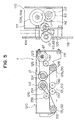
- Figure 5 is a top view showing a schematic arrangement of the winding device being a second embodiment of the present invention.
- Figure 6A is a front sectional view of the main part in an example of the drum fixed structure on the winding device being a second embodiment of the present invention and Figure 6B is a side sectional view along the line VIB-VIB.
- Figure 7 is a perspective view showing an auto-winder being one example of the winding device being a second embodiment of the present invention.
- Figure 8 is a perspective view showing a removable belt traverse being the main part of Figure 7.
- Firstly, a first embodiment of the present invention will be described using Figures 1 and 2. Figure 1 shows a schematic arrangement of one example of a winding device A being a first embodiment of the present invention.
- A
winding system 1 comprises apulley 3 connected to the drive shaft of amotor 2 being the drive source, apulley 5 to which the drive force is transmitted from thepulley 3 by abelt 4 and a friction drum 6 (hereafter, referred to simply as a drum) connected to thepulley 5 and that contacts the periphery of a package P. The drive force of themotor 2 is transmitted to thedrum 6 via thepulley 3,belt 4 andpulley 5 and winding of a yarn S is performed by applying a rotational drive force to the package P by the contact rotation of thisdrum 6. A guide groove 7 for preventing yarn stitching is arranged in part of the circumferential direction close to the left and right ends of the surface of thedrum 6. - It should be noted that the structure (bent angles or the like) of these left and right guide grooves 7 differ between the large diameter side and small diameter side.
- The drive force of the
motor 2 is transmitted to thetraverse system 20 via thespeed change system 10 by the system described hereafter. The rotational drive force of themotor 2 is transmitted to theinput side gear 10A of thespeed change system 10 via a gear a1 linked to the rotation shaft of the drum, a gear b1 that engages with the gear a1 and a gear c1 linked to the gear b1 and on the same shaft. Due to the rotational driving of theinput side gear 10A, the output side gear 10b rotates at a under predetermined speed change conditions and this speed varying rotational drive force is transmitted to thetraverse system 20. - The
traverse system 20 is for moving a set (two) ofsynchronous toothed belts 22,23 (traverse belts) arranged horizontally above each other and each provided withtraverse guides 21 that catch the yarn S, in opposite directions to each other and comprisessynchronous toothed belts pulleys - It should be noted that the
pulleys synchronous toothed belts pulley 29 rotates freely with respect to these. Similarly, thepulleys synchronous toothed belts pulley 31 rotates freely with respect to these. Due to this arrangement, one set ofsynchronous toothed belts - The rotational drive force of the
output side gear 10B of thespeed change system 10 is output to the gear d1 making thepulley 26 connected to the same shaft rotate. Due to the rotation of thepulley 26, thesynchronous toothed belt 24 arranged on thepulleys aforementioned pulley 28 rotates thepulley 30 connected to the same shaft and drives thesynchronous toothed belt 22 arranged on thepulley 31 in the direction of the arrow. - Conversely, as the
pulley 27 is rotated, the gear e connected to the same shaft aspulley 27 rotates and the gear f1 that engages with this gear e1 is rotated in the opposite direction. Thus thepulley 34 connected to the same shaft as gear f1 rotates, thesynchronous toothed belt 25 is driven by the rotation of thatpulley 34 and thepulley 33 is rotated. As a result, thesynchronous toothed belt 23 arranged on thepulley 29 is driven in the opposite direction tosynchronous toothed belt 22 by thepulley 32 rotating. - Due to this arrangement, the
traverse system 20 is able to reciprocally move the yarn S within a predetermined range equivalent to the winding width of the package P due to the transfer of the yarn S from thetraverse guide 21 of the uppersynchronous toothed belt 22 to the traverse guide (not shown in the drawings) of the lowersynchronous toothed belt 23. - Next, the structure and speed change functions of the
speed change system 10 will be described. - As shown in Figure 2, the
rotation shaft 11 of theinput side gear 10A and therotation shaft 12 of theoutput side gear 10B on thespeed change system 10 are arranged as non-aligned shafts where the center of rotation is eccentric. In short, as shown in Figure 2A, therotation shaft 11 of theinput side gear 10A and therotation shaft 12 of theoutput side gear 10B are positioned such that the centers of rotation of each r1,r2 are eccentric by the distance X and furthermore, afirst disk 13 is arranged on the tip of therotation shaft 11 of theinput side gear 10A and asecond disk 14 is arranged on the tip of therotation shaft 12 of theoutput side gear 10B. Also, apin 15 fixed in a suitable place in thefirst disk 13 connects bothdisks long hole 16 arranged in thesecond disk 14. - Due to the above arrangement, the rotational drive force of the
input side gear 10A is transferred to theoutput side gear 10B by thepin 15 connecting thefirst disk 13 and thesecond disk 14. As shown in figure 2B, as the center of rotation r1 of thefirst disk 13 and the center of rotation r2 of thesecond disk 14 are eccentric by the distance X, the distance from the center of rotation r2 of thesecond disk 14 to thepin 15 gradually changes while thefirst disk 13 is rotating. In short, this means that thepin 15 rotates at a uniform peripheral velocity but during this rotation, the angular speed of thesecond disk 13 changes over time as the rotational radius from thepin 15 to the center of rotation r2 of thesecond disk 14 changes. As a result, while thefirst disk 13 makes one revolution at a uniform speed, thesecond disk 14 makes one revolution at a non-uniform speed. Accordingly, as the rotational velocity of the rotational drive force output to thetraverse system 20 through theoutput side gear 10B connected to thesecond disk 14 changes over a fixed cycle, the movement speed of thetraverse belts - On the
speed change system 10 using these non-aligned shafts, one revolution is one cycle of speed variation. Conversely, when a cone package is to be formed, it is necessary to increase the traverse speed at the small diameter part and decrease the traverse speed at the large diameter part. Accordingly, the traversing of the yarn S completes one reciprocal movement for each one revolution of the input/output side gears 10A,10B of thespeed change system 10 and the intended cone package may be obtained if the traverse speed is maximized at the smallest diameter part on the cone package and minimized at the largest diameter part of the package P. - It should be noted that if the dimension of from the center of rotation r1 of the
first disk 13 to the center of thepin 15 is given the symbol R and the amount of eccentricity between thefirst disk 13 and thesecond disk 14 is given the symbol X, the speed change ratio is defined as (R+X)/(R-X). For normal cone winding, the speed change ratio is set around 1.3 but by changing the value of the amount of eccentricity X, the formation of a cone package having the desired shape corresponding to each type of specifications is possible by changing the speed change ratio non-graduatedly. Furthermore, if it is possible to set the speed change ratio to 1, the formation of a cheese package is also possible. - It should be noted that the changing of the speed change ratio is possible by fixing the position of the
input side gear 10A andfirst disk 13 and increasing or reducing the amount of eccentricity X by moving theoutput side gear 10B andsecond disk 14 in a direction at right angles to the rotation shaft. However, in this case, as can be understood from Figure 1, by changing the position of theoutput side gear 10B, the position of thepulley 26 and the gear d1 that inputs rotational drive force into thetraverse system 20 must also be changed. Thus, a tension pulley (not shown in the drawings) is arranged with respect to the synchronoustoothed belt 24 and it is preferable to adjust the belt tension using this. - The first embodiment of the present invention is not limited to that stated here and does not disclude suitable modifications in response to various conditions. For example, although not shown in the drawings, a wing traverse system or equi-velocity cam traverse system may be utilized as a traverse device.
- Next, using Figures 3 to 6, a second embodiment of the present invention will be described. Figure 3 shows a schematic arrangement of one example of the winding device A being a second embodiment of the present invention.
- This winding device A is provided with a drive source such as a
motor 102 or the like, apulley 105 to which the drive force is transmitted via abelt 104 from apulley 103 linked to adrive shaft 102a of themotor 102, and a friction drum 106 (hereafter, referred to simply as a drum 106) connected to arotation shaft 106a of thepulley 105 and is in contact with the periphery of the packageP. Guide grooves 107 for preventing yarn stitching are formed in part of the circumferential direction near both the left and right ends on the periphery of thedrum 106. - The drive force of the
motor 102 is transmitted from thepulley 103 to thepulley 105 via thebelt 104 and the rotational drive force is transmitted from thatpulley 105 to thespeed change system 10 of the traverse device T anddrum 106. Thedrum 106 is arranged such that the yarn S is wound with a tapered paper tube Q as the core by rotating the package P. - The traverse device T comprises
speed change system 110 and traversesystem 120 connected to this. The system that transmits the drive force of themotor 102 from thespeed change system 110 of the traverse device T to thetraverse system 120 is as described hereafter. The rotational drive force of themotor 102 is input into thespeed change system 110 from the gear a2 linked to therotation shaft 106a of thedrum 106. In short, is transmitted to theprimary side gear 110A via the gear b2 that engages with the gear a2 (in the present embodiment, the gears a2,b2 are bevel gears) and the gear c2 that is linked to the same shaft as gear b2. Due to the driving of theprimary side gear 110A, thesecondary side gear 110B rotates under predetermined speed change conditions by the system described hereafter and that speed varied rotational drive force rotates the gear d2 that engages with thesecondary side gear 110B and the gear e2 linked to the same shaft as gear d2. Also, the drive force is transmitted to the input gear g2 of thetraverse system 120 through the output gear f2 that engages with the gear e2. - The
traverse system 120 rotates the traverse belts 121,122 arranged parallel above each other and provided with traverse guides 140 on each that connect with the yarn S, in opposite directions to each other and as shown in Figure 5, is arranged as a unit removable by abolt 119 from a frame 117,118 that supports thespeed change system 110. The arrangement of thetraverse system 120 comprises not only traverse belts 121,122 but also synchronous toothed belts 125,126, pulleys 123,124,128-134 and input gear g2, gears j2 and k2. It should be noted that gears j2 and k2 are mounted at a position from which a removing operation is possible from the outer side. - The
upper traverse belt 121 is arranged between the pulleys 130,131 and thelower traverse belt 122 is arranged between pulleys 129,132. Thepulley 123 is linked to the same shaft as the input gear g2 that engages with output gear f2 of thespeed change system 110 and a synchronoustoothed belt 125 is arranged between thispulley 123, thepulley 124 andpulley 128. Furthermore, the synchronoustoothed belt 126 is arranged between the pulleys 133,134. The gear j2 andpulley 124 as well as gear k2 andpulley 134 of which both sets are arranged on the same shaft, rotate in unison and moreover, the gear j2 and gear k2 are arranged such that they move while engaging. - Of the pulleys 128,129,130 arranged on the same shaft, the
pulleys pulley 129 rotates freely with respect to the other two. Similarly, of the pulleys 131,132,133 arranged on the same shaft, thepulleys pulley 131 rotates freely with respect to the other two. It should be noted that the aforementioned pulleys 128,129,130 arranged on the same shaft and the pulleys 131,132,133 are arranged so as to each be removable by aboss 141 andboss 142 respectively (refer to Figure 4). - It should be noted that the tension pulleys 135-138 ommitted from Figures 3 and 4 are inserted in Figure 5 showing the schematic arrangement of the
traverse system 120 when viewed from above. Thetension pulley 135 is for adjusting the tension of theupper traverse belt 121, thetension pulley 136 is for adjusting the tension of thelower traverse belt 122, thetension pulley 137 is for adjusting the tension of the synchronoustoothed belt 125 arranged between the pulleys 123,124,128 and thetension pulley 138 is for adjusting the tension of the synchronoustoothed belt 126 arranged between the pulleys 133,134. - The rotational drive force input into the input gear g2 from the output gear f2 of the
speed change system 10 is transmitted to thepulley 123. Due to this, the synchronoustoothed belt 125 arranged between the pulleys 123,124,128 is driven and thetraverse belt 121 arranged between the pulleys 130,131 moves in the direction of the arrow (refer to Figure 3) due to the rotation of thepulley 130 linked to the same shaft aspulley 128. - Due to the rotation of the
aforementioned pulley 124, the gear j2 linked to the same shaft rotates and the gear k2 that engages with this is rotated in the opposite direction. Thus as thepulley 134 linked to the same shaft rotates, thepulley 133 rotates via the synchronoustoothed belt 126. As a result, thepulley 132 linked to the same shaft rotates and thetraverse belt 122 arranged between the pulleys 129,132 moves in the opposite direction to theaforementioned traverse belt 121. - Due to the aforementioned arrangement, the upper and lower traverse belts 121,122 move in opposite directions to each other. Then due to the transfer of the yarn S between the upper and lower traverse guides 140,140 arranged on each of the traverse belts 121,122 respectively, the yarn S is able to be reciprocally moved within a predetermined range equivalent to the winding width of the package P.
- Similar to the first embodiment, the changing of the speed change ratio is possible by fixing the position of the
primary side gear 110A andfirst disk 113 and increasing or reducing the amount of eccentricity by moving thesecondary side gear 110B andsecond disk 114 in a direction at right angles to the rotation shaft. However, in the case of the second embodiment, as it becomes necessary to change the position of the gears d2 and e2 in association with the positional change of thesecondary side gear 110B, the spacing of the gear e2 and the input gear g2 of thetraverse system 120 changes. However, changing the position of the input gear g2 is difficult. Thus in this second embodiment, the output gear f2 is movable and moreover, it's diameter is larger than the spacing between the gear e2 and gear g2 and by changing the gear position such that it suitable engages corresponding to the increase or decrease in the spacing between the gears e2,g2, this problem is solved. - When the traverse device T is to be used on a yarn winding device, the following
adjustment operations 1 ○ through 3 ○ are necessary. - 1 ○ Adjustment of the yarn transfer position between the traverse guides arranged on the traverse belts.
- Normally, the upper and lower traverse guides are set so that both the left and right sides of the traverse belts overlap.
- 2 ○ Adjustment of the transfer position between the traverse guides and the speed change cycle of the speed change system.
- In short, this must be set such that the yarn traverse speed is maximized at the smallest diameter part of the package and minimized at the largest diameter part.
- 3 ○ Setting of the drum position such that the yarn contacts the guide groove in the drum periphery for preventing yarn stitching at the time of yarn transfer.
- In order to easily carry out each of the aforementioned adjustment operations, the following arrangements a through d are utilized by the second embodiment.
- (a) Forming the
traverse system 120 into a unit and making it removable. - (b) An arrangement such that the drive force is transmitted by the
engagement of the output gear f2 of the
speed change system 110 and the input gear g2 of thetraverse system 120, and a setting such that the output gear f2 and input gear g2 engage due to the mounting of thetraverse system 120. - (c) An arrangement such that the gear k2 of the
traverse system 120 may be removable and the removing operation of that gear k2 from the outer side may be performed. - (d) The utilization of a taperlock system such that the drum may be fixed at the desired rotation position.
-
- The aforementioned
transfer position adjustment 1 ○ is performed as described hereafter. Thetraverse system 120 is removed from the traverse device T and the gear k2 removed. The desired tension is then applied to each of the traverse belts 121,122 and synchronous toothed belts 125,126 arranged between the pulleys by the tension pulleys 136-138 (refer to Figure 5) and the traverse guides 140,140 are adjusted such that one of the traverse belts 121,122 overlap at one end in the vertical direction. This state is then held by a suitable tool and if the gear k2 is attached and engages with the gear j2, the transfer position of the yarn S between the traverse guides 140,140 is fixed in the correct state. It should be noted that the aforementioned operation may be performed with the gear j2 being removable. - Next, the aforementioned
timing adjustment operation 2 ○ will be described. Firstly, the phase of thespeed change system 110 is adjusted such that it is the same as thetraverse system 120. In short, the positional relationship between theprimary side gear 110A andsecondary side gear 110B is adjusted such that the speed variation conditions are in alignment with the traverse guide position afteradjustment 1 ○ (the rotational velocity has been either maximized or minimized). If a marking that shows the position where the rotational velocity of thesecondary side gear 110B is at a maximum (or minimum) , is performed on the frame or the like that supports thespeed change system 110, the aforementioned adjustment operation is extremely simple. In continuance, based on the aforementioned procedure, after the yarn transfer position has been correctly adjusted, thetraverse system 120 that has been held in this state by a suitable tool is fixed to the predetermined place on the frame 118 (refer to Figure 5) by 3 or 4bolts 119 and the input gear g2 is engaged with the output gear f2. Due to this, a state where the yarn transfer timing and speed variation of the traverse speed have been correctly adjusted may be obtained. - Concerning the aforementioned 3 ○ , after performing the adjustments of the yarn transfer position, transfer timing and speed variation conditions, the traverse guide is held in the yarn transfer position and the position of the
drum 106 is adjusted and fixed so that it is in alignment with this held state. Thedrum 106 of the present embodiment is arranged such that it may be fixed at a desired angle (phase) with respect to therotation shaft 106a by a tapered fixingmember 108 positioned on the end as shown in Figures 4 and 6. - As shown in Figure 6, the fixing
member 108 comprisesfirst taper members rotating shaft 106a,second taper members drum 106, andbolts rotation shaft 106a. Furthermore, ahole 108d into which may be freely inserted thebolt 108c is formed in thefirst taper member 108a and ascrew hole 108e into which thebolt 108c may be screwed is formed in thesecond taper member 108b. Thebolt 108c is inerted into thehole 108d of thefirst taper member 108a and by tightening by screwing into thescrew hole 108e of thesecond taper member 108b, thesecond taper member 108b is pulled by thefirst taper member 108a. Due to this, bothtaper members first taper member 108a presses the outer periphery of therotation shaft 106a, thesecond taper member 108b presses the inner periphery of thedrum 106 and as a result, thedrum 106 androtation shaft 106a are fixed so as to rotate in unison. - In the present embodiment, it is possible to fix the
drum 106 at a desired angle (phase) with respect to therotation shaft 106a due to the fixingmember 108. Accordingly, if a marking that shows thecorrect drum 106 position during the yarn S transfer, is performed on the frame or the like that supports thedrum 106, the position adjustment operations of thedrum 106 may be performed extremely easily and as a result, the contact state of the yarn S with theguide groove 107 at the time of transfer is correct and yarn stitching may be reliable prevented. - Figure 7 shows the entire arrangement of an auto-
winder 150 being one example of the winding device being a second embodiment of the present invention and Figure 8 shows those main parts. The auto-winder 150 shown forms a cone package by winding the yarn S on a tapered paper tube Q held so as to be removable by the uppermost cradle 151 while unwinding the yarn S from ansupply yarn package 160. It should be noted that the auto-winder of figures 8 and 9 may be used as winding devices being the first embodiment of the present invention. - In the second embodiment of the present invention, the part (refer to Figure 8), of the belt traverse device T, comprising the
drum 106 that applies a rotational drive force to the paper tube Q and thetraverse system 120 that traverses the yarn S to the left and right is an arrangement removable as a single unit by a bolt from theframe 159 of thewinder 150 and thespeed change system 110 and a mechanical element for transmitting the rotational drive force of themotor 102 to that speed change system 110 (in short,belt 104,pulley 105 and gears a2,b2,c2) are stored inside theframe 159. - Furthermore, as the marking for aligning the phase of the
speed change system 110 to thetraverse system 120 is easily visible from the outer side, it is preferable to arrange a winder or the like (not shown in the drawings) in a location on theframe 159. - Hereafter, the actions of the aforementioned auto-
winder 150 will be described. When normal winding is to be performed, the yarn S unwound from thesupply yarn package 160 is rewound onto the tapered paper tube Q rotated by thedrum 106 after being made to follow theguide 157. The yarn S at this time is traversed to the left and right while the speed is increased and decreased in the uniform cycle ideal for forming a cone package. During this winding operation, ayarn defect detector 153 inspects whether there are any yarn defects in the yarn Y and furthermore, atensor 156 controls the tension of the yarn S. - When the
yarn defect detector 153 detects some kind of defect or abnormality in the yarn S, the driving of thedrum 106 by themotor 102 is stopped and the yarn S is cut by a cutter provided on theyarn defect detector 153. The supply side part of the cut yarn S (lower yarn) is sucked by the continuously sucking loweryarn sucking mouth 155. Conversely, the winding side part of the cut yarn S (upper yarn) is wound on to the paper tube Q by thedrum 106 rotating by inertial rotation. In continuance, the yarn S is slightly payed out by reverse rotating thedrum 106 and after grabbing the upper yarn be rotating the upperyarn suction member 158 upwards, the grasped upper yarn is guided to theyarn piecing device 152 by rotating the upperyarn suction member 158 downwards. Conversely, after grasping the lower yarn sucked into the loweryarn suction mouth 155 by rotating the loweryarn suction member 158 downwards, it is once again rotated upwards and the grasped lower yarn is guided to theyarn piecing device 152. In this way, the upper and lower yarns guided to theyarn piecing device 152 are joined by a rotating air current at theyarn piecing device 152. After the yarn piecing processing is complete, the rotation of themotor 102 in the forward direction restarts and the winding of the yarn S resumes. - The present invention does not preclude suitable modifications corresponding to other conditions.
- As shown by the above description, the winding device of the present invention is able to reliably form a cone package by a simple arrangement. Furthermore, by changing the speed of the traverse system, a winding state suitable for each of the small diameter part and large diameter part when forming a package is realised. There is no increase in the mechanical load on the winding system and there is no danger of slippage being generated between the package and friction drum. In particular, by arranging the traverse system as a belt traverse system that may be arranged as a low inertia rotating member, the problems such as mechanical load and noise may be reduced and speed variation may be more quickly and more relaiably performed by the speed change system.
- Furthermore, as the present invention is a simple arrangement achieved by utilizing a system whereby the speed change ratio is changed by increasing or decreasing the amount of eccentricity, it is possible to non-graduatedly change the speed change ratio on an identical device.
- Yet further, as the present invention has a removable traverse system and as the means for transmission of the drive force from the speed change system to the traverse system is comprised of engaged gears, after independently performing the phase adjustments of each of the traverse system and speed change system, botthe phases of both may be aligned by simply mounting the traverse system and engaging the gears. Accordingly, the number of necessary operations is decreased and results in operation only at the front of the device thus making the yarn transfer adjustment operations extremely simple. Furthermore, as a result, the time when the device must be stopped for maintenance is reduced.
- As the contact location of the speed change system and traverse system is positioned between the output gear and input gear, the contact operation for both is simplified and moreover, the engagement of the output gear and input gear is reliable.
- Due to the arrangement of both the output gear of the speed change system and the input gear of the traverse system as flat gears, the engagement of both is simple and thus operability is improved.
Claims (6)
- A winding device provided with a winding system (1) having a friction drum (6) connected to a drive source such a motor (2) or the like and that rotates in contact with a package (P), and a traverse system for traversing a yarn to be wound on the package,
wherein the traverse system (20) is a belt traverse system having a set of traverse belts (22, 23) that move in opposite directions to each other and which is connected to the winding system (1)
characterized in that
the winding system (1) is connected to the traverse system (20) via a mechanical transmission (3, 4, 5, a1, b1, c1, 10a, d1, 24, 27) comprising a speed change system (10) which enables the traverse speed to be adjusted. - A winding device as in claim 1, wherein the speed change system (10) has nonaligned axes (r1, r2) for which the amount of eccentricity may be adjusted.
- A winding device according to claim 1, wherein the means for transmitting drive force from the speed change system (10) to the traverse system (20) comprises engaging gears (k2, j2) which are mounted at a position from which a removing operation is possible from the outer side.
- A winding device as in claim 3, wherein the connecting part of the traverse system (20) and speed change system (10) is positioned between a shaft of an input gear (f1) of the traverse system (20) and a shaft of an output gear (10B) of the speed change system (10).
- A winding device as in claim 1, wherein a coupling assembly (108) comprising taper members (108a, 108b) is provided for connecting the friction drum (106) to a rotating shaft (106a).
- A winding device as in claim 5, wherein the coupling assembly comprises first taper members (108a) that contact the outer periphery of the shaft (106a), second taper members (108b) that contact the inner periphery of the drum (106), and bolts (108c).
Applications Claiming Priority (3)
| Application Number | Priority Date | Filing Date | Title |
|---|---|---|---|
| JP260733/96 | 1996-10-01 | ||
| JP26073396 | 1996-10-01 | ||
| JP26073396A JPH10109823A (en) | 1996-10-01 | 1996-10-01 | Winding device |
Publications (3)
| Publication Number | Publication Date |
|---|---|
| EP0834462A2 EP0834462A2 (en) | 1998-04-08 |
| EP0834462A3 EP0834462A3 (en) | 1998-05-27 |
| EP0834462B1 true EP0834462B1 (en) | 2002-05-22 |
Family
ID=17352002
Family Applications (1)
| Application Number | Title | Priority Date | Filing Date |
|---|---|---|---|
| EP19970115964 Expired - Lifetime EP0834462B1 (en) | 1996-10-01 | 1997-09-13 | Winding device |
Country Status (3)
| Country | Link |
|---|---|
| EP (1) | EP0834462B1 (en) |
| JP (1) | JPH10109823A (en) |
| DE (1) | DE69712695T2 (en) |
Families Citing this family (4)
| Publication number | Priority date | Publication date | Assignee | Title |
|---|---|---|---|---|
| JP2000198621A (en) * | 1999-01-07 | 2000-07-18 | Murata Mach Ltd | Traversing device of automatic winder |
| JP2012017205A (en) | 2010-07-09 | 2012-01-26 | Murata Machinery Ltd | Yarn winding device |
| CN108190625A (en) * | 2017-12-27 | 2018-06-22 | 河南华通电缆股份有限公司 | A kind of assemble method of bi-motor cable bracket device for producing cable and wire equipment |
| CN114157110B (en) * | 2021-12-14 | 2022-09-02 | 佛山市顺德区乐普达电机有限公司 | Full-automatic winding structure is used in food processing motor production |
Family Cites Families (7)
| Publication number | Priority date | Publication date | Assignee | Title |
|---|---|---|---|---|
| FR836117A (en) * | 1938-01-12 | 1939-01-11 | Ryo Catteau | Wire guide device in crossed wire winders |
| US3491604A (en) * | 1968-02-12 | 1970-01-27 | Cass B Levi | Device for modifying rotary motion |
| IT1133139B (en) * | 1979-09-25 | 1986-07-09 | Terrell Mach Co | APPARATUS AND METHOD FOR WRAPPING WIRE TO FORM A PACK |
| JPS594571A (en) * | 1982-06-30 | 1984-01-11 | Asahi Chem Ind Co Ltd | String traversing device |
| IT1168668B (en) * | 1983-04-12 | 1987-05-20 | Cefin Spa | DEVICE FOR THE TRANSFORMATION OF A UNIFORM ROTARY MOTORCYCLE INTO A VARIABLE SPEED ROTARY MOTORCYCLE |
| DE3603803A1 (en) * | 1986-02-07 | 1987-08-13 | Schlafhorst & Co W | Cross-winding machine |
| DE4310905A1 (en) * | 1993-04-02 | 1994-10-06 | Schlafhorst & Co W | Method and apparatus for laying a thread on a cross-wound bobbin |
-
1996
- 1996-10-01 JP JP26073396A patent/JPH10109823A/en active Pending
-
1997
- 1997-09-13 DE DE1997612695 patent/DE69712695T2/en not_active Expired - Fee Related
- 1997-09-13 EP EP19970115964 patent/EP0834462B1/en not_active Expired - Lifetime
Also Published As
| Publication number | Publication date |
|---|---|
| EP0834462A2 (en) | 1998-04-08 |
| DE69712695D1 (en) | 2002-06-27 |
| JPH10109823A (en) | 1998-04-28 |
| DE69712695T2 (en) | 2003-01-30 |
| EP0834462A3 (en) | 1998-05-27 |
Similar Documents
| Publication | Publication Date | Title |
|---|---|---|
| EP1880964B1 (en) | High-frequency thread-guide device for the production of bobbins with modulated traversing | |
| EP1880963A2 (en) | Thread-guide device for the production of bobbins with traversing modulation | |
| US20090134263A1 (en) | Method for Avoiding Ribbon Windings | |
| US4371122A (en) | Method and apparatus for winding strand material and package | |
| EP0834462B1 (en) | Winding device | |
| EP3383780B1 (en) | A method to position spindle precisely in turret type automatic winder | |
| US5033686A (en) | Apparatus with at least one reeling station for producing the winding of a cheese | |
| EP0902107B1 (en) | Multiple twister | |
| US5277668A (en) | Gear transmissions, for textile machines | |
| JPH08299763A (en) | Method for bundling hollow fiber membrane, winding and shaping machine, and feeder | |
| EP0060570B1 (en) | Grooved roller for a winding machine | |
| EP1018479A2 (en) | Traverse device for automatic winder | |
| US6726142B2 (en) | Twist controlling device, rotatable nip and axial feed system | |
| EP0612683B1 (en) | Multi-thread take-up machine | |
| JPH05162924A (en) | Thread wind-up apparatus | |
| JP2756831B2 (en) | Precision winder | |
| JP4384324B2 (en) | Take-up winder | |
| KR200350803Y1 (en) | A traverse electronic drive device by combination of servo motor and timing belt of the twisting machine | |
| KR200241812Y1 (en) | Unannounced transmission of winder machine | |
| JP3675848B2 (en) | Turret type winder thread switching device | |
| JPH10250938A (en) | Belt traverse device | |
| JPH10338418A (en) | Belt traverse device | |
| JPS6158385B2 (en) | ||
| SU1655884A1 (en) | Apparatus for coiling fibrous material | |
| JP2591589Y2 (en) | Supply bobbin coaxial winding device |
Legal Events
| Date | Code | Title | Description |
|---|---|---|---|
| PUAI | Public reference made under article 153(3) epc to a published international application that has entered the european phase |
Free format text: ORIGINAL CODE: 0009012 |
|
| AK | Designated contracting states |
Kind code of ref document: A2 Designated state(s): CH DE IT LI |
|
| AX | Request for extension of the european patent |
Free format text: AL;LT;LV;RO;SI |
|
| PUAL | Search report despatched |
Free format text: ORIGINAL CODE: 0009013 |
|
| AK | Designated contracting states |
Kind code of ref document: A3 Designated state(s): AT BE CH DE DK ES FI FR GB GR IE IT LI LU MC NL PT SE |
|
| AX | Request for extension of the european patent |
Free format text: AL;LT;LV;RO;SI |
|
| 17P | Request for examination filed |
Effective date: 19980626 |
|
| AKX | Designation fees paid |
Free format text: CH DE IT LI |
|
| RBV | Designated contracting states (corrected) |
Designated state(s): CH DE IT LI |
|
| 17Q | First examination report despatched |
Effective date: 20000211 |
|
| GRAG | Despatch of communication of intention to grant |
Free format text: ORIGINAL CODE: EPIDOS AGRA |
|
| GRAG | Despatch of communication of intention to grant |
Free format text: ORIGINAL CODE: EPIDOS AGRA |
|
| GRAG | Despatch of communication of intention to grant |
Free format text: ORIGINAL CODE: EPIDOS AGRA |
|
| GRAH | Despatch of communication of intention to grant a patent |
Free format text: ORIGINAL CODE: EPIDOS IGRA |
|
| GRAH | Despatch of communication of intention to grant a patent |
Free format text: ORIGINAL CODE: EPIDOS IGRA |
|
| GRAA | (expected) grant |
Free format text: ORIGINAL CODE: 0009210 |
|
| REG | Reference to a national code |
Ref country code: CH Ref legal event code: EP |
|
| REF | Corresponds to: |
Ref document number: 69712695 Country of ref document: DE Date of ref document: 20020627 |
|
| REG | Reference to a national code |
Ref country code: CH Ref legal event code: NV Representative=s name: KIRKER & CIE SA |
|
| PLBE | No opposition filed within time limit |
Free format text: ORIGINAL CODE: 0009261 |
|
| STAA | Information on the status of an ep patent application or granted ep patent |
Free format text: STATUS: NO OPPOSITION FILED WITHIN TIME LIMIT |
|
| 26N | No opposition filed |
Effective date: 20030225 |
|
| PGFP | Annual fee paid to national office [announced via postgrant information from national office to epo] |
Ref country code: CH Payment date: 20060914 Year of fee payment: 10 |
|
| PGFP | Annual fee paid to national office [announced via postgrant information from national office to epo] |
Ref country code: IT Payment date: 20060930 Year of fee payment: 10 Ref country code: DE Payment date: 20060930 Year of fee payment: 10 |
|
| REG | Reference to a national code |
Ref country code: CH Ref legal event code: PL |
|
| PG25 | Lapsed in a contracting state [announced via postgrant information from national office to epo] |
Ref country code: LI Free format text: LAPSE BECAUSE OF NON-PAYMENT OF DUE FEES Effective date: 20070930 Ref country code: DE Free format text: LAPSE BECAUSE OF NON-PAYMENT OF DUE FEES Effective date: 20080401 Ref country code: CH Free format text: LAPSE BECAUSE OF NON-PAYMENT OF DUE FEES Effective date: 20070930 |
|
| PG25 | Lapsed in a contracting state [announced via postgrant information from national office to epo] |
Ref country code: IT Free format text: LAPSE BECAUSE OF NON-PAYMENT OF DUE FEES Effective date: 20070913 |