EP4410664A1 - Ship maneuvering system, ship control device, ship control method, and program - Google Patents
Ship maneuvering system, ship control device, ship control method, and program Download PDFInfo
- Publication number
- EP4410664A1 EP4410664A1 EP22875837.1A EP22875837A EP4410664A1 EP 4410664 A1 EP4410664 A1 EP 4410664A1 EP 22875837 A EP22875837 A EP 22875837A EP 4410664 A1 EP4410664 A1 EP 4410664A1
- Authority
- EP
- European Patent Office
- Prior art keywords
- watercraft
- actuator
- moment
- control device
- operation unit
- Prior art date
- Legal status (The legal status is an assumption and is not a legal conclusion. Google has not performed a legal analysis and makes no representation as to the accuracy of the status listed.)
- Pending
Links
- 238000000034 method Methods 0.000 title claims description 102
- 238000001514 detection method Methods 0.000 description 31
- 230000003247 decreasing effect Effects 0.000 description 27
- 230000007704 transition Effects 0.000 description 27
- 230000006870 function Effects 0.000 description 19
- 238000004891 communication Methods 0.000 description 10
- 238000010586 diagram Methods 0.000 description 8
- 238000005516 engineering process Methods 0.000 description 8
- 230000000052 comparative effect Effects 0.000 description 7
- 230000006399 behavior Effects 0.000 description 4
- 230000000694 effects Effects 0.000 description 4
- 230000000994 depressogenic effect Effects 0.000 description 3
- 238000013016 damping Methods 0.000 description 1
- 230000000881 depressing effect Effects 0.000 description 1
- 238000005259 measurement Methods 0.000 description 1
- 238000012986 modification Methods 0.000 description 1
- 230000004048 modification Effects 0.000 description 1
- 230000002093 peripheral effect Effects 0.000 description 1
- 238000006467 substitution reaction Methods 0.000 description 1
- XLYOFNOQVPJJNP-UHFFFAOYSA-N water Substances O XLYOFNOQVPJJNP-UHFFFAOYSA-N 0.000 description 1
Images






Classifications
-
- B—PERFORMING OPERATIONS; TRANSPORTING
- B63—SHIPS OR OTHER WATERBORNE VESSELS; RELATED EQUIPMENT
- B63H—MARINE PROPULSION OR STEERING
- B63H21/00—Use of propulsion power plant or units on vessels
- B63H21/21—Control means for engine or transmission, specially adapted for use on marine vessels
-
- B—PERFORMING OPERATIONS; TRANSPORTING
- B63—SHIPS OR OTHER WATERBORNE VESSELS; RELATED EQUIPMENT
- B63H—MARINE PROPULSION OR STEERING
- B63H21/00—Use of propulsion power plant or units on vessels
- B63H21/21—Control means for engine or transmission, specially adapted for use on marine vessels
- B63H21/213—Levers or the like for controlling the engine or the transmission, e.g. single hand control levers
-
- B—PERFORMING OPERATIONS; TRANSPORTING
- B63—SHIPS OR OTHER WATERBORNE VESSELS; RELATED EQUIPMENT
- B63H—MARINE PROPULSION OR STEERING
- B63H25/00—Steering; Slowing-down otherwise than by use of propulsive elements; Dynamic anchoring, i.e. positioning vessels by means of main or auxiliary propulsive elements
- B63H25/02—Initiating means for steering, for slowing down, otherwise than by use of propulsive elements, or for dynamic anchoring
-
- B—PERFORMING OPERATIONS; TRANSPORTING
- B63—SHIPS OR OTHER WATERBORNE VESSELS; RELATED EQUIPMENT
- B63H—MARINE PROPULSION OR STEERING
- B63H25/00—Steering; Slowing-down otherwise than by use of propulsive elements; Dynamic anchoring, i.e. positioning vessels by means of main or auxiliary propulsive elements
- B63H25/42—Steering or dynamic anchoring by propulsive elements; Steering or dynamic anchoring by propellers used therefor only; Steering or dynamic anchoring by rudders carrying propellers
-
- B—PERFORMING OPERATIONS; TRANSPORTING
- B63—SHIPS OR OTHER WATERBORNE VESSELS; RELATED EQUIPMENT
- B63H—MARINE PROPULSION OR STEERING
- B63H25/00—Steering; Slowing-down otherwise than by use of propulsive elements; Dynamic anchoring, i.e. positioning vessels by means of main or auxiliary propulsive elements
- B63H25/50—Slowing-down means not otherwise provided for
-
- B—PERFORMING OPERATIONS; TRANSPORTING
- B63—SHIPS OR OTHER WATERBORNE VESSELS; RELATED EQUIPMENT
- B63H—MARINE PROPULSION OR STEERING
- B63H20/00—Outboard propulsion units, e.g. outboard motors or Z-drives; Arrangements thereof on vessels
- B63H2020/003—Arrangements of two, or more outboard propulsion units
-
- B—PERFORMING OPERATIONS; TRANSPORTING
- B63—SHIPS OR OTHER WATERBORNE VESSELS; RELATED EQUIPMENT
- B63H—MARINE PROPULSION OR STEERING
- B63H21/00—Use of propulsion power plant or units on vessels
- B63H21/21—Control means for engine or transmission, specially adapted for use on marine vessels
- B63H2021/216—Control means for engine or transmission, specially adapted for use on marine vessels using electric control means
-
- B—PERFORMING OPERATIONS; TRANSPORTING
- B63—SHIPS OR OTHER WATERBORNE VESSELS; RELATED EQUIPMENT
- B63H—MARINE PROPULSION OR STEERING
- B63H25/00—Steering; Slowing-down otherwise than by use of propulsive elements; Dynamic anchoring, i.e. positioning vessels by means of main or auxiliary propulsive elements
- B63H25/02—Initiating means for steering, for slowing down, otherwise than by use of propulsive elements, or for dynamic anchoring
- B63H2025/026—Initiating means for steering, for slowing down, otherwise than by use of propulsive elements, or for dynamic anchoring using multi-axis control levers, or the like, e.g. joysticks, wherein at least one degree of freedom is employed for steering, slowing down, or dynamic anchoring
Definitions
- the present invention relates to a watercraft maneuvering system, a watercraft control device, a watercraft control method, and a non-volatile storage medium storing a program.
- Patent Document 1 describes technology for enabling a watercraft to be operated with the feeling of a car.
- a brake pedal for limiting a movement speed of a watercraft body is provided in the watercraft body.
- an output direction of an outdrive device is reversed if the brake pedal is strongly depressed (i.e., a backward propulsion force is generated if the brake pedal is strongly depressed when the watercraft is moving forward) and the watercraft decelerates.
- a moving watercraft is put into a stationary state by depressing the brake pedal and the brake pedal is continuously depressed, fixed point holding control of the watercraft is performed.
- Patent Document 2 if the watercraft operator simply stops an engine or disengages a clutch to stop the watercraft, the watercraft will continue sailing with inertia and move a considerable distance before the watercraft stops. Moreover, as disclosed in Patent Document 2, when the watercraft is sailing at a full forward movement speed, the watercraft operator performs an operation in which the clutch is put into backward movement and the engine speed is slightly increased to stop the watercraft in a short distance.
- the watercraft operator should perform an input operation for bringing the moving watercraft to a stationary state without continuing to move by inertia.
- the watercraft operator should perform an input operation for counteracting an inertial force occurring in the watercraft when the watercraft transitions from a moving state to a stationary state.
- the present invention provides a watercraft maneuvering system, a watercraft control device, a watercraft control method, and a non-volatile storage medium storing a program capable of eliminating any need for a watercraft operator's input operation for counteracting an inertial force and/or a moment of inertia occurring in a watercraft during the transition from an operating state of an actuator to a stopped state of the actuator.
- a watercraft maneuvering system including: an actuator having a function of generating a propulsion force of a watercraft and a function of causing the watercraft to generate a moment; an operation unit configured to receive an input operation of a watercraft operator; and a watercraft control device configured to operate the actuator, wherein, when the operation unit has received an input operation for stopping an operation of the actuator while the watercraft control device is operating the actuator, the watercraft control device operates the actuator without any need for the operation unit to receive the input operation for at least one function of the actuator generating the propulsion force in an opposite direction to a direction of an inertial force occurring in the watercraft and causing the watercraft to generate the moment in an opposite direction to a direction of a moment of inertia occurring in the watercraft.
- a watercraft control device provided in a watercraft maneuvering system including an actuator having a function of generating a propulsion force of a watercraft and a function of causing the watercraft to generate a moment and an operation unit for receiving an input operation of a watercraft operator and configured to operate the actuator, wherein, when the operation unit has received an input operation for stopping an operation of the actuator while the watercraft control device is operating the actuator, the watercraft control device operates the actuator without any need for the operation unit to receive the input operation for at least one function of the actuator generating the propulsion force in an opposite direction to a direction of an inertial force occurring in the watercraft and causing the watercraft to generate the moment in an opposite direction to a direction of a moment of inertia occurring in the watercraft.
- a watercraft control method for use in a watercraft control device provided in a watercraft maneuvering system including an actuator having a function of generating a propulsion force of a watercraft and a function of causing the watercraft to generate a moment and an operation unit for receiving an input operation of a watercraft operator and configured to operate the actuator, the watercraft control method including: a first step of operating the actuator in accordance with an input operation received by the operation unit; and a second step of operating the actuator without any need for the operation unit to receive the input operation for at least one function of the actuator generating the propulsion force in an opposite direction to a direction of an inertial force occurring in the watercraft and causing the watercraft to generate the moment in an opposite direction to a direction of a moment of inertia occurring in the watercraft when the operation unit has received an input operation for stopping an operation of the actuator while the watercraft control device is operating the actuator.
- a non-volatile storage medium storing a program for causing a computer, which is mounted in a watercraft control device provided in a watercraft maneuvering system including an actuator having a function of generating a propulsion force of a watercraft and a function of causing the watercraft to generate a moment and an operation unit for receiving an input operation of a watercraft operator and configured to operate the actuator, to execute: a first step of operating the actuator in accordance with an input operation received by the operation unit; and a second step of operating the actuator without any need for the operation unit to receive the input operation for at least one function of the actuator generating the propulsion force in an opposite direction to a direction of an inertial force occurring in the watercraft and causing the watercraft to generate the moment in an opposite direction to a direction of a moment of inertia occurring in the watercraft when the operation unit has received an input operation for stopping an operation of the actuator while the watercraft control device is operating the actuator.
- a watercraft maneuvering system a watercraft control device, a watercraft control method, and a non-volatile storage medium storing a program capable of eliminating any need for a watercraft operator's input operation for counteracting an inertial force and/or a moment of inertia occurring in a watercraft during the transition from an operating state of an actuator to a stopped state of the actuator.
- a watercraft control method of a comparative example will be described and then embodiments of a watercraft maneuvering system, a watercraft control device, a watercraft control method, and a non-volatile storage medium storing a program of the present invention will be described.
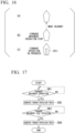
- FIG. 16 is a diagram for describing behavior of a watercraft R11 of a comparative example when an operation unit receives an input operation for moving the watercraft R11 forward and then receives an input operation for stopping the forward movement of the watercraft R11.
- FIG. 17 is a flowchart for describing a process executed in the watercraft R11 of the comparative example.
- step SR1 of FIG. 17 a watercraft control device of the watercraft R11 determines whether or not the operation unit has received the input operation for moving the watercraft R11 forward.
- step SR1 is iteratively executed.
- the process proceeds to step SR2.
- step SR2 the watercraft R11 generates a propulsion force for moving the watercraft R11 forward.
- the watercraft R11 moves forward (i.e., the watercraft R11 moves in an upward direction of FIG. 16 ).
- step SR3 of FIG. 17 the watercraft control device of the watercraft R11 determines whether or not the operation unit has received an input operation for stopping the forward movement of the watercraft R11.
- step SR3 is iteratively executed.
- the process proceeds to step SR4.
- step SR4 the watercraft R11 stops the generation of a propulsion force in the upward direction of FIG. 16 .
- an inertial force in the upward direction of FIG. 16 for trying to continue the forward movement (headway) is generated and the watercraft R11 performs the movement in the upward direction of FIG. 16 (or makes the headway).
- the watercraft operator should perform an input operation for counteracting the inertial force to suppress this headway.
- FIG. 1 is a diagram showing an example of a watercraft maneuvering system 1 including a watercraft 11 to which a watercraft control device 11C of the first embodiment is applied.
- the watercraft control device 11C of the first embodiment can be applied to any type of watercraft 11 such as a personal watercraft (PWC) (a water-motorcycle) having functions similar to those of the PWC described in FIG. 1 of Japanese Patent No. 5196649 , a watercraft not equipped with a jet propulsion device (for example, a watercraft equipped with an outboard motor, a watercraft including an inboard/outboard motor or an inboard engine, a large watercraft including a side thruster, or the like described in Japanese Patent No. 6198192 or Japanese Unexamined Patent Application, First Publication No. 2007-22284 , or the like).
- PWC personal watercraft
- a jet propulsion device for example, a watercraft equipped with an outboard motor, a watercraft including an inboard/outboard motor or an inboard engine, a large watercraft including a side thruster, or the like described in Japanese Patent No. 6198192 or Japanese Unexamined Patent Application, First Publication No. 2007-22284 , or the like).
- the watercraft maneuvering system 1 includes a watercraft 11.
- the watercraft 11 includes an actuator 11A, an operation unit 11B, the watercraft control device 11C, a bow azimuth detection unit 11D, a watercraft speed detection unit 11E, and a watercraft location detection unit 11F.
- the actuator 11A includes a rudder unit 11A1 and a propulsion force generation unit 11A2.
- the rudder unit 11A1 has a function of causing the watercraft 11 to generate a moment.
- the propulsion force generation unit 11A2 has a function of generating a propulsion force of the watercraft 11.
- the actuator 11A includes, for example, an engine, a nozzle, a deflector, a trim actuator, a bucket, a bucket actuator, and the like described in FIG. 1 of Japanese Unexamined Patent Application, First Publication No. 2019-171925 .
- the operation unit 11B receives the input operation of the watercraft operator of the watercraft 11.
- the operation unit 11B includes, for example, a steering unit 11B 1 and a throttle operation unit 11B2.
- the steering unit 11B 1 receives an input operation of the watercraft operator who operates the rudder unit 11A1.
- the throttle operation unit 11B2 receives an input operation of the watercraft operator who operates the propulsion force generation unit 11A2.
- the steering unit 11B 1 and the throttle operation unit 11B2 are configured like a steering handle device described in FIG. 1 of Japanese Patent No. 5196649 , a steering unit described in FIG. 1 of Japanese Unexamined Patent Application, First Publication No. 2019-171925 , and the like.
- the watercraft control device 11C operates the actuator 11A on the basis of the input operation of the watercraft operator of the watercraft 11 received by the operation unit 11B or the like.
- the watercraft control device 11C can operate the actuator 11A so that the propulsion force generation unit 11A2 of the actuator 11A generates a propulsion force for moving the watercraft 11 forward.
- the watercraft control device 11C can operate the actuator 11A so that the propulsion force generation unit 11A2 of the actuator 11A generates a propulsion force for moving the watercraft 11 backward.
- the watercraft control device 11C can operate the actuator 11A so that the actuator 11A causes the watercraft 11 to generate a moment for turning the watercraft 11 in place.
- the watercraft control device 11C can operate the actuator 11A so that the actuator 11A causes the watercraft 11 to generate a propulsion force for moving the watercraft 11 forward and causes the watercraft 11 to generate a moment for turning the watercraft 11.
- the watercraft control device 11C can operate the actuator 11A so that the actuator 11A causes the watercraft 11 to generate a propulsion force for moving the watercraft 11 backward and causes the watercraft 11 to generate a moment for turning the watercraft 11.
- the bow azimuth detection unit 11D detects a bow azimuth of the watercraft 11.
- the bow azimuth detection unit 11D includes, for example, an azimuth sensor.
- the azimuth sensor calculates the bow azimuth of the watercraft 11 using, for example, geomagnetism.
- the azimuth sensor may be a device (a gyrocompass) in which a north-pointing device and a damping device are added to a gyroscope that rotates at a high speed so that north is indicated all the time.
- a gyrocompass a device in which a north-pointing device and a damping device are added to a gyroscope that rotates at a high speed so that north is indicated all the time.
- the azimuth sensor may be a Global Positioning System (GPS) compass that includes a plurality of GPS antennas and calculates the bow azimuth from a relative locational relationship of the plurality of GPS antennas.
- GPS Global Positioning System
- the watercraft speed detection unit 11E detects a speed of the watercraft 11.
- the watercraft speed detection unit 11E may be, for example, a water pressure detection type for detecting a log speed of the watercraft 11 or a GPS measurement type for detecting a ground speed of the watercraft 11.
- the watercraft location detection unit 11F detects a location of the watercraft 11.
- the watercraft location detection unit 11F includes, for example, a GPS device.
- the GPS device calculates location coordinates of the watercraft 11 by receiving signals from a plurality of GPS satellites.
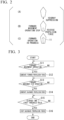
- FIG. 2 is a diagram showing an example of behavior of the watercraft 11 of the first embodiment when the operation unit 11B receives an input operation for moving the watercraft 11 forward and then receives an input operation for stopping the forward movement of the watercraft 11.
- FIG. 3 is a flowchart for describing an example of a process executed by the watercraft control device 11C of the first embodiment when the operation unit 11B receives the input operation for moving the watercraft 11 forward and then receives the input operation for stopping the forward movement of the watercraft 11.
- step S11 of FIG. 3 the watercraft control device 11C determines whether or not the operation unit 11B has received the input operation for moving the watercraft 11 forward.
- step S11 is iteratively executed.
- the process proceeds to step S12.
- step S12 the watercraft control device 11C operates the actuator 11A so that the propulsion force generation unit 11A2 of the actuator 11A generates a propulsion force for moving the watercraft 11 forward.
- the watercraft 11 moves forward (i.e., the watercraft 11 moves in the upward direction of FIG. 2 ).
- step S13 of FIG. 3 the watercraft control device 11C determines whether or not the operation unit 11B has received the input operation for stopping the forward movement of the watercraft 11.
- step S13 is iteratively executed.
- the process proceeds to step S14.
- step S14 the watercraft control device 11C causes the actuator 11A to stop the generation of the propulsion force for moving the watercraft 11 forward.
- an inertial force headway in the upward direction of FIG. 2 for trying to continue forward movement occurs. Therefore, in the examples shown in FIGS. 2 and 3 , in step S14, the watercraft control device 11C operates the actuator 11A so that the actuator 11A generates a propulsion force in an opposite direction (a downward direction of FIG. 2 ) to a direction of the inertial force occurring in the watercraft 11 (the upward direction of FIG. 2 ).
- the watercraft control device 11C causes the actuator 11A to generate a propulsion force in the downward direction of FIG.
- a magnitude of the propulsion force generated by the actuator 11 Ain the opposite direction (the downward direction of FIG. 2 ) is set to a constant value in the examples shown in FIGS. 2 and 3
- a magnitude of the propulsion force generated by the actuator 11A in the opposite direction may be changed with a magnitude of an inertial force occurring in the watercraft 11 in other examples.
- the watercraft control device 11C monitors an elapsed time from the time when the operation unit 11B receives the input operation for stopping the operation of the actuator 11A (i.e., the time when it is determined that the operation unit 11B has received the input operation for stopping the forward movement of the watercraft 11 in step S13) in step S15 of FIG. 3 . Specifically, in step S15, the watercraft control device 11C determines whether or not the elapsed time from the time when the operation unit 11B receives the input operation for stopping the operation of the actuator 11A is greater than or equal to a first threshold value.
- step S15 is iteratively executed.
- the process proceeds to step S16.
- step S16 the watercraft control device 11C causes the actuator 11A to stop the generation of the propulsion force in the downward direction of FIG. 2 .
- first threshold value a variable value may be used as the "first threshold value” in other examples.
- first threshold value a ratio of the magnitude of the propulsion force generated by the actuator 11A in the opposite direction (the downward direction of FIG. 2 ) to the magnitude of the inertial force occurring in the watercraft 11 is smaller, a larger value may be used as the "first threshold value.”
- the watercraft control device 11C operates the actuator 11A without any need for the operation unit 11B to receive the input operation so that the actuator 11A generates the propulsion force in an opposite direction (the downward direction of FIG. 2 ) to a direction of the inertial force occurring in the watercraft 11 (the upward direction of FIG. 2 ).
- the watercraft control device 11C sets a period in which the actuator 11A is operated so that the actuator 11A generates the propulsion force in the opposite direction to the direction of the inertial force occurring in the watercraft 11 on the basis of the elapsed time from the time when the operation unit 11B receives the input operation for stopping the operation of the actuator 11A (the time when YES is determined in step S13 of FIG 3 ).
- the watercraft control device 11C when the operation unit 11B has received the input operation for stopping the operation of the actuator 11A (when YES is determined in step S13 of FIG 3 ) while the watercraft control device 11C is operating the actuator 11A, the watercraft control device 11C operates the actuator 11A without any need for the operation unit 11B to receive the input operation so that the actuator 11A generates the propulsion force in the opposite direction (the downward direction of FIG. 2 ) to the direction of the inertial force occurring in the watercraft 11 (the upward direction of FIG. 2 ).
- the watercraft operator's input operation for counteracting the inertial force occurring in the watercraft 11 during the transition from the operating state of the actuator 11A to the stopped state of the actuator 11A can be eliminated.
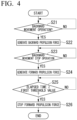
- FIG. 4 is a flowchart for describing an example of a process executed by the watercraft control device 11C of the first embodiment when the operation unit 11B receives an input operation for moving the watercraft 11 backward and then receives an input operation for stopping the backward movement of the watercraft 11.
- step S21 the watercraft control device 11C determines whether or not the operation unit 11B has received the input operation for moving the watercraft 11 backward.
- step S21 is iteratively executed.
- the process proceeds to step S22.
- step S22 the watercraft control device 11C operates the actuator 11A so that the propulsion force generation unit 11A2 of the actuator 11A generates a propulsion force for moving the watercraft 11 backward. As a result, the watercraft 11 moves backward.
- step S23 the watercraft control device 11C determines whether or not the operation unit 11B has received the input operation for stopping the backward movement of the watercraft 11.
- step S23 is iteratively executed.
- the process proceeds to step S24.
- step S24 the watercraft control device 11C causes the actuator 11A to stop the generation of the propulsion force for moving the watercraft 11 backward.
- an inertial force headway
- the watercraft control device 11C operates the actuator 11A so that the actuator 11A generates a propulsion force in an opposite direction (a forward direction of the watercraft 11) to a direction of the inertial force occurring in the watercraft 11 (a backward direction of the watercraft 11).
- step S24 the watercraft control device 11C causes the actuator 11A to generate a forward propulsion force of the watercraft 11 without any need for the operation unit 11B to receive an input operation for causing the actuator 11A to generate the forward propulsion force of the watercraft 11.
- the watercraft control device 11C causes the actuator 11A to generate a forward propulsion force of the watercraft 11 without any need for the operation unit 11B to receive an input operation for causing the actuator 11A to generate the forward propulsion force of the watercraft 11.
- step S25 the watercraft control device 11C monitors an elapsed time from the time when the operation unit 11B receives the input operation for stopping the operation of the actuator 11A (i.e., the time when it is determined that the operation unit 11B has received the input operation for stopping the backward movement of the watercraft 11 in step S23). Specifically, in step S25, the watercraft control device 11C determines whether or not the elapsed time from the time when the operation unit 11B receives the input operation for stopping the operation of the actuator 11A is greater than or equal to the first threshold value.
- step S25 is iteratively executed.
- the process proceeds to step S26.
- step S26 the watercraft control device 11C causes the actuator 11A to stop the generation of the propulsion force in the forward direction of the watercraft 11.
- the watercraft control device 11C operates the actuator 11A without any need for the operation unit 11B to receive the input operation so that the actuator 11A generates the propulsion force in an opposite direction (the forward direction of the watercraft 11) to a direction of the inertial force occurring in the watercraft 11 (the backward direction of the watercraft 11).
- the watercraft control device 11C sets a period in which the actuator 11A is operated so that the actuator 11A generates the propulsion force in the opposite direction (the forward direction of the watercraft 11) to the direction of the inertial force occurring in the watercraft 11 (the backward direction of the watercraft 11) on the basis of the elapsed time from the time when the operation unit 11B receives the input operation for stopping the operation of the actuator 11A (the time when YES is determined in step S23 of FIG 3 ).
- the watercraft control device 11C when the operation unit 11B has received the input operation for stopping the operation of the actuator 11A (when YES is determined in step S23 of FIG 3 ) while the watercraft control device 11C is operating the actuator 11A, the watercraft control device 11C operates the actuator 11A without any need for the operation unit 11B to receive the input operation so that the actuator 11A generates the propulsion force in the opposite direction (the forward direction of the watercraft 11) to the direction of the inertial force occurring in the watercraft 11 (the backward direction of the watercraft 11).
- the watercraft operator's input operation for counteracting the inertial force occurring in the watercraft 11 during the transition from the operating state of the actuator 11A to the stopped state of the actuator 11A can be eliminated.
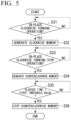
- FIG. 5 is a flowchart for describing an example of a process executed by the watercraft control device 11C of the first embodiment when the operation unit 11B receives an input operation for turning the watercraft 11 clockwise in place and then receives an input operation for stopping the in-place clockwise turning of the watercraft 11.
- step S31 the watercraft control device 11C determines whether or not the operation unit 11B has received the input operation for turning the watercraft 11 clockwise in place.
- step S31 is iteratively executed.
- the process proceeds to step S32.
- step S32 the watercraft control device 11C operates the actuator 11A so that the actuator 11A causes the watercraft 11 to generate a moment for turning the watercraft 11 clockwise in place. As a result, the watercraft 11 turns clockwise in place.
- step S33 the watercraft control device 11C determines whether or not the operation unit 11B has received an input operation for stopping the in-place clockwise turning of the watercraft 11.
- step S33 is iteratively executed.
- the process proceeds to step S34.
- step S34 the watercraft control device 11C causes the actuator 11A to stop the generation of a moment for turning the watercraft 11 clockwise in place. As a result, a moment of inertia for trying to continue the in-place clockwise turning occurs. Therefore, in the example shown in FIG. 5 , in step S34, the watercraft control device 11C operates the actuator 11A so that the actuator 11A causes the watercraft 11 to generate the moment in the opposite direction (counterclockwise) to the direction (clockwise) of the moment of inertia occurring in the watercraft 11.
- step S34 the watercraft control device 11C causes the watercraft 11 to generate a counterclockwise moment without any need for the operation unit 11B to receive an input operation for causing the watercraft 11 to generate a counterclockwise moment.
- the watercraft control device 11C causes the watercraft 11 to generate a counterclockwise moment without any need for the operation unit 11B to receive an input operation for causing the watercraft 11 to generate a counterclockwise moment.
- step S35 the watercraft control device 11C monitors an elapsed time from the time when the operation unit 11B receives the input operation for stopping the operation of the actuator 11A (i.e., the time when it is determined that the operation unit 11B has received the input operation for stopping the in-place clockwise turning of the watercraft 11 in step S33). Specifically, in step S35, the watercraft control device 11C determines whether or not the elapsed time from the time when the operation unit 11B receives the input operation for stopping the operation of the actuator 11A is greater than or equal to a first threshold value.
- step S35 is iteratively executed.
- the process proceeds to step S36.
- step S36 the watercraft control device 11C causes the actuator 11A to stop the generation of the counterclockwise moment.
- the watercraft control device 11C operates the actuator 11A without any need for the operation unit 11B to receive the input operation so that the actuator 11A causes the watercraft 11 to generate the moment in the opposite direction (counterclockwise) to the direction (clockwise) of the moment of inertia occurring in the watercraft 11.
- the watercraft control device 11C sets a period in which the actuator 11A is operated so that the actuator 11A causes the watercraft 11 to generate the moment in the opposite direction (counterclockwise) to the direction (clockwise) of the moment of inertia occurring in the watercraft 11 on the basis of the elapsed time from the time when the operation unit 11B receives the input operation for stopping the operation of the actuator 11A (the time when YES is determined in step S33).
- the watercraft control device 11C when the operation unit 11B has received the input operation for stopping the operation of the actuator 11A while the watercraft control device 11C is operating the actuator 11A (when YES is determined in step S33), the watercraft control device 11C operates the actuator 11A without any need for the operation unit 11B to receive the input operation so that the actuator 11A causes the watercraft 11 to generate the moment in the opposite direction (counterclockwise) to the direction (clockwise) of the moment of inertia occurring in the watercraft 11.
- the watercraft operator's input operation for counteracting the moment of inertia occurring in the watercraft 11 during the transition from the operating state of the actuator 11A to the stopped state of the actuator 11A can be eliminated.
- FIG. 6 is a flowchart for describing an example of a process executed by the watercraft control device 11C of the first embodiment when the operation unit 11B receives an input operation for turning the watercraft 11 counterclockwise in place and then receives an input operation for stopping the in-place counterclockwise turning of the watercraft 11.
- step S41 the watercraft control device 11C determines whether or not the operation unit 11B has received the input operation for turning the watercraft 11 counterclockwise in place.
- step S41 is iteratively executed.
- the process proceeds to step S42.
- step S42 the watercraft control device 11C operates the actuator 11A so that the actuator 11A causes the watercraft 11 to generate a moment for turning the watercraft 11 counterclockwise in place. As a result, the watercraft 11 turns counterclockwise in place.
- step S43 the watercraft control device 11C determines whether or not the operation unit 11B has received an input operation for stopping the in-place counterclockwise turning of the watercraft 11.
- step S43 is iteratively executed.
- the process proceeds to step S44.
- step S44 the watercraft control device 11C causes the actuator 11A to stop the generation of a moment for turning the watercraft 11 counterclockwise in place. As a result, a moment of inertia for trying to continue the in-place counterclockwise turning occurs. Therefore, in the example shown in FIG. 6 , in step S44, the watercraft control device 11C operates the actuator 11A so that the actuator 11A causes the watercraft 11 to generate the moment in the opposite direction (clockwise) to the direction (counterclockwise) of the moment of inertia occurring in the watercraft 11.
- step S44 the watercraft control device 11C causes the watercraft 11 to generate a clockwise moment without any need for the operation unit 11B to receive an input operation for causing the watercraft 11 to generate a clockwise moment.
- the watercraft control device 11C causes the watercraft 11 to generate a clockwise moment without any need for the operation unit 11B to receive an input operation for causing the watercraft 11 to generate a clockwise moment.
- step S45 the watercraft control device 11C monitors an elapsed time from the time when the operation unit 11B receives the input operation for stopping the operation of the actuator 11A (i.e., the time when it is determined that the operation unit 11B has received the input operation for stopping the in-place counterclockwise turning of the watercraft 11 in step S43). Specifically, in step S45, the watercraft control device 11C determines whether or not the elapsed time from the time when the operation unit 11B receives the input operation for stopping the operation of the actuator 11A is greater than or equal to a first threshold value.
- step S45 is iteratively executed.
- the process proceeds to step S46.
- step S46 the watercraft control device 11C causes the actuator 11A to stop the generation of the clockwise moment.
- the watercraft control device 11C operates the actuator 11A without any need for the operation unit 11B to receive the input operation so that the actuator 11A causes the watercraft 11 to generate the moment in the opposite direction (clockwise) to the direction (counterclockwise) of the moment of inertia occurring in the watercraft 11.
- the watercraft control device 11C sets a period in which the actuator 11A is operated so that the actuator 11A causes the watercraft 11 to generate the moment in the opposite direction (clockwise) to the direction (counterclockwise) of the moment of inertia occurring in the watercraft 11 on the basis of the elapsed time from the time when the operation unit 11B receives the input operation for stopping the operation of the actuator 11A (the time when YES is determined in step S43).
- the watercraft control device 11C when the operation unit 11B has received the input operation for stopping the operation of the actuator 11A while the watercraft control device 11C is operating the actuator 11A (when YES is determined in step S43), the watercraft control device 11C operates the actuator 11A without any need for the operation unit 11B to receive the input operation so that the actuator 11A causes the watercraft 11 to generate the moment in the opposite direction (clockwise) to the direction (counterclockwise) of the moment of inertia occurring in the watercraft 11.
- the watercraft operator's input operation for counteracting the moment of inertia occurring in the watercraft 11 during the transition from the operating state of the actuator 11A to the stopped state of the actuator 11A can be eliminated.
- FIG. 7 is a flowchart for describing an example of a process executed by the watercraft control device 11C of the first embodiment when the operation unit 11B receives an input operation for moving the watercraft 11 forward and turning the watercraft 11 clockwise and then receives an input operation for stopping the forward movement and clockwise turning of the watercraft 11.
- step S51 the watercraft control device 11C determines whether or not the operation unit 11B has received the input operation for moving the watercraft 11 forward and turning the watercraft 11 clockwise.
- step S51 is iteratively executed.
- the process proceeds to step S52.
- step S52 the watercraft control device 11C operates the actuator 11A so that the actuator 11A generates a propulsion force for moving the watercraft 11 forward and causes the watercraft 11 to generate a moment for turning the watercraft 11 clockwise. As a result, the watercraft 11 moves forward and turns clockwise.
- step S53 the watercraft control device 11C determines whether or not the operation unit 11B has received the input operation for stopping the forward movement and clockwise turning of the watercraft 11.
- step S53 is iteratively executed.
- the process proceeds to step S54.
- step S54 the watercraft control device 11C causes the actuator 11A to stop the generation of a propulsion force for moving the watercraft 11 forward and the generation of a moment for turning the watercraft 11 clockwise.
- an inertial force for trying to continue the forward movement and a moment of inertia for trying to continue the clockwise turning occur. Therefore, in the example shown in FIG.
- step S54 the watercraft control device 11C operates the actuator 11A so that the actuator 11A generates a propulsion force in an opposite direction (a backward direction of the watercraft 11) to a direction of the inertial force occurring in the watercraft 11 (a forward direction of the watercraft 11) and causes the watercraft 11 to generate the moment in the opposite direction (counterclockwise) to the direction (clockwise) of the moment of inertia occurring in the watercraft 11.
- step S54 the watercraft control device 11C causes the actuator 11A to generate a backward propulsion force of the watercraft 11 and causes the watercraft 11 to generate a counterclockwise moment without any need for the operation unit 11B to receive an input operation for causing the actuator 11A to generate the backward propulsion force of the watercraft 11 and causing the watercraft 11 to generate a counterclockwise moment.
- the watercraft control device 11C causes the actuator 11A to generate a backward propulsion force of the watercraft 11 and causes the watercraft 11 to generate a counterclockwise moment without any need for the operation unit 11B to receive an input operation for causing the actuator 11A to generate the backward propulsion force of the watercraft 11 and causing the watercraft 11 to generate a counterclockwise moment.
- step S55 the watercraft control device 11C monitors an elapsed time from the time when the operation unit 11B has received the input operation for stopping the operation of the actuator 11A (i.e., the time when it is determined that the operation unit 11B has received the input operation for stopping the forward movement and clockwise turning of the watercraft 11 in step S53). Specifically, in step S55, the watercraft control device 11C determines whether or not the elapsed time from the time when the operation unit 11B receives the input operation for stopping the operation of the actuator 11A is greater than or equal to the first threshold value.
- step S55 is iteratively executed.
- the process proceeds to step S56.
- step S56 the watercraft control device 11C causes the actuator 11A to stop the generation of the backward propulsion force of the watercraft 11 and the generation of the counterclockwise moment.
- the watercraft control device 11C operates the actuator 11A without any need for the operation unit 11B to receive the input operation so that the actuator 11A generates the propulsion force in an opposite direction (the backward direction of the watercraft 11) to a direction of the inertial force occurring in the watercraft 11 (the forward direction of the watercraft 11) and causes the watercraft 11 to generate the moment in the opposite direction (counterclockwise) to the direction (clockwise) of the moment of inertia occurring in the watercraft 11.
- the watercraft control device 11C sets a period in which the actuator 11A is operated so that the actuator 11A generates the propulsion force in the opposite direction (the backward direction of the watercraft 11) to the direction of the inertial force occurring in the watercraft 11 (the forward direction of the watercraft 11) and causes the watercraft 11 to generate the moment in the opposite direction (counterclockwise) to the direction (clockwise) of the moment of inertia occurring in the watercraft 11 on the basis of the elapsed time from the time when the operation unit 11B receives the input operation for stopping the operation of the actuator 11A (the time when YES is determined in step S53).
- the watercraft control device 11C when the operation unit 11B has received the input operation for stopping the operation of the actuator 11A (when YES is determined in step S53) while the watercraft control device 11C is operating the actuator 11A, the watercraft control device 11C operates the actuator 11A without any need for the operation unit 11B to receive the input operation so that the actuator 11A generates the propulsion force in the opposite direction (the backward direction of the watercraft 11) to the direction of the inertial force occurring in the watercraft 11 (the forward direction of the watercraft 11) and causes the watercraft 11 to generate the moment in the opposite direction (counterclockwise) to the direction (clockwise) of the moment of inertia occurring in the watercraft 11.
- the watercraft operator's input operation for counteracting the moment of inertia occurring in the watercraft 11 during the transition from the operating state of the actuator 11A to the stopped state of the actuator 11A can be eliminated.
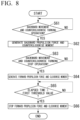
- FIG. 8 is a flowchart for describing an example of a process executed by the watercraft control device 11C of the first embodiment when the operation unit 11B receives an input operation for moving the watercraft 11 backward and turning the watercraft 11 counterclockwise and then receives an input operation for stopping the backward movement and counterclockwise turning of the watercraft 11.
- step S61 the watercraft control device 11C determines whether or not the operation unit 11B has received the input operation for moving the watercraft 11 backward and turning the watercraft 11 counterclockwise.
- step S61 is iteratively executed.
- the process proceeds to step S62.
- step S62 the watercraft control device 11C operates the actuator 11A so that the actuator 11A generates a propulsion force for moving the watercraft 11 backward and causes the watercraft 11 to generate a moment for turning the watercraft 11 counterclockwise. As a result, the watercraft 11 moves backward and turns counterclockwise.
- step S63 the watercraft control device 11C determines whether or not the operation unit 11B has received the input operation for stopping the backward movement and counterclockwise turning of the watercraft 11.
- step S63 is iteratively executed.
- the process proceeds to step S64.
- step S64 the watercraft control device 11C causes the actuator 11A to stop the generation of a propulsion force for moving the watercraft 11 backward and the generation of a moment for turning the watercraft 11 counterclockwise.
- an inertial force for trying to continue the backward movement and a moment of inertia for trying to continue the counterclockwise turning occur. Therefore, in the example shown in FIG.
- step S64 the watercraft control device 11C operates the actuator 11A so that the actuator 11A generates a propulsion force in an opposite direction (the forward direction of the watercraft 11) to a direction of the inertial force occurring in the watercraft 11 (the backward direction of the watercraft 11) and causes the watercraft 11 to generate the moment in the opposite direction (clockwise) to the direction (counterclockwise) of the moment of inertia occurring in the watercraft 11.
- step S64 the watercraft control device 11C causes the actuator 11A to generate a forward propulsion force of the watercraft 11 and causes the watercraft 11 to generate a clockwise moment without any need for the operation unit 11B to receive an input operation for causing the actuator 11A to generate the forward propulsion force of the watercraft 11 and causing the watercraft 11 to generate the clockwise moment.
- the watercraft control device 11C causes the actuator 11A to generate a forward propulsion force of the watercraft 11 and causes the watercraft 11 to generate a clockwise moment without any need for the operation unit 11B to receive an input operation for causing the actuator 11A to generate the forward propulsion force of the watercraft 11 and causing the watercraft 11 to generate the clockwise moment.
- step S65 the watercraft control device 11C monitors an elapsed time from the time when the operation unit 11B has received the input operation for stopping the operation of the actuator 11A (i.e., the time when it is determined that the operation unit 11B has received the input operation for stopping the backward movement and counterclockwise turning of the watercraft 11 in step S63). Specifically, in step S65, the watercraft control device 11C determines whether or not the elapsed time from the time when the operation unit 11B receives the input operation for stopping the operation of the actuator 11A is greater than or equal to the first threshold value.
- step S65 is iteratively executed.
- the process proceeds to step S66.
- step S66 the watercraft control device 11C causes the actuator 11A to stop the generation of the forward propulsion force of the watercraft 11 and the generation of the clockwise moment.
- the watercraft control device 11C operates the actuator 11A without any need for the operation unit 11B to receive the input operation so that the actuator 11A generates the propulsion force in an opposite direction (the forward direction of the watercraft 11) to a direction of the inertial force occurring in the watercraft 11 (the backward direction of the watercraft 11) and causes the watercraft 11 to generate the moment in the opposite direction (clockwise) to the direction (counterclockwise) of the moment of inertia occurring in the watercraft 11.
- the watercraft control device 11C sets a period in which the actuator 11A is operated so that the actuator 11A generates the propulsion force in the opposite direction (the forward direction of the watercraft 11) to the direction of the inertial force occurring in the watercraft 11 (the backward direction of the watercraft 11) and causes the watercraft 11 to generate the moment in the opposite direction (clockwise) to the direction (counterclockwise) of the moment of inertia occurring in the watercraft 11 on the basis of the elapsed time from the time when the operation unit 11B receives the input operation for stopping the operation of the actuator 11A (the time when YES is determined in step S63).
- the watercraft control device 11C when the operation unit 11B has received the input operation for stopping the operation of the actuator 11A (when YES is determined in step S63) while the watercraft control device 11C is operating the actuator 11A, the watercraft control device 11C operates the actuator 11A without any need for the operation unit 11B to receive the input operation so that the actuator 11A generates the propulsion force in the opposite direction (the forward direction of the watercraft 11) to the direction of the inertial force occurring in the watercraft 11 (the backward direction of the watercraft 11) and causes the watercraft 11 to generate the moment in the opposite direction (clockwise) to the direction (counterclockwise) of the moment of inertia occurring in the watercraft 11.
- the watercraft operator's input operation for counteracting the moment of inertia occurring in the watercraft 11 during the transition from the operating state of the actuator 11A to the stopped state of the actuator 11A can be eliminated.
- a watercraft maneuvering system 1 of the second embodiment is configured like the watercraft maneuvering system 1 of the first embodiment described above, except for matters to be described below. Therefore, according to the watercraft maneuvering system 1 of the second embodiment, effects similar to those of the watercraft maneuvering system 1 of the first embodiment described above can be achieved, except for the matters to be described below.
- the watercraft maneuvering system 1 including a watercraft 11 to which a watercraft control device 11C of the second embodiment is applied is configured like the watercraft maneuvering system 1 of the first embodiment shown in FIG. 1 .
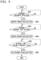
- FIG. 9 is a flowchart for describing an example of a process executed by the watercraft control device 11C of the second embodiment when an operation unit 11B receives an input operation for moving the watercraft 11 forward and then receives an input operation for stopping the forward movement of the watercraft 11.
- step SA1 the watercraft control device 11C determines whether or not the operation unit 11B has received an input operation for moving the watercraft 11 forward.
- step SA1 is iteratively executed.
- the process proceeds to step SA2.
- step SA2 the watercraft control device 11C operates an actuator 11A so that a propulsion force generation unit 11A2 of the actuator 11A generates a propulsion force for moving the watercraft 11 forward. As a result, the watercraft 11 moves forward.
- step SA3 the watercraft control device 11C determines whether or not the operation unit 11B has received an input operation for stopping the forward movement of the watercraft 11.
- step SA3 is iteratively executed.
- the process proceeds to step SA4.
- step SA4 the watercraft control device 11C causes the actuator 11A to stop the generation of the propulsion force for moving the watercraft 11 forward.
- an inertial force headway
- the watercraft control device 11C operates the actuator 11A so that the actuator 11A generates the propulsion force in an opposite direction (a backward direction of the watercraft 11) to a direction of the inertial force occurring in the watercraft 11 (a forward direction of the watercraft 11).
- step SA4 the watercraft control device 11C causes the actuator 11A to generate a backward propulsion force of the watercraft 11 without any need for the operation unit 11B to receive an input operation for causing the actuator 11A to generate the backward propulsion force of the watercraft 11.
- the watercraft control device 11C causes the actuator 11A to generate a backward propulsion force of the watercraft 11 without any need for the operation unit 11B to receive an input operation for causing the actuator 11A to generate the backward propulsion force of the watercraft 11.
- step SA5 the watercraft control device 11C monitors a speed of the watercraft 11. Specifically, in step SA5, the watercraft control device 11C determines whether or not the speed of the watercraft 11 detected by a watercraft speed detection unit 11E has decreased to a second threshold value or less. When the speed of the watercraft 11 has not decreased to the second threshold value or less (i.e., when the watercraft 11 continuously moves forward due to the inertial force (headway) of the watercraft 11), step SA5 is iteratively executed.
- step SA6 when the speed of the watercraft 11 has decreased to the second threshold value or less (i.e., when it can be estimated that the forward movement of the watercraft 11 due to the inertial force (headway) of the watercraft 11 has ended), the process proceeds to step SA6.
- step SA6 the watercraft control device 11C causes the actuator 11A to stop the generation of the backward propulsion force of the watercraft 11.
- the watercraft control device 11C operates the actuator 11A without any need for the operation unit 11B to receive the input operation so that the actuator 11A generates the propulsion force in an opposite direction (the backward direction of the watercraft 11) to a direction of the inertial force occurring in the watercraft 11 (the forward direction of the watercraft 11).
- the watercraft control device 11C sets a period in which the actuator 11A is operated so that the actuator 11A generates the propulsion force in the opposite direction (the backward direction of the watercraft 11) to the direction of the inertial force occurring in the watercraft 11 (the forward direction of the watercraft 11) on the basis of the speed of the watercraft 11.
- the watercraft control device 11C when the operation unit 11B has received the input operation for stopping the operation of the actuator 11A (when YES is determined in step SA3) while the watercraft control device 11C is operating the actuator 11A, the watercraft control device 11C operates the actuator 11A without any need for the operation unit 11B to receive the input operation so that the actuator 11A generates the propulsion force in the opposite direction (the backward direction of the watercraft 11) to the direction of the inertial force occurring in the watercraft 11 (the forward direction of the watercraft 11).
- the watercraft operator's input operation for counteracting the inertial force occurring in the watercraft 11 during the transition from the operating state of the actuator 11A to the stopped state of the actuator 11A can be eliminated.
- FIG. 10 is a flowchart for describing an example of a process executed by the watercraft control device 11C of the second embodiment when the operation unit 11B receives an input operation for moving the watercraft 11 backward and then receives an input operation for stopping the backward movement of the watercraft 11.
- step SB1 the watercraft control device 11C determines whether or not the operation unit 11B has received an input operation for moving the watercraft 11 backward.
- step SB1 is iteratively executed.
- the process proceeds to step SB2.
- step SB2 the watercraft control device 11C operates the actuator 11A so that a propulsion force generation unit 11A2 of the actuator 11A generates a propulsion force for moving the watercraft 11 backward. As a result, the watercraft 11 moves backward.
- step SB3 the watercraft control device 11C determines whether or not the operation unit 11B has received an input operation for stopping the backward movement of the watercraft 11.
- step SB3 is iteratively executed.
- the process proceeds to step SB4.
- step SB4 the watercraft control device 11C causes the actuator 11A to stop the generation of the propulsion force for moving the watercraft 11 backward.
- an inertial force headway
- the watercraft control device 11C operates the actuator 11A so that the actuator 11A generates the propulsion force in an opposite direction (a forward direction of the watercraft 11) to a direction of the inertial force occurring in the watercraft 11 (a backward direction of the watercraft 11).
- step SB4 the watercraft control device 11C causes the actuator 11A to generate a forward propulsion force of the watercraft 11 without any need for the operation unit 11B to receive an input operation for causing the actuator 11A to generate the forward propulsion force of the watercraft 11.
- the watercraft control device 11C causes the actuator 11A to generate a forward propulsion force of the watercraft 11 without any need for the operation unit 11B to receive an input operation for causing the actuator 11A to generate the forward propulsion force of the watercraft 11.
- step SB5 the watercraft control device 11C monitors a speed of the watercraft 11. Specifically, in step SB5, the watercraft control device 11C determines whether or not the speed of the watercraft 11 detected by the watercraft speed detection unit 11E has decreased to a second threshold value or less. When the speed of the watercraft 11 has not decreased to the second threshold value or less (i.e., when the watercraft 11 continuously moves backward due to the inertial force (headway) of the watercraft 11), step SB5 is iteratively executed.
- step SB6 when the speed of the watercraft 11 has decreased to the second threshold value or less (i.e., when it can be estimated that the backward movement of the watercraft 11 due to the inertial force (headway) of the watercraft 11 has ended), the process proceeds to step SB6.
- step SB6 the watercraft control device 11C causes the actuator 11A to stop the generation of the forward propulsion force of the watercraft 11.
- the watercraft control device 11C operates the actuator 11A without any need for the operation unit 11B to receive the input operation so that the actuator 11A generates the propulsion force in an opposite direction (the forward direction of the watercraft 11) to a direction of the inertial force occurring in the watercraft 11 (the backward direction of the watercraft 11).
- the watercraft control device 11C sets a period in which the actuator 11A is operated so that the actuator 11A generates the propulsion force in the opposite direction (the forward direction of the watercraft 11) to the direction of the inertial force occurring in the watercraft 11 (the backward direction of the watercraft 11) on the basis of the speed of the watercraft 11.
- the watercraft control device 11C when the operation unit 11B has received the input operation for stopping the operation of the actuator 11A (when YES is determined in step SB3) while the watercraft control device 11C is operating the actuator 11A, the watercraft control device 11C operates the actuator 11A without any need for the operation unit 11B to receive the input operation so that the actuator 11A generates the propulsion force in the opposite direction (the forward direction of the watercraft 11) to the direction of the inertial force occurring in the watercraft 11 (the backward direction of the watercraft 11).
- the watercraft operator's input operation for counteracting the inertial force occurring in the watercraft 11 during the transition from the operating state of the actuator 11A to the stopped state of the actuator 11A can be eliminated.
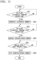
- FIG. 11 is a flowchart for describing an example of a process executed by the watercraft control device 11C of the second embodiment when the operation unit 11B receives an input operation for turning the watercraft 11 clockwise in place and then receives an input operation for stopping the in-place clockwise turning of the watercraft 11.
- step SC1 the watercraft control device 11C determines whether or not the operation unit 11B has received an input operation for turning the watercraft 11 clockwise in place.
- step SC1 is iteratively executed.
- the process proceeds to step SC2.
- step SC2 the watercraft control device 11C operates the actuator 11A so that the actuator 11A causes the watercraft 11 to generate a moment for turning the watercraft 11 clockwise in place. As a result, the watercraft 11 turns clockwise in place.
- step SC3 the watercraft control device 11C determines whether or not the operation unit 11B has received an input operation for stopping the in-place clockwise turning of the watercraft 11.
- step SC3 is iteratively executed.
- the process proceeds to step SC4.
- step SC4 the watercraft control device 11C causes the actuator 11A to stop the generation of a moment for turning the watercraft 11 clockwise in place. As a result, a moment of inertia for trying to continue the in-place clockwise turning occurs. Therefore, in the example shown in FIG. 11 , in step SC4, the watercraft control device 11C operates the actuator 11A so that the actuator 11A causes the watercraft 11 to generate the moment in the opposite direction (counterclockwise) to the direction (clockwise) of the moment of inertia occurring in the watercraft 11.
- step SC4 the watercraft control device 11C causes the watercraft 11 to generate a counterclockwise moment without any need for the operation unit 11B to receive an input operation for causing the watercraft 11 to generate a counterclockwise moment.
- the watercraft control device 11C causes the watercraft 11 to generate a counterclockwise moment without any need for the operation unit 11B to receive an input operation for causing the watercraft 11 to generate a counterclockwise moment.
- step SC5 the watercraft control device 11C monitors an angular speed of the watercraft 11. Specifically, in step SC5, the watercraft control device 11C determines whether or not the angular speed of the watercraft 11 calculated on the basis of a bow azimuth detected by the bow azimuth detection unit 11D has decreased to a third threshold value or less. When the angular speed of the watercraft 11 has not decreased to the third threshold value or less (i.e., when the in-place clockwise turning of the watercraft 11 due to the moment of inertia of the watercraft 11 continues), step SC5 is iteratively executed.
- step SC6 when the angular speed of the watercraft 11 has decreased to the third threshold value or less (i.e., when it can be estimated that the in-place clockwise turning of the watercraft 11 due to the moment of inertia of the watercraft 11 has ended), the process proceeds to step SC6.
- step SC6 the watercraft control device 11C causes the actuator 11A to stop the generation of the counterclockwise moment.
- the watercraft control device 11C operates the actuator 11A without any need for the operation unit 11B to receive the input operation so that the actuator 11A causes the watercraft 11 to generate the moment in the opposite direction (counterclockwise) to the direction (clockwise) of the moment of inertia occurring in the watercraft 11.
- the watercraft control device 11C sets a period in which the actuator 11A is operated so that the actuator 11A causes the watercraft 11 to generate the moment in the opposite direction (counterclockwise) to the direction (clockwise) of the moment of inertia occurring in the watercraft 11 on the basis of an angular speed of the watercraft 11.
- the watercraft control device 11C when the operation unit 11B has received the input operation for stopping the operation of the actuator 11A while the watercraft control device 11C is operating the actuator 11A (when YES is determined in step SC3), the watercraft control device 11C operates the actuator 11A without any need for the operation unit 11B to receive the input operation so that the actuator 11A causes the watercraft 11 to generate the moment in the opposite direction (counterclockwise) to the direction (clockwise) of the moment of inertia occurring in the watercraft 11.
- the watercraft operator's input operation for counteracting the moment of inertia occurring in the watercraft 11 during the transition from the operating state of the actuator 11A to the stopped state of the actuator 11A can be eliminated.
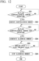
- FIG. 12 is a flowchart for describing an example of a process executed by the watercraft control device 11C of the second embodiment when the operation unit 11B receives an input operation for turning the watercraft 11 counterclockwise in place and then receives an input operation for stopping the in-place counterclockwise turning of the watercraft 11.
- step SD1 the watercraft control device 11C determines whether or not the operation unit 11B has received the input operation for turning the watercraft 11 counterclockwise in place.
- step SD1 is iteratively executed.
- the process proceeds to step SD2.
- step SD2 the watercraft control device 11C operates the actuator 11A so that the actuator 11A causes the watercraft 11 to generate a moment for turning the watercraft 11 counterclockwise in place. As a result, the watercraft 11 turns counterclockwise in place.
- step SD3 the watercraft control device 11C determines whether or not the operation unit 11B has received an input operation for stopping the in-place counterclockwise turning of the watercraft 11.
- step SD3 is iteratively executed.
- the process proceeds to step SD4.
- step SD4 the watercraft control device 11C causes the actuator 11A to stop the generation of a moment for turning the watercraft 11 counterclockwise in place. As a result, a moment of inertia for trying to continue the in-place counterclockwise turning occurs. Therefore, in the example shown in FIG. 12 , in step SD4, the watercraft control device 11C operates the actuator 11A so that the actuator 11A causes the watercraft 11 to generate the moment in the opposite direction (clockwise) to the direction (counterclockwise) of the moment of inertia occurring in the watercraft 11.
- step SD4 the watercraft control device 11C causes the watercraft 11 to generate a clockwise moment without any need for the operation unit 11B to receive an input operation of causing the watercraft 11 to generate a clockwise moment.
- the watercraft control device 11C causes the watercraft 11 to generate a clockwise moment without any need for the operation unit 11B to receive an input operation of causing the watercraft 11 to generate a clockwise moment.
- step SD5 the watercraft control device 11C monitors an angular speed of the watercraft 11. Specifically, in step SD5, the watercraft control device 11C determines whether or not the angular speed of the watercraft 11 calculated on the basis of a bow azimuth detected by the bow azimuth detection unit 11D has decreased to the third threshold value or less. When the angular speed of the watercraft 11 has not decreased to the third threshold value or less (i.e., when the in-place counterclockwise turning of the watercraft 11 due to the moment of inertia of the watercraft 11 continues), step SD5 is iteratively executed.
- step SD6 when the angular speed of the watercraft 11 has decreased to the third threshold value or less (i.e., when it can be estimated that the in-place counterclockwise turning of the watercraft 11 due to the moment of inertia of the watercraft 11 has ended), the process proceeds to step SD6.
- step SD6 the watercraft control device 11C causes the actuator 11A to stop the generation of the clockwise moment.
- the watercraft control device 11C operates the actuator 11A without any need for the operation unit 11B to receive the input operation so that the actuator 11A causes the watercraft 11 to generate the moment in the opposite direction (clockwise) to the direction (counterclockwise) of the moment of inertia occurring in the watercraft 11.
- the watercraft control device 11C sets a period in which the actuator 11A is operated so that the actuator 11A causes the watercraft 11 to generate the moment in the opposite direction (clockwise) to the direction (counterclockwise) of the moment of inertia occurring in the watercraft 11 on the basis of an angular speed of the watercraft 11.
- the watercraft control device 11C when the operation unit 11B has received the input operation for stopping the operation of the actuator 11A while the watercraft control device 11C is operating the actuator 11A (when YES is determined in step SD3), the watercraft control device 11C operates the actuator 11A without any need for the operation unit 11B to receive the input operation so that the actuator 11A causes the watercraft 11 to generate the moment in the opposite direction (clockwise) to the direction (counterclockwise) of the moment of inertia occurring in the watercraft 11.
- the watercraft operator's input operation for counteracting the moment of inertia occurring in the watercraft 11 during the transition from the operating state of the actuator 11A to the stopped state of the actuator 11A can be eliminated.
- FIG. 13 is a flowchart for describing an example of a process executed by the watercraft control device 11C of the second embodiment when the operation unit 11B receives an input operation for moving the watercraft 11 forward and turning the watercraft 11 clockwise and then receives an input operation for stopping the forward movement and clockwise turning of the watercraft 11.
- step SE1 the watercraft control device 11C determines whether or not the operation unit 11B has received the input operation for moving the watercraft 11 forward and turning the watercraft 11 clockwise.
- step SE1 is iteratively executed.
- the process proceeds to step SE2.
- step SE2 the watercraft control device 11C operates the actuator 11A so that the actuator 11A generates a propulsion force for moving the watercraft 11 forward and causes the watercraft 11 to generate a moment for turning the watercraft 11 clockwise. As a result, the watercraft 11 moves forward and turns clockwise.
- step SE3 the watercraft control device 11C determines whether or not the operation unit 11B has received the input operation for stopping the forward movement and clockwise turning of the watercraft 11.
- step SE3 is iteratively executed.
- the process proceeds to step SE4.
- step SE4 the watercraft control device 11C causes the actuator 11A to stop the generation of a propulsion force for moving the watercraft 11 forward and the generation of a moment for turning the watercraft 11 clockwise.
- an inertial force for trying to continue the forward movement and a moment of inertia for trying to continue the clockwise turning occur. Therefore, in the example shown in FIG.
- step SE4 the watercraft control device 11C operates the actuator 11A so that the actuator 11A generates a propulsion force in an opposite direction (a backward direction of the watercraft 11) to a direction of the inertial force occurring in the watercraft 11 (a forward direction of the watercraft 11) and causes the watercraft 11 to generate the moment in the opposite direction (counterclockwise) to the direction (clockwise) of the moment of inertia occurring in the watercraft 11.
- step SE4 the watercraft control device 11C causes the actuator 11A to generate a backward propulsion force of the watercraft 11 and causes the watercraft 11 to generate a counterclockwise moment without any need for the operation unit 11B to receive an input operation for causing the actuator 11A to generate the backward propulsion force of the watercraft 11 and causing the watercraft 11 to generate a counterclockwise moment.
- the watercraft control device 11C causes the actuator 11A to generate a backward propulsion force of the watercraft 11 and causes the watercraft 11 to generate a counterclockwise moment without any need for the operation unit 11B to receive an input operation for causing the actuator 11A to generate the backward propulsion force of the watercraft 11 and causing the watercraft 11 to generate a counterclockwise moment.
- step SE5 the watercraft control device 11C monitors a speed of the watercraft 11. Specifically, in step SE5, the watercraft control device 11C determines whether or not the speed of the watercraft 11 detected by the watercraft speed detection unit 11E has decreased to a fourth threshold value or less. When the speed of the watercraft 11 has not decreased to the fourth threshold value or less (i.e., when the watercraft 11 moves forward due to the inertial force of the watercraft 11 and the watercraft 11 continuously turns clockwise due to the moment of inertia of the watercraft 11), step SE5 is iteratively executed.
- step SE6 when the speed of the watercraft 11 has decreased to the fourth threshold value or less (i.e., when it can be estimated that the forward movement of the watercraft 11 due to the inertial force of the watercraft 11 and the clockwise turning of the watercraft 11 due to the moment of inertia of the watercraft 11 has ended), the process proceeds to step SE6.
- step SE6 the watercraft control device 11C causes the actuator 11A to stop the generation of the backward propulsion force of the watercraft 11 and the generation of the counterclockwise moment.
- the watercraft control device 11C operates the actuator 11A without any need for the operation unit 11B to receive the input operation so that the actuator 11A generates the propulsion force in an opposite direction (the backward direction of the watercraft 11) to a direction of the inertial force occurring in the watercraft 11 (the forward direction of the watercraft 11) and causes the watercraft 11 to generate the moment in the opposite direction (counterclockwise) to the direction (clockwise) of the moment of inertia occurring in the watercraft 11.
- the watercraft control device 11C sets a period in which the actuator 11A is operated so that the actuator 11A generates the propulsion force in the opposite direction (the backward direction of the watercraft 11) to the direction of the inertial force occurring in the watercraft 11 (the forward direction of the watercraft 11) and causes the watercraft 11 to generate the moment in the opposite direction (counterclockwise) to the direction (clockwise) of the moment of inertia occurring in the watercraft 11 on the basis of the speed of the watercraft 11.
- the watercraft control device 11C when the operation unit 11B has received the input operation for stopping the operation of the actuator 11A (when YES is determined in step SE3) while the watercraft control device 11C is operating the actuator 11A, the watercraft control device 11C operates the actuator 11A without any need for the operation unit 11B to receive the input operation so that the actuator 11A generates the propulsion force in the opposite direction (the backward direction of the watercraft 11) to the direction of the inertial force occurring in the watercraft 11 (the forward direction of the watercraft 11) and causes the watercraft 11 to generate the moment in the opposite direction (counterclockwise) to the direction (clockwise) of the moment of inertia occurring in the watercraft 11.
- the watercraft operator's input operation for counteracting the inertial force and the moment of inertia occurring in the watercraft 11 during the transition from the operating state of the actuator 11A to the stopped state of the actuator 11A can be eliminated.
- FIG. 14 is a flowchart for describing an example of a process executed by the watercraft control device 11C of the second embodiment when the operation unit 11B receives an input operation for moving the watercraft 11 backward and turning the watercraft 11 counterclockwise and then receives an input operation for stopping the backward movement and counterclockwise turning of the watercraft 11.
- step SF1 the watercraft control device 11C determines whether or not the operation unit 11B has received the input operation for moving the watercraft 11 backward and turning the watercraft 11 counterclockwise.
- step SF1 is iteratively executed.
- the process proceeds to step SF2.
- step SF2 the watercraft control device 11C operates the actuator 11A so that the actuator 11A generates a propulsion force for moving the watercraft 11 backward and causes the watercraft 11 to generate a moment for turning the watercraft 11 counterclockwise. As a result, the watercraft 11 moves backward and turns counterclockwise.
- step SF3 the watercraft control device 11C determines whether or not the operation unit 11B has received the input operation for stopping the backward movement and counterclockwise turning of the watercraft 11.
- step SF3 is iteratively executed.
- the process proceeds to step SF4.
- step SF4 the watercraft control device 11C causes the actuator 11A to stop the generation of a propulsion force for moving the watercraft 11 backward and the generation of a moment for turning the watercraft 11 counterclockwise.
- the actuator 11A causes the actuator 11A to stop the generation of a propulsion force for moving the watercraft 11 backward and the generation of a moment for turning the watercraft 11 counterclockwise.
- the watercraft control device 11C operates the actuator 11A so that the actuator 11A generates a propulsion force in an opposite direction (a forward direction of the watercraft 11) to a direction of the inertial force occurring in the watercraft 11 (a backward direction of the watercraft 11) and causes the watercraft 11 to generate the moment in the opposite direction (clockwise) to the direction (counterclockwise) of the moment of inertia occurring in the watercraft 11.
- the watercraft control device 11C causes the actuator 11A to generate a forward propulsion force of the watercraft 11 and causes the watercraft 11 to generate a clockwise moment without any need for the operation unit 11B to receive an input operation for causing the actuator 11A to generate the forward propulsion force of the watercraft 11 and causing the watercraft 11 to generate a clockwise moment.
- the watercraft control device 11C causes the actuator 11A to generate a forward propulsion force of the watercraft 11 and causes the watercraft 11 to generate a clockwise moment without any need for the operation unit 11B to receive an input operation for causing the actuator 11A to generate the forward propulsion force of the watercraft 11 and causing the watercraft 11 to generate a clockwise moment.
- step SF5 the watercraft control device 11C monitors the speed of the watercraft 11. Specifically, in step SF5, the watercraft control device 11C determines whether or not the speed of the watercraft 11 detected by the watercraft speed detection unit 11E has decreased to the fourth threshold value or less. When the speed of the watercraft 11 has not decreased to the fourth threshold value or less (i.e., when the watercraft 11 moves backward due to the inertial force of the watercraft 11 and the watercraft 11 continuously turns counterclockwise due to the moment of inertia of the watercraft 11), step SF5 is iteratively executed.
- step SF6 when the speed of the watercraft 11 has decreased to the fourth threshold value or less (i.e., when it can be estimated that the backward movement of the watercraft 11 due to the inertial force of the watercraft 11 and the counterclockwise turning of the watercraft 11 due to the moment of inertia of the watercraft 11 has ended), the process proceeds to step SF6.
- step SF6 the watercraft control device 11C causes the actuator 11A to stop the generation of the forward propulsion force of the watercraft 11 and the generation of the clockwise moment.
- the watercraft control device 11C operates the actuator 11A without any need for the operation unit 11B to receive the input operation so that the actuator 11A generates the propulsion force in an opposite direction (the forward direction of the watercraft 11) to a direction of the inertial force occurring in the watercraft 11 (the backward direction of the watercraft 11) and causes the watercraft 11 to generate the moment in the opposite direction (clockwise) to the direction (counterclockwise) of the moment of inertia occurring in the watercraft 11.
- the watercraft control device 11C sets a period in which the actuator 11A is operated so that the actuator 11A generates the propulsion force in the opposite direction (the forward direction of the watercraft 11) to the direction of the inertial force occurring in the watercraft 11 (the backward direction of the watercraft 11) and causes the watercraft 11 to generate the moment in the opposite direction (clockwise) to the direction (counterclockwise) of the moment of inertia occurring in the watercraft 11 on the basis of the speed of the watercraft 11.
- the watercraft control device 11C when the operation unit 11B has received the input operation for stopping the operation of the actuator 11A (when YES is determined in step SF3) while the watercraft control device 11C is operating the actuator 11A, the watercraft control device 11C operates the actuator 11A without any need for the operation unit 11B to receive the input operation so that the actuator 11A generates the propulsion force in the opposite direction (the forward direction of the watercraft 11) to the direction of the inertial force occurring in the watercraft 11 (the backward direction of the watercraft 11) and causes the watercraft 11 to generate the moment in the opposite direction (clockwise) to the direction (counterclockwise) of the moment of inertia occurring in the watercraft 11.
- the watercraft operator's input operation for counteracting the inertial force and the moment of inertia occurring in the watercraft 11 during the transition from the operating state of the actuator 11A to the stopped state of the actuator 11A can be eliminated.
- a watercraft maneuvering system 1 of the third embodiment is configured like the watercraft maneuvering system 1 of the first embodiment described above, except for matters to be described below. Therefore, according to the watercraft maneuvering system 1 of the third embodiment, effects similar to those of the watercraft maneuvering system 1 of the first embodiment described above can be achieved, except for the matters to be described below.
- FIG. 15 is a diagram showing an example of the watercraft maneuvering system 1 including a watercraft 11 to which a watercraft control device 11C of the third embodiment is applied.
- the watercraft maneuvering system 1 includes the watercraft 11 and an input device 12.
- the watercraft 11 includes an actuator 11A, an operation unit 11B, the watercraft control device 11C, a bow azimuth detection unit 11D, a watercraft speed detection unit 11E, a watercraft location detection unit 11F, and a communication unit 11G.
- the actuator 11A is configured like the actuator 11A shown in FIG. 1 .
- the operation unit 11B is configured like the operation unit 11B shown in FIG. 1 .
- the watercraft control device 11C is configured like the watercraft control device 11C shown in FIG. 1 .
- the bow azimuth detection unit 11D is configured like the bow azimuth detection unit 11D shown in FIG. 1 .
- the watercraft speed detection unit 11E is configured like the watercraft speed detection unit 11E shown in FIG. 1 .
- the watercraft location detection unit 11F is configured like the watercraft location detection unit 11F shown in FIG. 1 .
- the communication unit 11G communicates with the input device 12.
- the input device 12 is provided separately from the watercraft 11. That is, the input device 12 can be used by a watercraft operator of the watercraft 11, for example, at a location away from the watercraft 11.
- the input device 12 includes an operation unit 12A and a communication unit 12B.
- the operation unit 12A receives an input operation of the watercraft operator of the watercraft 11.
- the communication unit 12B transmits information indicating the input operation of the watercraft operator of the watercraft 11 received by the operation unit 12A to the watercraft 11.
- the communication unit 11G of the watercraft 11 receives information indicating the input operation transmitted by the communication unit 12B of the input device 12.
- the watercraft control device 11C of the watercraft 11 operates the actuator 11A on the basis of the input operation received by the operation unit 12A of the input device 12.
- the watercraft control device 11C determines whether or not the operation unit 12A of the input device 12 has received the input operation for moving the watercraft 11 forward in the step corresponding to step S11 of FIG. 3 .
- the step corresponding to step S11 of FIG. 3 is iteratively executed.
- the process proceeds to the step corresponding to step S12 of FIG. 3 .
- the watercraft control device 11C operates the actuator 11A so that a propulsion force generation unit 11A2 of the actuator 11A generates a propulsion force for moving the watercraft 11 forward.
- the watercraft 11 moves forward (i.e., the watercraft 11 moves in the upward direction of FIG. 2 ).
- the watercraft control device 11C determines whether or not the operation unit 12A of the input device 12 has received an input operation for stopping the forward movement of the watercraft 11.
- the step corresponding to step S13 of FIG. 3 is iteratively executed.
- the process proceeds to the step corresponding to step S14 of FIG. 3 .
- the watercraft control device 11C causes the actuator 11A to stop the generation of the propulsion force for moving the watercraft 11 forward.
- an inertial force (headway) in the upward direction of FIG. 2 for trying to continue forward movement occurs. Therefore, in the watercraft maneuvering system 1 of the third embodiment, in the step corresponding to step S14 of FIG. 3 , the watercraft control device 11C operates the actuator 11A so that the actuator 11A generates a propulsion force in an opposite direction (the downward direction of FIG. 2 ) to a direction of the inertial force occurring in the watercraft 11 (the upward direction of FIG. 2 ). Specifically, in the step corresponding to step S14 of FIG.
- the watercraft control device 11C causes the actuator 11A to generate a propulsion force in the downward direction of FIG. 2 without any need for the operation unit 12A to receive an input operation of causing the actuator 11A to generate the propulsion force in the downward direction of FIG. 2 .
- FIGS. 2(A) and 2(B) it is possible to suppress the movement (headway) of the watercraft 11 in the upward direction of FIG. 2 due to the inertial force occurring in the watercraft 11.
- the watercraft control device 11C monitors an elapsed time from the time when the operation unit 12A of the input device 12 receives the input operation for stopping the operation of the actuator 11A (i.e., the time when it is determined that the operation unit 12A has received the input operation for stopping the forward movement of the watercraft 11 in the step corresponding to step S15 of FIG. 3 ). Specifically, in the step corresponding to step S15 of FIG. 3 , the watercraft control device 11C determines whether or not the elapsed time from the time when the operation unit 12A receives the input operation for stopping the operation of the actuator 11A is greater than or equal to a first threshold value.
- step corresponding to step S15 of FIG. 3 is iteratively executed.
- the process proceeds to the step corresponding to step S16 of FIG. 3 .
- the watercraft control device 11C causes the actuator 11A to stop the generation of the propulsion force in the downward direction of FIG. 2 .
- the watercraft control device 11C when the operation unit 12A of the input device 12 has received the input operation for stopping the generation of the propulsion force for moving the watercraft 11 forward (when YES is determined in the step corresponding to step S13 of FIG. 3 ) while the watercraft control device 11C is operating the actuator 11A, the watercraft control device 11C operates the actuator 11A without any need for the operation unit 12A to receive the input operation so that the actuator 11A generates the propulsion force in an opposite direction (the downward direction of FIG. 2 ) to a direction of the inertial force occurring in the watercraft 11 (the upward direction of FIG. 2 ).
- the watercraft operator's input operation for counteracting the inertial force occurring in the watercraft 11 during the transition from the operating state of the actuator 11A to the stopped state of the actuator 11A can be eliminated.
- the state of the watercraft 11 can appropriately transition from the operating state of the actuator 11A to the stopped state of the actuator 11A.
- the watercraft control device 11C of the third embodiment determines whether or not the operation unit 12A of the input device 12 has received the input operation for turning the watercraft 11 clockwise in place in the step corresponding to step S31 of FIG. 5 .
- the step corresponding to step S31 of FIG. 5 is iteratively executed.
- the process proceeds to the step corresponding to step S32 of FIG. 5 .
- the watercraft control device 11C operates the actuator 11A so that the actuator 11A causes the watercraft 11 to generate a moment for turning the watercraft 11 clockwise in place. As a result, the watercraft 11 turns clockwise in place.
- the watercraft control device 11C determines whether or not the operation unit 12A of the input device 12 has received an input operation for stopping the in-place clockwise turning of the watercraft 11.
- the step corresponding to step S33 of FIG. 5 is iteratively executed.
- the process proceeds to the step corresponding to step S34 of FIG. 5 .
- the watercraft control device 11C causes the actuator 11A to stop the generation of a moment for turning the watercraft 11 clockwise in place. As a result, a moment of inertia for trying to continue the in-place clockwise turning occurs. Therefore, in the watercraft maneuvering system 1 of the third embodiment, in the step corresponding to step S34 of FIG. 5 , the watercraft control device 11C operates the actuator 11A so that the actuator 11A causes the watercraft 11 to generate the moment in the opposite direction (counterclockwise) to the direction (clockwise) of the moment of inertia occurring in the watercraft 11. Specifically, in the step corresponding to step S34 of FIG.
- the watercraft control device 11C causes the watercraft 11 to generate a counterclockwise moment without any need for the operation unit 12A to receive an input operation of causing the watercraft 11 to generate a counterclockwise moment. As a result, it is possible to suppress the excessive in-place clockwise turning of the watercraft 11 due to the moment of inertia occurring in the watercraft 11.
- the watercraft control device 11C monitors an elapsed time from the time when the operation unit 12A of the input device 12 receives the input operation for stopping the operation of the actuator 11A (i.e., the time when it is determined that the operation unit 12A has received the input operation for stopping the in-place clockwise turning of the watercraft 11 in the step corresponding to step S33 of FIG. 5 ). Specifically, in the step corresponding to step S35 of FIG. 5 , the watercraft control device 11C determines whether or not the elapsed time from the time when the operation unit 12A receives the input operation for stopping the operation of the actuator 11A is greater than or equal to a first threshold value.
- step corresponding to step S35 of FIG. 5 is iteratively executed.
- the process proceeds to the step corresponding to step S36 of FIG. 5 .
- step S36 of FIG. 5 the watercraft control device 11C causes the actuator 11A to stop the generation of the counterclockwise moment.
- the watercraft control device 11C operates the actuator 11A without any need for the operation unit 12A to receive the input operation so that the actuator 11A causes the watercraft 11 to generate the moment in the opposite direction (counterclockwise) to the direction (clockwise) of the moment of inertia occurring in the watercraft 11.
- the watercraft operator's input operation for counteracting the moment of inertia occurring in the watercraft 11 during the transition from the operating state of the actuator 11A to the stopped state of the actuator 11A can be eliminated.
- the state of the watercraft 11 can appropriately transition from the operating state of the actuator 11A to the stopped state of the actuator 11A.
- the watercraft control device 11C determines whether or not the operation unit 12A of the input device 12 has received the input operation for moving the watercraft 11 forward and turning the watercraft 11 clockwise in the step corresponding to step S51 of FIG. 7 .
- the step corresponding to step S51 of FIG. 7 is iteratively executed.
- the process proceeds to the step corresponding to step S52 of FIG. 7 .
- the watercraft control device 11C operates the actuator 11A so that the actuator 11A generates a propulsion force for moving the watercraft 11 forward and causes the watercraft 11 to generate a moment for turning the watercraft 11 clockwise. As a result, the watercraft 11 moves forward and turns clockwise.
- the watercraft control device 11C determines whether or not the operation unit 12A of the input device 12 has received the input operation for stopping the forward movement and clockwise turning of the watercraft 11.
- the step corresponding to step S53 of FIG. 7 is iteratively executed.
- the process proceeds to the step corresponding to step S54 of FIG. 7 .
- the watercraft control device 11C causes the actuator 11A to stop the generation of a propulsion force for moving the watercraft 11 forward and the generation of a moment for turning the watercraft 11 clockwise.
- an inertial force for trying to continue the forward movement and a moment of inertia for trying to continue the clockwise turning occur. Therefore, in the watercraft maneuvering system 1 of the third embodiment, in the step corresponding to step S54 of FIG.
- the watercraft control device 11C operates the actuator 11A so that the actuator 11A generates a propulsion force in an opposite direction (a backward direction of the watercraft 11) to a direction of the inertial force occurring in the watercraft 11 (a forward direction of the watercraft 11) and causes the watercraft 11 to generate the moment in the opposite direction (counterclockwise) to the direction (clockwise) of the moment of inertia occurring in the watercraft 11.
- the actuator 11A generates a propulsion force in an opposite direction (a backward direction of the watercraft 11) to a direction of the inertial force occurring in the watercraft 11 (a forward direction of the watercraft 11) and causes the watercraft 11 to generate the moment in the opposite direction (counterclockwise) to the direction (clockwise) of the moment of inertia occurring in the watercraft 11.
- the watercraft control device 11C causes the actuator 11A to generate a backward propulsion force of the watercraft 11 and causes the watercraft 11 to generate a counterclockwise moment without any need for the operation unit 12A to receive an input operation for causing the actuator 11A to generate the backward propulsion force of the watercraft 11 and causing the watercraft 11 to generate a counterclockwise moment.
- the watercraft control device 11C causes the actuator 11A to generate a backward propulsion force of the watercraft 11 and causes the watercraft 11 to generate a counterclockwise moment without any need for the operation unit 12A to receive an input operation for causing the actuator 11A to generate the backward propulsion force of the watercraft 11 and causing the watercraft 11 to generate a counterclockwise moment.
- the watercraft control device 11C monitors an elapsed time from the time when the operation unit 12A of the input device 12 has received the input operation for stopping the operation of the actuator 11A (i.e., the time when it is determined that the operation unit 12A has received the input operation for stopping the forward movement and clockwise turning of the watercraft 11 in the step corresponding to step S53 of FIG. 7 ). Specifically, in the step corresponding to step S55 of FIG. 7 , the watercraft control device 11C determines whether or not the elapsed time from the time when the operation unit 12A receives the input operation for stopping the operation of the actuator 11A is greater than or equal to the first threshold value.
- step corresponding to step S55 of FIG. 7 is iteratively executed.
- the process proceeds to the step corresponding to step S56 of FIG. 7 .
- the watercraft control device 11C causes the actuator 11A to stop the generation of the backward propulsion force of the watercraft 11 and the generation of the counterclockwise moment.
- the watercraft control device 11C operates the actuator 11A without any need for the operation unit 12A to receive the input operation so that the actuator 11A generates the propulsion force in the opposite direction (the backward direction of the watercraft 11) to the direction of the inertial force occurring in the watercraft 11 (the forward direction of the watercraft 11) and causes the watercraft 11 to generate the moment in the opposite direction (counterclockwise) to the direction (clockwise) of the moment of inertia occurring in the watercraft 11.
- the watercraft operator's input operation for counteracting the inertial force and the moment of inertia occurring in the watercraft 11 during the transition from the operating state of the actuator 11A to the stopped state of the actuator 11A can be eliminated.
- the state of the watercraft 11 can appropriately transition from the operating state of the actuator 11A to the stopped state of the actuator 11A.
- a watercraft maneuvering system 1 of the fourth embodiment is configured like the watercraft maneuvering systems 1 of the second and third embodiments described above, except for matters to be described below. Therefore, according to the watercraft maneuvering system 1 of the fourth embodiment, effects similar to those of the watercraft maneuvering systems 1 of the second and third embodiments described above can be achieved, except for the matters to be described below.
- the watercraft maneuvering system 1 of the fourth embodiment is configured like the watercraft maneuvering system 1 of the third embodiment shown in FIG. 15 .
- a watercraft control device 11C of the fourth embodiment determines whether or not the operation unit 12A of the input device 12 has received the input operation for moving the watercraft 11 forward in the step corresponding to step SA1 of FIG. 9 .
- the step corresponding to step SA1 of FIG. 9 is iteratively executed.
- the process proceeds to the step corresponding to step SA2 of FIG. 9 .
- the watercraft control device 11C operates the actuator 11A so that a propulsion force generation unit 11A2 of the actuator 11A generates a propulsion force for moving the watercraft 11 forward. As a result, the watercraft 11 moves forward.
- the watercraft control device 11C determines whether or not the operation unit 12A of the input device 12 has received an input operation for stopping the forward movement of the watercraft 11.
- the step corresponding to step SA3 of FIG. 9 is iteratively executed.
- the process proceeds to the step corresponding to step SA4 of FIG. 9 .
- the watercraft control device 11C causes the actuator 11A to stop the generation of the propulsion force for moving the watercraft 11 forward.
- an inertial force headway
- the watercraft control device 11C operates the actuator 11A so that the actuator 11A generates a propulsion force in an opposite direction (the backward direction of the watercraft 11) to a direction of the inertial force occurring in the watercraft 11 (the forward direction of the watercraft 11).
- the watercraft control device 11C causes the actuator 11A to generate a backward propulsion force of the watercraft 11 without any need for the operation unit 12A to receive an input operation for causing the actuator 11A to generate the backward propulsion force of the watercraft 11.
- the watercraft control device 11C causes the actuator 11A to generate a backward propulsion force of the watercraft 11 without any need for the operation unit 12A to receive an input operation for causing the actuator 11A to generate the backward propulsion force of the watercraft 11.
- the watercraft control device 11C monitors the speed of the watercraft 11. Specifically, in the step corresponding to step SA5 of FIG. 9 , the watercraft control device 11C determines whether or not the speed of the watercraft 11 detected by a watercraft speed detection unit 11E has decreased to a second threshold value. When the speed of the watercraft 11 has not decreased to a second threshold value (i.e., when the watercraft 11 continuously moves forward due to the inertial force (headway) of the watercraft 11), the step corresponding to step SA5 of FIG. 9 is iteratively executed.
- step SA6 of FIG. 9 the process proceeds to the step corresponding to step SA6 of FIG. 9 .
- the watercraft control device 11C causes the actuator 11A to stop the generation of the backward propulsion force.
- the watercraft control device 11C when the operation unit 12A of the input device 12 has received the input operation for stopping the generation of the propulsion force for moving the watercraft 11 forward (when YES is determined in the step corresponding to step SA3 of FIG. 9 ) while the watercraft control device 11C is operating the actuator 11A, the watercraft control device 11C operates the actuator 11A without any need for the operation unit 12A to receive the input operation so that the actuator 11A generates the propulsion force in an opposite direction (the backward direction of the watercraft 11) to a direction of the inertial force occurring in the watercraft 11 (the forward direction of the watercraft 11).
- the watercraft operator's input operation for counteracting the inertial force occurring in the watercraft 11 during the transition from the operating state of the actuator 11A to the stopped state of the actuator 11A can be eliminated.
- the state of the watercraft 11 can appropriately transition from the operating state of the actuator 11A to the stopped state of the actuator 11A.
- the watercraft control device 11C of the fourth embodiment determines whether or not the operation unit 12A of the input device 12 has received the input operation for turning the watercraft 11 clockwise in place in the step corresponding to step SC1 of FIG. 11 .
- the step corresponding to step SC1 of FIG. 11 is iteratively executed.
- the process proceeds to the step corresponding to step SC2 of FIG. 11 .
- the watercraft control device 11C operates the actuator 11A so that the actuator 11A causes the watercraft 11 to generate a moment for turning the watercraft 11 clockwise in place. As a result, the watercraft 11 turns clockwise in place.
- the watercraft control device 11C determines whether or not the operation unit 12A of the input device 12 has received an input operation for stopping the in-place clockwise turning of the watercraft 11.
- the step corresponding to step SC3 of FIG. 11 is iteratively executed.
- the process proceeds to the step corresponding to step SC4 of FIG. 11 .
- the watercraft control device 11C causes the actuator 11A to stop the generation of a moment for turning the watercraft 11 clockwise in place. As a result, a moment of inertia for trying to continue the in-place clockwise turning occurs. Therefore, in the watercraft maneuvering system 1 of the third embodiment, in the step corresponding to step SC4 of FIG. 11 , the watercraft control device 11C operates the actuator 11A so that the actuator 11A causes the watercraft 11 to generate the moment in the opposite direction (counterclockwise) to the direction (clockwise) of the moment of inertia occurring in the watercraft 11. Specifically, in the step corresponding to step SC4 of FIG.
- the watercraft control device 11C causes the watercraft 11 to generate a counterclockwise moment without any need for the operation unit 12A to receive an input operation for causing the watercraft 11 to generate the counterclockwise moment.
- the watercraft control device 11C causes the watercraft 11 to generate a counterclockwise moment without any need for the operation unit 12A to receive an input operation for causing the watercraft 11 to generate the counterclockwise moment.
- the watercraft control device 11C monitors an angular speed of the watercraft 11. Specifically, in the step corresponding to step SCS of FIG. 11 , the watercraft control device 11C determines whether or not the angular speed of the watercraft 11 calculated on the basis of a bow azimuth detected by a bow azimuth detection unit 11D has decreased to a third threshold value or less. When the angular speed of the watercraft 11 has not decreased to the third threshold value or less (i.e., when the watercraft 11 continuously turns clockwise in place due to the moment of inertia of the watercraft 11), the step corresponding to step SCS of FIG. 11 is iteratively executed.
- the process proceeds to the step corresponding to step SC6 of FIG. 11 .
- step corresponding to step SC6 of FIG. 11 the watercraft control device 11C causes the actuator 11A to stop the generation of the counterclockwise moment.
- the watercraft control device 11C operates the actuator 11A without any need for the operation unit 12A to receive the input operation so that the actuator 11A causes the watercraft 11 to generate the moment in the opposite direction (counterclockwise) to the direction (clockwise) of the moment of inertia occurring in the watercraft 11.
- the watercraft operator's input operation for counteracting the moment of inertia occurring in the watercraft 11 during the transition from the operating state of the actuator 11A to the stopped state of the actuator 11A can be eliminated.
- the state of the watercraft 11 can appropriately transition from the operating state of the actuator 11A to the stopped state of the actuator 11A.
- the watercraft control device 11C determines whether or not the operation unit 12A of the input device 12 has received the input operation for moving the watercraft 11 forward and turning the watercraft 11 clockwise in the step corresponding to step SE1 of FIG. 13 .
- the step corresponding to step SE1 of FIG. 13 is iteratively executed.
- the process proceeds to the step corresponding to step SE2 of FIG. 13 .
- the watercraft control device 11C operates the actuator 11A so that the actuator 11A generates a propulsion force for moving the watercraft 11 forward and causes the watercraft 11 to generate a moment for turning the watercraft 11 clockwise. As a result, the watercraft 11 moves forward and turns clockwise.
- the watercraft control device 11C determines whether or not the operation unit 12A of the input device 12 has received the input operation for stopping the forward movement and clockwise turning of the watercraft 11.
- the step corresponding to step SE3 of FIG. 13 is iteratively executed.
- the process proceeds to the step corresponding to step SE4 of FIG. 13 .
- the watercraft control device 11C causes the actuator 11A to stop the generation of a propulsion force for moving the watercraft 11 forward and the generation of a moment for turning the watercraft 11 clockwise.
- an inertial force for trying to continue the forward movement and a moment of inertia for trying to continue the clockwise turning occur. Therefore, in the watercraft maneuvering system 1 of the fourth embodiment, in the step corresponding to step SE4 of FIG.
- the watercraft control device 11C operates the actuator 11A so that the actuator 11A generates a propulsion force in an opposite direction (a backward direction of the watercraft 11) to a direction of the inertial force occurring in the watercraft 11 (a forward direction of the watercraft 11) and causes the watercraft 11 to generate the moment in the opposite direction (counterclockwise) to the direction (clockwise) of the moment of inertia occurring in the watercraft 11.
- the actuator 11A generates a propulsion force in an opposite direction (a backward direction of the watercraft 11) to a direction of the inertial force occurring in the watercraft 11 (a forward direction of the watercraft 11) and causes the watercraft 11 to generate the moment in the opposite direction (counterclockwise) to the direction (clockwise) of the moment of inertia occurring in the watercraft 11.
- the watercraft control device 11C causes the actuator 11A to generate a backward propulsion force of the watercraft 11 and causes the watercraft 11 to generate a counterclockwise moment without any need for the operation unit 12A to receive an input operation for causing the actuator 11A to generate the backward propulsion force of the watercraft 11 and causing the watercraft 11 to generate the counterclockwise moment.
- the watercraft control device 11C causes the actuator 11A to generate a backward propulsion force of the watercraft 11 and causes the watercraft 11 to generate a counterclockwise moment without any need for the operation unit 12A to receive an input operation for causing the actuator 11A to generate the backward propulsion force of the watercraft 11 and causing the watercraft 11 to generate the counterclockwise moment.
- the watercraft control device 11C monitors a speed of the watercraft 11. Specifically, in the step corresponding to step SES of FIG. 13 , the watercraft control device 11C determines whether or not the speed of the watercraft 11 detected by the watercraft speed detection unit 11E has decreased to a fourth threshold value or less. When the speed of the watercraft 11 has not decreased to the fourth threshold value or less (i.e., when the watercraft 11 moves forward due to the inertial force of the watercraft 11 and the watercraft 11 continuously turns clockwise due to the moment of inertia of the watercraft 11), the step corresponding to step SES of FIG. 13 is iteratively executed.
- step SE6 of FIG. 13 the process proceeds to the step corresponding to step SE6 of FIG. 13 .
- the watercraft control device 11C causes the actuator 11A to stop the generation of the backward propulsion force of the watercraft 11 and the generation of the counterclockwise moment.
- the watercraft control device 11C when the operation unit 11B has received the input operation for stopping the operation of the actuator 11A (when YES is determined in the step corresponding to step SE3 of FIG. 13 ) while the watercraft control device 11C is operating the actuator 11A, the watercraft control device 11C operates the actuator 11A without any need for the operation unit 12A to receive the input operation so that the actuator 11A generates the propulsion force in an opposite direction (the backward direction of the watercraft 11) to a direction of the inertial force occurring in the watercraft 11 (the forward direction of the watercraft 11) and causes the watercraft 11 to generate the moment in the opposite direction (counterclockwise) to the direction (clockwise) of the moment of inertia occurring in the watercraft 11.
- the watercraft operator's input operation for counteracting the inertial force and the moment of inertia occurring in the watercraft 11 during the transition from the operating state of the actuator 11A to the stopped state of the actuator 11A can be eliminated.
- the state of the watercraft 11 can appropriately transition from the operating state of the actuator 11A to the stopped state of the actuator 11A.
- all or some of the functions of the parts provided in the watercraft maneuvering system 1 according to the above-described embodiment may be implemented by recording a program for implementing the functions on a computer-readable recording medium and causing a computer system to read and execute the program recorded on the recording medium.
- the "computer system” described here is assumed to include an operating system (OS) and hardware such as peripheral devices.
- the "computer-readable recording medium” refers to a flexible disk, a magneto-optical disc, a read only memory (ROM), a portable medium such as a compact disc (CD)-ROM, or a storage unit such as a hard disk embedded in the computer system.
- the "computer-readable recording medium” may include a computer-readable recording medium for dynamically retaining the program for a short time period as in a communication line when the program is transmitted via a network such as the Internet or a communication circuit such as a telephone circuit and a computer-readable recording medium for retaining the program for a given time period as in a volatile memory inside the computer system serving as a server or a client when the program is transmitted.
- the above-described program may be a program for implementing some of the above-described functions.
- the above-described program may be a program capable of implementing the above-described function in combination with a program already recorded on the computer system.
Landscapes
- Chemical & Material Sciences (AREA)
- Engineering & Computer Science (AREA)
- Combustion & Propulsion (AREA)
- Mechanical Engineering (AREA)
- Ocean & Marine Engineering (AREA)
- Control Of Position Or Direction (AREA)
- Control Of Vehicle Engines Or Engines For Specific Uses (AREA)
- Control Of Position, Course, Altitude, Or Attitude Of Moving Bodies (AREA)
Abstract
Description
- The present invention relates to a watercraft maneuvering system, a watercraft control device, a watercraft control method, and a non-volatile storage medium storing a program.
- Priority is claimed on
Japanese Patent Application No. 2021-159280, filed September 29, 2021 - Patent Document 1 describes technology for enabling a watercraft to be operated with the feeling of a car. In the technology described in Patent Document 1, a brake pedal for limiting a movement speed of a watercraft body is provided in the watercraft body. Moreover, in the technology described in Patent Document 1, an output direction of an outdrive device is reversed if the brake pedal is strongly depressed (i.e., a backward propulsion force is generated if the brake pedal is strongly depressed when the watercraft is moving forward) and the watercraft decelerates. Furthermore, in the technology described in Patent Document 1, if a moving watercraft is put into a stationary state by depressing the brake pedal and the brake pedal is continuously depressed, fixed point holding control of the watercraft is performed.
- That is, in the technology described in Patent Document 1, the watercraft operator should depress the brake pedal to put the moving watercraft into a stationary state.
- As disclosed in
Patent Document 2, if the watercraft operator simply stops an engine or disengages a clutch to stop the watercraft, the watercraft will continue sailing with inertia and move a considerable distance before the watercraft stops. Moreover, as disclosed inPatent Document 2, when the watercraft is sailing at a full forward movement speed, the watercraft operator performs an operation in which the clutch is put into backward movement and the engine speed is slightly increased to stop the watercraft in a short distance. - That is, in the technology described in
Patent Document 2, to bring the moving watercraft to a stationary state, the watercraft operator should perform an operation for slightly increasing the engine speed by putting the clutch into the backward movement. - That is, in the technologies described in
Patent Documents 1 and 2, the watercraft operator should perform an input operation for bringing the moving watercraft to a stationary state without continuing to move by inertia. In other words, in the technologies described inPatent Documents 1 and 2, the watercraft operator should perform an input operation for counteracting an inertial force occurring in the watercraft when the watercraft transitions from a moving state to a stationary state. -
- [Patent Document 1]
Japanese Patent No. 6642898 - [Patent Document 2]
Japanese Unexamined Patent Application, First Publication No. H5-124586 - In view of the above-described problems, the present invention provides a watercraft maneuvering system, a watercraft control device, a watercraft control method, and a non-volatile storage medium storing a program capable of eliminating any need for a watercraft operator's input operation for counteracting an inertial force and/or a moment of inertia occurring in a watercraft during the transition from an operating state of an actuator to a stopped state of the actuator.
- According to an aspect of the present invention, there is provided a watercraft maneuvering system including: an actuator having a function of generating a propulsion force of a watercraft and a function of causing the watercraft to generate a moment; an operation unit configured to receive an input operation of a watercraft operator; and a watercraft control device configured to operate the actuator, wherein, when the operation unit has received an input operation for stopping an operation of the actuator while the watercraft control device is operating the actuator, the watercraft control device operates the actuator without any need for the operation unit to receive the input operation for at least one function of the actuator generating the propulsion force in an opposite direction to a direction of an inertial force occurring in the watercraft and causing the watercraft to generate the moment in an opposite direction to a direction of a moment of inertia occurring in the watercraft.
- According to an aspect of the present invention, there is provided a watercraft control device provided in a watercraft maneuvering system including an actuator having a function of generating a propulsion force of a watercraft and a function of causing the watercraft to generate a moment and an operation unit for receiving an input operation of a watercraft operator and configured to operate the actuator, wherein, when the operation unit has received an input operation for stopping an operation of the actuator while the watercraft control device is operating the actuator, the watercraft control device operates the actuator without any need for the operation unit to receive the input operation for at least one function of the actuator generating the propulsion force in an opposite direction to a direction of an inertial force occurring in the watercraft and causing the watercraft to generate the moment in an opposite direction to a direction of a moment of inertia occurring in the watercraft.
- According to an aspect of the present invention, there is provided a watercraft control method for use in a watercraft control device provided in a watercraft maneuvering system including an actuator having a function of generating a propulsion force of a watercraft and a function of causing the watercraft to generate a moment and an operation unit for receiving an input operation of a watercraft operator and configured to operate the actuator, the watercraft control method including: a first step of operating the actuator in accordance with an input operation received by the operation unit; and a second step of operating the actuator without any need for the operation unit to receive the input operation for at least one function of the actuator generating the propulsion force in an opposite direction to a direction of an inertial force occurring in the watercraft and causing the watercraft to generate the moment in an opposite direction to a direction of a moment of inertia occurring in the watercraft when the operation unit has received an input operation for stopping an operation of the actuator while the watercraft control device is operating the actuator.
- According to an aspect of the present invention, there is provided a non-volatile storage medium storing a program for causing a computer, which is mounted in a watercraft control device provided in a watercraft maneuvering system including an actuator having a function of generating a propulsion force of a watercraft and a function of causing the watercraft to generate a moment and an operation unit for receiving an input operation of a watercraft operator and configured to operate the actuator, to execute: a first step of operating the actuator in accordance with an input operation received by the operation unit; and a second step of operating the actuator without any need for the operation unit to receive the input operation for at least one function of the actuator generating the propulsion force in an opposite direction to a direction of an inertial force occurring in the watercraft and causing the watercraft to generate the moment in an opposite direction to a direction of a moment of inertia occurring in the watercraft when the operation unit has received an input operation for stopping an operation of the actuator while the watercraft control device is operating the actuator.
- According to the present invention, it is possible to provide a watercraft maneuvering system, a watercraft control device, a watercraft control method, and a non-volatile storage medium storing a program capable of eliminating any need for a watercraft operator's input operation for counteracting an inertial force and/or a moment of inertia occurring in a watercraft during the transition from an operating state of an actuator to a stopped state of the actuator.
-
-
FIG. 1 is a diagram showing an example of a watercraft maneuvering system including a watercraft to which a watercraft control device of a first embodiment is applied. -
FIG. 2 is a diagram showing an example of behavior of the watercraft of the first embodiment when an operation unit receives an input operation for moving the watercraft forward and then receives an input operation for stopping the forward movement of the watercraft. -
FIG. 3 is a flowchart for describing an example of a process executed by the watercraft control device of the first embodiment when the operation unit receives the input operation for moving the watercraft forward and then receives the input operation for stopping the forward movement of the watercraft. -
FIG. 4 is a flowchart for describing an example of a process executed by the watercraft control device of the first embodiment when the operation unit receives an input operation for moving the watercraft backward and then receives an input operation for stopping the backward movement of the watercraft. -
FIG. 5 is a flowchart for describing an example of a process executed by the watercraft control device of the first embodiment when the operation unit receives an input operation for turning the watercraft clockwise in place and then receives an input operation for stopping the in-place clockwise turning of the watercraft. -
FIG. 6 is a flowchart for describing an example of a process executed by the watercraft control device of the first embodiment when the operation unit receives an input operation for turning the watercraft counterclockwise in place and then receives an input operation for stopping the in-place counterclockwise turning of the watercraft. -
FIG. 7 is a flowchart for describing an example of a process executed by the watercraft control device of the first embodiment when the operation unit receives an input operation for moving the watercraft forward and turning the watercraft clockwise and then receives an input operation for stopping the forward movement and clockwise turning of the watercraft. -
FIG. 8 is a flowchart for describing an example of a process executed by the watercraft control device of the first embodiment when the operation unit receives an input operation for moving the watercraft backward and turning the watercraft counterclockwise and then receives an input operation for stopping the backward movement and counterclockwise turning of the watercraft. -
FIG. 9 is a flowchart for describing an example of a process executed by a watercraft control device of a second embodiment when an operation unit receives an input operation for moving a watercraft forward and then receives an input operation for stopping the forward movement of the watercraft. -
FIG. 10 is a flowchart for describing an example of a process executed by the watercraft control device of the second embodiment when the operation unit receives an input operation for moving the watercraft backward and then receives an input operation for stopping the backward movement of the watercraft. -
FIG. 11 is a flowchart for describing an example of a process executed by the watercraft control device of the second embodiment when the operation unit receives an input operation for turning the watercraft clockwise in place and then receives an input operation for stopping the in-place clockwise turning of the watercraft. -
FIG. 12 is a flowchart for describing an example of a process executed by the watercraft control device of the second embodiment when the operation unit receives an input operation for turning the watercraft counterclockwise in place and then receives an input operation for stopping the in-place counterclockwise turning of the watercraft. -
FIG. 13 is a flowchart for describing an example of a process executed by the watercraft control device of the second embodiment when the operation unit receives an input operation for moving the watercraft forward and turning the watercraft clockwise and then receives an input operation for stopping the forward movement and clockwise turning of the watercraft. -
FIG. 14 is a flowchart for describing an example of a process executed by the watercraft control device of the second embodiment when the operation unit receives an input operation for moving the watercraft backward and turning the watercraft counterclockwise and then receives an input operation for stopping the backward movement and counterclockwise turning of the watercraft. -
FIG. 15 is a diagram showing an example of a watercraft maneuvering system including a watercraft to which a watercraft control device of a third embodiment is applied. -
FIG. 16 is a diagram for describing behavior of a watercraft of a comparative example when an operation unit receives an input operation for moving the watercraft forward and then receives an input operation for stopping the forward movement of the watercraft. -
FIG. 17 is a flowchart for describing a process executed in the watercraft of the comparative example. - A watercraft control method of a comparative example will be described and then embodiments of a watercraft maneuvering system, a watercraft control device, a watercraft control method, and a non-volatile storage medium storing a program of the present invention will be described.
-
FIG. 16 is a diagram for describing behavior of a watercraft R11 of a comparative example when an operation unit receives an input operation for moving the watercraft R11 forward and then receives an input operation for stopping the forward movement of the watercraft R11.FIG. 17 is a flowchart for describing a process executed in the watercraft R11 of the comparative example. - In the comparative example shown in
FIGS. 16 and 17 , in step SR1 ofFIG. 17 , for example, a watercraft control device of the watercraft R11 determines whether or not the operation unit has received the input operation for moving the watercraft R11 forward. When the operation unit has not received an input operation for moving the watercraft R11 forward, step SR1 is iteratively executed. On the other hand, when the operation unit has received the input operation for moving the watercraft R11 forward, the process proceeds to step SR2. - In step SR2, the watercraft R11 generates a propulsion force for moving the watercraft R11 forward. As a result, as shown in
FIG. 16(C) , the watercraft R11 moves forward (i.e., the watercraft R11 moves in an upward direction ofFIG. 16 ). - Subsequently, in step SR3 of
FIG. 17 , for example, the watercraft control device of the watercraft R11 determines whether or not the operation unit has received an input operation for stopping the forward movement of the watercraft R11. When the operation unit has not received the input operation for stopping the forward movement of the watercraft R11, step SR3 is iteratively executed. On the other hand, when the operation unit has received the input operation for stopping the forward movement of the watercraft R11, the process proceeds to step SR4. - In step SR4, the watercraft R11 stops the generation of a propulsion force in the upward direction of
FIG. 16 . As a result, an inertial force in the upward direction ofFIG. 16 for trying to continue the forward movement (headway) is generated and the watercraft R11 performs the movement in the upward direction ofFIG. 16 (or makes the headway). - In the watercraft R11 of the comparative example, the watercraft operator should perform an input operation for counteracting the inertial force to suppress this headway.
- Hereinafter, a first embodiment of a watercraft maneuvering system, a watercraft control device, a watercraft control method, and a non-volatile storage medium storing a program of the present invention will be described.
-
FIG. 1 is a diagram showing an example of a watercraft maneuvering system 1 including awatercraft 11 to which awatercraft control device 11C of the first embodiment is applied. - The
watercraft control device 11C of the first embodiment, for example, can be applied to any type ofwatercraft 11 such as a personal watercraft (PWC) (a water-motorcycle) having functions similar to those of the PWC described inFIG. 1 ofJapanese Patent No. 5196649 Japanese Patent No. 6198192 Japanese Unexamined Patent Application, First Publication No. 2007-22284 - In the example shown in
FIG. 1 , the watercraft maneuvering system 1 includes awatercraft 11. Thewatercraft 11 includes anactuator 11A, anoperation unit 11B, thewatercraft control device 11C, a bowazimuth detection unit 11D, a watercraftspeed detection unit 11E, and a watercraftlocation detection unit 11F. - The
actuator 11A includes a rudder unit 11A1 and a propulsion force generation unit 11A2. The rudder unit 11A1 has a function of causing thewatercraft 11 to generate a moment. The propulsion force generation unit 11A2 has a function of generating a propulsion force of thewatercraft 11. - In an example in which the
watercraft 11 is a PWC, theactuator 11A includes, for example, an engine, a nozzle, a deflector, a trim actuator, a bucket, a bucket actuator, and the like described inFIG. 1 ofJapanese Unexamined Patent Application, First Publication No. 2019-171925 - In the example shown in
FIG. 1 , theoperation unit 11B receives the input operation of the watercraft operator of thewatercraft 11. Theoperation unit 11B includes, for example, asteering unit 11B 1 and a throttle operation unit 11B2. Thesteering unit 11B 1 receives an input operation of the watercraft operator who operates the rudder unit 11A1. The throttle operation unit 11B2 receives an input operation of the watercraft operator who operates the propulsion force generation unit 11A2. - In an example in which the
watercraft 11 is a PWC, thesteering unit 11B 1 and the throttle operation unit 11B2, for example, are configured like a steering handle device described inFIG. 1 ofJapanese Patent No. 5196649 FIG. 1 ofJapanese Unexamined Patent Application, First Publication No. 2019-171925 - In the example shown in
FIG. 1 , thewatercraft control device 11C operates theactuator 11A on the basis of the input operation of the watercraft operator of thewatercraft 11 received by theoperation unit 11B or the like. - Specifically, the
watercraft control device 11C can operate theactuator 11A so that the propulsion force generation unit 11A2 of theactuator 11A generates a propulsion force for moving thewatercraft 11 forward. Thewatercraft control device 11C can operate theactuator 11A so that the propulsion force generation unit 11A2 of theactuator 11A generates a propulsion force for moving thewatercraft 11 backward. - Moreover, the
watercraft control device 11C can operate theactuator 11A so that theactuator 11A causes thewatercraft 11 to generate a moment for turning thewatercraft 11 in place. - Furthermore, the
watercraft control device 11C can operate theactuator 11A so that theactuator 11A causes thewatercraft 11 to generate a propulsion force for moving thewatercraft 11 forward and causes thewatercraft 11 to generate a moment for turning thewatercraft 11. Thewatercraft control device 11C can operate theactuator 11A so that theactuator 11A causes thewatercraft 11 to generate a propulsion force for moving thewatercraft 11 backward and causes thewatercraft 11 to generate a moment for turning thewatercraft 11. - The bow
azimuth detection unit 11D detects a bow azimuth of thewatercraft 11. The bowazimuth detection unit 11D includes, for example, an azimuth sensor. The azimuth sensor calculates the bow azimuth of thewatercraft 11 using, for example, geomagnetism. - In another example, the azimuth sensor may be a device (a gyrocompass) in which a north-pointing device and a damping device are added to a gyroscope that rotates at a high speed so that north is indicated all the time.
- In yet another example, the azimuth sensor may be a Global Positioning System (GPS) compass that includes a plurality of GPS antennas and calculates the bow azimuth from a relative locational relationship of the plurality of GPS antennas.
- In the example shown in
FIG. 1 , the watercraftspeed detection unit 11E detects a speed of thewatercraft 11. The watercraftspeed detection unit 11E may be, for example, a water pressure detection type for detecting a log speed of thewatercraft 11 or a GPS measurement type for detecting a ground speed of thewatercraft 11. - The watercraft
location detection unit 11F detects a location of thewatercraft 11. The watercraftlocation detection unit 11F includes, for example, a GPS device. The GPS device calculates location coordinates of thewatercraft 11 by receiving signals from a plurality of GPS satellites. -
FIG. 2 is a diagram showing an example of behavior of thewatercraft 11 of the first embodiment when theoperation unit 11B receives an input operation for moving thewatercraft 11 forward and then receives an input operation for stopping the forward movement of thewatercraft 11.FIG. 3 is a flowchart for describing an example of a process executed by thewatercraft control device 11C of the first embodiment when theoperation unit 11B receives the input operation for moving thewatercraft 11 forward and then receives the input operation for stopping the forward movement of thewatercraft 11. - In the examples shown in
FIGS. 2 and 3 , in step S11 ofFIG. 3 , for example, thewatercraft control device 11C determines whether or not theoperation unit 11B has received the input operation for moving thewatercraft 11 forward. When theoperation unit 11B has not received the input operation for moving thewatercraft 11 forward, step S11 is iteratively executed. On the other hand, when theoperation unit 11B has received the input operation for moving thewatercraft 11 forward, the process proceeds to step S12. - In step S12, the
watercraft control device 11C operates theactuator 11A so that the propulsion force generation unit 11A2 of theactuator 11A generates a propulsion force for moving thewatercraft 11 forward. As a result, as shown inFIG. 2(C) , thewatercraft 11 moves forward (i.e., thewatercraft 11 moves in the upward direction ofFIG. 2 ). - Subsequently, in step S13 of
FIG. 3 , for example, thewatercraft control device 11C determines whether or not theoperation unit 11B has received the input operation for stopping the forward movement of thewatercraft 11. When theoperation unit 11B has not received the input operation for stopping the forward movement of thewatercraft 11, step S13 is iteratively executed. On the other hand, when theoperation unit 11B has received the input operation for stopping the forward movement of thewatercraft 11, the process proceeds to step S14. - In step S14, the
watercraft control device 11C causes theactuator 11A to stop the generation of the propulsion force for moving thewatercraft 11 forward. As a result, an inertial force (headway) in the upward direction ofFIG. 2 for trying to continue forward movement occurs. Therefore, in the examples shown inFIGS. 2 and 3 , in step S14, thewatercraft control device 11C operates theactuator 11A so that theactuator 11A generates a propulsion force in an opposite direction (a downward direction ofFIG. 2 ) to a direction of the inertial force occurring in the watercraft 11 (the upward direction ofFIG. 2 ). Specifically, in step S14, thewatercraft control device 11C causes theactuator 11A to generate a propulsion force in the downward direction ofFIG. 2 without any need for theoperation unit 11B to receive an input operation for causing theactuator 11A to generate the propulsion force in the downward direction ofFIG. 2 . As a result, as shown inFIGS. 2(A) and 2(B) , it is possible to suppress the movement (headway) of thewatercraft 11 in the upward direction ofFIG. 2 due to the inertial force occurring in thewatercraft 11. - Although a magnitude of the propulsion force generated by the actuator 11 Ain the opposite direction (the downward direction of
FIG. 2 ) is set to a constant value in the examples shown inFIGS. 2 and 3 , a magnitude of the propulsion force generated by theactuator 11A in the opposite direction (the downward direction ofFIG. 2 ) may be changed with a magnitude of an inertial force occurring in thewatercraft 11 in other examples. - In the examples shown in
FIGS. 2 and 3 , subsequently, thewatercraft control device 11C monitors an elapsed time from the time when theoperation unit 11B receives the input operation for stopping the operation of theactuator 11A (i.e., the time when it is determined that theoperation unit 11B has received the input operation for stopping the forward movement of thewatercraft 11 in step S13) in step S15 ofFIG. 3 . Specifically, in step S15, thewatercraft control device 11C determines whether or not the elapsed time from the time when theoperation unit 11B receives the input operation for stopping the operation of theactuator 11A is greater than or equal to a first threshold value. When the elapsed time is not greater than or equal to the first threshold value (i.e., when it can be estimated that thewatercraft 11 is likely to move in the upward direction ofFIG. 2 due to the inertial force (headway) of the watercraft 11), step S15 is iteratively executed. On the other hand, when the elapsed time is greater than or equal to the first threshold value (i.e., when it can be estimated that thewatercraft 11 is unlikely to move in the upward direction ofFIG. 2 due to the inertial force (headway) of the watercraft 11), the process proceeds to step S16. - In step S16, the
watercraft control device 11C causes theactuator 11A to stop the generation of the propulsion force in the downward direction ofFIG. 2 . - Although a fixed value is used as the "first threshold value" in the examples shown in
FIGS. 2 and 3 , a variable value may be used as the "first threshold value" in other examples. For example, when a ratio of the magnitude of the propulsion force generated by theactuator 11A in the opposite direction (the downward direction ofFIG. 2 ) to the magnitude of the inertial force occurring in thewatercraft 11 is smaller, a larger value may be used as the "first threshold value." - That is, in the examples shown in
FIGS. 2 and 3 , when theoperation unit 11B has received the input operation for stopping the generation of the propulsion force for moving thewatercraft 11 forward while theactuator 11A is generating the propulsion force for moving thewatercraft 11 forward (i.e., in the state shown inFIG. 2(C) ), thewatercraft control device 11C operates theactuator 11A without any need for theoperation unit 11B to receive the input operation so that theactuator 11A generates the propulsion force in an opposite direction (the downward direction ofFIG. 2 ) to a direction of the inertial force occurring in the watercraft 11 (the upward direction ofFIG. 2 ). - Moreover, in the examples shown in
FIGS. 2 and 3 , thewatercraft control device 11C sets a period in which theactuator 11A is operated so that theactuator 11A generates the propulsion force in the opposite direction to the direction of the inertial force occurring in thewatercraft 11 on the basis of the elapsed time from the time when theoperation unit 11B receives the input operation for stopping the operation of theactuator 11A (the time when YES is determined in step S13 ofFIG 3 ). - In other words, in the examples shown in
FIGS. 2 and 3 , when theoperation unit 11B has received the input operation for stopping the operation of theactuator 11A (when YES is determined in step S13 ofFIG 3 ) while thewatercraft control device 11C is operating theactuator 11A, thewatercraft control device 11C operates theactuator 11A without any need for theoperation unit 11B to receive the input operation so that theactuator 11A generates the propulsion force in the opposite direction (the downward direction ofFIG. 2 ) to the direction of the inertial force occurring in the watercraft 11 (the upward direction ofFIG. 2 ). - Therefore, in the examples shown in
FIGS. 2 and 3 , the watercraft operator's input operation for counteracting the inertial force occurring in thewatercraft 11 during the transition from the operating state of theactuator 11A to the stopped state of theactuator 11A can be eliminated. -
FIG. 4 is a flowchart for describing an example of a process executed by thewatercraft control device 11C of the first embodiment when theoperation unit 11B receives an input operation for moving thewatercraft 11 backward and then receives an input operation for stopping the backward movement of thewatercraft 11. - In the example shown in
FIG. 4 , in step S21, for example, thewatercraft control device 11C determines whether or not theoperation unit 11B has received the input operation for moving thewatercraft 11 backward. When theoperation unit 11B has not received the input operation for moving thewatercraft 11 backward, step S21 is iteratively executed. On the other hand, when theoperation unit 11B has received the input operation for moving thewatercraft 11 backward, the process proceeds to step S22. - In step S22, the
watercraft control device 11C operates theactuator 11A so that the propulsion force generation unit 11A2 of theactuator 11A generates a propulsion force for moving thewatercraft 11 backward. As a result, thewatercraft 11 moves backward. - Subsequently, in step S23, for example, the
watercraft control device 11C determines whether or not theoperation unit 11B has received the input operation for stopping the backward movement of thewatercraft 11. When theoperation unit 11B has not received the input operation for stopping the backward movement of thewatercraft 11, step S23 is iteratively executed. On the other hand, when theoperation unit 11B has received the input operation for stopping the backward movement of thewatercraft 11, the process proceeds to step S24. - In step S24, the
watercraft control device 11C causes theactuator 11A to stop the generation of the propulsion force for moving thewatercraft 11 backward. As a result, an inertial force (headway) for trying to continue backward movement occurs. Therefore, in the example shown inFIG. 4 , in step S24, thewatercraft control device 11C operates theactuator 11A so that theactuator 11A generates a propulsion force in an opposite direction (a forward direction of the watercraft 11) to a direction of the inertial force occurring in the watercraft 11 (a backward direction of the watercraft 11). Specifically, in step S24, thewatercraft control device 11C causes theactuator 11A to generate a forward propulsion force of thewatercraft 11 without any need for theoperation unit 11B to receive an input operation for causing theactuator 11A to generate the forward propulsion force of thewatercraft 11. As a result, it is possible to suppress the movement (headway) of thewatercraft 11 in the backward direction due to the inertial force occurring in thewatercraft 11. - Subsequently, in step S25, the
watercraft control device 11C monitors an elapsed time from the time when theoperation unit 11B receives the input operation for stopping the operation of theactuator 11A (i.e., the time when it is determined that theoperation unit 11B has received the input operation for stopping the backward movement of thewatercraft 11 in step S23). Specifically, in step S25, thewatercraft control device 11C determines whether or not the elapsed time from the time when theoperation unit 11B receives the input operation for stopping the operation of theactuator 11A is greater than or equal to the first threshold value. When the elapsed time is not greater than or equal to the first threshold value (i.e., when it can be estimated that thewatercraft 11 is likely to move backward due to the inertial force (headway) of the watercraft 11), step S25 is iteratively executed. On the other hand, when the elapsed time is greater than or equal to the first threshold value (i.e., when it can be estimated that thewatercraft 11 is unlikely to move backward due to the inertial force (headway) of the watercraft 11), the process proceeds to step S26. - In step S26, the
watercraft control device 11C causes theactuator 11A to stop the generation of the propulsion force in the forward direction of thewatercraft 11. - That is, in the example shown in
FIG. 4 , when theoperation unit 11B has received the input operation for stopping the generation of the propulsion force for moving thewatercraft 11 backward while theactuator 11A is generating the propulsion force for moving thewatercraft 11 backward, thewatercraft control device 11C operates theactuator 11A without any need for theoperation unit 11B to receive the input operation so that theactuator 11A generates the propulsion force in an opposite direction (the forward direction of the watercraft 11) to a direction of the inertial force occurring in the watercraft 11 (the backward direction of the watercraft 11). - In the example shown in
FIG. 4 , thewatercraft control device 11C sets a period in which theactuator 11A is operated so that theactuator 11A generates the propulsion force in the opposite direction (the forward direction of the watercraft 11) to the direction of the inertial force occurring in the watercraft 11 (the backward direction of the watercraft 11) on the basis of the elapsed time from the time when theoperation unit 11B receives the input operation for stopping the operation of theactuator 11A (the time when YES is determined in step S23 ofFIG 3 ). - In other words, in the example shown in
FIG. 4 , when theoperation unit 11B has received the input operation for stopping the operation of theactuator 11A (when YES is determined in step S23 ofFIG 3 ) while thewatercraft control device 11C is operating theactuator 11A, thewatercraft control device 11C operates theactuator 11A without any need for theoperation unit 11B to receive the input operation so that theactuator 11A generates the propulsion force in the opposite direction (the forward direction of the watercraft 11) to the direction of the inertial force occurring in the watercraft 11 (the backward direction of the watercraft 11). - Therefore, in the example shown in
FIG. 4 , the watercraft operator's input operation for counteracting the inertial force occurring in thewatercraft 11 during the transition from the operating state of theactuator 11A to the stopped state of theactuator 11A can be eliminated. -
FIG. 5 is a flowchart for describing an example of a process executed by thewatercraft control device 11C of the first embodiment when theoperation unit 11B receives an input operation for turning thewatercraft 11 clockwise in place and then receives an input operation for stopping the in-place clockwise turning of thewatercraft 11. - In the example shown in
FIG. 5 , in step S31, for example, thewatercraft control device 11C determines whether or not theoperation unit 11B has received the input operation for turning thewatercraft 11 clockwise in place. When theoperation unit 11B has not received the input operation for turning thewatercraft 11 clockwise in place, step S31 is iteratively executed. On the other hand, when theoperation unit 11B has received the input operation for turning thewatercraft 11 clockwise in place, the process proceeds to step S32. - In step S32, the
watercraft control device 11C operates theactuator 11A so that theactuator 11A causes thewatercraft 11 to generate a moment for turning thewatercraft 11 clockwise in place. As a result, thewatercraft 11 turns clockwise in place. - Subsequently, in step S33, for example, the
watercraft control device 11C determines whether or not theoperation unit 11B has received an input operation for stopping the in-place clockwise turning of thewatercraft 11. When theoperation unit 11B has not received the input operation for stopping the in-place clockwise turning of thewatercraft 11, step S33 is iteratively executed. On the other hand, when theoperation unit 11B has received the input operation for stopping the in-place clockwise turning of thewatercraft 11, the process proceeds to step S34. - In step S34, the
watercraft control device 11C causes theactuator 11A to stop the generation of a moment for turning thewatercraft 11 clockwise in place. As a result, a moment of inertia for trying to continue the in-place clockwise turning occurs. Therefore, in the example shown inFIG. 5 , in step S34, thewatercraft control device 11C operates theactuator 11A so that theactuator 11A causes thewatercraft 11 to generate the moment in the opposite direction (counterclockwise) to the direction (clockwise) of the moment of inertia occurring in thewatercraft 11. Specifically, in step S34, thewatercraft control device 11C causes thewatercraft 11 to generate a counterclockwise moment without any need for theoperation unit 11B to receive an input operation for causing thewatercraft 11 to generate a counterclockwise moment. As a result, it is possible to suppress the excessive in-place clockwise turning of thewatercraft 11 due to the moment of inertia occurring in thewatercraft 11. - Subsequently, in step S35, the
watercraft control device 11C monitors an elapsed time from the time when theoperation unit 11B receives the input operation for stopping the operation of theactuator 11A (i.e., the time when it is determined that theoperation unit 11B has received the input operation for stopping the in-place clockwise turning of thewatercraft 11 in step S33). Specifically, in step S35, thewatercraft control device 11C determines whether or not the elapsed time from the time when theoperation unit 11B receives the input operation for stopping the operation of theactuator 11A is greater than or equal to a first threshold value. When the elapsed time is not greater than or equal to the first threshold value (i.e., when it can be estimated that thewatercraft 11 is likely to excessively turn clockwise in place due to the moment of inertia of the watercraft 11), step S35 is iteratively executed. On the other hand, when the elapsed time is greater than or equal to the first threshold value (i.e., when it can be estimated that thewatercraft 11 is unlikely to excessively turn clockwise in place due to the moment of inertia of the watercraft 11), the process proceeds to step S36. - In step S36, the
watercraft control device 11C causes theactuator 11A to stop the generation of the counterclockwise moment. - That is, in the example shown in
FIG. 5 , when theoperation unit 11B has received the input operation for stopping the generation of the moment for turning thewatercraft 11 clockwise in place while theactuator 11A is causing thewatercraft 11 to generate the moment for turning thewatercraft 11 clockwise in place, thewatercraft control device 11C operates theactuator 11A without any need for theoperation unit 11B to receive the input operation so that theactuator 11A causes thewatercraft 11 to generate the moment in the opposite direction (counterclockwise) to the direction (clockwise) of the moment of inertia occurring in thewatercraft 11. - Moreover, in the example shown in
FIG. 5 , thewatercraft control device 11C sets a period in which theactuator 11A is operated so that theactuator 11A causes thewatercraft 11 to generate the moment in the opposite direction (counterclockwise) to the direction (clockwise) of the moment of inertia occurring in thewatercraft 11 on the basis of the elapsed time from the time when theoperation unit 11B receives the input operation for stopping the operation of theactuator 11A (the time when YES is determined in step S33). - In other words, in the example shown in
FIG. 5 , when theoperation unit 11B has received the input operation for stopping the operation of theactuator 11A while thewatercraft control device 11C is operating theactuator 11A (when YES is determined in step S33), thewatercraft control device 11C operates theactuator 11A without any need for theoperation unit 11B to receive the input operation so that theactuator 11A causes thewatercraft 11 to generate the moment in the opposite direction (counterclockwise) to the direction (clockwise) of the moment of inertia occurring in thewatercraft 11. - Therefore, in the example shown in
FIG. 5 , the watercraft operator's input operation for counteracting the moment of inertia occurring in thewatercraft 11 during the transition from the operating state of theactuator 11A to the stopped state of theactuator 11A can be eliminated. -
FIG. 6 is a flowchart for describing an example of a process executed by thewatercraft control device 11C of the first embodiment when theoperation unit 11B receives an input operation for turning thewatercraft 11 counterclockwise in place and then receives an input operation for stopping the in-place counterclockwise turning of thewatercraft 11. - In the example shown in
FIG. 6 , in step S41, for example, thewatercraft control device 11C determines whether or not theoperation unit 11B has received the input operation for turning thewatercraft 11 counterclockwise in place. When theoperation unit 11B has not received the input operation for turning thewatercraft 11 counterclockwise in place, step S41 is iteratively executed. On the other hand, when theoperation unit 11B has received the input operation for turning thewatercraft 11 counterclockwise in place, the process proceeds to step S42. - In step S42, the
watercraft control device 11C operates theactuator 11A so that theactuator 11A causes thewatercraft 11 to generate a moment for turning thewatercraft 11 counterclockwise in place. As a result, thewatercraft 11 turns counterclockwise in place. - Subsequently, in step S43, for example, the
watercraft control device 11C determines whether or not theoperation unit 11B has received an input operation for stopping the in-place counterclockwise turning of thewatercraft 11. When theoperation unit 11B has not received the input operation for stopping the in-place counterclockwise turning of thewatercraft 11, step S43 is iteratively executed. On the other hand, when theoperation unit 11B has received the input operation for stopping the in-place counterclockwise turning of thewatercraft 11, the process proceeds to step S44. - In step S44, the
watercraft control device 11C causes theactuator 11A to stop the generation of a moment for turning thewatercraft 11 counterclockwise in place. As a result, a moment of inertia for trying to continue the in-place counterclockwise turning occurs. Therefore, in the example shown inFIG. 6 , in step S44, thewatercraft control device 11C operates theactuator 11A so that theactuator 11A causes thewatercraft 11 to generate the moment in the opposite direction (clockwise) to the direction (counterclockwise) of the moment of inertia occurring in thewatercraft 11. Specifically, in step S44, thewatercraft control device 11C causes thewatercraft 11 to generate a clockwise moment without any need for theoperation unit 11B to receive an input operation for causing thewatercraft 11 to generate a clockwise moment. As a result, it is possible to suppress the excessive in-place counterclockwise turning of thewatercraft 11 due to the moment of inertia occurring in thewatercraft 11. - Subsequently, in step S45, the
watercraft control device 11C monitors an elapsed time from the time when theoperation unit 11B receives the input operation for stopping the operation of theactuator 11A (i.e., the time when it is determined that theoperation unit 11B has received the input operation for stopping the in-place counterclockwise turning of thewatercraft 11 in step S43). Specifically, in step S45, thewatercraft control device 11C determines whether or not the elapsed time from the time when theoperation unit 11B receives the input operation for stopping the operation of theactuator 11A is greater than or equal to a first threshold value. When the elapsed time is not greater than or equal to the first threshold value (i.e., when it can be estimated that thewatercraft 11 is likely to excessively turn counterclockwise in place due to the moment of inertia of the watercraft 11), step S45 is iteratively executed. On the other hand, when the elapsed time is greater than or equal to the first threshold value (i.e., when it can be estimated that thewatercraft 11 is unlikely to excessively turn counterclockwise in place due to the moment of inertia of the watercraft 11), the process proceeds to step S46. - In step S46, the
watercraft control device 11C causes theactuator 11A to stop the generation of the clockwise moment. - That is, in the example shown in
FIG. 6 , when theoperation unit 11B has received the input operation for stopping the generation of the moment for turning thewatercraft 11 counterclockwise in place while theactuator 11A is causing thewatercraft 11 to generate the moment for turning thewatercraft 11 counterclockwise in place, thewatercraft control device 11C operates theactuator 11A without any need for theoperation unit 11B to receive the input operation so that theactuator 11A causes thewatercraft 11 to generate the moment in the opposite direction (clockwise) to the direction (counterclockwise) of the moment of inertia occurring in thewatercraft 11. - Moreover, in the example shown in
FIG. 6 , thewatercraft control device 11C sets a period in which theactuator 11A is operated so that theactuator 11A causes thewatercraft 11 to generate the moment in the opposite direction (clockwise) to the direction (counterclockwise) of the moment of inertia occurring in thewatercraft 11 on the basis of the elapsed time from the time when theoperation unit 11B receives the input operation for stopping the operation of theactuator 11A (the time when YES is determined in step S43). - In other words, in the example shown in
FIG. 6 , when theoperation unit 11B has received the input operation for stopping the operation of theactuator 11A while thewatercraft control device 11C is operating theactuator 11A (when YES is determined in step S43), thewatercraft control device 11C operates theactuator 11A without any need for theoperation unit 11B to receive the input operation so that theactuator 11A causes thewatercraft 11 to generate the moment in the opposite direction (clockwise) to the direction (counterclockwise) of the moment of inertia occurring in thewatercraft 11. - Therefore, in the example shown in
FIG. 6 , the watercraft operator's input operation for counteracting the moment of inertia occurring in thewatercraft 11 during the transition from the operating state of theactuator 11A to the stopped state of theactuator 11A can be eliminated. -
FIG. 7 is a flowchart for describing an example of a process executed by thewatercraft control device 11C of the first embodiment when theoperation unit 11B receives an input operation for moving thewatercraft 11 forward and turning thewatercraft 11 clockwise and then receives an input operation for stopping the forward movement and clockwise turning of thewatercraft 11. - In the example shown in
FIG. 7 , in step S51, for example, thewatercraft control device 11C determines whether or not theoperation unit 11B has received the input operation for moving thewatercraft 11 forward and turning thewatercraft 11 clockwise. When theoperation unit 11B has not received the input operation for moving thewatercraft 11 forward and turning thewatercraft 11 clockwise, step S51 is iteratively executed. On the other hand, when theoperation unit 11B has received the input operation for moving thewatercraft 11 forward and turning thewatercraft 11 clockwise, the process proceeds to step S52. - In step S52, the
watercraft control device 11C operates theactuator 11A so that theactuator 11A generates a propulsion force for moving thewatercraft 11 forward and causes thewatercraft 11 to generate a moment for turning thewatercraft 11 clockwise. As a result, thewatercraft 11 moves forward and turns clockwise. - Subsequently, in step S53, for example, the
watercraft control device 11C determines whether or not theoperation unit 11B has received the input operation for stopping the forward movement and clockwise turning of thewatercraft 11. When theoperation unit 11B has not received the input operation for stopping the forward movement and clockwise turning of thewatercraft 11, step S53 is iteratively executed. On the other hand, when theoperation unit 11B has received the input operation for stopping the forward movement and clockwise turning of thewatercraft 11, the process proceeds to step S54. - In step S54, the
watercraft control device 11C causes theactuator 11A to stop the generation of a propulsion force for moving thewatercraft 11 forward and the generation of a moment for turning thewatercraft 11 clockwise. As a result, an inertial force for trying to continue the forward movement and a moment of inertia for trying to continue the clockwise turning occur. Therefore, in the example shown inFIG. 7 , in step S54, thewatercraft control device 11C operates theactuator 11A so that theactuator 11A generates a propulsion force in an opposite direction (a backward direction of the watercraft 11) to a direction of the inertial force occurring in the watercraft 11 (a forward direction of the watercraft 11) and causes thewatercraft 11 to generate the moment in the opposite direction (counterclockwise) to the direction (clockwise) of the moment of inertia occurring in thewatercraft 11. Specifically, in step S54, thewatercraft control device 11C causes theactuator 11A to generate a backward propulsion force of thewatercraft 11 and causes thewatercraft 11 to generate a counterclockwise moment without any need for theoperation unit 11B to receive an input operation for causing theactuator 11A to generate the backward propulsion force of thewatercraft 11 and causing thewatercraft 11 to generate a counterclockwise moment. As a result, it is possible to suppress the forward movement of thewatercraft 11 due to the inertial force occurring in thewatercraft 11 and the excessive clockwise turning of thewatercraft 11 due to the moment of inertia occurring in thewatercraft 11. - Subsequently, in step S55, the
watercraft control device 11C monitors an elapsed time from the time when theoperation unit 11B has received the input operation for stopping the operation of theactuator 11A (i.e., the time when it is determined that theoperation unit 11B has received the input operation for stopping the forward movement and clockwise turning of thewatercraft 11 in step S53). Specifically, in step S55, thewatercraft control device 11C determines whether or not the elapsed time from the time when theoperation unit 11B receives the input operation for stopping the operation of theactuator 11A is greater than or equal to the first threshold value. When the elapsed time is not greater than or equal to the first threshold value (i.e., when it can be estimated that thewatercraft 11 is likely to move forward due to the inertial force of thewatercraft 11 and thewatercraft 11 is likely to turn clockwise due to the moment of inertia of the watercraft 11), step S55 is iteratively executed. On the other hand, when the elapsed time is greater than or equal to the first threshold value (i.e., when it can be estimated that thewatercraft 11 is unlikely to move forward due to the inertial force of thewatercraft 11 and thewatercraft 11 is unlikely to turn clockwise due to the moment of inertia of the watercraft 11), the process proceeds to step S56. - In step S56, the
watercraft control device 11C causes theactuator 11A to stop the generation of the backward propulsion force of thewatercraft 11 and the generation of the counterclockwise moment. - That is, in the example shown in
FIG. 7 , when theoperation unit 11B has received the input operation for stopping the generation of the propulsion force for moving thewatercraft 11 forward and the generation of the moment for turning thewatercraft 11 clockwise while theactuator 11A is generating the propulsion force for moving thewatercraft 11 forward and theactuator 11A is causing thewatercraft 11 to generate the moment for turning thewatercraft 11 clockwise, thewatercraft control device 11C operates theactuator 11A without any need for theoperation unit 11B to receive the input operation so that theactuator 11A generates the propulsion force in an opposite direction (the backward direction of the watercraft 11) to a direction of the inertial force occurring in the watercraft 11 (the forward direction of the watercraft 11) and causes thewatercraft 11 to generate the moment in the opposite direction (counterclockwise) to the direction (clockwise) of the moment of inertia occurring in thewatercraft 11. - Moreover, in the example shown in
FIG. 7 , thewatercraft control device 11C sets a period in which theactuator 11A is operated so that theactuator 11A generates the propulsion force in the opposite direction (the backward direction of the watercraft 11) to the direction of the inertial force occurring in the watercraft 11 (the forward direction of the watercraft 11) and causes thewatercraft 11 to generate the moment in the opposite direction (counterclockwise) to the direction (clockwise) of the moment of inertia occurring in thewatercraft 11 on the basis of the elapsed time from the time when theoperation unit 11B receives the input operation for stopping the operation of theactuator 11A (the time when YES is determined in step S53). - In other words, in the example shown in
FIG. 7 , when theoperation unit 11B has received the input operation for stopping the operation of theactuator 11A (when YES is determined in step S53) while thewatercraft control device 11C is operating theactuator 11A, thewatercraft control device 11C operates theactuator 11A without any need for theoperation unit 11B to receive the input operation so that theactuator 11A generates the propulsion force in the opposite direction (the backward direction of the watercraft 11) to the direction of the inertial force occurring in the watercraft 11 (the forward direction of the watercraft 11) and causes thewatercraft 11 to generate the moment in the opposite direction (counterclockwise) to the direction (clockwise) of the moment of inertia occurring in thewatercraft 11. - Therefore, in the example shown in
FIG. 7 , the watercraft operator's input operation for counteracting the moment of inertia occurring in thewatercraft 11 during the transition from the operating state of theactuator 11A to the stopped state of theactuator 11A can be eliminated. -
FIG. 8 is a flowchart for describing an example of a process executed by thewatercraft control device 11C of the first embodiment when theoperation unit 11B receives an input operation for moving thewatercraft 11 backward and turning thewatercraft 11 counterclockwise and then receives an input operation for stopping the backward movement and counterclockwise turning of thewatercraft 11. - In the example shown in
FIG. 8 , in step S61, for example, thewatercraft control device 11C determines whether or not theoperation unit 11B has received the input operation for moving thewatercraft 11 backward and turning thewatercraft 11 counterclockwise. When theoperation unit 11B has not received the input operation for moving thewatercraft 11 backward and turning thewatercraft 11 counterclockwise, step S61 is iteratively executed. On the other hand, when theoperation unit 11B has received the input operation for moving thewatercraft 11 backward and turning thewatercraft 11 counterclockwise, the process proceeds to step S62. - In step S62, the
watercraft control device 11C operates theactuator 11A so that theactuator 11A generates a propulsion force for moving thewatercraft 11 backward and causes thewatercraft 11 to generate a moment for turning thewatercraft 11 counterclockwise. As a result, thewatercraft 11 moves backward and turns counterclockwise. - Subsequently, in step S63, for example, the
watercraft control device 11C determines whether or not theoperation unit 11B has received the input operation for stopping the backward movement and counterclockwise turning of thewatercraft 11. When theoperation unit 11B has not received the input operation for stopping the backward movement and counterclockwise turning of thewatercraft 11, step S63 is iteratively executed. On the other hand, when theoperation unit 11B has received the input operation for stopping the backward movement and counterclockwise turning of thewatercraft 11, the process proceeds to step S64. - In step S64, the
watercraft control device 11C causes theactuator 11A to stop the generation of a propulsion force for moving thewatercraft 11 backward and the generation of a moment for turning thewatercraft 11 counterclockwise. As a result, an inertial force for trying to continue the backward movement and a moment of inertia for trying to continue the counterclockwise turning occur. Therefore, in the example shown inFIG. 8 , in step S64, thewatercraft control device 11C operates theactuator 11A so that theactuator 11A generates a propulsion force in an opposite direction (the forward direction of the watercraft 11) to a direction of the inertial force occurring in the watercraft 11 (the backward direction of the watercraft 11) and causes thewatercraft 11 to generate the moment in the opposite direction (clockwise) to the direction (counterclockwise) of the moment of inertia occurring in thewatercraft 11. Specifically, in step S64, thewatercraft control device 11C causes theactuator 11A to generate a forward propulsion force of thewatercraft 11 and causes thewatercraft 11 to generate a clockwise moment without any need for theoperation unit 11B to receive an input operation for causing theactuator 11A to generate the forward propulsion force of thewatercraft 11 and causing thewatercraft 11 to generate the clockwise moment. As a result, it is possible to suppress the backward movement of thewatercraft 11 due to the inertial force occurring in thewatercraft 11 and the excessive counterclockwise turning of thewatercraft 11 due to the moment of inertia occurring in thewatercraft 11. - Subsequently, in step S65, the
watercraft control device 11C monitors an elapsed time from the time when theoperation unit 11B has received the input operation for stopping the operation of theactuator 11A (i.e., the time when it is determined that theoperation unit 11B has received the input operation for stopping the backward movement and counterclockwise turning of thewatercraft 11 in step S63). Specifically, in step S65, thewatercraft control device 11C determines whether or not the elapsed time from the time when theoperation unit 11B receives the input operation for stopping the operation of theactuator 11A is greater than or equal to the first threshold value. When the elapsed time is not greater than or equal to the first threshold value (i.e., when it can be estimated that thewatercraft 11 is likely to move backward due to the inertial force of thewatercraft 11 and thewatercraft 11 is likely to turn counterclockwise due to the moment of inertia of the watercraft 11), step S65 is iteratively executed. On the other hand, when the elapsed time is greater than or equal to the first threshold value (i.e., when it can be estimated that thewatercraft 11 is unlikely to move backward due to the inertial force of thewatercraft 11 and thewatercraft 11 is unlikely to excessively turn counterclockwise due to the moment of inertia of the watercraft 11), the process proceeds to step S66. - In step S66, the
watercraft control device 11C causes theactuator 11A to stop the generation of the forward propulsion force of thewatercraft 11 and the generation of the clockwise moment. - That is, in the example shown in
FIG. 8 , when theoperation unit 11B has received the input operation for stopping the generation of the propulsion force for moving thewatercraft 11 backward and the generation of the moment for turning thewatercraft 11 counterclockwise while theactuator 11A is generating the propulsion force for moving thewatercraft 11 backward and theactuator 11A is causing thewatercraft 11 to generate the moment for turning thewatercraft 11 counterclockwise, thewatercraft control device 11C operates theactuator 11A without any need for theoperation unit 11B to receive the input operation so that theactuator 11A generates the propulsion force in an opposite direction (the forward direction of the watercraft 11) to a direction of the inertial force occurring in the watercraft 11 (the backward direction of the watercraft 11) and causes thewatercraft 11 to generate the moment in the opposite direction (clockwise) to the direction (counterclockwise) of the moment of inertia occurring in thewatercraft 11. - Moreover, in the example shown in
FIG. 8 , thewatercraft control device 11C sets a period in which theactuator 11A is operated so that theactuator 11A generates the propulsion force in the opposite direction (the forward direction of the watercraft 11) to the direction of the inertial force occurring in the watercraft 11 (the backward direction of the watercraft 11) and causes thewatercraft 11 to generate the moment in the opposite direction (clockwise) to the direction (counterclockwise) of the moment of inertia occurring in thewatercraft 11 on the basis of the elapsed time from the time when theoperation unit 11B receives the input operation for stopping the operation of theactuator 11A (the time when YES is determined in step S63). - In other words, in the example shown in
FIG. 8 , when theoperation unit 11B has received the input operation for stopping the operation of theactuator 11A (when YES is determined in step S63) while thewatercraft control device 11C is operating theactuator 11A, thewatercraft control device 11C operates theactuator 11A without any need for theoperation unit 11B to receive the input operation so that theactuator 11A generates the propulsion force in the opposite direction (the forward direction of the watercraft 11) to the direction of the inertial force occurring in the watercraft 11 (the backward direction of the watercraft 11) and causes thewatercraft 11 to generate the moment in the opposite direction (clockwise) to the direction (counterclockwise) of the moment of inertia occurring in thewatercraft 11. - Therefore, in the example shown in
FIG. 8 , the watercraft operator's input operation for counteracting the moment of inertia occurring in thewatercraft 11 during the transition from the operating state of theactuator 11A to the stopped state of theactuator 11A can be eliminated. - Hereinafter, a second embodiment of a watercraft maneuvering system, a watercraft control device, a watercraft control method, and a non-volatile storage medium storing a program of the present invention will be described.
- A watercraft maneuvering system 1 of the second embodiment is configured like the watercraft maneuvering system 1 of the first embodiment described above, except for matters to be described below. Therefore, according to the watercraft maneuvering system 1 of the second embodiment, effects similar to those of the watercraft maneuvering system 1 of the first embodiment described above can be achieved, except for the matters to be described below.
- The watercraft maneuvering system 1 including a
watercraft 11 to which awatercraft control device 11C of the second embodiment is applied is configured like the watercraft maneuvering system 1 of the first embodiment shown inFIG. 1 . -
FIG. 9 is a flowchart for describing an example of a process executed by thewatercraft control device 11C of the second embodiment when anoperation unit 11B receives an input operation for moving thewatercraft 11 forward and then receives an input operation for stopping the forward movement of thewatercraft 11. - In the example shown in
FIG. 9 , in step SA1, for example, thewatercraft control device 11C determines whether or not theoperation unit 11B has received an input operation for moving thewatercraft 11 forward. When theoperation unit 11B has not received the input operation for moving thewatercraft 11 forward, step SA1 is iteratively executed. On the other hand, when theoperation unit 11B has received the input operation for moving thewatercraft 11 forward, the process proceeds to step SA2. - In step SA2, the
watercraft control device 11C operates anactuator 11A so that a propulsion force generation unit 11A2 of theactuator 11A generates a propulsion force for moving thewatercraft 11 forward. As a result, thewatercraft 11 moves forward. - Subsequently, in step SA3, for example, the
watercraft control device 11C determines whether or not theoperation unit 11B has received an input operation for stopping the forward movement of thewatercraft 11. When theoperation unit 11B has not received the input operation for stopping the forward movement of thewatercraft 11, step SA3 is iteratively executed. On the other hand, when theoperation unit 11B has received the input operation for stopping the forward movement of thewatercraft 11, the process proceeds to step SA4. - In step SA4, the
watercraft control device 11C causes theactuator 11A to stop the generation of the propulsion force for moving thewatercraft 11 forward. As a result, an inertial force (headway) for trying to continue the forward movement occurs. Therefore, in the example shown inFIG. 9 , in step SA4, thewatercraft control device 11C operates theactuator 11A so that theactuator 11A generates the propulsion force in an opposite direction (a backward direction of the watercraft 11) to a direction of the inertial force occurring in the watercraft 11 (a forward direction of the watercraft 11). Specifically, in step SA4, thewatercraft control device 11C causes theactuator 11A to generate a backward propulsion force of thewatercraft 11 without any need for theoperation unit 11B to receive an input operation for causing theactuator 11A to generate the backward propulsion force of thewatercraft 11. As a result, it is possible to suppress the forward movement (headway) of thewatercraft 11 due to the inertial force occurring in thewatercraft 11. - Subsequently, in step SA5, the
watercraft control device 11C monitors a speed of thewatercraft 11. Specifically, in step SA5, thewatercraft control device 11C determines whether or not the speed of thewatercraft 11 detected by a watercraftspeed detection unit 11E has decreased to a second threshold value or less. When the speed of thewatercraft 11 has not decreased to the second threshold value or less (i.e., when thewatercraft 11 continuously moves forward due to the inertial force (headway) of the watercraft 11), step SA5 is iteratively executed. On the other hand, when the speed of thewatercraft 11 has decreased to the second threshold value or less (i.e., when it can be estimated that the forward movement of thewatercraft 11 due to the inertial force (headway) of thewatercraft 11 has ended), the process proceeds to step SA6. - In step SA6, the
watercraft control device 11C causes theactuator 11A to stop the generation of the backward propulsion force of thewatercraft 11. - That is, in the example shown in
FIG. 9 , when theoperation unit 11B has received the input operation for stopping the generation of the propulsion force for moving thewatercraft 11 forward while theactuator 11A is generating the propulsion force for moving thewatercraft 11 forward, thewatercraft control device 11C operates theactuator 11A without any need for theoperation unit 11B to receive the input operation so that theactuator 11A generates the propulsion force in an opposite direction (the backward direction of the watercraft 11) to a direction of the inertial force occurring in the watercraft 11 (the forward direction of the watercraft 11). - Moreover, in the example shown in
FIG. 9 , thewatercraft control device 11C sets a period in which theactuator 11A is operated so that theactuator 11A generates the propulsion force in the opposite direction (the backward direction of the watercraft 11) to the direction of the inertial force occurring in the watercraft 11 (the forward direction of the watercraft 11) on the basis of the speed of thewatercraft 11. - In other words, in the example shown in
FIG. 9 , when theoperation unit 11B has received the input operation for stopping the operation of theactuator 11A (when YES is determined in step SA3) while thewatercraft control device 11C is operating theactuator 11A, thewatercraft control device 11C operates theactuator 11A without any need for theoperation unit 11B to receive the input operation so that theactuator 11A generates the propulsion force in the opposite direction (the backward direction of the watercraft 11) to the direction of the inertial force occurring in the watercraft 11 (the forward direction of the watercraft 11). - Therefore, in the example shown in
FIG. 9 , the watercraft operator's input operation for counteracting the inertial force occurring in thewatercraft 11 during the transition from the operating state of theactuator 11A to the stopped state of theactuator 11A can be eliminated. -
FIG. 10 is a flowchart for describing an example of a process executed by thewatercraft control device 11C of the second embodiment when theoperation unit 11B receives an input operation for moving thewatercraft 11 backward and then receives an input operation for stopping the backward movement of thewatercraft 11. - In the example shown in
FIG. 10 , in step SB1, for example, thewatercraft control device 11C determines whether or not theoperation unit 11B has received an input operation for moving thewatercraft 11 backward. When theoperation unit 11B has not received the input operation for moving thewatercraft 11 backward, step SB1 is iteratively executed. On the other hand, when theoperation unit 11B has received the input operation for moving thewatercraft 11 backward, the process proceeds to step SB2. - In step SB2, the
watercraft control device 11C operates theactuator 11A so that a propulsion force generation unit 11A2 of theactuator 11A generates a propulsion force for moving thewatercraft 11 backward. As a result, thewatercraft 11 moves backward. - Subsequently, in step SB3, for example, the
watercraft control device 11C determines whether or not theoperation unit 11B has received an input operation for stopping the backward movement of thewatercraft 11. When theoperation unit 11B has not received the input operation for stopping the backward movement of thewatercraft 11, step SB3 is iteratively executed. On the other hand, when theoperation unit 11B has received the input operation for stopping the backward movement of thewatercraft 11, the process proceeds to step SB4. - In step SB4, the
watercraft control device 11C causes theactuator 11A to stop the generation of the propulsion force for moving thewatercraft 11 backward. As a result, an inertial force (headway) for trying to continue the backward movement occurs. Therefore, in the example shown inFIG. 10 , in step SB4, thewatercraft control device 11C operates theactuator 11A so that theactuator 11A generates the propulsion force in an opposite direction (a forward direction of the watercraft 11) to a direction of the inertial force occurring in the watercraft 11 (a backward direction of the watercraft 11). Specifically, in step SB4, thewatercraft control device 11C causes theactuator 11A to generate a forward propulsion force of thewatercraft 11 without any need for theoperation unit 11B to receive an input operation for causing theactuator 11A to generate the forward propulsion force of thewatercraft 11. As a result, it is possible to suppress the backward movement (headway) of thewatercraft 11 due to the inertial force occurring in thewatercraft 11. - Subsequently, in step SB5, the
watercraft control device 11C monitors a speed of thewatercraft 11. Specifically, in step SB5, thewatercraft control device 11C determines whether or not the speed of thewatercraft 11 detected by the watercraftspeed detection unit 11E has decreased to a second threshold value or less. When the speed of thewatercraft 11 has not decreased to the second threshold value or less (i.e., when thewatercraft 11 continuously moves backward due to the inertial force (headway) of the watercraft 11), step SB5 is iteratively executed. On the other hand, when the speed of thewatercraft 11 has decreased to the second threshold value or less (i.e., when it can be estimated that the backward movement of thewatercraft 11 due to the inertial force (headway) of thewatercraft 11 has ended), the process proceeds to step SB6. - In step SB6, the
watercraft control device 11C causes theactuator 11A to stop the generation of the forward propulsion force of thewatercraft 11. - That is, in the example shown in
FIG. 10 , when theoperation unit 11B has received the input operation for stopping the generation of the propulsion force for moving thewatercraft 11 backward while theactuator 11A is generating the propulsion force for moving thewatercraft 11 backward, thewatercraft control device 11C operates theactuator 11A without any need for theoperation unit 11B to receive the input operation so that theactuator 11A generates the propulsion force in an opposite direction (the forward direction of the watercraft 11) to a direction of the inertial force occurring in the watercraft 11 (the backward direction of the watercraft 11). - Moreover, in the example shown in
FIG. 10 , thewatercraft control device 11C sets a period in which theactuator 11A is operated so that theactuator 11A generates the propulsion force in the opposite direction (the forward direction of the watercraft 11) to the direction of the inertial force occurring in the watercraft 11 (the backward direction of the watercraft 11) on the basis of the speed of thewatercraft 11. - In other words, in the example shown in
FIG. 10 , when theoperation unit 11B has received the input operation for stopping the operation of theactuator 11A (when YES is determined in step SB3) while thewatercraft control device 11C is operating theactuator 11A, thewatercraft control device 11C operates theactuator 11A without any need for theoperation unit 11B to receive the input operation so that theactuator 11A generates the propulsion force in the opposite direction (the forward direction of the watercraft 11) to the direction of the inertial force occurring in the watercraft 11 (the backward direction of the watercraft 11). - Therefore, in the example shown in
FIG. 10 , the watercraft operator's input operation for counteracting the inertial force occurring in thewatercraft 11 during the transition from the operating state of theactuator 11A to the stopped state of theactuator 11A can be eliminated. -
FIG. 11 is a flowchart for describing an example of a process executed by thewatercraft control device 11C of the second embodiment when theoperation unit 11B receives an input operation for turning thewatercraft 11 clockwise in place and then receives an input operation for stopping the in-place clockwise turning of thewatercraft 11. - In the example shown in
FIG. 11 , in step SC1, for example, thewatercraft control device 11C determines whether or not theoperation unit 11B has received an input operation for turning thewatercraft 11 clockwise in place. When theoperation unit 11B has not received an input operation for turning thewatercraft 11 clockwise in place, step SC1 is iteratively executed. On the other hand, when theoperation unit 11B has received the input operation for turning thewatercraft 11 clockwise in place, the process proceeds to step SC2. - In step SC2, the
watercraft control device 11C operates theactuator 11A so that theactuator 11A causes thewatercraft 11 to generate a moment for turning thewatercraft 11 clockwise in place. As a result, thewatercraft 11 turns clockwise in place. - Subsequently, in step SC3, for example, the
watercraft control device 11C determines whether or not theoperation unit 11B has received an input operation for stopping the in-place clockwise turning of thewatercraft 11. When theoperation unit 11B has not received the input operation for stopping the in-place clockwise turning of thewatercraft 11, step SC3 is iteratively executed. On the other hand, when theoperation unit 11B has received the input operation for stopping the in-place clockwise turning of thewatercraft 11, the process proceeds to step SC4. - In step SC4, the
watercraft control device 11C causes theactuator 11A to stop the generation of a moment for turning thewatercraft 11 clockwise in place. As a result, a moment of inertia for trying to continue the in-place clockwise turning occurs. Therefore, in the example shown inFIG. 11 , in step SC4, thewatercraft control device 11C operates theactuator 11A so that theactuator 11A causes thewatercraft 11 to generate the moment in the opposite direction (counterclockwise) to the direction (clockwise) of the moment of inertia occurring in thewatercraft 11. Specifically, in step SC4, thewatercraft control device 11C causes thewatercraft 11 to generate a counterclockwise moment without any need for theoperation unit 11B to receive an input operation for causing thewatercraft 11 to generate a counterclockwise moment. As a result, it is possible to suppress the excessive in-place clockwise turning of thewatercraft 11 due to the moment of inertia occurring in thewatercraft 11. - Subsequently, in step SC5, the
watercraft control device 11C monitors an angular speed of thewatercraft 11. Specifically, in step SC5, thewatercraft control device 11C determines whether or not the angular speed of thewatercraft 11 calculated on the basis of a bow azimuth detected by the bowazimuth detection unit 11D has decreased to a third threshold value or less. When the angular speed of thewatercraft 11 has not decreased to the third threshold value or less (i.e., when the in-place clockwise turning of thewatercraft 11 due to the moment of inertia of thewatercraft 11 continues), step SC5 is iteratively executed. On the other hand, when the angular speed of thewatercraft 11 has decreased to the third threshold value or less (i.e., when it can be estimated that the in-place clockwise turning of thewatercraft 11 due to the moment of inertia of thewatercraft 11 has ended), the process proceeds to step SC6. - In step SC6, the
watercraft control device 11C causes theactuator 11A to stop the generation of the counterclockwise moment. - That is, in the example shown in
FIG. 11 , when theoperation unit 11B has received the input operation for stopping the generation of the moment for turning thewatercraft 11 clockwise in place while theactuator 11A is causing thewatercraft 11 to generate the moment for turning thewatercraft 11 clockwise in place, thewatercraft control device 11C operates theactuator 11A without any need for theoperation unit 11B to receive the input operation so that theactuator 11A causes thewatercraft 11 to generate the moment in the opposite direction (counterclockwise) to the direction (clockwise) of the moment of inertia occurring in thewatercraft 11. - Moreover, in the example shown in
FIG. 11 , thewatercraft control device 11C sets a period in which theactuator 11A is operated so that theactuator 11A causes thewatercraft 11 to generate the moment in the opposite direction (counterclockwise) to the direction (clockwise) of the moment of inertia occurring in thewatercraft 11 on the basis of an angular speed of thewatercraft 11. - In other words, in the example shown in
FIG. 11 , when theoperation unit 11B has received the input operation for stopping the operation of theactuator 11A while thewatercraft control device 11C is operating theactuator 11A (when YES is determined in step SC3), thewatercraft control device 11C operates theactuator 11A without any need for theoperation unit 11B to receive the input operation so that theactuator 11A causes thewatercraft 11 to generate the moment in the opposite direction (counterclockwise) to the direction (clockwise) of the moment of inertia occurring in thewatercraft 11. - Therefore, in the example shown in
FIG. 11 , the watercraft operator's input operation for counteracting the moment of inertia occurring in thewatercraft 11 during the transition from the operating state of theactuator 11A to the stopped state of theactuator 11A can be eliminated. -
FIG. 12 is a flowchart for describing an example of a process executed by thewatercraft control device 11C of the second embodiment when theoperation unit 11B receives an input operation for turning thewatercraft 11 counterclockwise in place and then receives an input operation for stopping the in-place counterclockwise turning of thewatercraft 11. - In the example shown in
FIG. 12 , in step SD1, for example, thewatercraft control device 11C determines whether or not theoperation unit 11B has received the input operation for turning thewatercraft 11 counterclockwise in place. When theoperation unit 11B has not received the input operation for turning thewatercraft 11 counterclockwise in place, step SD1 is iteratively executed. On the other hand, when theoperation unit 11B has received the input operation for turning thewatercraft 11 counterclockwise in place, the process proceeds to step SD2. - In step SD2, the
watercraft control device 11C operates theactuator 11A so that theactuator 11A causes thewatercraft 11 to generate a moment for turning thewatercraft 11 counterclockwise in place. As a result, thewatercraft 11 turns counterclockwise in place. - Subsequently, in step SD3, for example, the
watercraft control device 11C determines whether or not theoperation unit 11B has received an input operation for stopping the in-place counterclockwise turning of thewatercraft 11. When theoperation unit 11B has not received the input operation for stopping the in-place counterclockwise turning of thewatercraft 11, step SD3 is iteratively executed. On the other hand, when theoperation unit 11B has received the input operation for stopping the in-place counterclockwise turning of thewatercraft 11, the process proceeds to step SD4. - In step SD4, the
watercraft control device 11C causes theactuator 11A to stop the generation of a moment for turning thewatercraft 11 counterclockwise in place. As a result, a moment of inertia for trying to continue the in-place counterclockwise turning occurs. Therefore, in the example shown inFIG. 12 , in step SD4, thewatercraft control device 11C operates theactuator 11A so that theactuator 11A causes thewatercraft 11 to generate the moment in the opposite direction (clockwise) to the direction (counterclockwise) of the moment of inertia occurring in thewatercraft 11. Specifically, in step SD4, thewatercraft control device 11C causes thewatercraft 11 to generate a clockwise moment without any need for theoperation unit 11B to receive an input operation of causing thewatercraft 11 to generate a clockwise moment. As a result, it is possible to suppress the excessive in-place counterclockwise turning of thewatercraft 11 due to the moment of inertia occurring in thewatercraft 11. - Subsequently, in step SD5, the
watercraft control device 11C monitors an angular speed of thewatercraft 11. Specifically, in step SD5, thewatercraft control device 11C determines whether or not the angular speed of thewatercraft 11 calculated on the basis of a bow azimuth detected by the bowazimuth detection unit 11D has decreased to the third threshold value or less. When the angular speed of thewatercraft 11 has not decreased to the third threshold value or less (i.e., when the in-place counterclockwise turning of thewatercraft 11 due to the moment of inertia of thewatercraft 11 continues), step SD5 is iteratively executed. On the other hand, when the angular speed of thewatercraft 11 has decreased to the third threshold value or less (i.e., when it can be estimated that the in-place counterclockwise turning of thewatercraft 11 due to the moment of inertia of thewatercraft 11 has ended), the process proceeds to step SD6. - In step SD6, the
watercraft control device 11C causes theactuator 11A to stop the generation of the clockwise moment. - That is, in the example shown in
FIG. 12 , when theoperation unit 11B has received the input operation for stopping the generation of the moment for turning thewatercraft 11 counterclockwise in place while theactuator 11A is causing thewatercraft 11 to generate the moment for turning thewatercraft 11 counterclockwise in place, thewatercraft control device 11C operates theactuator 11A without any need for theoperation unit 11B to receive the input operation so that theactuator 11A causes thewatercraft 11 to generate the moment in the opposite direction (clockwise) to the direction (counterclockwise) of the moment of inertia occurring in thewatercraft 11. - Moreover, in the example shown in
FIG. 12 , thewatercraft control device 11C sets a period in which theactuator 11A is operated so that theactuator 11A causes thewatercraft 11 to generate the moment in the opposite direction (clockwise) to the direction (counterclockwise) of the moment of inertia occurring in thewatercraft 11 on the basis of an angular speed of thewatercraft 11. - In other words, in the example shown in
FIG. 12 , when theoperation unit 11B has received the input operation for stopping the operation of theactuator 11A while thewatercraft control device 11C is operating theactuator 11A (when YES is determined in step SD3), thewatercraft control device 11C operates theactuator 11A without any need for theoperation unit 11B to receive the input operation so that theactuator 11A causes thewatercraft 11 to generate the moment in the opposite direction (clockwise) to the direction (counterclockwise) of the moment of inertia occurring in thewatercraft 11. - Therefore, in the example shown in
FIG. 12 , the watercraft operator's input operation for counteracting the moment of inertia occurring in thewatercraft 11 during the transition from the operating state of theactuator 11A to the stopped state of theactuator 11A can be eliminated. -
FIG. 13 is a flowchart for describing an example of a process executed by thewatercraft control device 11C of the second embodiment when theoperation unit 11B receives an input operation for moving thewatercraft 11 forward and turning thewatercraft 11 clockwise and then receives an input operation for stopping the forward movement and clockwise turning of thewatercraft 11. - In the example shown in
FIG. 13 , in step SE1, for example, thewatercraft control device 11C determines whether or not theoperation unit 11B has received the input operation for moving thewatercraft 11 forward and turning thewatercraft 11 clockwise. When theoperation unit 11B has not received the input operation for moving thewatercraft 11 forward and turning thewatercraft 11 clockwise, step SE1 is iteratively executed. On the other hand, when theoperation unit 11B has received the input operation for moving thewatercraft 11 forward and turning thewatercraft 11 clockwise, the process proceeds to step SE2. - In step SE2, the
watercraft control device 11C operates theactuator 11A so that theactuator 11A generates a propulsion force for moving thewatercraft 11 forward and causes thewatercraft 11 to generate a moment for turning thewatercraft 11 clockwise. As a result, thewatercraft 11 moves forward and turns clockwise. - Subsequently, in step SE3, for example, the
watercraft control device 11C determines whether or not theoperation unit 11B has received the input operation for stopping the forward movement and clockwise turning of thewatercraft 11. When theoperation unit 11B has not received the input operation for stopping the forward movement and clockwise turning of thewatercraft 11, step SE3 is iteratively executed. On the other hand, when theoperation unit 11B has received the input operation for stopping the forward movement and clockwise turning of thewatercraft 11, the process proceeds to step SE4. - In step SE4, the
watercraft control device 11C causes theactuator 11A to stop the generation of a propulsion force for moving thewatercraft 11 forward and the generation of a moment for turning thewatercraft 11 clockwise. As a result, an inertial force for trying to continue the forward movement and a moment of inertia for trying to continue the clockwise turning occur. Therefore, in the example shown inFIG. 13 , in step SE4, thewatercraft control device 11C operates theactuator 11A so that theactuator 11A generates a propulsion force in an opposite direction (a backward direction of the watercraft 11) to a direction of the inertial force occurring in the watercraft 11 (a forward direction of the watercraft 11) and causes thewatercraft 11 to generate the moment in the opposite direction (counterclockwise) to the direction (clockwise) of the moment of inertia occurring in thewatercraft 11. Specifically, in step SE4, thewatercraft control device 11C causes theactuator 11A to generate a backward propulsion force of thewatercraft 11 and causes thewatercraft 11 to generate a counterclockwise moment without any need for theoperation unit 11B to receive an input operation for causing theactuator 11A to generate the backward propulsion force of thewatercraft 11 and causing thewatercraft 11 to generate a counterclockwise moment. As a result, it is possible to suppress the forward movement of thewatercraft 11 due to the inertial force occurring in thewatercraft 11 and the excessive clockwise turning of thewatercraft 11 due to the moment of inertia occurring in thewatercraft 11. - Subsequently, in step SE5, the
watercraft control device 11C monitors a speed of thewatercraft 11. Specifically, in step SE5, thewatercraft control device 11C determines whether or not the speed of thewatercraft 11 detected by the watercraftspeed detection unit 11E has decreased to a fourth threshold value or less. When the speed of thewatercraft 11 has not decreased to the fourth threshold value or less (i.e., when thewatercraft 11 moves forward due to the inertial force of thewatercraft 11 and thewatercraft 11 continuously turns clockwise due to the moment of inertia of the watercraft 11), step SE5 is iteratively executed. On the other hand, when the speed of thewatercraft 11 has decreased to the fourth threshold value or less (i.e., when it can be estimated that the forward movement of thewatercraft 11 due to the inertial force of thewatercraft 11 and the clockwise turning of thewatercraft 11 due to the moment of inertia of thewatercraft 11 has ended), the process proceeds to step SE6. - In step SE6, the
watercraft control device 11C causes theactuator 11A to stop the generation of the backward propulsion force of thewatercraft 11 and the generation of the counterclockwise moment. - That is, in the example shown in
FIG. 13 , when theoperation unit 11B has received the input operation for stopping the generation of the propulsion force for moving thewatercraft 11 forward and the generation of the moment for turning thewatercraft 11 clockwise while theactuator 11A is generating the propulsion force for moving thewatercraft 11 forward and theactuator 11A is causing thewatercraft 11 to generate the moment for turning thewatercraft 11 clockwise, thewatercraft control device 11C operates theactuator 11A without any need for theoperation unit 11B to receive the input operation so that theactuator 11A generates the propulsion force in an opposite direction (the backward direction of the watercraft 11) to a direction of the inertial force occurring in the watercraft 11 (the forward direction of the watercraft 11) and causes thewatercraft 11 to generate the moment in the opposite direction (counterclockwise) to the direction (clockwise) of the moment of inertia occurring in thewatercraft 11. - Moreover, in the example shown in
FIG. 13 , thewatercraft control device 11C sets a period in which theactuator 11A is operated so that theactuator 11A generates the propulsion force in the opposite direction (the backward direction of the watercraft 11) to the direction of the inertial force occurring in the watercraft 11 (the forward direction of the watercraft 11) and causes thewatercraft 11 to generate the moment in the opposite direction (counterclockwise) to the direction (clockwise) of the moment of inertia occurring in thewatercraft 11 on the basis of the speed of thewatercraft 11. - In other words, in the example shown in
FIG. 13 , when theoperation unit 11B has received the input operation for stopping the operation of theactuator 11A (when YES is determined in step SE3) while thewatercraft control device 11C is operating theactuator 11A, thewatercraft control device 11C operates theactuator 11A without any need for theoperation unit 11B to receive the input operation so that theactuator 11A generates the propulsion force in the opposite direction (the backward direction of the watercraft 11) to the direction of the inertial force occurring in the watercraft 11 (the forward direction of the watercraft 11) and causes thewatercraft 11 to generate the moment in the opposite direction (counterclockwise) to the direction (clockwise) of the moment of inertia occurring in thewatercraft 11. - Therefore, in the example shown in
FIG. 13 , the watercraft operator's input operation for counteracting the inertial force and the moment of inertia occurring in thewatercraft 11 during the transition from the operating state of theactuator 11A to the stopped state of theactuator 11A can be eliminated. -
FIG. 14 is a flowchart for describing an example of a process executed by thewatercraft control device 11C of the second embodiment when theoperation unit 11B receives an input operation for moving thewatercraft 11 backward and turning thewatercraft 11 counterclockwise and then receives an input operation for stopping the backward movement and counterclockwise turning of thewatercraft 11. - In the example shown in
FIG. 14 , in step SF1, for example, thewatercraft control device 11C determines whether or not theoperation unit 11B has received the input operation for moving thewatercraft 11 backward and turning thewatercraft 11 counterclockwise. When theoperation unit 11B has not received the input operation for moving thewatercraft 11 backward and turning thewatercraft 11 counterclockwise, step SF1 is iteratively executed. On the other hand, when theoperation unit 11B has received the input operation for moving thewatercraft 11 backward and turning thewatercraft 11 counterclockwise, the process proceeds to step SF2. - In step SF2, the
watercraft control device 11C operates theactuator 11A so that theactuator 11A generates a propulsion force for moving thewatercraft 11 backward and causes thewatercraft 11 to generate a moment for turning thewatercraft 11 counterclockwise. As a result, thewatercraft 11 moves backward and turns counterclockwise. - Subsequently, in step SF3, for example, the
watercraft control device 11C determines whether or not theoperation unit 11B has received the input operation for stopping the backward movement and counterclockwise turning of thewatercraft 11. When theoperation unit 11B has not received the input operation for stopping the backward movement and counterclockwise turning of thewatercraft 11, step SF3 is iteratively executed. On the other hand, when theoperation unit 11B has received the input operation for stopping the backward movement and counterclockwise turning of thewatercraft 11, the process proceeds to step SF4. - In step SF4, the
watercraft control device 11C causes theactuator 11A to stop the generation of a propulsion force for moving thewatercraft 11 backward and the generation of a moment for turning thewatercraft 11 counterclockwise. As a result, an inertial force for trying to continue the backward movement and a moment of inertia for trying to continue the counterclockwise turning occur. Therefore, in the example shown inFIG. 14 , in step SF4, thewatercraft control device 11C operates theactuator 11A so that theactuator 11A generates a propulsion force in an opposite direction (a forward direction of the watercraft 11) to a direction of the inertial force occurring in the watercraft 11 (a backward direction of the watercraft 11) and causes thewatercraft 11 to generate the moment in the opposite direction (clockwise) to the direction (counterclockwise) of the moment of inertia occurring in thewatercraft 11. Specifically, in step SF4, thewatercraft control device 11C causes theactuator 11A to generate a forward propulsion force of thewatercraft 11 and causes thewatercraft 11 to generate a clockwise moment without any need for theoperation unit 11B to receive an input operation for causing theactuator 11A to generate the forward propulsion force of thewatercraft 11 and causing thewatercraft 11 to generate a clockwise moment. As a result, it is possible to suppress the backward movement of thewatercraft 11 due to the inertial force occurring in thewatercraft 11 and the excessive counterclockwise turning of thewatercraft 11 due to the moment of inertia occurring in thewatercraft 11. - Subsequently, in step SF5, the
watercraft control device 11C monitors the speed of thewatercraft 11. Specifically, in step SF5, thewatercraft control device 11C determines whether or not the speed of thewatercraft 11 detected by the watercraftspeed detection unit 11E has decreased to the fourth threshold value or less. When the speed of thewatercraft 11 has not decreased to the fourth threshold value or less (i.e., when thewatercraft 11 moves backward due to the inertial force of thewatercraft 11 and thewatercraft 11 continuously turns counterclockwise due to the moment of inertia of the watercraft 11), step SF5 is iteratively executed. On the other hand, when the speed of thewatercraft 11 has decreased to the fourth threshold value or less (i.e., when it can be estimated that the backward movement of thewatercraft 11 due to the inertial force of thewatercraft 11 and the counterclockwise turning of thewatercraft 11 due to the moment of inertia of thewatercraft 11 has ended), the process proceeds to step SF6. - In step SF6, the
watercraft control device 11C causes theactuator 11A to stop the generation of the forward propulsion force of thewatercraft 11 and the generation of the clockwise moment. - That is, in the example shown in
FIG. 14 , when theoperation unit 11B has received the input operation for stopping the generation of the propulsion force for moving thewatercraft 11 backward and the generation of the moment for turning thewatercraft 11 counterclockwise while theactuator 11A is generating the propulsion force for moving thewatercraft 11 backward and theactuator 11A is causing thewatercraft 11 to generate the moment for turning thewatercraft 11 counterclockwise, thewatercraft control device 11C operates theactuator 11A without any need for theoperation unit 11B to receive the input operation so that theactuator 11A generates the propulsion force in an opposite direction (the forward direction of the watercraft 11) to a direction of the inertial force occurring in the watercraft 11 (the backward direction of the watercraft 11) and causes thewatercraft 11 to generate the moment in the opposite direction (clockwise) to the direction (counterclockwise) of the moment of inertia occurring in thewatercraft 11. - Moreover, in the example shown in
FIG. 14 , thewatercraft control device 11C sets a period in which theactuator 11A is operated so that theactuator 11A generates the propulsion force in the opposite direction (the forward direction of the watercraft 11) to the direction of the inertial force occurring in the watercraft 11 (the backward direction of the watercraft 11) and causes thewatercraft 11 to generate the moment in the opposite direction (clockwise) to the direction (counterclockwise) of the moment of inertia occurring in thewatercraft 11 on the basis of the speed of thewatercraft 11. - In other words, in the example shown in
FIG. 14 , when theoperation unit 11B has received the input operation for stopping the operation of theactuator 11A (when YES is determined in step SF3) while thewatercraft control device 11C is operating theactuator 11A, thewatercraft control device 11C operates theactuator 11A without any need for theoperation unit 11B to receive the input operation so that theactuator 11A generates the propulsion force in the opposite direction (the forward direction of the watercraft 11) to the direction of the inertial force occurring in the watercraft 11 (the backward direction of the watercraft 11) and causes thewatercraft 11 to generate the moment in the opposite direction (clockwise) to the direction (counterclockwise) of the moment of inertia occurring in thewatercraft 11. - Therefore, in the example shown in
FIG. 14 , the watercraft operator's input operation for counteracting the inertial force and the moment of inertia occurring in thewatercraft 11 during the transition from the operating state of theactuator 11A to the stopped state of theactuator 11A can be eliminated. - Hereinafter, a third embodiment of a watercraft maneuvering system, a watercraft control device, a watercraft control method, and a non-volatile storage medium storing a program of the present invention will be described.
- A watercraft maneuvering system 1 of the third embodiment is configured like the watercraft maneuvering system 1 of the first embodiment described above, except for matters to be described below. Therefore, according to the watercraft maneuvering system 1 of the third embodiment, effects similar to those of the watercraft maneuvering system 1 of the first embodiment described above can be achieved, except for the matters to be described below.
-
FIG. 15 is a diagram showing an example of the watercraft maneuvering system 1 including awatercraft 11 to which awatercraft control device 11C of the third embodiment is applied. - In the example shown in
FIG. 15 , the watercraft maneuvering system 1 includes thewatercraft 11 and aninput device 12. Thewatercraft 11 includes anactuator 11A, anoperation unit 11B, thewatercraft control device 11C, a bowazimuth detection unit 11D, a watercraftspeed detection unit 11E, a watercraftlocation detection unit 11F, and acommunication unit 11G. Theactuator 11A is configured like theactuator 11A shown inFIG. 1 . Theoperation unit 11B is configured like theoperation unit 11B shown inFIG. 1 . Thewatercraft control device 11C is configured like thewatercraft control device 11C shown inFIG. 1 . The bowazimuth detection unit 11D is configured like the bowazimuth detection unit 11D shown inFIG. 1 . The watercraftspeed detection unit 11E is configured like the watercraftspeed detection unit 11E shown inFIG. 1 . The watercraftlocation detection unit 11F is configured like the watercraftlocation detection unit 11F shown inFIG. 1 . Thecommunication unit 11G communicates with theinput device 12. - The
input device 12 is provided separately from thewatercraft 11. That is, theinput device 12 can be used by a watercraft operator of thewatercraft 11, for example, at a location away from thewatercraft 11. Theinput device 12 includes anoperation unit 12A and acommunication unit 12B. Theoperation unit 12A receives an input operation of the watercraft operator of thewatercraft 11. Thecommunication unit 12B transmits information indicating the input operation of the watercraft operator of thewatercraft 11 received by theoperation unit 12A to thewatercraft 11. Thecommunication unit 11G of thewatercraft 11 receives information indicating the input operation transmitted by thecommunication unit 12B of theinput device 12. Thewatercraft control device 11C of thewatercraft 11 operates theactuator 11A on the basis of the input operation received by theoperation unit 12A of theinput device 12. - In the process executed by the
watercraft control device 11C of the third embodiment when theoperation unit 12A of theinput device 12 receives an input operation for moving thewatercraft 11 forward and then receives an input operation for stopping the forward movement of thewatercraft 11, thewatercraft control device 11C determines whether or not theoperation unit 12A of theinput device 12 has received the input operation for moving thewatercraft 11 forward in the step corresponding to step S11 ofFIG. 3 . When theoperation unit 12A has not received the input operation for moving thewatercraft 11 forward, the step corresponding to step S11 ofFIG. 3 is iteratively executed. On the other hand, when theoperation unit 12A has received the input operation for moving thewatercraft 11 forward, the process proceeds to the step corresponding to step S12 ofFIG. 3 . - In the step corresponding to step S12 of
FIG. 3 , thewatercraft control device 11C operates theactuator 11A so that a propulsion force generation unit 11A2 of theactuator 11A generates a propulsion force for moving thewatercraft 11 forward. As a result, as shown inFIG. 2(C) , thewatercraft 11 moves forward (i.e., thewatercraft 11 moves in the upward direction ofFIG. 2 ). - Subsequently, in the step corresponding to step S13 of
FIG. 3 , for example, thewatercraft control device 11C determines whether or not theoperation unit 12A of theinput device 12 has received an input operation for stopping the forward movement of thewatercraft 11. When theoperation unit 12A has not received the input operation for stopping the forward movement of thewatercraft 11, the step corresponding to step S13 ofFIG. 3 is iteratively executed. On the other hand, when theoperation unit 12A has received the input operation for stopping the forward movement of thewatercraft 11, the process proceeds to the step corresponding to step S14 ofFIG. 3 . - In the step corresponding to step S14 of
FIG. 3 , thewatercraft control device 11C causes theactuator 11A to stop the generation of the propulsion force for moving thewatercraft 11 forward. As a result, an inertial force (headway) in the upward direction ofFIG. 2 for trying to continue forward movement occurs. Therefore, in the watercraft maneuvering system 1 of the third embodiment, in the step corresponding to step S14 ofFIG. 3 , thewatercraft control device 11C operates theactuator 11A so that theactuator 11A generates a propulsion force in an opposite direction (the downward direction ofFIG. 2 ) to a direction of the inertial force occurring in the watercraft 11 (the upward direction ofFIG. 2 ). Specifically, in the step corresponding to step S14 ofFIG. 3 , thewatercraft control device 11C causes theactuator 11A to generate a propulsion force in the downward direction ofFIG. 2 without any need for theoperation unit 12A to receive an input operation of causing theactuator 11A to generate the propulsion force in the downward direction ofFIG. 2 . As a result, as shown inFIGS. 2(A) and 2(B) , it is possible to suppress the movement (headway) of thewatercraft 11 in the upward direction ofFIG. 2 due to the inertial force occurring in thewatercraft 11. - Subsequently, in the step corresponding to step S15 of
FIG. 3 , thewatercraft control device 11C monitors an elapsed time from the time when theoperation unit 12A of theinput device 12 receives the input operation for stopping the operation of theactuator 11A (i.e., the time when it is determined that theoperation unit 12A has received the input operation for stopping the forward movement of thewatercraft 11 in the step corresponding to step S15 ofFIG. 3 ). Specifically, in the step corresponding to step S15 ofFIG. 3 , thewatercraft control device 11C determines whether or not the elapsed time from the time when theoperation unit 12A receives the input operation for stopping the operation of theactuator 11A is greater than or equal to a first threshold value. When the elapsed time is not greater than or equal to the first threshold value (i.e., when it can be estimated that thewatercraft 11 is likely to move in the upward direction ofFIG. 2 due to the inertial force (headway) of the watercraft 11), the step corresponding to step S15 ofFIG. 3 is iteratively executed. On the other hand, when the elapsed time is greater than or equal to the first threshold value (i.e., when it can be estimated that thewatercraft 11 is unlikely to move in the upward direction ofFIG. 2 due to the inertial force (headway) of the watercraft 11), the process proceeds to the step corresponding to step S16 ofFIG. 3 . - In the step corresponding to step S16 of
FIG. 3 , thewatercraft control device 11C causes theactuator 11A to stop the generation of the propulsion force in the downward direction ofFIG. 2 . - That is, in the watercraft maneuvering system 1 of the third embodiment, when the
operation unit 12A of theinput device 12 has received the input operation for stopping the generation of the propulsion force for moving thewatercraft 11 forward (when YES is determined in the step corresponding to step S13 ofFIG. 3 ) while thewatercraft control device 11C is operating theactuator 11A, thewatercraft control device 11C operates theactuator 11A without any need for theoperation unit 12A to receive the input operation so that theactuator 11A generates the propulsion force in an opposite direction (the downward direction ofFIG. 2 ) to a direction of the inertial force occurring in the watercraft 11 (the upward direction ofFIG. 2 ). - Therefore, in the watercraft maneuvering system 1 of the third embodiment, the watercraft operator's input operation for counteracting the inertial force occurring in the
watercraft 11 during the transition from the operating state of theactuator 11A to the stopped state of theactuator 11A can be eliminated. - Moreover, in the watercraft maneuvering system 1 of the third embodiment, even if the watercraft operator who is away from the
watercraft 11 cannot ascertain the inertial force occurring in thewatercraft 11, the state of thewatercraft 11 can appropriately transition from the operating state of theactuator 11A to the stopped state of theactuator 11A. - In the process executed by the
watercraft control device 11C of the third embodiment when theoperation unit 12A of theinput device 12 receives an input operation for turning thewatercraft 11 clockwise in place and then receives an input operation for stopping the in-place clockwise turning of thewatercraft 11, for example, thewatercraft control device 11C of the third embodiment determines whether or not theoperation unit 12A of theinput device 12 has received the input operation for turning thewatercraft 11 clockwise in place in the step corresponding to step S31 ofFIG. 5 . When theoperation unit 12A has not received the input operation for turning thewatercraft 11 clockwise in place, the step corresponding to step S31 ofFIG. 5 is iteratively executed. On the other hand, when theoperation unit 12A has received the input operation for turning thewatercraft 11 clockwise in place, the process proceeds to the step corresponding to step S32 ofFIG. 5 . - In the step corresponding to step S32 of
FIG. 5 , thewatercraft control device 11C operates theactuator 11A so that theactuator 11A causes thewatercraft 11 to generate a moment for turning thewatercraft 11 clockwise in place. As a result, thewatercraft 11 turns clockwise in place. - Subsequently, in the step corresponding to step S33 of
FIG. 5 , for example, thewatercraft control device 11C determines whether or not theoperation unit 12A of theinput device 12 has received an input operation for stopping the in-place clockwise turning of thewatercraft 11. When theoperation unit 12A has not received the input operation for stopping the in-place clockwise turning of thewatercraft 11, the step corresponding to step S33 ofFIG. 5 is iteratively executed. On the other hand, when theoperation unit 12A has received the input operation for stopping the in-place clockwise turning of thewatercraft 11, the process proceeds to the step corresponding to step S34 ofFIG. 5 . - In the step corresponding to step S34 of
FIG. 5 , thewatercraft control device 11C causes theactuator 11A to stop the generation of a moment for turning thewatercraft 11 clockwise in place. As a result, a moment of inertia for trying to continue the in-place clockwise turning occurs. Therefore, in the watercraft maneuvering system 1 of the third embodiment, in the step corresponding to step S34 ofFIG. 5 , thewatercraft control device 11C operates theactuator 11A so that theactuator 11A causes thewatercraft 11 to generate the moment in the opposite direction (counterclockwise) to the direction (clockwise) of the moment of inertia occurring in thewatercraft 11. Specifically, in the step corresponding to step S34 ofFIG. 5 , thewatercraft control device 11C causes thewatercraft 11 to generate a counterclockwise moment without any need for theoperation unit 12A to receive an input operation of causing thewatercraft 11 to generate a counterclockwise moment. As a result, it is possible to suppress the excessive in-place clockwise turning of thewatercraft 11 due to the moment of inertia occurring in thewatercraft 11. - Subsequently, in the step corresponding to step S35 of
FIG. 5 , thewatercraft control device 11C monitors an elapsed time from the time when theoperation unit 12A of theinput device 12 receives the input operation for stopping the operation of theactuator 11A (i.e., the time when it is determined that theoperation unit 12A has received the input operation for stopping the in-place clockwise turning of thewatercraft 11 in the step corresponding to step S33 ofFIG. 5 ). Specifically, in the step corresponding to step S35 ofFIG. 5 , thewatercraft control device 11C determines whether or not the elapsed time from the time when theoperation unit 12A receives the input operation for stopping the operation of theactuator 11A is greater than or equal to a first threshold value. When the elapsed time is not greater than or equal to the first threshold value (i.e., when it can be estimated that thewatercraft 11 is likely to excessively turn clockwise in place due to the moment of inertia of the watercraft 11), the step corresponding to step S35 ofFIG. 5 is iteratively executed. On the other hand, when the elapsed time is greater than or equal to the first threshold value (i.e., when it can be estimated that thewatercraft 11 is unlikely to excessively turn clockwise in place due to the moment of inertia of the watercraft 11), the process proceeds to the step corresponding to step S36 ofFIG. 5 . - In the step corresponding to step S36 of
FIG. 5 , thewatercraft control device 11C causes theactuator 11A to stop the generation of the counterclockwise moment. - That is, in the watercraft maneuvering system 1 of the third embodiment, when the
operation unit 12A of theinput device 12 has received the input operation for stopping the operation of theactuator 11A while thewatercraft control device 11C is operating theactuator 11A (when YES is determined in the step corresponding to step S33 ofFIG. 5 ), thewatercraft control device 11C operates theactuator 11A without any need for theoperation unit 12A to receive the input operation so that theactuator 11A causes thewatercraft 11 to generate the moment in the opposite direction (counterclockwise) to the direction (clockwise) of the moment of inertia occurring in thewatercraft 11. - Therefore, in the watercraft maneuvering system 1 of the third embodiment, the watercraft operator's input operation for counteracting the moment of inertia occurring in the
watercraft 11 during the transition from the operating state of theactuator 11A to the stopped state of theactuator 11A can be eliminated. - Moreover, in the watercraft maneuvering system 1 of the third embodiment, even if the watercraft operator who is away from the
watercraft 11 cannot ascertain the moment of inertia occurring in thewatercraft 11, the state of thewatercraft 11 can appropriately transition from the operating state of theactuator 11A to the stopped state of theactuator 11A. - In the process executed by the
watercraft control device 11C of the third embodiment when theoperation unit 12A of theinput device 12 receives an input operation for moving thewatercraft 11 forward and turning thewatercraft 11 clockwise and then receives an input operation for stopping the forward movement and clockwise turning of thewatercraft 11, for example, thewatercraft control device 11C determines whether or not theoperation unit 12A of theinput device 12 has received the input operation for moving thewatercraft 11 forward and turning thewatercraft 11 clockwise in the step corresponding to step S51 ofFIG. 7 . When theoperation unit 12A has not received the input operation for moving thewatercraft 11 forward and turning thewatercraft 11 clockwise, the step corresponding to step S51 ofFIG. 7 is iteratively executed. On the other hand, when theoperation unit 12A has received the input operation for moving thewatercraft 11 forward and turning thewatercraft 11 clockwise, the process proceeds to the step corresponding to step S52 ofFIG. 7 . - In the step corresponding to step S52 of
FIG. 7 , thewatercraft control device 11C operates theactuator 11A so that theactuator 11A generates a propulsion force for moving thewatercraft 11 forward and causes thewatercraft 11 to generate a moment for turning thewatercraft 11 clockwise. As a result, thewatercraft 11 moves forward and turns clockwise. - Subsequently, in the step corresponding to step S53 of
FIG. 7 , for example, thewatercraft control device 11C determines whether or not theoperation unit 12A of theinput device 12 has received the input operation for stopping the forward movement and clockwise turning of thewatercraft 11. When theoperation unit 12A has not received the input operation for stopping the forward movement and clockwise turning of thewatercraft 11, the step corresponding to step S53 ofFIG. 7 is iteratively executed. On the other hand, when theoperation unit 12A has received the input operation for stopping the forward movement and clockwise turning of thewatercraft 11, the process proceeds to the step corresponding to step S54 ofFIG. 7 . - In the step corresponding to step S54 of
FIG. 7 , thewatercraft control device 11C causes theactuator 11A to stop the generation of a propulsion force for moving thewatercraft 11 forward and the generation of a moment for turning thewatercraft 11 clockwise. As a result, an inertial force for trying to continue the forward movement and a moment of inertia for trying to continue the clockwise turning occur. Therefore, in the watercraft maneuvering system 1 of the third embodiment, in the step corresponding to step S54 ofFIG. 7 , thewatercraft control device 11C operates theactuator 11A so that theactuator 11A generates a propulsion force in an opposite direction (a backward direction of the watercraft 11) to a direction of the inertial force occurring in the watercraft 11 (a forward direction of the watercraft 11) and causes thewatercraft 11 to generate the moment in the opposite direction (counterclockwise) to the direction (clockwise) of the moment of inertia occurring in thewatercraft 11. Specifically, in the step corresponding to step S54 ofFIG. 7 , thewatercraft control device 11C causes theactuator 11A to generate a backward propulsion force of thewatercraft 11 and causes thewatercraft 11 to generate a counterclockwise moment without any need for theoperation unit 12A to receive an input operation for causing theactuator 11A to generate the backward propulsion force of thewatercraft 11 and causing thewatercraft 11 to generate a counterclockwise moment. As a result, it is possible to suppress the forward movement of thewatercraft 11 due to the inertial force occurring in thewatercraft 11 and the excessive clockwise turning of thewatercraft 11 due to the moment of inertia occurring in thewatercraft 11. - Subsequently, in the step corresponding to step S55 of
FIG. 7 , thewatercraft control device 11C monitors an elapsed time from the time when theoperation unit 12A of theinput device 12 has received the input operation for stopping the operation of theactuator 11A (i.e., the time when it is determined that theoperation unit 12A has received the input operation for stopping the forward movement and clockwise turning of thewatercraft 11 in the step corresponding to step S53 ofFIG. 7 ). Specifically, in the step corresponding to step S55 ofFIG. 7 , thewatercraft control device 11C determines whether or not the elapsed time from the time when theoperation unit 12A receives the input operation for stopping the operation of theactuator 11A is greater than or equal to the first threshold value. When the elapsed time is not greater than or equal to the first threshold value (i.e., when it can be estimated that thewatercraft 11 is likely to move forward due to the inertial force of thewatercraft 11 and thewatercraft 11 is likely to turn clockwise due to the moment of inertia of the watercraft 11), the step corresponding to step S55 ofFIG. 7 is iteratively executed. On the other hand, when the elapsed time is greater than or equal to the first threshold value (i.e., when it can be estimated that thewatercraft 11 is unlikely to move forward due to the inertial force of thewatercraft 11 and thewatercraft 11 is unlikely to excessively turn clockwise due to the moment of inertia of the watercraft 11), the process proceeds to the step corresponding to step S56 ofFIG. 7 . - In the step corresponding to step S56 of
FIG. 7 , thewatercraft control device 11C causes theactuator 11A to stop the generation of the backward propulsion force of thewatercraft 11 and the generation of the counterclockwise moment. - That is, in the watercraft maneuvering system 1 of the third embodiment, when the
operation unit 12A of theinput device 12 has received the input operation for stopping the generation of theactuator 11A while thewatercraft control device 11C is operating theactuator 11A (when YES is determined in the step corresponding to step S53 ofFIG. 7 ), thewatercraft control device 11C operates theactuator 11A without any need for theoperation unit 12A to receive the input operation so that theactuator 11A generates the propulsion force in the opposite direction (the backward direction of the watercraft 11) to the direction of the inertial force occurring in the watercraft 11 (the forward direction of the watercraft 11) and causes thewatercraft 11 to generate the moment in the opposite direction (counterclockwise) to the direction (clockwise) of the moment of inertia occurring in thewatercraft 11. - Therefore, in the watercraft maneuvering system 1 of the third embodiment, the watercraft operator's input operation for counteracting the inertial force and the moment of inertia occurring in the
watercraft 11 during the transition from the operating state of theactuator 11A to the stopped state of theactuator 11A can be eliminated. - Moreover, in the watercraft maneuvering system 1 of the third embodiment, even if the watercraft operator who is away from the
watercraft 11 cannot ascertain the inertial force and the moment of inertia occurring in thewatercraft 11, the state of thewatercraft 11 can appropriately transition from the operating state of theactuator 11A to the stopped state of theactuator 11A. - Hereinafter, a fourth embodiment of a watercraft maneuvering system, a watercraft control device, a watercraft control method, and a non-volatile storage medium storing a program of the present invention will be described.
- A watercraft maneuvering system 1 of the fourth embodiment is configured like the watercraft maneuvering systems 1 of the second and third embodiments described above, except for matters to be described below. Therefore, according to the watercraft maneuvering system 1 of the fourth embodiment, effects similar to those of the watercraft maneuvering systems 1 of the second and third embodiments described above can be achieved, except for the matters to be described below.
- The watercraft maneuvering system 1 of the fourth embodiment is configured like the watercraft maneuvering system 1 of the third embodiment shown in
FIG. 15 . - In a process executed by a
watercraft control device 11C of the fourth embodiment when anoperation unit 12A of aninput device 12 receives an input operation for moving awatercraft 11 forward and then receives an input operation for stopping the forward movement of thewatercraft 11, thewatercraft control device 11C determines whether or not theoperation unit 12A of theinput device 12 has received the input operation for moving thewatercraft 11 forward in the step corresponding to step SA1 ofFIG. 9 . When theoperation unit 12A has not received the input operation for moving thewatercraft 11 forward, the step corresponding to step SA1 ofFIG. 9 is iteratively executed. On the other hand, when theoperation unit 12A has received the input operation for moving thewatercraft 11 forward, the process proceeds to the step corresponding to step SA2 ofFIG. 9 . - In the step corresponding to step SA2 of
FIG. 9 , thewatercraft control device 11C operates theactuator 11A so that a propulsion force generation unit 11A2 of theactuator 11A generates a propulsion force for moving thewatercraft 11 forward. As a result, thewatercraft 11 moves forward. - Subsequently, in the step corresponding to step SA3 of
FIG. 9 , for example, thewatercraft control device 11C determines whether or not theoperation unit 12A of theinput device 12 has received an input operation for stopping the forward movement of thewatercraft 11. When theoperation unit 12A has not received the input operation for stopping the forward movement of thewatercraft 11, the step corresponding to step SA3 ofFIG. 9 is iteratively executed. On the other hand, when theoperation unit 12A has received the input operation for stopping the forward movement of thewatercraft 11, the process proceeds to the step corresponding to step SA4 ofFIG. 9 . - In the step corresponding to step SA4 of
FIG. 9 , thewatercraft control device 11C causes theactuator 11A to stop the generation of the propulsion force for moving thewatercraft 11 forward. As a result, an inertial force (headway) for trying to continue forward movement occurs. Therefore, in the watercraft maneuvering system 1 of the fourth embodiment, in the step corresponding to step SA4 ofFIG. 9 , thewatercraft control device 11C operates theactuator 11A so that theactuator 11A generates a propulsion force in an opposite direction (the backward direction of the watercraft 11) to a direction of the inertial force occurring in the watercraft 11 (the forward direction of the watercraft 11). Specifically, in the step corresponding to step SA4 ofFIG. 9 , thewatercraft control device 11C causes theactuator 11A to generate a backward propulsion force of thewatercraft 11 without any need for theoperation unit 12A to receive an input operation for causing theactuator 11A to generate the backward propulsion force of thewatercraft 11. As a result, it is possible to suppress the forward movement (headway) of thewatercraft 11 due to the inertial force occurring in thewatercraft 11. - Subsequently, in the step corresponding to step SA5 of
FIG. 9 , thewatercraft control device 11C monitors the speed of thewatercraft 11. Specifically, in the step corresponding to step SA5 ofFIG. 9 , thewatercraft control device 11C determines whether or not the speed of thewatercraft 11 detected by a watercraftspeed detection unit 11E has decreased to a second threshold value. When the speed of thewatercraft 11 has not decreased to a second threshold value (i.e., when thewatercraft 11 continuously moves forward due to the inertial force (headway) of the watercraft 11), the step corresponding to step SA5 ofFIG. 9 is iteratively executed. On the other hand, when the speed of thewatercraft 11 has decreased to the second threshold value (i.e., when it can be estimated that the forward movement of thewatercraft 11 due to the inertial force (headway) of thewatercraft 11 has ended), the process proceeds to the step corresponding to step SA6 ofFIG. 9 . - In the step corresponding to step SA6 of
FIG. 9 , thewatercraft control device 11C causes theactuator 11A to stop the generation of the backward propulsion force. - That is, in the watercraft maneuvering system 1 of the fourth embodiment, when the
operation unit 12A of theinput device 12 has received the input operation for stopping the generation of the propulsion force for moving thewatercraft 11 forward (when YES is determined in the step corresponding to step SA3 ofFIG. 9 ) while thewatercraft control device 11C is operating theactuator 11A, thewatercraft control device 11C operates theactuator 11A without any need for theoperation unit 12A to receive the input operation so that theactuator 11A generates the propulsion force in an opposite direction (the backward direction of the watercraft 11) to a direction of the inertial force occurring in the watercraft 11 (the forward direction of the watercraft 11). - Therefore, in the watercraft maneuvering system 1 of the fourth embodiment, the watercraft operator's input operation for counteracting the inertial force occurring in the
watercraft 11 during the transition from the operating state of theactuator 11A to the stopped state of theactuator 11A can be eliminated. - Moreover, in the watercraft maneuvering system 1 of the fourth embodiment, even if the watercraft operator who is away from the
watercraft 11 cannot ascertain the inertial force occurring in thewatercraft 11, the state of thewatercraft 11 can appropriately transition from the operating state of theactuator 11A to the stopped state of theactuator 11A. - In the process executed by the
watercraft control device 11C of the fourth embodiment when theoperation unit 12A of theinput device 12 receives an input operation for turning thewatercraft 11 clockwise in place and then receives an input operation for stopping the in-place clockwise turning of thewatercraft 11, for example, thewatercraft control device 11C of the fourth embodiment determines whether or not theoperation unit 12A of theinput device 12 has received the input operation for turning thewatercraft 11 clockwise in place in the step corresponding to step SC1 ofFIG. 11 . When theoperation unit 12A has not received the input operation for turning thewatercraft 11 clockwise in place, the step corresponding to step SC1 ofFIG. 11 is iteratively executed. On the other hand, when theoperation unit 12A has received the input operation for turning thewatercraft 11 clockwise in place, the process proceeds to the step corresponding to step SC2 ofFIG. 11 . - In the step corresponding to step SC2 of
FIG. 11 , thewatercraft control device 11C operates theactuator 11A so that theactuator 11A causes thewatercraft 11 to generate a moment for turning thewatercraft 11 clockwise in place. As a result, thewatercraft 11 turns clockwise in place. - Subsequently, in the step corresponding to step SC3 of
FIG. 11 , for example, thewatercraft control device 11C determines whether or not theoperation unit 12A of theinput device 12 has received an input operation for stopping the in-place clockwise turning of thewatercraft 11. When theoperation unit 12A has not received the input operation for stopping the in-place clockwise turning of thewatercraft 11, the step corresponding to step SC3 ofFIG. 11 is iteratively executed. On the other hand, when theoperation unit 12A has received the input operation for stopping the in-place clockwise turning of thewatercraft 11, the process proceeds to the step corresponding to step SC4 ofFIG. 11 . - In the step corresponding to step SC4 of
FIG. 11 , thewatercraft control device 11C causes theactuator 11A to stop the generation of a moment for turning thewatercraft 11 clockwise in place. As a result, a moment of inertia for trying to continue the in-place clockwise turning occurs. Therefore, in the watercraft maneuvering system 1 of the third embodiment, in the step corresponding to step SC4 ofFIG. 11 , thewatercraft control device 11C operates theactuator 11A so that theactuator 11A causes thewatercraft 11 to generate the moment in the opposite direction (counterclockwise) to the direction (clockwise) of the moment of inertia occurring in thewatercraft 11. Specifically, in the step corresponding to step SC4 ofFIG. 11 , thewatercraft control device 11C causes thewatercraft 11 to generate a counterclockwise moment without any need for theoperation unit 12A to receive an input operation for causing thewatercraft 11 to generate the counterclockwise moment. As a result, it is possible to suppress the excessive in-place clockwise turning of thewatercraft 11 due to the moment of inertia occurring in thewatercraft 11. - Subsequently, in the step corresponding to step SCS of
FIG. 11 , thewatercraft control device 11C monitors an angular speed of thewatercraft 11. Specifically, in the step corresponding to step SCS ofFIG. 11 , thewatercraft control device 11C determines whether or not the angular speed of thewatercraft 11 calculated on the basis of a bow azimuth detected by a bowazimuth detection unit 11D has decreased to a third threshold value or less. When the angular speed of thewatercraft 11 has not decreased to the third threshold value or less (i.e., when thewatercraft 11 continuously turns clockwise in place due to the moment of inertia of the watercraft 11), the step corresponding to step SCS ofFIG. 11 is iteratively executed. On the other hand, when the angular speed of thewatercraft 11 has decreased to the third threshold value or less (i.e., when it can be estimated that the in-place clockwise turning of thewatercraft 11 due to the moment of inertia of thewatercraft 11 has ended), the process proceeds to the step corresponding to step SC6 ofFIG. 11 . - In the step corresponding to step SC6 of
FIG. 11 , thewatercraft control device 11C causes theactuator 11A to stop the generation of the counterclockwise moment. - That is, in the watercraft maneuvering system 1 of the fourth embodiment, when the
operation unit 12A of theinput device 12 has received the input operation for stopping the operation of theactuator 11A while thewatercraft control device 11C is operating theactuator 11A (when YES is determined in the step corresponding to step SC3 ofFIG. 11 ), thewatercraft control device 11C operates theactuator 11A without any need for theoperation unit 12A to receive the input operation so that theactuator 11A causes thewatercraft 11 to generate the moment in the opposite direction (counterclockwise) to the direction (clockwise) of the moment of inertia occurring in thewatercraft 11. - Therefore, in the watercraft maneuvering system 1 of the fourth embodiment, the watercraft operator's input operation for counteracting the moment of inertia occurring in the
watercraft 11 during the transition from the operating state of theactuator 11A to the stopped state of theactuator 11A can be eliminated. - Moreover, in the watercraft maneuvering system 1 of the fourth embodiment, even if the watercraft operator who is away from the
watercraft 11 cannot ascertain the moment of inertia occurring in thewatercraft 11, the state of thewatercraft 11 can appropriately transition from the operating state of theactuator 11A to the stopped state of theactuator 11A. - In the process executed by the
watercraft control device 11C of the fourth embodiment when theoperation unit 12A of theinput device 12 receives an input operation for moving thewatercraft 11 forward and turning thewatercraft 11 clockwise and then receives an input operation for stopping the forward movement and clockwise turning of thewatercraft 11, for example, thewatercraft control device 11C determines whether or not theoperation unit 12A of theinput device 12 has received the input operation for moving thewatercraft 11 forward and turning thewatercraft 11 clockwise in the step corresponding to step SE1 ofFIG. 13 . When theoperation unit 12A has not received the input operation for moving thewatercraft 11 forward and turning thewatercraft 11 clockwise, the step corresponding to step SE1 ofFIG. 13 is iteratively executed. On the other hand, when theoperation unit 12A has received the input operation for moving thewatercraft 11 forward and turning thewatercraft 11 clockwise, the process proceeds to the step corresponding to step SE2 ofFIG. 13 . - In the step corresponding to step SE2 of
FIG. 13 , thewatercraft control device 11C operates theactuator 11A so that theactuator 11A generates a propulsion force for moving thewatercraft 11 forward and causes thewatercraft 11 to generate a moment for turning thewatercraft 11 clockwise. As a result, thewatercraft 11 moves forward and turns clockwise. - Subsequently, in the step corresponding to step SE3 of
FIG. 13 , for example, thewatercraft control device 11C determines whether or not theoperation unit 12A of theinput device 12 has received the input operation for stopping the forward movement and clockwise turning of thewatercraft 11. When theoperation unit 12A has not received the input operation for stopping the forward movement and clockwise turning of thewatercraft 11, the step corresponding to step SE3 ofFIG. 13 is iteratively executed. On the other hand, when theoperation unit 12A has received the input operation for stopping the forward movement and clockwise turning of thewatercraft 11, the process proceeds to the step corresponding to step SE4 ofFIG. 13 . - In the step corresponding to step SE4 of
FIG. 13 , thewatercraft control device 11C causes theactuator 11A to stop the generation of a propulsion force for moving thewatercraft 11 forward and the generation of a moment for turning thewatercraft 11 clockwise. As a result, an inertial force for trying to continue the forward movement and a moment of inertia for trying to continue the clockwise turning occur. Therefore, in the watercraft maneuvering system 1 of the fourth embodiment, in the step corresponding to step SE4 ofFIG. 13 , thewatercraft control device 11C operates theactuator 11A so that theactuator 11A generates a propulsion force in an opposite direction (a backward direction of the watercraft 11) to a direction of the inertial force occurring in the watercraft 11 (a forward direction of the watercraft 11) and causes thewatercraft 11 to generate the moment in the opposite direction (counterclockwise) to the direction (clockwise) of the moment of inertia occurring in thewatercraft 11. Specifically, in the step corresponding to step SE4 ofFIG. 13 , thewatercraft control device 11C causes theactuator 11A to generate a backward propulsion force of thewatercraft 11 and causes thewatercraft 11 to generate a counterclockwise moment without any need for theoperation unit 12A to receive an input operation for causing theactuator 11A to generate the backward propulsion force of thewatercraft 11 and causing thewatercraft 11 to generate the counterclockwise moment. As a result, it is possible to suppress the forward movement of thewatercraft 11 due to the inertial force occurring in thewatercraft 11 and the excessive clockwise turning of thewatercraft 11 due to the moment of inertia occurring in thewatercraft 11. - Subsequently, in the step corresponding to step SES of
FIG. 13 , thewatercraft control device 11C monitors a speed of thewatercraft 11. Specifically, in the step corresponding to step SES ofFIG. 13 , thewatercraft control device 11C determines whether or not the speed of thewatercraft 11 detected by the watercraftspeed detection unit 11E has decreased to a fourth threshold value or less. When the speed of thewatercraft 11 has not decreased to the fourth threshold value or less (i.e., when thewatercraft 11 moves forward due to the inertial force of thewatercraft 11 and thewatercraft 11 continuously turns clockwise due to the moment of inertia of the watercraft 11), the step corresponding to step SES ofFIG. 13 is iteratively executed. On the other hand, when the speed of thewatercraft 11 has decreased to the fourth threshold value or less (i.e., when it can be estimated that the forward movement of thewatercraft 11 due to the inertial force of thewatercraft 11 and the clockwise turning of thewatercraft 11 due to the moment of inertia of thewatercraft 11 has ended), the process proceeds to the step corresponding to step SE6 ofFIG. 13 . - In the step corresponding to step SE6 of
FIG. 13 , thewatercraft control device 11C causes theactuator 11A to stop the generation of the backward propulsion force of thewatercraft 11 and the generation of the counterclockwise moment. - That is, in the watercraft maneuvering system 1 of the fourth embodiment, when the
operation unit 11B has received the input operation for stopping the operation of theactuator 11A (when YES is determined in the step corresponding to step SE3 ofFIG. 13 ) while thewatercraft control device 11C is operating theactuator 11A, thewatercraft control device 11C operates theactuator 11A without any need for theoperation unit 12A to receive the input operation so that theactuator 11A generates the propulsion force in an opposite direction (the backward direction of the watercraft 11) to a direction of the inertial force occurring in the watercraft 11 (the forward direction of the watercraft 11) and causes thewatercraft 11 to generate the moment in the opposite direction (counterclockwise) to the direction (clockwise) of the moment of inertia occurring in thewatercraft 11. - Therefore, in the watercraft maneuvering system 1 of the fourth embodiment, the watercraft operator's input operation for counteracting the inertial force and the moment of inertia occurring in the
watercraft 11 during the transition from the operating state of theactuator 11A to the stopped state of theactuator 11A can be eliminated. - Moreover, in the watercraft maneuvering system 1 of the fourth embodiment, even if the watercraft operator who is away from the
watercraft 11 cannot ascertain the inertial force and the moment of inertia occurring in thewatercraft 11, the state of thewatercraft 11 can appropriately transition from the operating state of theactuator 11A to the stopped state of theactuator 11A. - Although modes for carrying out the present invention have been described using embodiments, the present invention is not limited to the embodiments and various modifications and substitutions can also be made without departing from the scope and spirit of the present invention. The configurations described in the above-described embodiments and examples may be combined.
- Also, all or some of the functions of the parts provided in the watercraft maneuvering system 1 according to the above-described embodiment may be implemented by recording a program for implementing the functions on a computer-readable recording medium and causing a computer system to read and execute the program recorded on the recording medium. Also, the "computer system" described here is assumed to include an operating system (OS) and hardware such as peripheral devices.
- Moreover, the "computer-readable recording medium" refers to a flexible disk, a magneto-optical disc, a read only memory (ROM), a portable medium such as a compact disc (CD)-ROM, or a storage unit such as a hard disk embedded in the computer system. Further, the "computer-readable recording medium" may include a computer-readable recording medium for dynamically retaining the program for a short time period as in a communication line when the program is transmitted via a network such as the Internet or a communication circuit such as a telephone circuit and a computer-readable recording medium for retaining the program for a given time period as in a volatile memory inside the computer system serving as a server or a client when the program is transmitted. Moreover, the above-described program may be a program for implementing some of the above-described functions. Furthermore, the above-described program may be a program capable of implementing the above-described function in combination with a program already recorded on the computer system.
-
- 1 Watercraft maneuvering system
- 11 Watercraft
- 11A Actuator
- 11A1 Rudder unit
- 11A2 Propulsion force generation unit
- 11B Operation unit
- 11B1 Steering unit
- 11B2 Throttle operation unit
- 11C Watercraft control device
- 11D Bow azimuth detection unit
- 11E Watercraft speed detection unit
- 11F Watercraft location detection unit
- 11G Communication unit
- 12 Input device
- 12A Operation unit
- 12B Communication unit
Claims (11)
- A watercraft maneuvering system comprising:an actuator having a function of generating a propulsion force of a watercraft and a function of causing the watercraft to generate a moment;an operation unit configured to receive an input operation of a watercraft operator; anda watercraft control device configured to operate the actuator,wherein, when the operation unit has received an input operation for stopping an operation of the actuator while the watercraft control device is operating the actuator,the watercraft control device operates the actuator without any need for the operation unit to receive the input operation for at least one function of the actuator generating the propulsion force in an opposite direction to a direction of an inertial force occurring in the watercraft and causing the watercraft to generate the moment in an opposite direction to a direction of a moment of inertia occurring in the watercraft.
- The watercraft maneuvering system according to claim 1, wherein the watercraft control device sets a period in which the actuator is operated for the at least one function of the actuator generating the propulsion force in the opposite direction to the direction of the inertial force occurring in the watercraft and causing the watercraft to generate the moment in the opposite direction to the direction of the moment of inertia occurring in the watercraft on the basis of an elapsed time from the time when the operation unit receives the input operation for stopping the operation of the actuator.
- The watercraft maneuvering system according to claim 1, wherein the watercraft control device sets a period in which the actuator is operated for the at least one function of the actuator generating the propulsion force in the opposite direction to the direction of the inertial force occurring in the watercraft and causing the watercraft to generate the moment in the opposite direction to the direction of the moment of inertia occurring in the watercraft on the basis of a speed or an angular speed of the watercraft.
- The watercraft maneuvering system according to claim 1,wherein the watercraft maneuvering system includes the watercraft and an input device provided separately from the watercraft,wherein the watercraft includes the actuator and the watercraft control device,wherein the input device includes the operation unit, andwherein, when the operation unit of the input device has received the input operation for stopping the operation of the actuator while the watercraft control device is operating the actuator,the watercraft control device operates the actuator without any need for the operation unit of the input device to receive the input operation for the at least one function of the actuator generating the propulsion force in the opposite direction to the direction of the inertial force occurring in the watercraft and causing the watercraft to generate the moment in the opposite direction to the direction of the moment of inertia occurring in the watercraft.
- The watercraft maneuvering system according to claim 1, wherein, when the operation unit has received an input operation for stopping the generation of the propulsion force for moving the watercraft forward or backward while the actuator is generating the propulsion force for moving the watercraft forward or backward, the watercraft control device operates the actuator without any need for the operation unit to receive the input operation so that the actuator generates the propulsion force in the opposite direction to the direction of the inertial force occurring in the watercraft.
- The watercraft maneuvering system according to claim 1, wherein, when the operation unit has received an input operation for stopping generation of a moment for turning the watercraft in place while the actuator is generating the moment for turning the watercraft in place,
the watercraft control device operates the actuator without any need for the operation unit to receive the input operation so that the actuator causes the watercraft to generate the moment in the opposite direction to the direction of the moment of inertia occurring in the watercraft. - The watercraft maneuvering system according to claim 1, wherein, when the operation unit has received an input operation for stopping the generation of the propulsion force for moving the watercraft forward and a moment for turning the watercraft while the actuator is generating the propulsion force for moving the watercraft forward and is causing the watercraft to generate the moment for turning the watercraft,
the watercraft control device operates the actuator without any need for the operation unit to receive the input operation so that the actuator generates the propulsion force in the opposite direction to the direction of the inertial force occurring in the watercraft and causes the watercraft to generate the moment in the opposite direction to the direction of the moment of inertia occurring in the watercraft. - The watercraft maneuvering system according to claim 1, wherein, when the operation unit has received an input operation for stopping the generation of the propulsion force for moving the watercraft forward and a moment for turning the watercraft while the actuator is generating the propulsion force for moving the watercraft backward and is causing the watercraft to generate the moment for turning the watercraft,
the watercraft control device operates the actuator without any need for the operation unit to receive the input operation so that the actuator generates the propulsion force in the opposite direction to the direction of the inertial force occurring in the watercraft and causes the watercraft to generate the moment in the opposite direction to the direction of the moment of inertia occurring in the watercraft. - A watercraft control device provided in a watercraft maneuvering system including an actuator having a function of generating a propulsion force of a watercraft and a function of causing the watercraft to generate a moment and an operation unit for receiving an input operation of a watercraft operator and configured to operate the actuator,wherein, when the operation unit has received an input operation for stopping an operation of the actuator while the watercraft control device is operating the actuator,the watercraft control device operates the actuator without any need for the operation unit to receive the input operation for at least one function of the actuator generating the propulsion force in an opposite direction to a direction of an inertial force occurring in the watercraft and causing the watercraft to generate the moment in an opposite direction to a direction of a moment of inertia occurring in the watercraft.
- A watercraft control method for use in a watercraft control device provided in a watercraft maneuvering system including an actuator having a function of generating a propulsion force of a watercraft and a function of causing the watercraft to generate a moment and an operation unit for receiving an input operation of a watercraft operator and configured to operate the actuator, the watercraft control method comprising:a first step of operating the actuator in accordance with an input operation received by the operation unit; anda second step of operating the actuator without any need for the operation unit to receive the input operation for at least one function of the actuator generating the propulsion force in an opposite direction to a direction of an inertial force occurring in the watercraft and causing the watercraft to generate the moment in an opposite direction to a direction of a moment of inertia occurring in the watercraft when the operation unit has received an input operation for stopping an operation of the actuator while the watercraft control device is operating the actuator.
- A non-volatile storage medium storing a program for causing a computer, which is mounted in a watercraft control device provided in a watercraft maneuvering system including an actuator having a function of generating a propulsion force of a watercraft and a function of causing the watercraft to generate a moment and an operation unit for receiving an input operation of a watercraft operator and configured to operate the actuator, to execute:a first step of operating the actuator in accordance with an input operation received by the operation unit; anda second step of operating the actuator without any need for the operation unit to receive the input operation for at least one function of the actuator generating the propulsion force in an opposite direction to a direction of an inertial force occurring in the watercraft and causing the watercraft to generate the moment in an opposite direction to a direction of a moment of inertia occurring in the watercraft when the operation unit has received an input operation for stopping an operation of the actuator while the watercraft control device is operating the actuator.
Applications Claiming Priority (2)
| Application Number | Priority Date | Filing Date | Title |
|---|---|---|---|
| JP2021159280A JP7702845B2 (en) | 2021-09-29 | 2021-09-29 | Ship steering system, ship control device, ship control method and program |
| PCT/JP2022/034411 WO2023053966A1 (en) | 2021-09-29 | 2022-09-14 | Ship maneuvering system, ship control device, ship control method, and program |
Publications (2)
| Publication Number | Publication Date |
|---|---|
| EP4410664A1 true EP4410664A1 (en) | 2024-08-07 |
| EP4410664A4 EP4410664A4 (en) | 2025-03-19 |
Family
ID=85782431
Family Applications (1)
| Application Number | Title | Priority Date | Filing Date |
|---|---|---|---|
| EP22875837.1A Pending EP4410664A4 (en) | 2021-09-29 | 2022-09-14 | Ship maneuvering system, ship control device, ship control method, and program |
Country Status (4)
| Country | Link |
|---|---|
| US (1) | US20240239468A1 (en) |
| EP (1) | EP4410664A4 (en) |
| JP (1) | JP7702845B2 (en) |
| WO (1) | WO2023053966A1 (en) |
Family Cites Families (21)
| Publication number | Priority date | Publication date | Assignee | Title |
|---|---|---|---|---|
| JP2702558B2 (en) * | 1989-08-09 | 1998-01-21 | 株式会社新潟鐵工所 | Ship collision prevention device |
| JPH05124586A (en) | 1991-07-23 | 1993-05-21 | Niigata Eng Co Ltd | Emergency stop device of marine vessel |
| JPH05124588A (en) * | 1991-10-03 | 1993-05-21 | Niigata Eng Co Ltd | Emergency stop device of marine vessel |
| JP3256182B2 (en) * | 1998-06-25 | 2002-02-12 | 健之助 宮崎 | Ship radio control system |
| US6361385B1 (en) * | 2000-03-31 | 2002-03-26 | Bombardier Motor Corporation Of America | Dual electric motor stern drive with forward rudder control |
| JP4781026B2 (en) | 2005-07-15 | 2011-09-28 | ユニカス工業株式会社 | Steering mechanism for 2 or 3 outboard motors |
| US7305928B2 (en) * | 2005-10-12 | 2007-12-11 | Brunswick Corporation | Method for positioning a marine vessel |
| US20080096447A1 (en) * | 2006-10-18 | 2008-04-24 | De Masi Douglas D | Stern drive motor or out board motor that can rotate 360 degrees and still go vertical or horizontal or both at the same time at any given time |
| ITTO20070304A1 (en) * | 2007-05-04 | 2008-11-05 | Azimut Benetti S P A | AUTOMATIC SYSTEM OF CONTROL OF PROPULSIVE UNITS FOR THE TURN OF A BOAT |
| JP5133637B2 (en) * | 2007-09-14 | 2013-01-30 | ヤマハ発動機株式会社 | Ship |
| JP5196649B2 (en) | 2008-07-02 | 2013-05-15 | 日本発條株式会社 | Water motorcycle steering handle device |
| JP6198192B2 (en) | 2014-03-04 | 2017-09-20 | 日本発條株式会社 | Operation lever and remote control device |
| EP3051376B1 (en) * | 2015-01-27 | 2017-12-20 | ABB Schweiz AG | Ship emergency stopping |
| JP2017171086A (en) * | 2016-03-23 | 2017-09-28 | ヤマハ発動機株式会社 | Jet propulsion boat |
| JP6642898B2 (en) | 2016-03-25 | 2020-02-12 | ヤンマー株式会社 | Ship |
| US10082788B1 (en) * | 2017-04-20 | 2018-09-25 | Brunswick Corporation | Joystick assembly and system for controlling steering and thrust of a marine propulsion device |
| JP6718621B2 (en) * | 2017-05-18 | 2020-07-08 | ジャパン・ハムワージ株式会社 | Trolling ship handling system |
| US12205473B2 (en) * | 2017-06-16 | 2025-01-21 | FLIR Belgium BVBA | Collision avoidance systems and methods |
| JP2019171925A (en) | 2018-03-27 | 2019-10-10 | ヤマハ発動機株式会社 | Small ship and personal watercraft |
| US10926855B2 (en) * | 2018-11-01 | 2021-02-23 | Brunswick Corporation | Methods and systems for controlling low-speed propulsion of a marine vessel |
| JP2021159280A (en) | 2020-03-31 | 2021-10-11 | 大和ハウス工業株式会社 | Excretion processing device |
-
2021
- 2021-09-29 JP JP2021159280A patent/JP7702845B2/en active Active
-
2022
- 2022-09-14 EP EP22875837.1A patent/EP4410664A4/en active Pending
- 2022-09-14 WO PCT/JP2022/034411 patent/WO2023053966A1/en not_active Ceased
-
2024
- 2024-03-27 US US18/618,314 patent/US20240239468A1/en active Pending
Also Published As
| Publication number | Publication date |
|---|---|
| JP2023049504A (en) | 2023-04-10 |
| WO2023053966A1 (en) | 2023-04-06 |
| EP4410664A4 (en) | 2025-03-19 |
| US20240239468A1 (en) | 2024-07-18 |
| JP7702845B2 (en) | 2025-07-04 |
Similar Documents
| Publication | Publication Date | Title |
|---|---|---|
| JPH07223591A (en) | Automatic fixed point return control method for ships | |
| JP2022179145A (en) | Ship propulsion control system and ship | |
| US20100009578A1 (en) | System and method for dynamic energy recovery in marine propulsion | |
| US20230303233A1 (en) | Marine vessel, heading control method, heading control device, and program | |
| US20240227993A1 (en) | Vessel, vessel control device, vessel control method, and nonvolatile storage medium storing program | |
| WO2023203959A1 (en) | Ship, ship control device, ship control method, and program | |
| US12275508B2 (en) | Watercraft control system, watercraft control method, program, and vehicle control system | |
| US12428115B2 (en) | Automatic maneuvering system, watercraft control device, watercraft control method, and program | |
| JP4295645B2 (en) | Automatic fixed point holding device for water jet propulsion ship | |
| US8858277B2 (en) | System and method for dynamic energy recovery in marine propulsion | |
| US20240239468A1 (en) | Watercraft maneuvering system, watercraft control device, watercraft control method, and non-volatile storage medium storing program | |
| JP4326663B2 (en) | Marine position holding apparatus and method for ship | |
| US20230211859A1 (en) | Automatic ship handling system, ship control device, ship control method, and program | |
| US12448105B2 (en) | Automatic watercraft maneuvering system, watercraft control device, watercraft control method, and recording medium | |
| US20220382281A1 (en) | Marine vessel propulsion control system and marine vessel | |
| US20250181070A1 (en) | Remote ship maneuvering system, ship control device, input device, remote ship maneuvering method, and program | |
| US20240166324A1 (en) | Ship control system, ship control device, ship control method, and a non-transitory computer readable medium | |
| JP7645947B2 (en) | Control device, control method and program | |
| EP4166443A1 (en) | Ship, ship control device, ship control method, and program | |
| WO2023171658A1 (en) | Ship, ship control device, ship control method, and program | |
| JP2025139503A (en) | Propulsion control system and navigation aids | |
| JP2023030992A (en) | Fin stabilizer device, vessel, and control method for fin stabilizer | |
| JP2025066344A (en) | Ships |
Legal Events
| Date | Code | Title | Description |
|---|---|---|---|
| STAA | Information on the status of an ep patent application or granted ep patent |
Free format text: STATUS: THE INTERNATIONAL PUBLICATION HAS BEEN MADE |
|
| PUAI | Public reference made under article 153(3) epc to a published international application that has entered the european phase |
Free format text: ORIGINAL CODE: 0009012 |
|
| STAA | Information on the status of an ep patent application or granted ep patent |
Free format text: STATUS: REQUEST FOR EXAMINATION WAS MADE |
|
| 17P | Request for examination filed |
Effective date: 20240328 |
|
| AK | Designated contracting states |
Kind code of ref document: A1 Designated state(s): AL AT BE BG CH CY CZ DE DK EE ES FI FR GB GR HR HU IE IS IT LI LT LU LV MC MK MT NL NO PL PT RO RS SE SI SK SM TR |
|
| DAV | Request for validation of the european patent (deleted) | ||
| DAX | Request for extension of the european patent (deleted) | ||
| A4 | Supplementary search report drawn up and despatched |
Effective date: 20250213 |
|
| RIC1 | Information provided on ipc code assigned before grant |
Ipc: G05D 3/00 20060101ALI20250210BHEP Ipc: B63H 25/42 20060101ALI20250210BHEP Ipc: B63H 21/21 20060101ALI20250210BHEP Ipc: B63H 25/50 20060101AFI20250210BHEP |