EP4410233A2 - Temporäres zahnimplantat sowie ein verfahren zur herstellung eines temporären zahnimplantats - Google Patents
Temporäres zahnimplantat sowie ein verfahren zur herstellung eines temporären zahnimplantats Download PDFInfo
- Publication number
- EP4410233A2 EP4410233A2 EP24151085.8A EP24151085A EP4410233A2 EP 4410233 A2 EP4410233 A2 EP 4410233A2 EP 24151085 A EP24151085 A EP 24151085A EP 4410233 A2 EP4410233 A2 EP 4410233A2
- Authority
- EP
- European Patent Office
- Prior art keywords
- dental implant
- temporary dental
- screw
- zro
- temporary
- Prior art date
- Legal status (The legal status is an assumption and is not a legal conclusion. Google has not performed a legal analysis and makes no representation as to the accuracy of the status listed.)
- Pending
Links
Images






Classifications
-
- A—HUMAN NECESSITIES
- A61—MEDICAL OR VETERINARY SCIENCE; HYGIENE
- A61C—DENTISTRY; APPARATUS OR METHODS FOR ORAL OR DENTAL HYGIENE
- A61C8/00—Means to be fixed to the jaw-bone for consolidating natural teeth or for fixing dental prostheses thereon; Dental implants; Implanting tools
- A61C8/0012—Means to be fixed to the jaw-bone for consolidating natural teeth or for fixing dental prostheses thereon; Dental implants; Implanting tools characterised by the material or composition, e.g. ceramics, surface layer, metal alloy
-
- A—HUMAN NECESSITIES
- A61—MEDICAL OR VETERINARY SCIENCE; HYGIENE
- A61C—DENTISTRY; APPARATUS OR METHODS FOR ORAL OR DENTAL HYGIENE
- A61C8/00—Means to be fixed to the jaw-bone for consolidating natural teeth or for fixing dental prostheses thereon; Dental implants; Implanting tools
- A61C8/0018—Means to be fixed to the jaw-bone for consolidating natural teeth or for fixing dental prostheses thereon; Dental implants; Implanting tools characterised by the shape
- A61C8/0022—Self-screwing
-
- C—CHEMISTRY; METALLURGY
- C04—CEMENTS; CONCRETE; ARTIFICIAL STONE; CERAMICS; REFRACTORIES
- C04B—LIME, MAGNESIA; SLAG; CEMENTS; COMPOSITIONS THEREOF, e.g. MORTARS, CONCRETE OR LIKE BUILDING MATERIALS; ARTIFICIAL STONE; CERAMICS; REFRACTORIES; TREATMENT OF NATURAL STONE
- C04B35/00—Shaped ceramic products characterised by their composition; Ceramics compositions; Processing powders of inorganic compounds preparatory to the manufacturing of ceramic products
- C04B35/01—Shaped ceramic products characterised by their composition; Ceramics compositions; Processing powders of inorganic compounds preparatory to the manufacturing of ceramic products based on oxide ceramics
- C04B35/48—Shaped ceramic products characterised by their composition; Ceramics compositions; Processing powders of inorganic compounds preparatory to the manufacturing of ceramic products based on oxide ceramics based on zirconium or hafnium oxides, zirconates, zircon or hafnates
- C04B35/486—Fine ceramics
-
- C—CHEMISTRY; METALLURGY
- C04—CEMENTS; CONCRETE; ARTIFICIAL STONE; CERAMICS; REFRACTORIES
- C04B—LIME, MAGNESIA; SLAG; CEMENTS; COMPOSITIONS THEREOF, e.g. MORTARS, CONCRETE OR LIKE BUILDING MATERIALS; ARTIFICIAL STONE; CERAMICS; REFRACTORIES; TREATMENT OF NATURAL STONE
- C04B35/00—Shaped ceramic products characterised by their composition; Ceramics compositions; Processing powders of inorganic compounds preparatory to the manufacturing of ceramic products
- C04B35/01—Shaped ceramic products characterised by their composition; Ceramics compositions; Processing powders of inorganic compounds preparatory to the manufacturing of ceramic products based on oxide ceramics
- C04B35/48—Shaped ceramic products characterised by their composition; Ceramics compositions; Processing powders of inorganic compounds preparatory to the manufacturing of ceramic products based on oxide ceramics based on zirconium or hafnium oxides, zirconates, zircon or hafnates
- C04B35/486—Fine ceramics
- C04B35/488—Composites
- C04B35/4885—Composites with aluminium oxide
-
- C—CHEMISTRY; METALLURGY
- C04—CEMENTS; CONCRETE; ARTIFICIAL STONE; CERAMICS; REFRACTORIES
- C04B—LIME, MAGNESIA; SLAG; CEMENTS; COMPOSITIONS THEREOF, e.g. MORTARS, CONCRETE OR LIKE BUILDING MATERIALS; ARTIFICIAL STONE; CERAMICS; REFRACTORIES; TREATMENT OF NATURAL STONE
- C04B35/00—Shaped ceramic products characterised by their composition; Ceramics compositions; Processing powders of inorganic compounds preparatory to the manufacturing of ceramic products
- C04B35/622—Forming processes; Processing powders of inorganic compounds preparatory to the manufacturing of ceramic products
- C04B35/64—Burning or sintering processes
- C04B35/645—Pressure sintering
- C04B35/6455—Hot isostatic pressing
-
- A—HUMAN NECESSITIES
- A61—MEDICAL OR VETERINARY SCIENCE; HYGIENE
- A61C—DENTISTRY; APPARATUS OR METHODS FOR ORAL OR DENTAL HYGIENE
- A61C8/00—Means to be fixed to the jaw-bone for consolidating natural teeth or for fixing dental prostheses thereon; Dental implants; Implanting tools
- A61C8/0089—Implanting tools or instruments
-
- C—CHEMISTRY; METALLURGY
- C04—CEMENTS; CONCRETE; ARTIFICIAL STONE; CERAMICS; REFRACTORIES
- C04B—LIME, MAGNESIA; SLAG; CEMENTS; COMPOSITIONS THEREOF, e.g. MORTARS, CONCRETE OR LIKE BUILDING MATERIALS; ARTIFICIAL STONE; CERAMICS; REFRACTORIES; TREATMENT OF NATURAL STONE
- C04B2235/00—Aspects relating to ceramic starting mixtures or sintered ceramic products
- C04B2235/02—Composition of constituents of the starting material or of secondary phases of the final product
- C04B2235/30—Constituents and secondary phases not being of a fibrous nature
- C04B2235/32—Metal oxides, mixed metal oxides, or oxide-forming salts thereof, e.g. carbonates, nitrates, (oxy)hydroxides, chlorides
- C04B2235/3224—Rare earth oxide or oxide forming salts thereof, e.g. scandium oxide
-
- C—CHEMISTRY; METALLURGY
- C04—CEMENTS; CONCRETE; ARTIFICIAL STONE; CERAMICS; REFRACTORIES
- C04B—LIME, MAGNESIA; SLAG; CEMENTS; COMPOSITIONS THEREOF, e.g. MORTARS, CONCRETE OR LIKE BUILDING MATERIALS; ARTIFICIAL STONE; CERAMICS; REFRACTORIES; TREATMENT OF NATURAL STONE
- C04B2235/00—Aspects relating to ceramic starting mixtures or sintered ceramic products
- C04B2235/02—Composition of constituents of the starting material or of secondary phases of the final product
- C04B2235/30—Constituents and secondary phases not being of a fibrous nature
- C04B2235/32—Metal oxides, mixed metal oxides, or oxide-forming salts thereof, e.g. carbonates, nitrates, (oxy)hydroxides, chlorides
- C04B2235/3224—Rare earth oxide or oxide forming salts thereof, e.g. scandium oxide
- C04B2235/3225—Yttrium oxide or oxide-forming salts thereof
-
- C—CHEMISTRY; METALLURGY
- C04—CEMENTS; CONCRETE; ARTIFICIAL STONE; CERAMICS; REFRACTORIES
- C04B—LIME, MAGNESIA; SLAG; CEMENTS; COMPOSITIONS THEREOF, e.g. MORTARS, CONCRETE OR LIKE BUILDING MATERIALS; ARTIFICIAL STONE; CERAMICS; REFRACTORIES; TREATMENT OF NATURAL STONE
- C04B2235/00—Aspects relating to ceramic starting mixtures or sintered ceramic products
- C04B2235/65—Aspects relating to heat treatments of ceramic bodies such as green ceramics or pre-sintered ceramics, e.g. burning, sintering or melting processes
- C04B2235/656—Aspects relating to heat treatments of ceramic bodies such as green ceramics or pre-sintered ceramics, e.g. burning, sintering or melting processes characterised by specific heating conditions during heat treatment
- C04B2235/6562—Heating rate
-
- C—CHEMISTRY; METALLURGY
- C04—CEMENTS; CONCRETE; ARTIFICIAL STONE; CERAMICS; REFRACTORIES
- C04B—LIME, MAGNESIA; SLAG; CEMENTS; COMPOSITIONS THEREOF, e.g. MORTARS, CONCRETE OR LIKE BUILDING MATERIALS; ARTIFICIAL STONE; CERAMICS; REFRACTORIES; TREATMENT OF NATURAL STONE
- C04B2235/00—Aspects relating to ceramic starting mixtures or sintered ceramic products
- C04B2235/65—Aspects relating to heat treatments of ceramic bodies such as green ceramics or pre-sintered ceramics, e.g. burning, sintering or melting processes
- C04B2235/656—Aspects relating to heat treatments of ceramic bodies such as green ceramics or pre-sintered ceramics, e.g. burning, sintering or melting processes characterised by specific heating conditions during heat treatment
- C04B2235/6567—Treatment time
-
- C—CHEMISTRY; METALLURGY
- C04—CEMENTS; CONCRETE; ARTIFICIAL STONE; CERAMICS; REFRACTORIES
- C04B—LIME, MAGNESIA; SLAG; CEMENTS; COMPOSITIONS THEREOF, e.g. MORTARS, CONCRETE OR LIKE BUILDING MATERIALS; ARTIFICIAL STONE; CERAMICS; REFRACTORIES; TREATMENT OF NATURAL STONE
- C04B2235/00—Aspects relating to ceramic starting mixtures or sintered ceramic products
- C04B2235/65—Aspects relating to heat treatments of ceramic bodies such as green ceramics or pre-sintered ceramics, e.g. burning, sintering or melting processes
- C04B2235/658—Atmosphere during thermal treatment
- C04B2235/6581—Total pressure below 1 atmosphere, e.g. vacuum
-
- C—CHEMISTRY; METALLURGY
- C04—CEMENTS; CONCRETE; ARTIFICIAL STONE; CERAMICS; REFRACTORIES
- C04B—LIME, MAGNESIA; SLAG; CEMENTS; COMPOSITIONS THEREOF, e.g. MORTARS, CONCRETE OR LIKE BUILDING MATERIALS; ARTIFICIAL STONE; CERAMICS; REFRACTORIES; TREATMENT OF NATURAL STONE
- C04B2235/00—Aspects relating to ceramic starting mixtures or sintered ceramic products
- C04B2235/70—Aspects relating to sintered or melt-casted ceramic products
- C04B2235/94—Products characterised by their shape
-
- C—CHEMISTRY; METALLURGY
- C04—CEMENTS; CONCRETE; ARTIFICIAL STONE; CERAMICS; REFRACTORIES
- C04B—LIME, MAGNESIA; SLAG; CEMENTS; COMPOSITIONS THEREOF, e.g. MORTARS, CONCRETE OR LIKE BUILDING MATERIALS; ARTIFICIAL STONE; CERAMICS; REFRACTORIES; TREATMENT OF NATURAL STONE
- C04B2235/00—Aspects relating to ceramic starting mixtures or sintered ceramic products
- C04B2235/70—Aspects relating to sintered or melt-casted ceramic products
- C04B2235/95—Products characterised by their size, e.g. microceramics
Definitions
- the present invention relates to a dental implant, preferably a temporary dental implant, which can be used universally.
- the dental implant comprises a zirconium dioxide ceramic, in particular a material combination of a zirconium oxide (ZrO 2 ) and an aluminum oxide (Al 2 O 3 ) or a material combination of a zirconium oxide (ZrO 2 ) and a diatomite trioxide (Er 2 O 3 ) for medical use.
- the present invention also relates to a method for producing a temporary dental implant.
- Dental implants are used in dental therapy to completely replace one or more diseased or missing teeth.
- Temporary implants are used in medicine to provide stable fixation.
- Temporary dental implants made of titanium are often chosen. It is possible to leave the temporary implants in the patient.
- Microscrews are known for use in pre-implant augmentative surgery to fix very small bone fragments.
- Microscrews made of chromium-cobalt-molybdenum alloys as implants generally demonstrate good tissue integration and removability as well as good rigidity in the fixation of the fragments.
- Temporary dental implants are used in maxillofacial traumatology. Their main purpose was to create contact or distance osteogenesis with sufficient rigidity in the area of the bones of the facial skull. Since the stabilization of the fragments was the main focus, care was taken to ensure that the material was sufficiently dimensioned, which made the repositioning of facial skull fractures with small fragment sizes more difficult. For this reason, temporary dental implants were developed that also made it possible to fix smaller fragments.
- a dental implant in particular a temporary dental implant or a bone implant made of metal, metal alloys or hybrid materials, is potentially reactive when in contact with biological tissue and body fluids and can cause intolerances, allergies and rejection reactions.
- a temporary dental implant according to the invention comprises a material combination of zirconium dioxide ceramic.
- the temporary dental implant comprises a material combination of a zirconium oxide (ZrO 2 ) and an aluminum oxide (Al 2 O 3 ) or a material combination of a zirconium oxide (ZrO 2 ) and a di-erbium trioxide (Er 2 O 3 ).
- a material combination of zirconium dioxide ceramic preferably a material combination of a zirconium oxide (ZrO 2 ) and an aluminum oxide (Al 2 O 3 ) or a material combination of a zirconium oxide (ZrO 2 ) and a dimer trioxide (Er 2 O 3 ), offers the advantage that this temporary dental implant does not cause any intolerance in the patient.
- These material combinations are 100% biologically neutral, have a high level of stability and strength and are very well tolerated.
- the materials used zirconium oxide (ZrO 2 ), aluminum oxide (Al 2 O 3 ) and diatomaceous earth trioxide (Er 2 O 3 ) and their material combinations, have the advantageous material properties that they are neutral, biocompatible, i.e. well tolerated by tissues in contact with bone and soft tissue, mineral, non-metallic, non-magnetic, non-conductive and non-radioactive. These materials and material combinations do not react with body fluids. Even if these materials and material combinations are exposed to strong acids, these materials are not attacked. They are stable, corrosion-resistant and durable.
- the zirconium oxide (ZrO 2 ) is doped with yttrium oxide (Y 2 O 3 ) as a stabilizer.
- the concentration of yttrium oxide (Y 2 O 3 ) is between 2 wt% and 8 wt%, in particular between 3 wt% and 6 wt%.
- the dental implant can be designed as a temporary dental implant.
- the dental implant remains in the patient's jaw for a maximum of one year.
- an implant can stay in a patient's jaw for between three and six months.
- the dental implant can remain in the patient's jaw for longer than six months.
- the dental implant comprises a micro-osteosynthesis screw.
- a temporary dental implant can also be a bone implant, a bone-block-granulate-augmentation screw or the like.
- the attachment, insertion and reconstruction is carried out by means of augmentation.
- augmentation is the reconstruction of lost jawbone using the patient's own bone or foreign material, in particular to create sufficient bone so that a dental prosthesis can be stabilized on the jaw ridge or a dental implant can be inserted.
- Augmentation procedures are also used in periodontology to rebuild alveolar bone lost due to periodontitis.
- a drill advantageously comprises at least the core diameter of the dental implant, in particular + 0.2 mm of the core diameter of the temporary dental implant, depending on the bone quality/density.
- the drill has a diameter of 2.85 mm.
- the drill preferably comprises a ceramic drill.
- a ceramic countersink drill preferably with a diameter of 4.4 mm, can be used to form a countersink hole or a conical extension.
- the ceramic drill and the ceramic countersink drill can be a material combination of zirconium dioxide ceramic, preferably a Material combination of a zirconium oxide (ZrO 2 ) and an aluminum oxide (Al 2 O 3 ) or a material combination of a zirconium oxide (ZrO 2 ) and a di-erbium trioxide (Er 2 O 3 ).
- the temporary dental implant can be used as an aid for securing augmentations in bone defects such as osteosynthesis, reconstructions, implantology and in oral and maxillofacial surgery. Furthermore, the temporary dental implant can also be used for attaching and holding prostheses.
- the zirconium oxide (ZrO 2 ) is yttrium stabilized.
- the concentration of zirconium oxide comprises more than 80 wt%, in particular more than 90 wt%, preferably more than 94.5 wt%.
- the concentration of aluminum oxide is less than 10 wt%, in particular less than 7 wt%, preferably less than 5.5 wt%.
- the dierbium trioxide (Er 2 O 3 ) comprises a concentration of less than 10 wt.%, in particular less than 7 wt.%, preferably less than 5 wt.%.
- This material combination of zirconium oxide (ZrO 2 ) and dierbium trioxide (Er 2 O 3 ) provides a high-strength ceramic.
- HIP means hot isostatic pressing. This is a development in manufacturing technology in which powders and solids, especially ceramics and metals, are hot-pressed and sintered at the same time.
- the temporary dental implants undergo a HIP process to To increase quality, this can in particular compact the structure and reduce or shrink nano-cracks.
- a temporary dental implant may include a screw body and a screw head.
- the screw body can advantageously have a diameter in the thread core of 1.0 mm to 4.5 mm, in particular a diameter in the thread core of 1.5 mm to 4.0 mm, preferably a diameter in the thread core of 2.0 mm to 3.5 mm.
- the screw body advantageously has a thread length of 8 mm to 18 mm.
- the total length of the screw body can be between 10 mm and 25 mm, preferably between 14 mm and 20 mm.
- the temporary dental implant comprises a continuous thread on the screw body up to the screw head. This advantageously ensures that the temporary dental implant can be screwed in and out.
- the surfaces remain untreated after mechanical processing. This can delay the growth of the dental implant into the bone.
- the edges of the screw body are advantageously broken.
- the temporary dental implant can withstand a torque of up to 100 Ncm without being damaged.
- torque forces of 30 to 35 Ncm occur, which can provide a high level of safety.
- the safety factor is greater than 3. This can also prevent the temporary dental implants from breaking when screwing in.
- the screw adapter has a safety factor of greater than 4.
- the material zirconium oxide (ZrO 2 ), in particular yttrium zirconium oxide, with 94.80% by weight and aluminum oxide (Al 2 O 3 ) with ⁇ 5% by weight is hot isostatically densified in a HIP cycle.
- the HIP cycle is preferably carried out according to a defined temperature-pressure program in a protective gas atmosphere:
- a pressure vessel filled with samples is evacuated for a period of 5 minutes at about 1.2 mbar.
- a protective gas such as argon
- the pressure vessel is evacuated again for a period of 5 minutes at about 1.2 mbar.
- the pressure is then built up to 200 bar.
- the temperature is then increased to approx. 1350°C at a rate of 10 K/min. During the heating process, the pressure is further increased to approx. 1500 bar.
- a temporary dental implant produced using the aforementioned HIP process surprisingly has high mechanical strengths. It is also advantageous that the temporary dental implant according to the invention, which comprises a material combination of zirconium oxide and aluminum oxide, has a high level of compatibility compared to the metals, metal alloys or hybrid materials used to date, such as titanium or chromium-cobalt-molybdenum alloys, and can be very easily integrated into the target organism.
- a temporary dental implant which comprises a material combination of zirconium oxide (ZrO 2 ), in particular yttrium zirconium oxide, with 94.80% by weight and aluminum oxide (Al 2 O 3 ) with ⁇ 5% by weight, which is hot isostatically re-compacted.
- the temporary dental implant can have projections on its surface which can enlarge the surface of a dental implant connecting element with respect to the bone tissue into which the dental implant connecting element can be introduced and can thereby support the strength of the connection between the dental implant connecting element and the bone tissue and can be designed to be compatible with the bone tissue of the target organism and to be able to be integrated without splintering of the temporary dental implant.
- the temporary dental implant advantageously has a defined cross-sectional plane q with a defined cross-section Q and a defined length L.
- the cross-section Q through the temporary dental implant has a ratio of > 2 in the largest diameter to the length L of the temporary dental implant. This means that the temporary dental implant is longer than its cross-section Q.
- the cross-section Q along the longitudinal axis L of the temporary dental implant can vary.
- Projections arranged along the longitudinal axis on the surface of a cross-section Q of the temporary dental implant can be arranged in a thread-like manner around a core with a round cross-section Q of the temporary dental implant and have a height of 10% to 30% of the total diameter of the cross-section of the temporary dental implant at the respective position along the longitudinal axis of the implant connecting element.
- the core can be cylindrical or at least partially conical along its longitudinal axis in order to support the integration of the temporary dental implant depending on the location in the bone tissue.
- the temporary dental implant can also be designed in a pin-like manner for advancement, for example for pressing into the bone tissue, and can have any cross-sectional shape, with the projections being arranged along the longitudinal axis of the temporary dental implant to match the direction of advance.
- the present invention also relates to a screw adapter for screwing in and/or removing a temporary dental implant according to the invention, comprising a screw receptacle and a screw body, wherein the screw receptacle comprises a zirconium dioxide ceramic, preferably a material combination of a zirconium oxide (ZrO 2 ) and an aluminum oxide (Al 2 O 3 ) or a material combination of a zirconium oxide (ZrO 2 ) and a di-erbium trioxide (Er 2 O 3 ).
- a zirconium dioxide ceramic preferably a material combination of a zirconium oxide (ZrO 2 ) and an aluminum oxide (Al 2 O 3 ) or a material combination of a zirconium oxide (ZrO 2 ) and a di-erbium trioxide (Er 2 O 3 ).
- the screw adapter made of zirconium dioxide ceramic preferably a material combination of zirconium oxide (ZrO 2 ) and aluminum oxide (Al 2 O 3 ) or a material combination of zirconium oxide (ZrO 2 ) and diatomaceous earth (Er 2 O 3 ), germ-free and sterile work is possible and abrasion on the screw head of the temporary dental implant is avoided.
- a screw adapter made of metals or metal alloys such as steel, steel alloys, titanium, titanium alloys or chromium-cobalt-molybdenum alloys
- Abrasion of a metal or metal alloy should be avoided because, on the one hand, the abrasion can remain in a patient's mouth and the patient could swallow the abrasion. Furthermore, abrasion means that when the temporary dental implant is unscrewed, the screw receptacle no longer grips properly and unscrewing is no longer possible or is very difficult.
- the screw body of the screw adapter comprises a zirconium dioxide ceramic, in particular a material combination of a zirconium oxide (ZrO 2 ) and an aluminum oxide (Al 2 O 3 ) or a material combination of a zirconium oxide (ZrO 2 ) and a diatomite trioxide (Er 2 O 3 ).
- ZrO 2 zirconium oxide
- Al 2 O 3 aluminum oxide
- Er 2 O 3 diatomite trioxide
- a screw body of the screw adapter made of a zirconium dioxide ceramic in particular of a A material combination of a zirconium oxide (ZrO 2 ) and an aluminum oxide (Al 2 O 3 ) or a material combination of a zirconium oxide (ZrO 2 ) and a di-erbium trioxide (Er 2 O 3 ) provides a stable, corrosion-resistant and durable component.
- the zirconia ceramic may comprise a TZP ceramic, an ATZ ceramic, a ZTA ceramic and/or TZ-PX-525 ceramic.
- Fig.1 shows a schematic diagram of an implant connecting element, which is preferably designed as a temporary dental implant.
- a temporary dental implant 1 comprises a material combination of a Zirconium oxide (ZrO 2 ), in particular yttrium zirconium oxide, with 94.80% by weight and aluminium oxide (Al 2 O 3 ) with ⁇ 5% by weight, the material combination being hot isostatically densified.
- the temporary dental implant 1 has projections 20 on a surface of a core 10, which enlarge the surface of the temporary dental implant 1 with respect to a bone tissue 30 into which the temporary dental implant 1 can be inserted. This supports and increases the strength of the connection between the temporary dental implant 1 and the bone tissue 30. This creates a design that is compatible with the bone tissue 30 of the target organism, and the temporary dental implant 1 can be integrated without splintering.
- the temporary dental implant 1 has a defined cross-sectional plane q along the longitudinal axis with a potentially varying defined cross-section Q and a defined length.
- the cross-section Q through the temporary dental implant 1 has a ratio of > 2 in the largest diameter to the length of the temporary dental implant 1. This means that the temporary dental implant 1 is longer than its cross-section Q.
- the cross-section Q along the longitudinal axis L of the temporary dental implant 1 can vary.
- the projections 20 of the temporary dental implant 1 are arranged in a thread-like manner around the core 10 with a round cross-section Q of the temporary dental implant 1 and have a height of up to 30%, in particular up to 20% of the total diameter of the cross-section Q of the temporary dental implant 1 prevailing at the respective position along the longitudinal axis of the temporary dental implant 1.
- the temporary dental implant 1 can be integrated into the bone tissue 30.
- the core 10 can be cylindrical or at least partially conical along its longitudinal axis L in order to support the integrability of the temporary dental implant 1 depending on the location in the bone tissue 30.
- the temporary dental implant 1 comprises a core 10 with projections 20 and comprises a screw body 21 and a screw head 11 (see Figures 2 to 7 ). The edges of the screw head 11 are broken. This is to prevent the mucous membrane of a patient from tearing, because the The augmentation material is supplied with blood via the mucous membrane. The surfaces of the temporary dental implant 1 are not processed, in particular not roughened, so that the growth of the temporary dental implant 1 to the bone can be delayed.
- the temporary dental implant 1 can be designed as a pin-like dental implant connecting element for advancement, for example for pressing into the bone tissue, and can have any cross-sectional shape Q, wherein the projections 20 are arranged on the surface of the core 10 to match the advancement direction along the longitudinal axis L of the dental implant connecting element.
- Fig 2 shows a preferred embodiment of a temporary dental implant 1 comprising thread-shaped projections 20 with a thread core of 1.6 mm, a total length of 10 mm and a thread length of 7.2 mm.
- Fig 2a shows a preferred embodiment of a temporary dental implant 1 comprising thread-shaped projections 20 with a thread core of 1.6 mm, a total length of 10 mm and a thread length of 6.0 mm.
- Fig. 3 shows a further preferred embodiment of a temporary dental implant 1 with thread-shaped projections 20 with a thread core of 1.6 mm, a total length of 10 mm and a thread length of 9.2 mm.
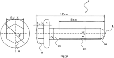
- Fig. 3a shows a further preferred embodiment of a temporary dental implant 1 with thread-shaped projections 20 with a thread core of 1.6 mm, a total length of 12 mm and a thread length of 8.0 mm.
- Fig. 4a another preferred embodiment of a temporary dental implant 1 with thread-shaped projections 20 with a Thread core of 2 mm, a total length of 14 mm and a thread length of 11.2 mm.
- Fig. 4b a further preferred embodiment of a temporary dental implant 1 with thread-shaped projections 20 with a thread core of 2 mm, a total length of 14 mm and a thread length of 7.2 mm.
- Fig.5 a further preferred embodiment of a temporary dental implant 1 with thread-shaped projections 20 with a thread core of 2.4 mm, a total length of 16 mm and a thread length of 12 mm.
- Fig.6 a further preferred embodiment of a temporary dental implant 1 with thread-shaped projections 20 with a thread core of 2.4 mm and a thread length of 14.5 mm and a total length of 18 mm.
- Fig.7 a further preferred embodiment of a temporary dental implant 1 with thread-shaped projections 20 with a thread core of 2.4 mm and a thread length of 14.5 mm and a total length of 20 mm.
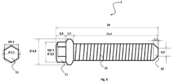
- Fig.8 shows a further preferred embodiment of a temporary dental implant 1 with thread-shaped projections, with a thread core of 2.4 mm and a thread length of 15.4 mm and a total length of 18 mm.
- the preferred embodiments of the temporary dental implant according to the invention preferably have total lengths of 10 mm, 14 mm, 16 mm, 18 mm and 20 mm and preferably thread lengths of 7.2 mm, 9.2 mm, 11.2 mm, 12 mm, 14.5 mm and 15.4 mm.
- the surfaces of the temporary dental implants are advantageously smooth, not roughened or treated. As a result, the growth of the temporary dental implant into the bone can be delayed. The edges of the screw body 11 are broken.
- Fig. 9a shows a screw adapter 40 comprising a screw receptacle 41 and a temporary dental implant 1 with a screw body 21.
- the screw receptacle 41 and the screw adapter 40 advantageously comprise a body made of a material combination of a zirconium oxide (ZrO 2 ) and an aluminum oxide (Al 2 O 3 ) or a material combination of a zirconium oxide (ZrO 2 ) and a dimer trioxide (Er 2 O 3 ).
- the screw receptacle 41 and the screw adapter 40 can also comprise a zirconium ceramic such as a TZP ceramic, an ATZ ceramic and/or a ZTA ceramic and/or a TZ-PX-525 ceramic.
- the screw body 21 made of a material combination of a zirconium oxide (ZrO 2 ) and an aluminum oxide (Al 2 O 3 ) or a material combination of a zirconium oxide (ZrO 2 ) and a diatomaceous earth trioxide (Er 2 O 3 ) is firmly connected to a screw adapter 40 and transmits a torque M from a drive (not shown) to the screw head 11.
- Fig. 9b shows a screw adapter 40 comprising a screw receptacle 41 and a temporary dental implant 1 with a screw body 21.
- the screw adapter 40 in this embodiment comprises a continuous body made of a material combination of a zirconium oxide (ZrO 2 ) and an aluminum oxide (Al 2 O 3 ) or a material combination of a zirconium oxide (ZrO 2 ) and a diatomite trioxide (Er 2 O 3 ), which transmits the torque M from the drive (not shown) to the screw head 11.
- the surface of the screw adapter 41 comprises a material combination of a zirconium oxide (ZrO 2 ) and an aluminum oxide (Al 2 O 3 ) or a material combination of a zirconium oxide (ZrO 2 ) and a diatomite trioxide (Er 2 O 3 ) and provides the screw receptacle 41.
- Fig.10 shows different views of a preferred embodiment of a screw adapter 40.
- the materials used consisting of a material combination of zirconium oxide (ZrO 2 ) and aluminum oxide (Al 2 O 3 ) or a material combination of zirconium oxide (ZrO 2 ) and dimer trioxide (Er 2 O 3 ), as well as their material combinations, have the advantageous material properties of being neutral, biocompatible, non-metallic, non-magnetic, non-conductive and non-radioactive. These materials and material combinations do not react with body fluids. Even if these materials and material combinations are exposed to strong acids, these materials are not attacked. They are stable, corrosion-resistant and durable.
- the temporary dental implant can be screwed in and/or removed germ-free and sterile and abrasion on the screw head of the temporary dental implant is avoided.
- Fig. 11 shows a temperature-pressure curve of a preferred embodiment of a HIP cycle.
- a pressure vessel filled with samples is evacuated for a period of 5 minutes at about 1.2 mbar. After 3 purging cycles with a protective gas such as argon, the pressure vessel is evacuated again for a period of about 5 minutes at about 1.2 mbar.
- the pressure is then built up to 200 bar.
- the temperature is then increased to approx. 1350°C at a rate of 10 K/min. During the heating process, the pressure is further increased to approx. 1500 bar.
- Figure 12 is a schematic view of drilling and inserting a temporary dental implant into a patient's base bone.
- a maximum permissible torque is applied depending on the diameter of the temporary dental implant 1.
- the screwdriver 45 includes another screw adapter that can be brought into engagement with the screw adapter 40.
- the final fixation is carried out using a torque ratchet 47. This ensures that the maximum permissible torque is not exceeded and that impairment or damage to the temporary dental implant 1 is prevented.
Landscapes
- Chemical & Material Sciences (AREA)
- Engineering & Computer Science (AREA)
- Ceramic Engineering (AREA)
- Health & Medical Sciences (AREA)
- Manufacturing & Machinery (AREA)
- Materials Engineering (AREA)
- Structural Engineering (AREA)
- Organic Chemistry (AREA)
- Composite Materials (AREA)
- Oral & Maxillofacial Surgery (AREA)
- Orthopedic Medicine & Surgery (AREA)
- Dentistry (AREA)
- Epidemiology (AREA)
- Life Sciences & Earth Sciences (AREA)
- Animal Behavior & Ethology (AREA)
- General Health & Medical Sciences (AREA)
- Public Health (AREA)
- Veterinary Medicine (AREA)
- Inorganic Chemistry (AREA)
- Materials For Medical Uses (AREA)
- Dental Preparations (AREA)
- Dental Prosthetics (AREA)
Abstract
Description
- Die vorliegende Erfindung betrifft ein Zahnimplantat, vorzugsweise ein temporäres Zahnimplantat, welches universell einsetzbar ist. Das Zahnimplantat umfasst eine Zirkoniumdioxid-Keramik, insbesondere eine Materialkombination aus einem Zirkonoxid (ZrO2) und einem Aluminiumoxid (Al2O3) oder eine Materialkombination aus einem Zirkonoxid (ZrO2) und einem Dierbiumtrioxid (Er2O3) für den medizinischen Einsatz. Ferner betrifft die vorliegende Erfindung ein Verfahren zur Herstellung eines temporären Zahnimplantats.
- Zahnimplantate/Implantate werden in der zahnärztlichen Therapie verwendet, um einen oder mehrere erkrankte oder fehlende Zähne vollständig zu ersetzen.
- Temporäre Implantate werden in der Medizin eingesetzt, um eine stabile Fixation zu ermöglichen.
- Häufig werden temporäre Zahnimplantate aus Titan gewählt. Ein Belassen der temporären Implantate als Implantat im Patienten ist möglich.
- Zur Anwendung in der präimplantologischen augmentativen Chirurgie sind Mikroschrauben zur Fixation sehr kleiner Knochenfragmente bekannt.
- Dabei weisen Mikroschrauben aus Chrom-Kobalt-Molybdän-Legierungen als Implantat in der Regel neben einer guten Gewebeintegration und Entfernbarkeit zudem eine gute Rigidität in der Fixation der Fragmente auf.
- Temporäre Zahnimplantate sind in der maxillofacialen Traumatologie im Einsatz. Hierbei war ihre Hauptaufgabe, eine Kontakt- oder Distanzosteogenese mit hinreichender Rigidität im Bereich der Knochen des Gesichtsschädels herzustellen. Da die Stabilisierung der Fragmente im Vordergrund stand, wurde auf eine ausreichende Dimensionierung des Materials geachtet, was aber die Reposition von Frakturen des Gesichtsschädels mit geringer Fragmentgröße erschwerte. Aus diesem Grund wurden temporäre Zahnimplantate entwickelt, die auch die Fixierung kleinerer Fragmente möglich machten.
- Die präimplantologische augmentative Chirurgie stellte höhere Anforderungen an die Feinheit der Materialien. Dies führte zu der Entwicklung von temporären Zahnimplantaten, die die Fixation sehr kleiner Knochenfragmente ermöglichen. Sehr kleine Osteosyntheseschrauben aus Titan zeigen aber aufgrund einer partiellen Osseointegration oft das Problem einer erschwerten Entfernbarkeit. Schrauben aus Chrom-Kobalt-Molybdän-Legierungen weisen neben guter Gewebeintegration und Entfernbarkeit zudem eine gute Rigidität in der Fixation der Fragmente auf. Im Handel werden Mikroschrauben mit einem Durchmesser von 1,0 mm bis 1,2 mm vertrieben, die aus rostfreiem, medizinischem Stahl hergestellt wurden, die die Vorteile eines geringen Durchmessers mit guter Gewebeintegration und Entfernbarkeit verbinden.
- Praktische Einsatzfälle von temporären Zahnimplantaten bzw. Knochenimplantaten, auch allgemein als Implantate bezeichnet, lassen teilweise eine Unverträglichkeit bei der Gewebeintegration der Materialien von Stahl, Stahllegierungen, Titan, Titanlegierungen oder Chrom-Kobalt-Molybdän-Legierungen mit dem Ziel-Organismus erkennen, in welchem ein temporäres Zahnimplantat eingesetzt werden soll.
- Ein Zahnimplantat, insbesondere ein temporäres Zahnimplantat oder ein Knochenimplantat aus Metall, Metalllegierungen oder Hybridmaterialien ist potential reaktiv bei Kontakt mit biologischem Gewebe und mit Körperflüssigkeiten und es können Unverträglichkeiten, Allergien und abstoßende Reaktionen hervorrufen werden.
- Es ist deshalb Aufgabe der vorliegenden Erfindung ein temporäres Zahnimplantat und ein Verfahren zur Herstellung eines temporären Zahnimplantats für Organismen mit Unverträglichkeit bei der Gewebeintegration gegenüber Metallen, Metalllegierungen, Hybridmaterialien, wie beispielsweise Titan, Titanlegierungen oder Chrom-Kobalt-Molybdän-Legierungen bereitzustellen, welche eine hohe mechanische Festigkeit aufweisen, die bei der Gewebeintegration verträglich sind die in eine für die Gewebeintegration im Ziel-Organismus verträgliche integrierbare alternative Materialzusammensetzung umfassen. Ferner sollen die Nachteile des Standesder-Technik überwunden werden können.
- Die Aufgabe wird durch ein erfindungsgemäßes temporäres Zahnimplantat gemäß den Merkmalen des unabhängigen Patentanspruchs 1 gelöst.
- Ferner wird die Aufgabe durch ein erfindungsgemäßes Verfahren zur Herstellung eines temporären Zahnimplantats bzw. eines Knochenimplantats gemäß den Merkmalen des unabhängigen Patentanspruchs 17 gelöst.
- Weitere vorteilhafte Ausgestaltungen der Lösung finden sich in den abhängigen Patentansprüchen.
- Ein erfindungsgemäßes temporäres Zahnimplantat umfasst eine Materialkombination aus Zirkoniumdioxid-Keramik.
- Vorteilhafterweise umfasst das temporäre Zahnimplantat eine Materialkombination aus einem Zirkonoxid (ZrO2) und einem Aluminiumoxid (Al2O3) oder eine Materialkombination aus einem Zirkonoxid (ZrO2) und einem Dierbiumtrioxid (Er2O3).
- Die Verwendung von temporären Zahnimplantaten, die diese Materialkombinationen umfasst, stellt eine neue Entwicklung in der Befestigung und Reposition in rekonstruktiver Augmentation von Knochendefekten dar. Eine Materialkombination aus Zirkoniumdioxid-Keramik, vorzugsweise eine Materialkombination aus einem Zirkonoxid (ZrO2) und einem Aluminiumoxid (Al2O3) oder eine Materialkombination aus einem Zirkonoxid (ZrO2) und einem Dierbiumtrioxid (Er2O3), bietet den Vorteil, dass dieses temporäre Zahnimplantat bei einem Patienten keine Unverträglichkeiten hervorruft. Diese Materialkombinationen sind biologisch 100% neutral, weisen eine hohe Stabilität und Festigkeit auf und sind sehr verträglich.
- Die verwendeten Materialien Zirkonoxid (ZrO2), Aluminiumoxid (Al2O3) und Dierbiumtrioxid (Er2O3) sowie deren Materialkombinationen weisen die vorteilhaften Materialeigenschaften auf, dass sie neutral, biokompatibel, d. h. gut gewebeverträglich im Kontakt mit Knochen und Weichgewebe, mineralisch, nicht metallisch, nicht magnetisch, nicht stromleitend und nicht radioaktiv sind. Diese Materialien und Materialkombinationen reagieren nicht mit Körperflüssigkeiten. Selbst wenn diese Materialien und Materialkombinationen starken Säuren ausgesetzt werden, werden diese Materialien nicht angegriffen. Sie sind stabil, korrosionsbeständig und langlebig.
- Das erfindungsgemäße temporäre Zahnimplantat kann insbesondere in folgenden Anwendungsbereichen eingesetzt werden.
- > Osteosynthese
- > Zum Positionieren/Befestigen von Hilfsmitteln für die gesteuerte Knochenregeneration
- > Abstützung für provisorische Prothesen, okklusale Abstützung
- > Augmentat Fixierung / Halter
- > Titankäfige Fixierungen
- In einer bevorzugten Ausführungsform ist das Zirkonoxid (ZrO2) mit Yttriumoxid (Y2O3) als Stabilisator dotiert. Vorteilhafterweise liegt die Konzentration von Yttriumoxid (Y2O3) zwischen 2 Gew% und 8 Gew%, insbesondere zwischen 3 Gew% und 6 Gew.%.
- Das Zahnimplantat kann als temporäres Zahnimplantat ausgebildet sein. In diesem Fall verbleibt das Zahnimplantat maximal ein Jahr im Kiefer des Patienten. Beispielsweise kann sich ein Implantat zwischen drei und sechs Monaten im Kiefer eines Patienten befinden. Bei einer Prothesen-Fixation kann das Zahnimplantat länger als sechs Monate im Kiefer des Patienten verbleiben.
- In einem bevorzugten Ausführungsbeispiel umfasst das Zahnimplantat eine Mikro-Osteosyntheseschraube.
- Ein temporäres Zahnimplantat kann auch ein Knochenimplantat, eine Knochen-blök-Granulat-Augmentat-Schraube oder dergleichen sein. Das Befestigen, Einbringen, Rekonstruieren erfolgt mittels der Augmentation. In der Zahnmedizin versteht man unter Augmentation den Wiederaufbau von abgebautem Kieferknochen durch Eigenknochen oder Fremdmaterial, insbesondere um ausreichend Knochenangebot zu schaffen, damit eine Zahnprothese auf dem Kieferkamm stabilisiert werden kann oder ein Zahnimplantat eingesetzt werden kann. Verfahren der Augmentation werden auch in der Parodontologie angewandt, um durch Parodontitis abgebauten Alveolarknochen wieder aufzubauen.
- Ein Belassen des temporären Zahnimplantates bzw. der temporären Zahnimplantate als Implantat bzw. Implantate im Patienten ist möglich.
- Zum Einsetzen des temporären Zahnimplantats, muss im Knochen vorgebohrt werden. Ein Bohrer umfasst vorteilhafterweise mindestens den Kerndurchmesser des Zahnimplantats, insbesondere + 0,2 mm des Kerndurchmessers des temporären Zahnimplantats, abhängig von der Knochenqualität-/dichte. Beispielsweise weist der Bohrer einen Durchmesser von 2,85 mm auf. Der Bohrer umfasst vorzugsweise einen Keramikbohrer. Ein Keramik-Senkbohrer, vorzugsweise mit einem Durchmesser von 4,4 mm, kann zum Ausbilden eines Senkloches bzw. einer kegelförmigen Erweiterung verwendet werden. Der Keramikbohrer und der Keramik-Senkbohrer kann eine Materialkombination aus Zirkoniumdioxid-Keramik, vorzugsweise eine Materialkombination aus einem Zirkonoxid (ZrO2) und einem Aluminiumoxid (Al2O3) oder eine Materialkombination aus einem Zirkonoxid (ZrO2) und einem Dierbiumtrioxid (Er2O3) umfassen.
- Das temporäre Zahnimplantat kann als Hilfsmittel zum Befestigen von Augmentaten bei Knochendefekten wie Osteosynthese, Rekonstruktionen, Implantologie und bei der Mund- und-, Kiefer,- und Gesichtschirurgie dienen. Ferner kann das temporären Zahnimplantat auch beim Anbringen und Halten von Prothesen verwendet werden.
- Bevorzugterweise ist das Zirkonoxid (ZrO2) Yttrium stabilisiert.
- Vorteilhafterweise umfasst die Konzentration des Zirkonoxids mehr als 80 Gew%, insbesondere mehr als 90 Gew%, bevorzugterweise mehr als 94,5 Gew%.
- Bevorzugterweise umfasst die Konzentration des Aluminiumoxids weniger als 10 Gew%, insbesondere weniger als 7 Gew%, bevorzugterweise weniger als 5,5 Gew%.
- Vorteilhafterweise umfasst das Dierbiumtrioxid (Er2O3) eine Konzentration von weniger als 10 Gew%, insbesondere von weniger als 7 Gew%, bevorzugterweise von weniger als 5 Gew%. Diese Materialkombination von Zirkonoxid (ZrO2) und Dierbiumtrioxid (Er2O3) stellt eine hochfeste Keramik zur Verfügung.
- Die Herstellung einer Materialkombination aus einem Zirkonoxid (ZrO2) und einem Aluminiumoxid (Al2O3) oder einer Materialkombination aus einem Zirkonoxid (ZrO2) und einem Dierbiumtrioxid (Er2O3) erfolgt bevorzugterweise in einem HIP-Prozess. Unter HIP versteht man heißisostatisches Pressen. Dies ist eine Entwicklung in der Fertigungstechnik, bei der Pulver und Feststoffe, besonders Keramiken und Metalle, gleichzeitig heiß gepresst und gesintert werden.
- Die temporären Zahnimplantate werden einem HIP-Prozess unterzogen, um die Qualität zu steigern, Hierdurch können insbesondere das Gefüge verdichtet werden und Nano-Risse können verkleinert bzw. geschrumpft werden.
- Ein temporäres Zahnimplantat kann einen Schraubkörper und einen Schraubenkopf umfassen.
- Bei der temporären Zahnimplantatsausführung ist das Folgende zu berücksichtigen.
- Der Schraubenkörper kann vorteilhafterweise einen Durchmesser im Gewindekern von 1,0 mm bis 4,5 mm, insbesondere einen Durchmesser im Gewindekern von 1,5 mm bis 4,0 mm, bevorzugterweise einen Durchmesser im Gewindekern von 2,0 mm bis 3,5 mm, aufweisen.
- Der Schraubkörper weist vorteilhafterweise eine Gewindelänge von 8 mm bis 18 mm auf. Die Gesamtlänge des Schraubkörpers kann zwischen 10 mm bis 25 mm, vorzugsweise zwischen 14 mm und 20 mm, liegen.
- In einem bevorzugten Ausführungsbeispiel umfasst das temporäre Zahnimplantat an dem Schraubenkörper ein durchgängiges Gewinde bis an den Schraubenkopf. Vorteilhafterweise kann hierdurch das Ein- und Herausschrauben des temporären Zahnimplantates sichergestellt werden.
- Die Oberflächen bleiben nach der mechanischen Bearbeitung unbehandelt. Dadurch kann ein Anwachsen des Zahnimplantats am Knochen verzögert werden. Die Kanten des Schraubkörpers sind vorteilhafterweise gebrochen.
- Es ist von Vorteil, dass das temporäre Zahnimplantat ein Drehmoment bis zu 100 Ncm standhält, ohne Schaden zu nehmen. Beim Eindrehen des temporären Zahnimplantats in den Kiefer eines Patienten treten Drehmomentkräfte von 30 bis 35 Ncm auf, wodurch eine hohe Sicherheit bereitgestellt werden kann. Der Sicherheitsfaktor beträgt größer 3. Ferner kann hierdurch verhindert werden, dass die temporären Zahnimplantate beim Eindrehen nicht brechen. Der Schraubenadapter weist einen Sicherheitsfaktor von größer 4 auf.
- Vorzugsweise umfasst ein temporäres Zahnimplantat, die folgenden Maßkombinationen:
- a)
- Gesamtlänge 10mm
- Gewindelänge 7,2mm
- Gewindekern 1,6 mm
- Schlüsselweite SW 3 mm
- b)
- Gesamtlänge 12 mm
- Gewindelänge 9,2 mm
- Gewindekern 1,6 mm
- Schlüsselweite SW 3 mm
- c)
- Gesamtlänge 14 mm
- Gewindelänge 11,2 und 7,2 mm
- Gewindekern 2 mm
- Schlüsselweite SW 3 mm
- d)
- Gesamtlänge 16 mm
- Gewindelänge 12 mm
- Gewindekern 2,4 mm
- Schlüsselweite SW 3 mm
- e)
- Gesamtlänge 18 mm
- Gewindelänge 14,5 mm
- Gewindekern 2,4 mm
- Schlüsselweite SW 3 mm
- f)
- Gesamtlänge 20 mm
- Gewindelänge 14,5 mm
- Gewindekern 2,4 mm
- Schlüsselweite SW 3 mm
- g)
- Gesamtlänge 18 mm
- Gewindelänge 15,4 mm
- Gewindekern 2,4mm
- Schlüsselweite SW 3 mm
- h)
- Gesamtlänge 10 mm
- Gewindelänge 6,0 mm
- Gewindekern 1,6 mm
- Schlüsselweite 3mm
- i)
- Gesamtlänge 12 mm
- Gewindelänge 8,0 mm
- Gewindekern 1,6 mm
- Schlüsselweite 3 mm
- Temporäre Zahnimplantate weisen im Unterschied zu größeren medizinischen Schrauben aufgrund ihres Einsatzgebietes im Bereich der Fixation sehr kleine und multiple, räumlich verteilte Knochenfragmente im Kieferknochenbereich als andere Festigkeitsanforderungen auf. Die Festigkeit und Fixation sind stabiler als bei Metallschrauben.
- Das erfindungsgemäße Verfahren zur Herstellung eines Zahnimplantats, vorzugsweise einer Mikro-Osteosyntheseschraube, in einem HIP-Zyklus umfasst die folgenden Schritte:
- Bereitstellen eines Druckbehälters,
- Bestücken des Druckbehälters mit einem noch rohen Zahnimplantats, vorzugsweise mit einer noch rohen Mikro-Osteosyntheseschraube,
- Evakuieren des Druckbehälters für eine Zeitdauer von ca. 5 Minuten bei einem Druck von ca. 1,2 mbar,
- Spülen des Druckbehälters mit einem Schutzgas,
- erneutes Evakuieren des Druckbehälters für eine Zeitdauer von ca. 5 Minuten bei einem Druck von ca. 1,2 mbar,
- Druckaufbau auf bis ca. 200 bar,
- Aufheizen mit einer Rate von 10 K/min auf eine Temperatur von ca. 1350°C,
- Während des Aufheizens, Erhöhung des Druckes im Druckbehälter auf ca. 1.500 bar,
- Halten dieses Zustandes für eine Zeitdauer von ca. 2 Stunden bei einer Temperatur von 1.350 °C und einem Druck von ca. 1.500 bar, und anschließend
- natürliche Abkühlung auf eine Temperatur von ca. 300 °C,
- Dekomprimieren auf Atmosphärendruck,
- Entnahme des Zahnimplantats bzw. der Mikro-Osteosyntheseschraube.
- Der Fachmann erkennt, dass gleichzeitig mehrere temporäre Zahnimplantate mittels des Herstellungsverfahrens herstellbar sind.
- In einer bevorzugten Ausführungsform wird in einem HIP-Zyklus das Material Zirkonoxid (ZrO2), insbesondere Yttrium-Zirkonoxid, mit 94,80% Gew% und Aluminiumoxid (Al2O3) mit < 5 Gew% heißisostatisch nachverdichtet.
- Der HIP-Zyklus wird bevorzugterweise nach einem definierten Temperatur-Druck-Programm in einer Schutzgas-Atmosphäre durchgeführt:
In Vorbereitung auf den HIP-Prozess wird ein mit Proben bestückter Druckbehälter für eine Dauer von 5 min bei etwa 1,2 mbar evakuiert. Nach 3 Spüldurchläufen mit einem Schutzgas wie beispielsweise Argon wird der Druckbehälter erneut für eine Dauer von 5 min bei etwa 1,2 mbar evakuiert. - Anschließend erfolgt ein Druckaufbau bis 200 bar. Dann wird mit einer Rate von 10 K/min auf ca. 1350°C aufgeheizt. Während des Aufheizprozesses erfolgt ein weiterer Druckaufbau bis ca. 1500 bar.
- Nach einer Haltezeit von ca. zwei Stunden bei 1350 °C und 1500 bar erfolgt eine natürliche Kühlung auf ca. 300 °C. Im Anschluss danach wird auf Atmosphärendruck dekomprimiert.
- Ein temporäres Zahnimplantat, welches nach dem vorgenannten HIP-Verfahren hergestellt ist, weist überraschenderweise hohe mechanische Festigkeiten auf. Ferner ist von Vorteil, dass das erfindungsgemäße temporäre Zahnimplantat, das eine Materialkombination aus Zirkonoxid und Aluminiumoxid umfasst, eine hohe Verträglichkeit im Vergleich mit den bisher verwendeten Metallen, Metalllegierungen oder Hybridmaterialien wie Titan- oder Chrom-Kobalt-Molybdän-Legierungen und eine sehr gute Integrierbarkeit in den Ziel-Organismus aufweist.
- In einer besonders vorteilhaften Ausgestaltung wird ein temporäres Zahnimplantat bereitgestellt, die eine Materialkombination aus Zirkonoxid (ZrO2), insbesondere Yttrium-Zirkonoxid, mit 94,80% Gew% und Aluminiumoxid (Al2O3) mit < 5 Gew% umfasst, die heiß-isostatisch nachverdichtet ist. Das temporäre Zahnimplantat kann an seiner Oberfläche Vorsprünge aufweisen, welche die Oberfläche eines Zahnimplantat-Verbindungselements, bezüglich des Knochengewebes, in welches das Zahnimplantat-Verbindungselement einbringbar ist, vergrößern kann und dadurch die Festigkeit der Verbindung zwischen dem Zahnimplantat-Verbindungselement und dem Knochengewebe unterstützen kann und dabei mit dem Knochengewebe des Ziel-Organismus verträglich und ohne Absplitterungen des temporären Zahnimplantats integrierbar ausbildbar ist.
- Das temporäre Zahnimplantat weist vorteilhafterweise eine definierte Querschnittsebene q mit einem definierten Querschnitt Q und eine definierte Länge L auf. Der Querschnitt Q durch das temporäre Zahnimplantat, weist im größten Durchmesser zur Länge L des temporären Zahnimplantats ein Verhältnis von > 2 auf. Das heißt, das temporäre Zahnimplantat ist länger als ihr Querschnitt Q. Eine Achse, die im Wesentlichen parallel, d.h. in einem Winkel von <= +- 70 Grad, vorzugsweise im Winkel von 90 Grad +- 5 Grad zur Querschnittsebene q entlang der Länge L des temporären Zahnimplantats verläuft, wird in der Folge als Längsachse des temporären Zahnimplantats bezeichnet. Der Querschnitt Q entlang der Längsachse L des temporären Zahnimplantats kann variieren.
- Entlang der Längsachse auf der Oberfläche eines Querschnitts Q des temporären Zahnimplantats angeordnete Vorsprünge können gewindeartig um einen Kern mit einem runden Querschnitt Q des temporären Zahnimplantats, angeordnet sein und eine Höhe von 10% bis 30% des an der jeweiligen Position entlang der Längsachse des Implantat-Verbindungselements herrschenden Gesamtdurchmessers des Querschnitts des temporären Zahnimplantats aufweisen. Der Kern kann entlang seiner Längsachse zylindrisch oder auch wenigstens teilweise kegelförmig ausgeführt sein, um je nach Einsatzort im Knochengewebe die Integrierbarkeit des temporären Zahnimplantats zu unterstützen.
- Der Fachmann erkennt, dass das temporäre Zahnimplantat auch stiftartig zum Vorschub, beispielsweise zum Einpressen in das Knochengewebe ausgeführt sein kann und dabei beliebige Querschnittsform aufweisen kann, wobei die Vorsprünge passend zur Vorschubrichtung entlang der Längsachse des temporären Zahnimplantats angeordnet sind.
- Der Fachmann erkennt ferner, dass die zuvor beschriebene bevorzugte Ausführungsform auch einen HIP-Zyklus mit der Materialkombination einem Zirkonoxid (ZrO2) und einem Dierbiumtrioxid (Er2O3) entsprechend durchlaufen kann.
- Die vorliegende Erfindung bezieht sich auch auf einen Schraubenadapter zum Ein- und/oder Herausdrehen eines erfindungsgemäßen temporären Zahnimplantats, umfassend eine Schraubenaufnahme und einen Schraubenkörper, wobei die Schraubenaufnahme eine Zirkoniumdioxid-Keramik umfasst, bevorzugterweise eine Materialkombination aus einem Zirkonoxid (ZrO2) und einem Aluminiumoxid (Al2O3) oder eine Materialkombination aus einem Zirkonoxid (ZrO2) und einem Dierbiumtrioxid (Er2O3) umfasst. Beim Ein- und/oder Herausdrehen des temporären Zahnimplantats mittels der Schraubenaufnahme des Schraubenadapters aus einer Zirkoniumdioxid-Keramik, bevorzugterweise aus einer Materialkombination aus einem Zirkonoxid (ZrO2) und einem Aluminiumoxid (Al2O3) oder einer Materialkombination aus einem Zirkonoxid (ZrO2) und einem Dierbiumtrioxid (Er2O3), wird ein keimfreies und steriles Arbeiten ermöglicht und ein Abrieb am Schraubenkopf des temporären Zahnimplantats vermieden. Bei der Verwendung eines Schraubenadapters aus Metallen oder Metalllegierungen wie beispielsweise Stahl, Stahllegierungen, Titan, Titanlegierungen oder Chrom-Kobalt-Molybdän-Legierungen, hat das Ein- und/oder Herausdrehen eines temporären Zahnimplantats einen Abrieb zur Folge. Ein Abrieb eines Metalls oder einer Metalllegieren sollte vermieden werden, da zum einen der Abrieb im Mund eines Patienten verbleiben kann und der Patient den Abrieb verschlucken könnte. Ferner hat ein Abrieb zur Folge, dass beim Herausdrehen des temporären Zahnimplantats die Schraubenaufnahme nicht mehr richtig greift und das Herausdrehen nicht mehr oder nur schwer möglich ist.
- Der Schraubenkörper des Schraubenadapters umfasst eine Zirkoniumdioxid-Keramik, insbesondere eine Materialkombination aus einem Zirkonoxid (ZrO2) und einem Aluminiumoxid (Al2O3) oder eine Materialkombination aus einem Zirkonoxid (ZrO2) und einem Dierbiumtrioxid (Er2O3). Dies bietet den Vorteil, dass eine Reaktion mit Körperflüssigkeiten vermieden wird, ein Angreifen verhindert wird, selbst wenn diese Materialien und Materialkombinationen starken Säuren ausgesetzt werden. Ein Schraubenkörper des Schraubenadapters aus einer Zirkoniumdioxid-Keramik, insbesondere aus einer Materialkombination aus einem Zirkonoxid (ZrO2) und einem Aluminiumoxid (Al2O3) oder einer Materialkombination aus einem Zirkonoxid (ZrO2) und einem Dierbiumtrioxid (Er2O3) stellt ein stabiles, korrosionsbeständiges und langlebiges Bauteil zur Verfügung.
- Vorteilhafterweise kann die Zirkoniumdioxid-Keramik eine TZP-Keramik, eine ATZ-Keramik, eine ZTA-Keramik und/oder TZ-PX-525-Keramik umfassen.
- Im Folgenden werden anhand von Figuren Ausführungsbeispiele der vorliegen Erfindung beschrieben. Diese Figuren zeigen in
- Fig. 1
- eine Prinzipdarstellung eines erfindungsgemäßen temporären Zahnimplantats,
- Fig 2
- eine bevorzugte Ausführungsform eines temporären Zahnimplantats mit gewindeförmigen Vorsprüngen, mit einem Gewindekern von 1,6 mm und einer Gewindelänge von 7,2 mm,
- Fig. 2a
- eine bevorzugte Ausführungsform eines temporären Zahnimplantats mit gewindeförmigen Vorsprüngen, mit einem Gewindekern von 1,6 mm und einer Gewindelänge von 6,0 mm,
- Fig 3
- eine bevorzugte Ausführungsform eines temporären Zahnimplantats mit gewindeförmigen Vorsprüngen, mit einem Gewindekern von 1,6 mm und einer Gewindelänge von 9,2 mm,
- Fig. 3a
- eine bevorzugte Ausführungsform eines temporären Zahnimplantats mit gewindeförmigen Vorsprüngen, mit einem Gewindekern von 1,6 mm und einer Gewindelänge von 8,0 mm,
- Fig 4a
- eine weitere bevorzugte Ausführungsform eines temporären Zahnimplantats mit gewindeförmigen Vorsprüngen, mit einem Gewindekern von 2 mm und einer Gewindelänge von 11,2 mm,
- Fig. 4b
- eine weitere bevorzugte Ausführungsform eines temporären Zahnimplantats mit gewindeförmigen Vorsprüngen, mit einem Gewindekern von 2 mm und einer Gewindelänge von 7,2 mm,
- Fig 5
- eine weitere bevorzugte Ausführungsform eines temporären Zahnimplantats mit gewindeförmigen Vorsprüngen, mit einem Gewindekern von 2,4 mm und einer Gewindelänge von 12 mm,
- Fig 6
- eine weitere bevorzugte Ausführungsform eines temporären Zahnimplantats mit gewindeförmigen Vorsprüngen, mit einem Gewindekern von 2,4 mm und einer Gewindelänge von 14,5 mm und einer Gesamtlänge von 18 mm,
- Fig 7
- eine weitere bevorzugte Ausführungsform eines temporären Zahnimplantats mit gewindeförmigen Vorsprüngen, mit einem Gewindekern von 2,4 mm und einer Gewindelänge von 14,5 mm und einer Gesamtlänge von 20 mm,
- Fig. 8
- eine weitere bevorzugte Ausführungsform eines temporären Zahnimplantats mit gewindeförmigen Vorsprüngen, mit einem Gewindekern von 2,4 mm und einer Gewindelänge von 15,4 mm und einer Gesamtlänge von 18 mm,
- Fig. 9a
- und
Fig. 9b . einen erfindungsgemäßen Schraubenadapter zum Ein- und/oder Herausdrehen eines temporären Zahnimplantats und - Fig. 10
- unterschiedliche Ansichten einer bevorzugten Ausführungsform eines Schraubenadapters,
- Fig. 11
- einen Temperatur-Druck-Verlauf einer bevorzugten Ausführungsform eines HIP-Zyklus, und
- Fig. 12
- eine schematische Ansicht einer Bohrung und eines Einsetzens eines temporären Zahnimplantats in einen Basisknochen eines Patienten.
- Ausführungsbeispiele der vorliegenden Erfindung werden nachfolgend beispielhaft beschrieben.
- Gleiche Bauteile wurden mit gleichen Bezugszeichen versehen.
-
Fig. 1 zeigt eine Prinzipdarstellung eines Implantat-Verbindungselements, welches vorzugsweise als temporäres Zahnimplantat ausgeführt ist. - Ein temporäres Zahnimplantat 1 umfasst eine Materialkombination aus einem Zirkonoxid (ZrO2), insbesondere Yttrium-Zirkonoxid, mit 94,80% Gew% und Aluminiumoxid (Al2O3) mit < 5 Gew%, wobei die Materialkombination heißisostatisch nachverdichtet ist. Das temporäre Zahnimplantat 1 weist an einer Oberfläche eines Kerns 10 Vorsprünge 20 auf, welche die Oberfläche des temporären Zahnimplantats 1 bezüglich eines Knochengewebes 30, in welches das temporäres Zahnimplantat 1 einbringbar ist, vergrößert. Dadurch wird die Festigkeit der Verbindung zwischen dem temporären Zahnimplantat 1 und dem Knochengewebe 30 unterstützt und erhöht. Dabei entsteht eine mit dem Knochengewebe 30 des Ziel-Organismus verträgliche Ausgestaltung, wobei das temporäre Zahnimplantat 1 ohne Absplitterungen integrierbar ist.
- Das temporäre Zahnimplantat 1 weist entlang der Längsachse jeweils eine definierte Querschnittsebene q mit einem potenziell variierenden definierten Querschnitt Q und einer definierten Länge auf. Der Querschnitt Q durch das temporäre Zahnimplantat 1 weist im größten Durchmesser zur Länge des temporären Zahnimplantats 1 ein Verhältnis von > 2 auf. Das heißt, das temporäre Zahnimplantat 1 ist länger als ihr Querschnitt Q. Der Querschnitt Q entlang der Längsachse L des temporären Zahnimplantats 1 kann variieren.
- Die Vorsprünge 20 des temporären Zahnimplantats 1 sind gewindeartig um den Kern 10 mit einem runden Querschnitt Q des temporären Zahnimplantats 1 angeordnet und weisen eine Höhe von bis zu 30%, insbesondere von bis zu 20% des an der jeweiligen Position entlang der Längsachse des temporären Zahnimplantats 1 herrschenden Gesamtdurchmessers des Querschnitts Q des temporären Zahnimplantats 1 auf. Das temporäre Zahnimplantat 1 ist in das Knochengewebe 30 integrierbar. Der Kern 10 kann entlang seiner Längsachse L zylindrisch oder auch wenigstens teilweise kegelförmig ausgeführt sein, um je nach Einsatzort im Knochengewebe 30 die Integrierbarkeit des temporären Zahnimplantats 1 zu unterstützen.
- Das temporäre Zahnimplantat 1 umfasst einen Kern 10 mit Vorsprüngen 20 und umfasst einen Schraubkörper 21 und einen Schraubenkopf 11 (siehe
Figuren 2 bis 7 ). Beim Schraubkopf 11 sind die Kanten gebrochen. Es soll dadurch verhindert werden, dass die Schleimhaut eines Patienten reißt, denn über die Schleimhaut wird das Augmentat mit Blut versorgt. Die Oberflächen des temporären Zahnimplantats 1 sind nicht bearbeitet, insbesondere nicht aufgeraut, so dass ein Anwachsen des temporären Zahnimplantats 1 am Knochen verzögert werden kann. - In einem weiteren Ausführungsbeispiel kann das temporäre Zahnimplantat 1 als Zahnimplantat-Verbindungselement stiftartig zum Vorschub, beispielsweise zum Einpressen in das Knochengewebe, ausgeführt sein und kann dabei eine beliebige Querschnittsform Q aufweisen, wobei die Vorsprünge 20 passend zur Vorschubrichtung entlang der Längsachse L des Zahnimplantat-Verbindungselements auf der Oberfläche des Kerns 10 angeordnet sind.
-
Fig 2 zeigt ein bevorzugtes Ausführungsbeispiel eines temporären Zahnimplantats 1 umfassend mit gewindeförmigen Vorsprüngen 20 mit einem Gewindekern von 1,6 mm, einer Gesamtlänge von 10 mm und einer Gewindelänge von 7,2 mm. -
Fig 2a zeigt ein bevorzugtes Ausführungsbeispiel eines temporären Zahnimplantats 1 umfassend mit gewindeförmigen Vorsprüngen 20 mit einem Gewindekern von 1,6 mm, einer Gesamtlänge von 10 mm und einer Gewindelänge von 6,0 mm. -
Fig 3 zeigt ein weiteres bevorzugtes Ausführungsbeispiel eines temporären Zahnimplantats 1 mit gewindeförmigen Vorsprüngen 20 mit einem Gewindekern von 1,6 mm, einer Gesamtlänge von 10 mm und einer Gewindelänge von 9,2 mm. -
Fig 3a zeigt ein weiteres bevorzugtes Ausführungsbeispiel eines temporären Zahnimplantats 1 mit gewindeförmigen Vorsprüngen 20 mit einem Gewindekern von 1,6 mm, einer Gesamtlänge von 12 mm und einer Gewindelänge von 8,0 mm. -
Fig. 4a ein weiteres bevorzugtes Ausführungsbeispiel eines temporären Zahnimplantats 1 mit gewindeförmigen Vorsprüngen 20 mit einem Gewindekern von 2 mm, einer Gesamtlänge von 14 mm und einer Gewindelänge von 11,2mm. -
Fig. 4b ein weiteres bevorzugtes Ausführungsbeispiel eines temporären Zahnimplantats 1 mit gewindeförmigen Vorsprüngen 20 mit einem Gewindekern von 2 mm, einer Gesamtlänge von 14 mm und einer Gewindelänge von 7,2mm. -
Fig. 5 ein weiteres bevorzugtes Ausführungsbeispiel eines temporären Zahnimplantats 1 mit gewindeförmigen Vorsprüngen 20 mit einem Gewindekern von 2,4 mm, einer Gesamtlänge von 16 mm und einer Gewindelänge von 12 mm. -
Fig. 6 ein weiteres bevorzugtes Ausführungsbeispiel eines temporären Zahnimplantats 1 mit gewindeförmigen Vorsprüngen 20 mit einem Gewindekern von 2,4 mm und einer Gewindelänge von 14,5 mm und einer Gesamtlänge von 18 mm. -
Fig. 7 ein weiteres bevorzugtes Ausführungsbeispiel eines temporären Zahnimplantats 1 mit gewindeförmigen Vorsprüngen 20 mit einem Gewindekern von 2,4 mm und einer Gewindelänge von 14,5 mm und einer Gesamtlänge von 20 mm. -
Fig. 8 zeigt eine weitere bevorzugte Ausführungsform eines temporären Zahnimplantats 1 mit gewindeförmigen Vorsprüngen, mit einem Gewindekern von 2,4 mm und einer Gewindelänge von 15,4 mm und einer Gesamtlänge von 18 mm. - Der Fachmann erkennt, dass die bevorzugten Ausführungsformen des erfindungsgemäßen temporären Zahnimplantats, bevorzugterweise Gesamtlängen von 10 mm, 14 mm, 16 mm, 18 mm und 20 mm und bevorzugterweise Gewindelängen von 7,2 mm, 9,2 mm, 11,2 mm, 12 mm, 14,5 mm und 15,4 mm aufweisen. Die Oberflächen der temporären Zahnimplantate sind vorteilhafterweise glatt, nicht aufgeraut bzw. nicht behandelt. Dadurch kann ein Anwachsen des temporären Zahnimplantats am Knochen verzögert werden. Die Kanten des Schraubkörpers 11 sind gebrochen.
-
Fig. 9a zeigt einen Schraubenadapter 40 umfassend eine Schraubenaufnahme 41 und ein temporäres Zahnimplantat 1 mit einem Schraubkörper 21. Die Schraubenaufnahme 41 und der Schraubenadapter 40 umfassen vorteilhafterweise einen Körper aus einer Materialkombination aus einem Zirkonoxid (ZrO2) und einem Aluminiumoxid (Al2O3) oder einer Materialkombination aus einem Zirkonoxid (ZrO2) und einem Dierbiumtrioxid (Er2O3). Die Schraubenaufnahme 41 und der Schraubenadapter 40 können auch eine Zirkonium-Keramik wie beispielsweise eine TZP-Keramik, eine ATZ-Keramik und/oder eine ZTA-Keramik und/oder eine TZ-PX-525-Keramik umfassen. Der Schraubkörper 21 aus einer Materialkombination aus einem Zirkonoxid (ZrO2) und einem Aluminiumoxid (Al2O3) oder einer Materialkombination aus einem Zirkonoxid (ZrO2) und einem Dierbiumtrioxid (Er2O3) ist mit einem Schraubenadapter 40 fest verbunden und überträgt ein Drehmoment M von einem Antrieb (nicht dargestellt) auf den Schraubenkopf 11. -
Fig. 9b zeigt einen Schraubenadapter 40 umfassend eine Schraubenaufnahme 41 und ein temporäres Zahnimplantat 1 mit einem Schraubkörper 21. Der Schraubenadapter 40 umfasst in diesem Ausführungsbeispiel einen durchgehenden Körper aus einer Materialkombination aus einem Zirkonoxid (ZrO2) und einem Aluminiumoxid (Al2O3) oder einer Materialkombination aus einem Zirkonoxid (ZrO2) und einem Dierbiumtrioxid (Er2O3), welcher das Drehmoment M von dem Antrieb (nicht dargestellt) auf den Schraubenkopf 11 überträgt. Die Oberfläche des Schraubenadapters 41 umfasst eine Materialkombination aus einem Zirkonoxid (ZrO2) und einem Aluminiumoxid (Al2O3) oder eine Materialkombination aus einem Zirkonoxid (ZrO2) und einem Dierbiumtrioxid (Er2O3) und stellt die Schraubenaufnahme 41 bereit. -
Fig. 10 zeigt unterschiedliche Ansichten einer bevorzugten Ausführungsform eines Schraubenadapters 40. - Die verwendeten Materialien aus einer Materialkombination aus einem Zirkonoxid (ZrO2) und einem Aluminiumoxid (Al2O3) oder einer Materialkombination aus einem Zirkonoxid (ZrO2) und einem Dierbiumtrioxid (Er2O3) sowie deren Materialkombinationen weisen die vorteilhaften Materialeigenschaften auf, dass sie neutral, biokompatibel, nicht metallisch, nicht magnetisch, nicht stromleitend und nicht radioaktiv sind. Diese Materialien und Materialkombinationen reagieren nicht mit Körperflüssigkeiten. Selbst wenn diese Materialien und Materialkombinationen starken Säuren ausgesetzt werden, werden diese Materialien nicht angegriffen. Sie sind stabil, korrosionsbeständig und langlebig. Es wird ein keimfreies und steriles Ein- und/oder Herausschrauben des temporären Zahnimplantats ermöglicht und es wird ein Abrieb am Schraubenkopf des temporären Zahnimplantats vermieden.
-
Fig. 11 zeigt einen Temperatur-Druck-Verlauf einer bevorzugten Ausführungsform eines HIP-Zyklus. - In Vorbereitung auf einen HIP-Prozess wird ein mit Proben bestückter Druckbehälter für eine Dauer von 5 min bei etwa 1,2 mbar evakuiert. Nach 3 Spüldurchläufen mit einem Schutzgas wie beispielsweise Argon wird der Druckbehälter erneut für eine Dauer von ca. 5 min bei etwa 1,2 mbar evakuiert.
- Anschließend erfolgt ein Druckaufbau bis 200 bar. Dann wird mit einer Rate von 10 K/min auf ca. 1350°C aufgeheizt. Während des Aufheizprozesses erfolgt ein weiterer Druckaufbau bis ca. 1500 bar.
- Nach einer Haltezeit von ca. zwei Stunden bei 1350 °C und 1500 bar erfolgt eine natürliche Kühlung auf ca. 300 °C. Im Anschluss danach wird auf Atmosphärendruck dekomprimiert.
- Das Verfahren zur Herstellung eines temporären Zahnimplantats 1, vorzugsweise einer Mikro-Osteosyntheseschraube, in einem HIP-Zyklus umfasst die folgenden Schritte:
- Bereitstellen eines Druckbehälters,
- Bestücken des Druckbehälters mit einem noch rohen Zahnimplantats 1, vorzugsweise mit einer noch rohen Mikro-Osteosyntheseschraube 1,
- Evakuieren des Druckbehälters für eine Zeitdauer von ca. 5 Minuten bei einem Druck von ca. 1,2 mbar,
- Spülen des Druckbehälters mit einem Schutzgas,
- erneutes Evakuieren des Druckbehälters für eine Zeitdauer von ca. 5 Minuten bei einem Druck von ca. 1,2 mbar,
- Druckaufbau auf bis ca. 200 bar,
- Aufheizen mit einer Rate von 10 K/min auf eine Temperatur von ca. 1350°C,
- Während des Aufheizens, Erhöhung des Druckes im Druckbehälter auf ca. 1.500 bar,
- Halten dieses Zustandes für eine Zeitdauer von ca. 2 Stunden bei einer Temperatur von 1.350 °C und einem Druck von ca. 1.500 bar, und anschließend
- natürliche Abkühlung auf eine Temperatur von ca. 300 °C,
- Dekomprimieren auf Atmosphärendruck,
- Entnahme des Zahnimplantats 1, bzw. der Mikro-Osteosyntheseschraube.
-
Figur 12 ist eine schematische Ansicht einer Bohrung und eines Einsetzens eines temporären Zahnimplantats in einen Basisknochen eines Patienten. - Ein Verfahren zum Einsetzen eines erfindungsgemäßen temporären Zahnimplantats 1 in einen Basisknochen 31 eines Patienten umfasst die folgenden Schritte:
- Setzen einer Bohrung durch ein Augmentat 32 und in einen Basisknochen 31 eines Patienten mittels eines Bohrers 35 aus einer Keramiklegierung vorzugsweise umfassend eine Zirkoniumdioxid-Keramik,
- Ausbilden eines Senkloches mittels eines Senkbohrers 36 aus einer Keramiklegierung, vorzugsweise umfassend eine Zirkoniumdioxid-Keramik, insbesondere umfassend eine Materialkombination aus einem Zirkonoxid (ZrO2) und einem Aluminiumoxid (Al2O3) oder eine Materialkombination aus einem Zirkonoxid (ZrO2) und einem Dierbiumtrioxid (Er2O3),
- Fixierung eines temporären Zahnimplantats 1 im Augmentat 32 mit Hilfe eines Schraubenadapters 40 umfassend eine Schraubenaufnahme 41 und einen Schraubenkörper, wobei die Schraubenaufnahme 41 eine Zirkoniumdioxid-Keramik umfasst, insbesondere eine Materialkombination aus einem Zirkonoxid (ZrO2) und einem Aluminiumoxid (Al2O3) oder eine Materialkombination aus einem Zirkonoxid (ZrO2) und einem Dierbiumtrioxid (Er2O3) umfasst.
- Bei der Fixierung des temporären Zahnimplantats 1 wird abhängig vom Durchmesser des temporären Zahnimplantats 1 ein maximal zulässiges Drehmoment angesetzt. Zunächst wird mittels eines Schraubendrehers 45 eine erste Fixierung des temporären Zahnimplantats vorgenommen. Der Schraubendreher 45 umfasst einen weiteren Schraubenadapter, der in Eingriff mit dem Schraubenadapter 40 bringbar ist. Die abschließende Fixierung erfolgt mittels einer Drehmomentratsche 47. Hierdurch wird sichergestellt, dass das maximal zulässige Drehmoment nicht überschritten wird und eine Beeinträchtigung oder Beschädigung des temporären Zahnimplantats 1 verhindert wird.
-
- 1
- Temporäres Zahnimplantat
- 10
- Kern
- 11
- Schraubenkopf
- 20
- Vorsprung
- 21
- Schraubkörper
- 30
- Knochengewebe
- 31
- Basisknochen
- 32
- Augmentat
- q
- Querschnittsebene
- Q
- Querschnitt
- L
- Längsachse
- 35
- Bohrer
- 36
- Senkbohrer
- 40
- Schraubenadapter
- 41
- Schraubenaufnahme
- 45
- Schraubendreher für Schraubenadapter
- 46
- weiterer Schraubenadapter
- 47
- Drehmomentratsche
- 50
- Soll-Temperatur in °C
- 60
- Ist-Temperatur "Obere Zone" in °C
- 70
- Ist-Temperatur "Untere Zone" in °C
- 80
- Behälterdruck in bar
Claims (15)
- Temporäres Zahnimplantat (1) umfassend eine Materialkombination aus einem Zirkonoxid (ZrO2) und einem Aluminiumoxid (Al2O3) oder eine Materialkombination aus einem Zirkonoxid (ZrO2) und einem Dierbiumtrioxid (Er2O3).
- Temporäres Zahnimplantat nach Anspruch 1, dadurch gekennzeichnet, dass das temporäres Zahnimplantat als Mikro-Osteosyntheseschraube ausgebildet ist.
- Temporäres Zahnimplantat (1) nach Anspruch 1, dadurch gekennzeichnet, dass das Zirkonoxid (ZrO2) Yttrium stabilisiert ist.
- Temporäres Zahnimplantat (1) nach Anspruch 1 oder 3, dadurch gekennzeichnet, dass das Zirkonoxids (ZrO2) eine Konzentration von mehr als 80 Gew%, insbesondere von mehr als 90 Gew%, bevorzugterweise von mehr als 94,5 Gew% aufweist.
- Temporäres Zahnimplantat (1) nach Anspruch 1, dadurch gekennzeichnet, dass das Aluminiumoxid (Al2O3) eine Konzentration von weniger als 10 Gew%, insbesondere von weniger als 7 Gew%, bevorzugterweise von weniger als 5,5 Gew% aufweist.
- Temporäres Zahnimplantat (1) nach Anspruch 1, dadurch gekennzeichnet, dass das Dierbiumtrioxid (Er2O3) eine Konzentration von weniger als 10 Gew%, insbesondere von weniger als 7 Gew%, bevorzugterweise von weniger als 5 Gew% aufweist.
- Temporäres Zahnimplantat (1) nach einem der vorherigen Ansprüche, dadurch gekennzeichnet, dass die Materialkombination aus einem Zirkonoxid (ZrO2) und einem Aluminiumoxid (Al2O3) oder die Materialkombination aus einem Zirkonoxid (ZrO2) und einem Dierbiumtrioxid (Er2O3) einem HIP-Prozesses unterziehbar ist.
- Temporäres Zahnimplantat (1) nach Anspruch 1, dadurch gekennzeichnet, dass zum Einsetzen des temporären Zahnimplantats (1) ein Vorbohren mittels eines Bohrers im Knochen eines Patienten erforderlich ist.
- Temporäres Zahnimplantat (1) nach einem der vorherigen Ansprüche, dadurch gekennzeichnet, dass das temporäre Zahnimplantat (1) einen Kern (10) und Vorsprünge (20), einen Schraubkörper (21) und einen Schraubenkopf (11) umfasst.
- Temporäres Zahnimplantat (1) nach Anspruch 9, dadurch gekennzeichnet, dass der Schraubenkörper (21) einen Durchmesser im Gewindekern zwischen 1,0 mm bis 4,5 mm, insbesondere einen Durchmesser zwischen 1,6 mm bis 4,0 mm, bevorzugterweise einen Durchmesser im Gewindekern zwischen 2,0 mm bis 3,0 mm, aufweist.
- Temporäres Zahnimplantat (1) nach Anspruch 9 oder 10, dadurch gekennzeichnet, dass der Schraubkörper (21) eine Gewindelänge zwischen 2 mm bis 15 mm aufweist.
- Temporäres Zahnimplantat (1) nach einem der Ansprüche 9 bis 11, dadurch gekennzeichnet, dass die Gesamtlänge des Schraubkörpers (21) zwischen 10 mm bis 25 mm, vorzugsweise zwischen 14 mm und 20 mm, liegt.
- Temporäres Zahnimplantat (1) nach einem der vorherigen Ansprüche, dadurch gekennzeichnet, dass an dem temporären Zahnimplantat (21) ein durchgängiges Gewinde bis an den Schraubenkopf (11) ausgebildet ist.
- Schraubenadapter (40) zum Ein- und/oder Herausdrehen eines temporären Zahnimplantats (1) gemäß einem der vorherigen Ansprüche 1 bis 13, umfassend eine Schraubenaufnahme (41) und einen Schraubenkörper (21), dadurch gekennzeichnet, dass die Schraubenaufnahme (41) eine Zirkoniumdioxid-Keramik umfasst, insbesondere eine Materialkombination aus einem Zirkonoxid (ZrO2) und einem Aluminiumoxid (Al2O3) oder eine Materialkombination aus einem Zirkonoxid (ZrO2) und einem Dierbiumtrioxid (Er2O3) umfasst.
- Verfahren zur Herstellung eines temporären Zahnimplantats (1), vorzugsweise einer Mikro-Osteosyntheseschraube, in einem HIP-Zyklus umfassend die folgenden Schritte:- Bereitstellen eines Druckbehälters,- Bestücken des Druckbehälters mit einem rohen temporären Implantat (1), vorzugsweise mit einer rohen Mikro-Osteosyntheseschraube,- Evakuieren des Druckbehälters für eine Zeitdauer von ca. 5 Minuten bei einem Druck von ca. 1,2 mbar,- Spülen des Druckbehälters mit einem Schutzgas,- erneutes Evakuieren des Druckbehälters für eine Zeitdauer von ca. 5 Minuten bei einem Druck von ca. 1,2 mbar,- Druckaufbau auf bis ca. 200 bar,- Aufheizen mit einer Rate von 10 K/min auf eine Temperatur von ca. 1350°C,- Während des Aufheizens, Erhöhung des Druckes im Druckbehälter auf ca. 1.500 bar,- Halten dieses Zustandes für eine Zeitdauer von ca. 2 Stunden bei einer Temperatur von 1.350 °C und einem Druck von ca. 1.500 bar, und anschließend- natürliche Abkühlung auf eine Temperatur von ca. 300 °C,- Dekomprimieren auf Atmosphärendruck.- Entnahme des Implantats (1), vorzugsweise der Mikro-Osteosyntheseschraube.
Applications Claiming Priority (1)
| Application Number | Priority Date | Filing Date | Title |
|---|---|---|---|
| DE102023000090.6A DE102023000090A1 (de) | 2023-01-12 | 2023-01-12 | Temporäres Zahnimplantat sowie ein Verfahren zur Herstellung eines temporären Zahnimplantats |
Publications (2)
| Publication Number | Publication Date |
|---|---|
| EP4410233A2 true EP4410233A2 (de) | 2024-08-07 |
| EP4410233A3 EP4410233A3 (de) | 2024-11-13 |
Family
ID=89573621
Family Applications (1)
| Application Number | Title | Priority Date | Filing Date |
|---|---|---|---|
| EP24151085.8A Pending EP4410233A3 (de) | 2023-01-12 | 2024-01-10 | Temporäres zahnimplantat sowie ein verfahren zur herstellung eines temporären zahnimplantats |
Country Status (2)
| Country | Link |
|---|---|
| EP (1) | EP4410233A3 (de) |
| DE (1) | DE102023000090A1 (de) |
Family Cites Families (9)
| Publication number | Priority date | Publication date | Assignee | Title |
|---|---|---|---|---|
| DE3325490A1 (de) * | 1983-07-14 | 1985-01-24 | Elektroschmelzwerk Kempten GmbH, 8000 München | Feuerfeste, elektrisch leitfaehige mischwerkstoffe und verfahren zu ihrer herstellung durch isostatisches heisspressen |
| EP0218853B1 (de) * | 1985-09-06 | 1994-11-09 | Toray Industries, Inc. | Verfahren zur Herstellung eines gesinterten Zirkonoxidmaterials |
| DE102005001185B4 (de) * | 2005-01-10 | 2009-09-10 | Bongard, Peter, Dr. | Zahnimplantat |
| DE102005013200B4 (de) * | 2005-03-16 | 2014-05-28 | Peter A. Ehrl | Zweiteiliges Zahnimplantat aus Keramik |
| RU2698021C1 (ru) * | 2013-12-04 | 2019-08-21 | 3М Инновейтив Пропертиз Компани | Стоматологическая заготовка для фрезерования, способ ее изготовления и использования |
| WO2015168332A2 (en) * | 2014-04-30 | 2015-11-05 | Osseodyne Surgical Solutions, Llc | Osseointegrative surgical implant |
| EP3659989A1 (de) * | 2018-11-29 | 2020-06-03 | Ivoclar Vivadent AG | Schlicker und verfahren zur herstellung von keramischen und glaskeramischen 3d strukturen |
| EP3811896B1 (de) * | 2019-10-22 | 2024-05-01 | Nadja Rohr | Dentalimplantat |
| DE102020210075A1 (de) * | 2020-08-07 | 2022-02-10 | Nature Implants GmbH | Dentalimplantat |
-
2023
- 2023-01-12 DE DE102023000090.6A patent/DE102023000090A1/de active Pending
-
2024
- 2024-01-10 EP EP24151085.8A patent/EP4410233A3/de active Pending
Also Published As
| Publication number | Publication date |
|---|---|
| EP4410233A3 (de) | 2024-11-13 |
| DE102023000090A1 (de) | 2024-07-18 |
Similar Documents
| Publication | Publication Date | Title |
|---|---|---|
| EP1450722B1 (de) | Keramisches dentalimplantat | |
| EP2046235B9 (de) | Keramisches dentalimplantat | |
| DE102005013200B4 (de) | Zweiteiliges Zahnimplantat aus Keramik | |
| EP2688512A1 (de) | Zahnimplantat mit einem ersten konischen und einem zweiten zylindrischen schraubteil | |
| CH615340A5 (de) | ||
| DD281749A5 (de) | Implantat fuer den ersatz eines zahnes oder ausserhalb des knochengewebes | |
| DE202010018144U1 (de) | Universaldistraktor zur Knochenregeneration | |
| DE202007004943U1 (de) | Schraubenimplantat für einen Kieferknochen | |
| EP1216010A1 (de) | Schraubenförmiges enossales dentalimplantat | |
| WO2015185597A2 (de) | Distraktionsmembran auf magnesiumbasis | |
| EP2986247B1 (de) | Einteiliges zahnimplantat, set umfassend ein zahnimplantat und eine vorrichtung zum biegen eines zahnimplantats | |
| EP2018878A1 (de) | Keramikimplantate- Zirkonimplantate- mit einer Titan- oder Titanoxidbeschichtung des intraossären Teiles | |
| EP4410233A2 (de) | Temporäres zahnimplantat sowie ein verfahren zur herstellung eines temporären zahnimplantats | |
| EP3995102B1 (de) | Knochenaufbau-schraube sowie system zur modifikation eines menschlichen oder tierischen knochens | |
| DE3034086C2 (de) | Verankerungsvorrichtung für die Befestigung von Zähnen oder Zahnprothesen | |
| EP3897448B1 (de) | Dentalimplantat | |
| CH673579A5 (de) | ||
| DE102005001185B4 (de) | Zahnimplantat | |
| EP3151780A1 (de) | Distraktionsimplantat mit verbessertem mechanismus | |
| EP3914188B1 (de) | Okklusalschraube, dentalimplantatsystem und set | |
| EP2438885A1 (de) | Einteiliges Zahnimplantat und Biegeinstrument | |
| DE102009011461A1 (de) | Knochenschraube | |
| DE202010002259U1 (de) | Einteiliges Zahnimplantat aus Zirkonoxidkeramik | |
| EP3197387A1 (de) | Distraktionsimplantat mit verbessertem mechanismus | |
| DE202020107610U1 (de) | Stützstruktur zur Fixierung eines Dentalimplantats, insbesondere eines Dentalimplantatskörpers |
Legal Events
| Date | Code | Title | Description |
|---|---|---|---|
| PUAI | Public reference made under article 153(3) epc to a published international application that has entered the european phase |
Free format text: ORIGINAL CODE: 0009012 |
|
| STAA | Information on the status of an ep patent application or granted ep patent |
Free format text: STATUS: THE APPLICATION HAS BEEN PUBLISHED |
|
| AK | Designated contracting states |
Kind code of ref document: A2 Designated state(s): AL AT BE BG CH CY CZ DE DK EE ES FI FR GB GR HR HU IE IS IT LI LT LU LV MC ME MK MT NL NO PL PT RO RS SE SI SK SM TR |
|
| PUAL | Search report despatched |
Free format text: ORIGINAL CODE: 0009013 |
|
| AK | Designated contracting states |
Kind code of ref document: A3 Designated state(s): AL AT BE BG CH CY CZ DE DK EE ES FI FR GB GR HR HU IE IS IT LI LT LU LV MC ME MK MT NL NO PL PT RO RS SE SI SK SM TR |
|
| RIC1 | Information provided on ipc code assigned before grant |
Ipc: C04B 35/486 20060101ALI20241009BHEP Ipc: C04B 35/645 20060101ALI20241009BHEP Ipc: C04B 35/488 20060101ALI20241009BHEP Ipc: A61C 8/00 20060101AFI20241009BHEP |
|
| STAA | Information on the status of an ep patent application or granted ep patent |
Free format text: STATUS: REQUEST FOR EXAMINATION WAS MADE |
|
| 17P | Request for examination filed |
Effective date: 20250512 |
|
| STAA | Information on the status of an ep patent application or granted ep patent |
Free format text: STATUS: EXAMINATION IS IN PROGRESS |