EP4409216B1 - Wärmespeichersystem und verfahren zum speichern thermischer energie - Google Patents
Wärmespeichersystem und verfahren zum speichern thermischer energie Download PDFInfo
- Publication number
- EP4409216B1 EP4409216B1 EP22777242.3A EP22777242A EP4409216B1 EP 4409216 B1 EP4409216 B1 EP 4409216B1 EP 22777242 A EP22777242 A EP 22777242A EP 4409216 B1 EP4409216 B1 EP 4409216B1
- Authority
- EP
- European Patent Office
- Prior art keywords
- heat
- storage
- storage material
- storage container
- interior
- Prior art date
- Legal status (The legal status is an assumption and is not a legal conclusion. Google has not performed a legal analysis and makes no representation as to the accuracy of the status listed.)
- Active
Links
Images

Classifications
-
- F—MECHANICAL ENGINEERING; LIGHTING; HEATING; WEAPONS; BLASTING
- F28—HEAT EXCHANGE IN GENERAL
- F28D—HEAT-EXCHANGE APPARATUS, NOT PROVIDED FOR IN ANOTHER SUBCLASS, IN WHICH THE HEAT-EXCHANGE MEDIA DO NOT COME INTO DIRECT CONTACT
- F28D20/00—Heat storage plants or apparatus in general; Regenerative heat-exchange apparatus not covered by groups F28D17/00 or F28D19/00
- F28D20/02—Heat storage plants or apparatus in general; Regenerative heat-exchange apparatus not covered by groups F28D17/00 or F28D19/00 using latent heat
- F28D20/028—Control arrangements therefor
-
- F—MECHANICAL ENGINEERING; LIGHTING; HEATING; WEAPONS; BLASTING
- F28—HEAT EXCHANGE IN GENERAL
- F28D—HEAT-EXCHANGE APPARATUS, NOT PROVIDED FOR IN ANOTHER SUBCLASS, IN WHICH THE HEAT-EXCHANGE MEDIA DO NOT COME INTO DIRECT CONTACT
- F28D20/00—Heat storage plants or apparatus in general; Regenerative heat-exchange apparatus not covered by groups F28D17/00 or F28D19/00
- F28D2020/0065—Details, e.g. particular heat storage tanks, auxiliary members within tanks
- F28D2020/0078—Heat exchanger arrangements
-
- Y—GENERAL TAGGING OF NEW TECHNOLOGICAL DEVELOPMENTS; GENERAL TAGGING OF CROSS-SECTIONAL TECHNOLOGIES SPANNING OVER SEVERAL SECTIONS OF THE IPC; TECHNICAL SUBJECTS COVERED BY FORMER USPC CROSS-REFERENCE ART COLLECTIONS [XRACs] AND DIGESTS
- Y02—TECHNOLOGIES OR APPLICATIONS FOR MITIGATION OR ADAPTATION AGAINST CLIMATE CHANGE
- Y02E—REDUCTION OF GREENHOUSE GAS [GHG] EMISSIONS, RELATED TO ENERGY GENERATION, TRANSMISSION OR DISTRIBUTION
- Y02E60/00—Enabling technologies; Technologies with a potential or indirect contribution to GHG emissions mitigation
- Y02E60/14—Thermal energy storage
Definitions
- the present invention relates to a heat storage system for storing thermal energy. Furthermore, the present invention relates to a method for storing thermal energy using a heat storage system.
- Heat storage systems for storing thermal energy are known.
- a storage material such as water or concrete
- the stored heat is released, causing the temperature of the storage material to decrease.
- Such sensible heat storage systems have a limited energy storage density.
- Generic heat storage systems are, for example, from the DE 10 2019 210 703 A1 , the DE 10 2014 103 108 A1 , the US 4 286 141 A and the DE 203 02 591 U1 known.
- the document DE 10 2019 210 703 A1 discloses a heat storage system according to the preamble of claim 1.
- the present invention is based on the object of providing a heat storage system which has an increased energy storage density and can be used flexibly.
- a heat storage system comprising a storage container for receiving storage material in an interior of the storage container and a circuit for removing and supplying the storage material received in the interior, wherein the circuit comprises a heat transfer device for thermally discharging and/or thermally charging the storage material, a removal device which is configured to remove storage material in the liquid phase from the storage container and to supply it to the heat transfer device for thermally discharging and/or thermally charging, a supply channel/discharge channel which forms a fluid connection between the heat transfer device and the storage container, and a return device which is configured to return storage material in the solid phase to the interior of the storage container.
- Such a heat storage system can achieve a high energy storage density, since the storage material can store and release large amounts of heat by utilizing the phase change between solid phase and liquid phase.
- the storage material is removed from the storage tank in the liquid phase. Thermally discharged storage material is returned to the storage tank in the solid phase. This allows for a high energy storage density, simple operation of the heat storage system, and flexible deployment.
- the storage material can be selected for a low-temperature range or for a high-temperature range.
- the heat storage system can be designed as a short-term heat storage system or as a long-term heat storage system.
- the heat transfer device can be configured to transfer latent heat for thermally discharging the storage material and to transfer sensible heat for thermally charging the storage material.
- a temperature range of the heat storage system can be provided from a temperature level slightly below the decomposition temperature and/or evaporation temperature of the storage material to below the melting temperature.
- the heat storage system can therefore achieve a particularly high energy storage density.
- a further embodiment of the method can provide that the heat transfer device comprises a latent heat exchanger or is designed as a latent heat exchanger and has a discharge device for discharging solidified storage material and/or feeding it to the return device.
- the latent heat exchanger is designed as an active or driven latent heat exchanger.
- the latent heat exchanger may comprise a discharge device designed to crush and/or discharge the storage material solidified by the phase change.
- the discharge device can, for example, be designed as a scraping device which scrapes off and/or crushes storage material that has solidified on the latent heat exchanger.
- the storage material is discharged from the heat transfer device in solid form, in particular in granular or lumpy form.
- the heat transfer device can comprise a rotating drum heat exchanger or be designed as a rotating drum heat exchanger.
- Such a drum heat exchanger enables the transfer of latent heat.
- the rotating drum heat exchanger allows the storage material, which has solidified due to the transfer of latent heat, to be broken down into granular or lumpy pieces.
- One embodiment of the heat storage system may provide that the return device has at least one conveying unit and/or a gravity feed and opens into the interior of the storage container.
- the return device allows solidified storage material to be returned from the heat transfer device back into the interior of the storage tank.
- the solidified storage material can be returned to the interior of the storage container by the conveying unit through a conveying movement.
- Gravity feeding allows the solidified storage material to be returned under the influence of gravity.
- the solidified storage material can be returned to the storage container by gravity feed from above or from the side.
- the gravity feed may be designed as a downpipe or a separate return area.
- the conveying unit and the gravity feed can be combined and form a continuous conveying path for returning the solidified storage material to the interior of the storage container.
- the heat storage system can be provided with at least one conveying unit comprising a continuous conveyor, a lock and/or the like.
- the continuous conveyor can be designed as a screw conveyor, a conveyor belt, a rotary valve or the like.
- the conveying unit can provide a continuous and/or discontinuous supply of the solidified storage material into the interior of the storage container.
- a distribution device can be provided in the interior of the storage container in order to form a uniform distribution of storage material in the solid phase in a lower region in the interior of the storage container.
- the distribution device can be designed as an active, e.g. driven, distribution device or as a passive distribution device.
- the distribution device can be designed as a slide device, a conveyor device, a guide device, for example in the form of guide plates arranged in the interior of the storage container, or the like.
- At least one collection area for collecting storage material in the liquid phase can be provided in the interior of the storage container, wherein the collection area is delimited from the remaining interior of the storage container by a liquid-permeable and solid-impermeable separating device and the collection area is fluidly coupled to the removal device.
- the separating device is preferably designed as a perforated plate or a sieve.
- Such a separation device prevents the solid-phase storage material inside the storage container from entering the collection area. However, the liquid-phase storage material can flow through the separation device and collect in the collection area.
- a bed of storage material in the solid phase forms in a lower area inside the storage container. Due to the lower density of the storage material in the liquid phase, the storage material in the liquid phase collects in an upper area inside the storage container.
- the bed of storage material in the Solid phase in the lower area in the interior of the storage tank forms a porous structure.
- the collection area can form a lowermost area in the interior of the reservoir.
- the overlying bed of solid-phase storage material can form the lower area in the interior of the reservoir.
- the liquid-phase storage material can form an upper area in the interior of the reservoir.
- liquid-phase storage material When liquid-phase storage material is removed through the removal device, the liquid storage material flows through the underlying porous bed of solid-phase storage material. Due to the flow of the liquid storage material, the solid-phase storage material can be at least partially melted through heat transfer.
- the storage material in the liquid phase can preferentially collect in the collection area.
- the size of particles of the storage material in the solid phase that can pass through the separation device can be influenced.
- the holes in the separating device may have a hole diameter of approximately 50 mm or less, preferably approximately 20 mm or less, particularly preferably approximately 5 mm or less.
- the at least one collection area is arranged in a bottom area of the storage container and/or extends at least partially along a peripheral area of the storage container.
- the collection area with the separating device can form a floor in the interior of the storage container.
- the collection area may form a lowest demarcated area in the interior of the storage container.
- the collection area formed in the bottom area of the storage container and the collection area extending at least partially along a peripheral area of the storage container are fluidly coupled.
- a further advantageous embodiment of the heat storage system can provide that the at least one collecting area comprises a collecting channel which extends in the interior of the storage container.
- the at least one collecting channel extends in a substantially vertical direction in the interior of the storage container.
- the at least one collecting channel can be formed, for example, by a tubular element that extends into the interior of the storage container.
- a wall of the collecting channel forms the separating device.
- the collecting channel can be fluidly coupled to the removal device in a lower region of the interior of the storage container.
- the collecting channel can open into the previously described collecting area, which is formed in the bottom area or in the peripheral area of the storage tank.
- the collecting channel can have a level control device which blocks a flow path formed by the collecting channel to the removal device depending on a stratification temperature of the storage material.
- the level control device has a height adjustment element which is guided in the collecting channel so as to be height adjustable along a height adjustment direction.
- the height adjustment element can block a flow path between the collection region and the upper region of the interior of the storage container, in which storage material in the liquid phase is present at a relatively higher temperature level, depending on a stratification temperature of the storage material.
- a height position of the height adjustment element can be regulated in particular depending on the stratification temperature of the storage material.
- the height position of the height adjustment element is controlled in such a way that the height adjustment element is arranged substantially continuously at the level of the boundary between the solid phase and the liquid phase of the storage material.
- liquid storage material at a relatively lower temperature level in the region of the boundary between the solid phase and the liquid phase first flow at least partially through the porous bed of storage material in the solid phase and then collect in at least one collecting channel.
- the solid storage material By flowing liquid storage material through at least some of the porous bed of storage material in the solid phase, the solid storage material is at least partially melted.
- a design of the heat storage system can also provide that the separating device and/or the collecting area is heated at least in some areas.
- the separating device and/or the collection area can be heated by an electric heater.
- Heating the separator and/or the collection area can prevent the collection area from becoming blocked due to storage material in the solid phase.
- a heat exchanger can be provided in a lower area in the interior of the storage tank.
- Such a heat exchanger can introduce heat into the storage container in order to melt storage material in the solid phase in the lower area of the interior.
- the heating of the storage material in the solid phase by the heat exchanger can take place at the lowest temperature level in the storage tank.
- the present invention is based on the object of providing a method for storing thermal energy, by means of which thermal energy can be stored with a high energy storage density and which can be used flexibly.
- a method for storing thermal energy by means of a heat storage system in particular a heat storage system according to one of the previously described embodiments, wherein, for thermal discharging, storage material in the liquid phase is removed from a storage container and is fed to a heat transfer device via a feed channel/discharge channel, the storage material is thermally discharged in the heat transfer device by transferring latent heat, the solidified storage material is fed to a return device after the thermal discharging, and the storage material in the solid phase is returned to the interior of the storage container by the return device.
- This process can make it possible to achieve a high energy storage density when storing thermal energy, since the storage material can be converted into a solid phase by utilising the phase change from the liquid phase to the solid phase during thermal energy storage. Discharge, i.e. the transfer of latent heat, can release a large amount of heat.
- the sensible heat stored in the storage material in the liquid phase can be utilized above the melting temperature. This process can thus further increase the energy storage density.
- the method can be designed to store thermal energy in the low-temperature range or in the high-temperature range.
- a preferred development of the method can provide that, for the thermal loading of the heat storage system, storage material in the liquid phase is removed from the storage container and fed to the heat transfer device, the storage material is heated by supplying heat in the heat transfer device and the heated storage material is returned to the storage container.
- the thermal loading of the storage material in the heat transfer device can be provided, for example, by a heat exchanger or a heating device, for example an electric heater.
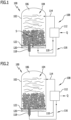
- the Fig. 1 and Fig. 2 show schematically a first embodiment of a heat storage system designated as a whole by 100.
- FIG. 1 the heat storage system during a thermal loading process
- Fig. 2 the heat storage system during a thermal discharge process.
- Such a heat storage system 100 is preferably intended for use in power plant processes, in particular solar thermal power plants, conventional power plants, storage power plants and OCR power plants, or in industrial processes, for example for storing waste heat or providing process steam.
- the heat storage system 100 comprises a storage container 102 configured to receive a storage material 104.
- the storage material 104 is provided for charging, storing, and discharging thermal energy.
- the storage container 102 forms an interior space 106 in which the storage material 104 is accommodated.
- the storage material 104 is a phase change material (PCM).
- PCM phase change material
- the storage material 104 can be any phase change material selected depending on a temperature level of a region of use of the thermal storage system 100, for example, a temperature level of a waste heat stream or the like.
- the storage material 104 can be selected for both a low-temperature and a high-temperature range.
- the storage material 104 can be, for example, water, paraffins, salt hydrates, or metals. Furthermore, the storage material 104 can be a nitrate salt or a eutectic mixture of nitrate salts and/or other salts.
- the storage material 104 in the interior 106 of the storage container 102 is present both in the liquid phase and in the solid phase.
- the ratio between storage material 104 in the liquid phase and storage material 104 in the solid phase in the storage container 102 depends on the thermal loading state of the storage material 104.
- storage material 104 in the liquid phase can collect in an upper region of the interior 106 of the storage container 102, while a bed of storage material 104 in the solid phase forms in a lower region of the interior 106 of the storage container 102.
- water or some aqueous media is selected as the storage material 104, this can also occur in reverse.
- the bed formed from the solid-phase storage material 104 has a porous structure. This allows the liquid-phase storage material 104 to flow through the solid-phase storage material 104.
- the heat storage system 100 For the removal and supply of the storage material 104 accommodated in the interior 106, the heat storage system 100 comprises a circuit 108.
- the circuit 108 has a withdrawal device 110.
- the withdrawal device 110 forms a fluid connection between the storage tank 102 and a heat transfer device 112.
- the removal device 110 is formed by a line system.
- the removal device 110 opens into the interior 106 of the storage container 102, in particular into a lower region or bottom region of the storage container 102.
- the storage material 104 is removed in the liquid phase from the storage container 102 by the removal device 110 and fed to the heat transfer device 112 for thermal discharge.
- circuit 108 comprises a supply channel/discharge channel 114 which forms a fluid connection between the heat transfer device 112 and the storage container 102.
- the supply channel/discharge channel 114 is coupled to the interior 106 of the storage container 102 via a supply/discharge opening.
- the supply/discharge opening 112 forms an access/exit to the interior 106 of the storage container 102.
- Storage material 104 in the liquid phase is supplied to and removed from the storage container 102 through the supply channel/discharge channel 114.
- the supply channel/discharge channel 114 opens into an upper region of the storage container 102 via the supply/discharge opening.
- the supply channel/discharge channel 114 opens into the interior 106 of the storage container 102 at a relatively higher position than the removal device 110.
- the circuit 108 For thermally discharging and charging the storage material 104, the circuit 108 comprises the heat transfer device 112.
- the storage material 104 supplied to the heat transfer device 112 is thermally charged or thermally discharged.
- the heat transfer device 112 is configured to transfer sensible heat.
- storage material 104 in the liquid phase is removed from the storage container 102 by the removal device 110 at a low temperature level and fed to the heat transfer device 112.
- the storage material 104 is heated to a higher temperature level in the heat transfer device 112.
- the storage material 104 does not undergo a phase change, i.e., it remains in the liquid phase. After heating the storage material 104 in the heat transfer device 112, the heated storage material 104 is fed to the storage container 102 via the supply/discharge channel 114.
- thermocline storage system Particularly in the upper region of the storage tank 102, a temperature stratification is formed by the addition of the heated storage material 104 in the liquid phase.
- the heat storage system 100 can therefore also be referred to as a thermocline storage system.
- the heat transfer device 112 is configured to transfer latent heat.
- Fig. 2 shows the heat storage system 100 during thermal discharge.
- the heat transfer device 112 is designed as a latent heat exchanger.
- the storage material 104 is fed in the liquid phase to the heat transfer device 112 via the supply channel/discharge channel 114. During thermal discharging, the storage material 104 undergoes a phase change from the liquid phase to the solid phase, releasing latent heat Q.
- the heat transfer device 112 is designed, in particular, as an active latent heat exchanger.
- the active latent heat exchanger may have a discharge device (not shown in detail), for example, a scraping device, for discharging storage material 104 solidified by the phase change from the heat transfer device 112.
- the heat transfer device 112 is designed as a rotating drum heat exchanger.
- the solidified storage material 104 is discharged from the heat transfer device 112 as a piece or as granules.
- the shape of the solidified storage material 104 can vary depending on the phase-change material.
- the circuit 108 comprises a return device 116.
- the return device 116 is configured to return the solidified storage material 104 to the interior 106 of the storage container 102 after thermal discharge by releasing latent heat in the solid phase.
- the return device 116 forms a connection for returning the solidified storage material 104 from the heat transfer device 112 to the storage container 102.
- the return device 116 opens into the interior 106 of the storage container 102.
- the return device 116 comprises a conveying unit 118 for conveying the solidified storage material 104 from the heat transfer device 112 into the interior 104 of the storage container 102.
- the conveyor unit 118 is preferably designed as a continuous conveyor.
- the conveyor unit 118 can be designed as a conveyor screw, as in Fig. 1 shown, a conveyor belt, a rotary valve or the like.
- the return device 116 may have a lock for supplying the solidified storage material 104 into the interior 104 of the storage container 102.
- the return device 116 may have a gravity feed that opens into the interior 106 of the storage tank 102.
- This gravity feed may, for example, be designed in the form of a downpipe or a separate return area in the storage tank 102.
- the solidified storage material 104 can be fed to the gravity feed, for example, from above or from the side, so that the storage material 104 is guided into the interior 106 of the storage container 102 under the influence of gravity.
- a screw conveyor can be provided, which is arranged entirely in the interior 106 of the storage container 102 and serves to distribute the solidified storage material 104 in the lower region of the storage container 102.
- a collection area 120 is formed for collecting storage material 104 in the liquid phase.
- the collection area 120 is provided in a lowermost area in the interior 106 of the storage container 102.
- an electrical and/or thermal heating device is arranged in the collection area 120 and/or adjacent to the collection area 120. This can, in particular, ensure the presence of a liquid phase.
- the collection region 120 may extend partially along a peripheral region or a peripheral wall of the storage container 102.
- the collection area 120 is separated from the remaining interior 106 of the storage container 102 by a liquid-permeable and solid-impermeable separating device 122.
- the separating device 122 is designed as a perforated plate or a sieve.
- the separating device 122 allows storage material 104 in the liquid phase to flow into the collection area 120 and prevents the storage material 104 in the solid phase from entering the collection area 120.
- the collection area 120 is fluidly coupled to the removal device 110. As a result, storage material 104 in the liquid phase can be removed from the collection area 120 by the removal device 110 and fed to the heat transfer device 112.
- storage material 104 in the liquid phase is removed from the collection region 120 at a temperature level slightly above the melting temperature or phase change temperature.
- a temperature gradient is established from a maximum temperature of the thermally loaded storage material 104 up to the melting temperature of the storage material 104 at the phase boundary.
- a constant temperature is formed at the melting temperature or phase change temperature of the storage material 104.
- the storage material 104 in the liquid phase By flowing the storage material 104 in the liquid phase through the porous bed of storage material 104 in the solid phase, it is provided that the storage material 104 in the liquid phase releases heat to the storage material 104 in the solid phase and at least partially melts it.
- the melting process of the storage material 104 in the solid phase can take place mainly near the phase boundary between the solid phase and the liquid phase.
- the removed storage material 104 in the liquid phase is then fed to the heat transfer device 112 and heated by supplying heat Q.
- the heat Q can be supplied by a heat exchanger, for example, powered by waste heat, or by a heating device, for example, an electric heater. Furthermore, the heat Q can be supplied by a high-temperature heat pump.
- the storage material 104 is heated to a temperature level significantly above the phase change temperature.
- the storage material 104 is heated to a temperature level slightly below the decomposition temperature of the storage material 104.
- the heated storage material 104 in the liquid phase is then fed back into the interior 106 of the storage container 102 via the feed channel/discharge channel 114.
- Fig. 2 shows a thermal discharge process through the heat storage system 100.
- the storage material 104 in the liquid phase is removed from the upper region in the interior 106 of the storage container 102 via the feed channel/discharge channel 114 and fed to the heat transfer device 112.
- the thermal discharge of the storage material 104 in the active latent heat exchanger takes place with the release of sensible and latent heat Q.
- the storage material 104 solidifies due to the phase change from the liquid phase to the solid phase.
- the solidified storage material 104 is present in lumps or in the form of loose granules due to the active latent heat exchanger, for example due to the discharge device, a scraping device or the rotating drum heat exchanger.
- This lumpy or granular solidified storage material 104 is subsequently fed to the return device 116, which returns the solidified storage material 104 through the conveyor unit 118 into the interior 106 of the storage container 102.
- the solidified storage material 104 is returned by the return device 116 into the lower region of the interior 106 of the storage container 102.
- the porous bed of storage material 104 is formed in the solid phase.
- the returned solidified storage material 104 is melted again by flowing through it with storage material 104 in the liquid phase.
- FIG. 3 shows the heat storage system 100 during a thermal loading process
- Fig. 4 the heat storage system 100 during a thermal discharge process.
- This alternative embodiment of the heat storage system 100 differs from the previously described first embodiment essentially in the design of the collection area 120.
- the underlying process concept of the thermal discharging and charging corresponds to that of the first embodiment of the heat storage system 100.
- the collecting area 120 is formed by a collecting channel 124.
- the collection area 120 can be formed by one collection channel 124 or by several collection channels 124 that are distributed in the interior 106 of the storage container 102.
- the collection channel 124 extends in a substantially vertical direction within the interior 106 of the storage container 102. Preferably, the collection channel 124 extends continuously from a bottom of the storage container 102 to a lid of the storage container 102.
- the collecting channel 124 can be formed, for example, by a tubular element.
- a wall of the collection channel 124 forms the liquid-permeable and solid-impermeable separating device 122 for separating the collection area 120 from the remaining interior 106 of the storage container 102.
- the separating device 122 can, for example, be formed by a plurality of passages or holes along a longitudinal extent in the wall of the collecting channel 124. Likewise, the separating device 122 can be formed by a tubular sieve.
- a lowermost section of the collecting channel 124 is fluidly connected to the removal device 110 so that storage material 104 in the liquid phase can be supplied to the heat transfer device 112 for thermal charging.
- the collecting channel 124 has a level control device 126.
- the level control device 126 blocks a flow path formed by the collecting channel 124 to the removal device 110 depending on the stratification temperature of the storage material 104. This prevents the storage material 104 in the liquid phase from flowing at a high temperature level from the uppermost region of the interior space 106 through the collecting channel 124.
- the level control device 126 comprises a height adjustment element 128 which is arranged within the collecting channel 124 so as to be height adjustable along a height adjustment direction H and blocks the flow path.
- the height adjustment element 128 can be actively driven in order to be arranged in a corresponding height position depending on the stratification temperature of the storage material 104.
- the height adjustment element 128 is constantly arranged substantially at the level of the boundary between the solid phase and the liquid phase of the storage material 104.
- the height adjustment element 128 can be designed as a passive element which automatically arranges itself in the corresponding height position as a function of the stratification temperature of the storage material 104 by a change in density or the like.
- the collecting channel 124 can be designed to be height-adjustable.
- An upper end of the collecting channel 124 can be arranged at different height positions in the interior 106 of the storage container 102 in the height adjustment direction H in order to prevent the storage material 104 in the liquid phase from flowing at the high temperature level from the uppermost region of the interior 106 through the collecting channel 124.
- the height adjustment can be achieved by means of telescopic tubes inserted into one another or by means of two twisting coaxial tubes.
- the level control device 126 When removing storage material 104 in the liquid phase, the level control device 126 ensures that liquid storage material 104 in the region of the boundary between the solid phase and the liquid phase, i.e. at a relatively lower temperature level, first flows through an upper region of the porous bed of storage material in the solid phase and then collects in the collecting channel 124.
- the storage material 104 in the solid phase is at least partially melted.
- the Fig. 4 The thermal discharge process of the heat storage system 100 shown takes place in the same way as the one described above according to Fig. 2 described discharge process.
Landscapes
- Engineering & Computer Science (AREA)
- Physics & Mathematics (AREA)
- Thermal Sciences (AREA)
- Mechanical Engineering (AREA)
- General Engineering & Computer Science (AREA)
- Other Air-Conditioning Systems (AREA)
- Central Heating Systems (AREA)
Applications Claiming Priority (2)
| Application Number | Priority Date | Filing Date | Title |
|---|---|---|---|
| DE102021210947.0A DE102021210947A1 (de) | 2021-09-30 | 2021-09-30 | Wärmespeichersystem und Verfahren zum Speichern thermischer Energie |
| PCT/EP2022/075990 WO2023052176A1 (de) | 2021-09-30 | 2022-09-19 | Wärmespeichersystem und verfahren zum speichern thermischer energie |
Publications (3)
| Publication Number | Publication Date |
|---|---|
| EP4409216A1 EP4409216A1 (de) | 2024-08-07 |
| EP4409216B1 true EP4409216B1 (de) | 2025-06-18 |
| EP4409216C0 EP4409216C0 (de) | 2025-06-18 |
Family
ID=83448005
Family Applications (1)
| Application Number | Title | Priority Date | Filing Date |
|---|---|---|---|
| EP22777242.3A Active EP4409216B1 (de) | 2021-09-30 | 2022-09-19 | Wärmespeichersystem und verfahren zum speichern thermischer energie |
Country Status (4)
| Country | Link |
|---|---|
| EP (1) | EP4409216B1 (es) |
| DE (1) | DE102021210947A1 (es) |
| ES (1) | ES3040569T3 (es) |
| WO (1) | WO2023052176A1 (es) |
Families Citing this family (2)
| Publication number | Priority date | Publication date | Assignee | Title |
|---|---|---|---|---|
| DE102024100401A1 (de) * | 2024-01-09 | 2025-07-10 | Deutsches Zentrum für Luft- und Raumfahrt e.V. | Wärmetauschervorrichtung, Verfahren zum Betreiben einer Wärmetauschervorrichtung und Verwendung einer Wärmetauschervorrichtung |
| AT528193B1 (de) * | 2024-08-07 | 2025-11-15 | Univ Wien Tech | Thermische Energiespeichervorrichtung |
Family Cites Families (6)
| Publication number | Priority date | Publication date | Assignee | Title |
|---|---|---|---|---|
| US4286141A (en) * | 1978-06-22 | 1981-08-25 | Calmac Manufacturing Corporation | Thermal storage method and system utilizing an anhydrous sodium sulfate pebble bed providing high-temperature capability |
| ATE162617T1 (de) | 1993-12-09 | 1998-02-15 | Schuemann Sasol Gmbh & Co Kg | Latentwärmespeicher |
| DE20302591U1 (de) * | 2002-12-10 | 2003-10-30 | Leidig, Karl, 85737 Ismaning | Kombi-Wärme-Kälte-Latentschichtenspeicher nach dem Kugelreaktor-Prinzip mit Schüttverfahren Befüllung |
| DE102010028676A1 (de) | 2010-05-06 | 2011-11-10 | Deutsches Zentrum für Luft- und Raumfahrt e.V. | Verfahren zur Aufnahme, Abgabe und Speicherung von Wärme sowie Latentwärmespeicher zur Anwendung des Verfahrens |
| DE102014103108A1 (de) * | 2014-03-03 | 2015-09-03 | Sven Kunkel | Latentwärmespeicher |
| DE102019210703B4 (de) | 2019-07-19 | 2026-02-19 | Deutsches Zentrum für Luft- und Raumfahrt e.V. | Wärmespeichersystem und Verfahren zum Speichern von Wärme |
-
2021
- 2021-09-30 DE DE102021210947.0A patent/DE102021210947A1/de active Pending
-
2022
- 2022-09-19 ES ES22777242T patent/ES3040569T3/es active Active
- 2022-09-19 EP EP22777242.3A patent/EP4409216B1/de active Active
- 2022-09-19 WO PCT/EP2022/075990 patent/WO2023052176A1/de not_active Ceased
Also Published As
| Publication number | Publication date |
|---|---|
| DE102021210947A1 (de) | 2023-03-30 |
| WO2023052176A1 (de) | 2023-04-06 |
| EP4409216C0 (de) | 2025-06-18 |
| ES3040569T3 (en) | 2025-11-03 |
| EP4409216A1 (de) | 2024-08-07 |
Similar Documents
| Publication | Publication Date | Title |
|---|---|---|
| EP4409216B1 (de) | Wärmespeichersystem und verfahren zum speichern thermischer energie | |
| DE2748635C2 (de) | Wärmespeicher | |
| DE2916514C2 (de) | Verfahren zur Verbesserung des Wärmeaustausches in einem Latentwärmespeicher sowie Vorrichtung zur Durchführung des Verfahrens | |
| DE69400918T2 (de) | Vorrichtung zur durchführung von physikalischen und/oder chemischen verfahren, zum beispiel ein wärmetauscher | |
| DE2607168A1 (de) | Verfahren und vorrichtung zum austauschen von waerme | |
| EP0614688B1 (de) | Vorrichtung zur Erzeugung von Kristallkeimen in Schmelzen und eine derartige Vorrichtung enthaltende Kristallisationsanlage | |
| CH636427A5 (de) | Verfahren zur ladung und entladung eines latentwaerme-speichermediums und waermespeicher. | |
| DE2622631C3 (de) | Verfahren zum Betreiben eines Wärmetauschers und Wärmetauscher mit einem System von ein Granulat enthaltenden lotrechten Röhren | |
| DE102007009759A1 (de) | Verfahren und Vorrichtung zur Aufteilung eines Feststoffstromes | |
| DE102011053349B4 (de) | Wärmespeichersystem und Verfahren zum Speichern von Wärme | |
| EP0518369B1 (de) | Schichtspeicher | |
| DE3536958C1 (de) | Verfahren und Vorrichtung zur Vorwaermung von Verbrennungsluft und zur katalytischenReduktion von Schadstoffen in Rauchgas | |
| WO1995016176A1 (de) | Latentwärmespeicher | |
| DE102010028676A1 (de) | Verfahren zur Aufnahme, Abgabe und Speicherung von Wärme sowie Latentwärmespeicher zur Anwendung des Verfahrens | |
| DE102012000143A1 (de) | Verfahren und Vorrichtung zur Wärmeübertragung und Wärmespeicherung unter Nutzung des spezifischen und latenten Wärmeinhaltes von Stoffen | |
| EP0006219B1 (de) | Verfahren und Vorrichtung zur Speicherung von Wärmeenergie | |
| DE3049683A1 (en) | Apparatus for producing sludge | |
| DE102019210703B4 (de) | Wärmespeichersystem und Verfahren zum Speichern von Wärme | |
| DE102019207965B4 (de) | Wärmespeichervorrichtung und Verfahren zum Speichern und/oder Bereitstellen von Wärme | |
| DE29512743U1 (de) | Latentwärmespeicher | |
| CH663178A5 (de) | Verfahren zur rueckfuehrung von thermoplastfolienabfall, vorrichtung zur durchfuehrung des verfahrens und extruder mit einer solchen vorrichtung. | |
| DE102016202285A1 (de) | Wärmeübertragungsvorrichtung und Verfahren zum Übertragen von Wärme | |
| DE2745492C3 (es) | ||
| DE2729094B2 (de) | Einrichtung zur Gewinnung von kunstlichem Fischrogen aus Lösungen oder Suspensionen von Eiweißstoffen | |
| DE29821270U1 (de) | Vorrichtung zum Speichern von latenter Wärme mittels eines Speichermediums |
Legal Events
| Date | Code | Title | Description |
|---|---|---|---|
| STAA | Information on the status of an ep patent application or granted ep patent |
Free format text: STATUS: UNKNOWN |
|
| STAA | Information on the status of an ep patent application or granted ep patent |
Free format text: STATUS: THE INTERNATIONAL PUBLICATION HAS BEEN MADE |
|
| PUAI | Public reference made under article 153(3) epc to a published international application that has entered the european phase |
Free format text: ORIGINAL CODE: 0009012 |
|
| STAA | Information on the status of an ep patent application or granted ep patent |
Free format text: STATUS: REQUEST FOR EXAMINATION WAS MADE |
|
| 17P | Request for examination filed |
Effective date: 20240327 |
|
| AK | Designated contracting states |
Kind code of ref document: A1 Designated state(s): AL AT BE BG CH CY CZ DE DK EE ES FI FR GB GR HR HU IE IS IT LI LT LU LV MC MK MT NL NO PL PT RO RS SE SI SK SM TR |
|
| DAV | Request for validation of the european patent (deleted) | ||
| DAX | Request for extension of the european patent (deleted) | ||
| GRAP | Despatch of communication of intention to grant a patent |
Free format text: ORIGINAL CODE: EPIDOSNIGR1 |
|
| STAA | Information on the status of an ep patent application or granted ep patent |
Free format text: STATUS: GRANT OF PATENT IS INTENDED |
|
| INTG | Intention to grant announced |
Effective date: 20250122 |
|
| GRAS | Grant fee paid |
Free format text: ORIGINAL CODE: EPIDOSNIGR3 |
|
| GRAA | (expected) grant |
Free format text: ORIGINAL CODE: 0009210 |
|
| STAA | Information on the status of an ep patent application or granted ep patent |
Free format text: STATUS: THE PATENT HAS BEEN GRANTED |
|
| AK | Designated contracting states |
Kind code of ref document: B1 Designated state(s): AL AT BE BG CH CY CZ DE DK EE ES FI FR GB GR HR HU IE IS IT LI LT LU LV MC MK MT NL NO PL PT RO RS SE SI SK SM TR |
|
| REG | Reference to a national code |
Ref country code: GB Ref legal event code: FG4D Free format text: NOT ENGLISH |
|
| REG | Reference to a national code |
Ref country code: CH Ref legal event code: EP |
|
| REG | Reference to a national code |
Ref country code: DE Ref legal event code: R096 Ref document number: 502022004358 Country of ref document: DE |
|
| REG | Reference to a national code |
Ref country code: CH Ref legal event code: EP |
|
| REG | Reference to a national code |
Ref country code: IE Ref legal event code: FG4D Free format text: LANGUAGE OF EP DOCUMENT: GERMAN |
|
| U01 | Request for unitary effect filed |
Effective date: 20250715 |
|
| U07 | Unitary effect registered |
Designated state(s): AT BE BG DE DK EE FI FR IT LT LU LV MT NL PT RO SE SI Effective date: 20250721 |
|
| PG25 | Lapsed in a contracting state [announced via postgrant information from national office to epo] |
Ref country code: NO Free format text: LAPSE BECAUSE OF FAILURE TO SUBMIT A TRANSLATION OF THE DESCRIPTION OR TO PAY THE FEE WITHIN THE PRESCRIBED TIME-LIMIT Effective date: 20250918 Ref country code: GR Free format text: LAPSE BECAUSE OF FAILURE TO SUBMIT A TRANSLATION OF THE DESCRIPTION OR TO PAY THE FEE WITHIN THE PRESCRIBED TIME-LIMIT Effective date: 20250919 |
|
| PG25 | Lapsed in a contracting state [announced via postgrant information from national office to epo] |
Ref country code: HR Free format text: LAPSE BECAUSE OF FAILURE TO SUBMIT A TRANSLATION OF THE DESCRIPTION OR TO PAY THE FEE WITHIN THE PRESCRIBED TIME-LIMIT Effective date: 20250618 |
|
| PG25 | Lapsed in a contracting state [announced via postgrant information from national office to epo] |
Ref country code: RS Free format text: LAPSE BECAUSE OF FAILURE TO SUBMIT A TRANSLATION OF THE DESCRIPTION OR TO PAY THE FEE WITHIN THE PRESCRIBED TIME-LIMIT Effective date: 20250918 |
|
| U20 | Renewal fee for the european patent with unitary effect paid |
Year of fee payment: 4 Effective date: 20250923 |
|
| REG | Reference to a national code |
Ref country code: ES Ref legal event code: FG2A Ref document number: 3040569 Country of ref document: ES Kind code of ref document: T3 Effective date: 20251103 |
|
| PG25 | Lapsed in a contracting state [announced via postgrant information from national office to epo] |
Ref country code: IS Free format text: LAPSE BECAUSE OF FAILURE TO SUBMIT A TRANSLATION OF THE DESCRIPTION OR TO PAY THE FEE WITHIN THE PRESCRIBED TIME-LIMIT Effective date: 20251018 |
|
| PG25 | Lapsed in a contracting state [announced via postgrant information from national office to epo] |
Ref country code: SM Free format text: LAPSE BECAUSE OF FAILURE TO SUBMIT A TRANSLATION OF THE DESCRIPTION OR TO PAY THE FEE WITHIN THE PRESCRIBED TIME-LIMIT Effective date: 20250618 |
|
| PG25 | Lapsed in a contracting state [announced via postgrant information from national office to epo] |
Ref country code: CZ Free format text: LAPSE BECAUSE OF FAILURE TO SUBMIT A TRANSLATION OF THE DESCRIPTION OR TO PAY THE FEE WITHIN THE PRESCRIBED TIME-LIMIT Effective date: 20250618 |
|
| PG25 | Lapsed in a contracting state [announced via postgrant information from national office to epo] |
Ref country code: PL Free format text: LAPSE BECAUSE OF FAILURE TO SUBMIT A TRANSLATION OF THE DESCRIPTION OR TO PAY THE FEE WITHIN THE PRESCRIBED TIME-LIMIT Effective date: 20250618 |
|
| PG25 | Lapsed in a contracting state [announced via postgrant information from national office to epo] |
Ref country code: SK Free format text: LAPSE BECAUSE OF FAILURE TO SUBMIT A TRANSLATION OF THE DESCRIPTION OR TO PAY THE FEE WITHIN THE PRESCRIBED TIME-LIMIT Effective date: 20250618 |
|
| PGFP | Annual fee paid to national office [announced via postgrant information from national office to epo] |
Ref country code: ES Payment date: 20251020 Year of fee payment: 4 |
|
| PLBE | No opposition filed within time limit |
Free format text: ORIGINAL CODE: 0009261 |
|
| STAA | Information on the status of an ep patent application or granted ep patent |
Free format text: STATUS: NO OPPOSITION FILED WITHIN TIME LIMIT |