EP4409138B1 - Dichtungsvorrichtung für eine kolbenstange eines hubkolbenverdichters - Google Patents
Dichtungsvorrichtung für eine kolbenstange eines hubkolbenverdichters Download PDFInfo
- Publication number
- EP4409138B1 EP4409138B1 EP23808717.5A EP23808717A EP4409138B1 EP 4409138 B1 EP4409138 B1 EP 4409138B1 EP 23808717 A EP23808717 A EP 23808717A EP 4409138 B1 EP4409138 B1 EP 4409138B1
- Authority
- EP
- European Patent Office
- Prior art keywords
- packing ring
- packing
- axial
- sealing device
- compressor
- Prior art date
- Legal status (The legal status is an assumption and is not a legal conclusion. Google has not performed a legal analysis and makes no representation as to the accuracy of the status listed.)
- Active
Links
Images


Classifications
-
- F—MECHANICAL ENGINEERING; LIGHTING; HEATING; WEAPONS; BLASTING
- F04—POSITIVE - DISPLACEMENT MACHINES FOR LIQUIDS; PUMPS FOR LIQUIDS OR ELASTIC FLUIDS
- F04B—POSITIVE-DISPLACEMENT MACHINES FOR LIQUIDS; PUMPS
- F04B19/00—Machines or pumps having pertinent characteristics not provided for in, or of interest apart from, groups F04B1/00 - F04B17/00
- F04B19/20—Other positive-displacement pumps
- F04B19/22—Other positive-displacement pumps of reciprocating-piston type
-
- F—MECHANICAL ENGINEERING; LIGHTING; HEATING; WEAPONS; BLASTING
- F16—ENGINEERING ELEMENTS AND UNITS; GENERAL MEASURES FOR PRODUCING AND MAINTAINING EFFECTIVE FUNCTIONING OF MACHINES OR INSTALLATIONS; THERMAL INSULATION IN GENERAL
- F16J—PISTONS; CYLINDERS; SEALINGS
- F16J15/00—Sealings
- F16J15/46—Sealings with packing ring expanded or pressed into place by fluid pressure, e.g. inflatable packings
-
- F—MECHANICAL ENGINEERING; LIGHTING; HEATING; WEAPONS; BLASTING
- F04—POSITIVE - DISPLACEMENT MACHINES FOR LIQUIDS; PUMPS FOR LIQUIDS OR ELASTIC FLUIDS
- F04B—POSITIVE-DISPLACEMENT MACHINES FOR LIQUIDS; PUMPS
- F04B39/00—Component parts, details, or accessories, of pumps or pumping systems specially adapted for elastic fluids, not otherwise provided for in, or of interest apart from, groups F04B25/00 - F04B37/00
- F04B39/0005—Component parts, details, or accessories, of pumps or pumping systems specially adapted for elastic fluids, not otherwise provided for in, or of interest apart from, groups F04B25/00 - F04B37/00 adaptations of pistons
- F04B39/0022—Component parts, details, or accessories, of pumps or pumping systems specially adapted for elastic fluids, not otherwise provided for in, or of interest apart from, groups F04B25/00 - F04B37/00 adaptations of pistons piston rods
-
- F—MECHANICAL ENGINEERING; LIGHTING; HEATING; WEAPONS; BLASTING
- F04—POSITIVE - DISPLACEMENT MACHINES FOR LIQUIDS; PUMPS FOR LIQUIDS OR ELASTIC FLUIDS
- F04B—POSITIVE-DISPLACEMENT MACHINES FOR LIQUIDS; PUMPS
- F04B39/00—Component parts, details, or accessories, of pumps or pumping systems specially adapted for elastic fluids, not otherwise provided for in, or of interest apart from, groups F04B25/00 - F04B37/00
- F04B39/04—Measures to avoid lubricant contaminating the pumped fluid
- F04B39/041—Measures to avoid lubricant contaminating the pumped fluid sealing for a reciprocating rod
-
- F—MECHANICAL ENGINEERING; LIGHTING; HEATING; WEAPONS; BLASTING
- F04—POSITIVE - DISPLACEMENT MACHINES FOR LIQUIDS; PUMPS FOR LIQUIDS OR ELASTIC FLUIDS
- F04B—POSITIVE-DISPLACEMENT MACHINES FOR LIQUIDS; PUMPS
- F04B49/00—Control, e.g. of pump delivery, or pump pressure of, or safety measures for, machines, pumps, or pumping installations, not otherwise provided for, or of interest apart from, groups F04B1/00 - F04B47/00
-
- F—MECHANICAL ENGINEERING; LIGHTING; HEATING; WEAPONS; BLASTING
- F04—POSITIVE - DISPLACEMENT MACHINES FOR LIQUIDS; PUMPS FOR LIQUIDS OR ELASTIC FLUIDS
- F04B—POSITIVE-DISPLACEMENT MACHINES FOR LIQUIDS; PUMPS
- F04B5/00—Machines or pumps with differential-surface pistons
- F04B5/02—Machines or pumps with differential-surface pistons with double-acting pistons
-
- F—MECHANICAL ENGINEERING; LIGHTING; HEATING; WEAPONS; BLASTING
- F04—POSITIVE - DISPLACEMENT MACHINES FOR LIQUIDS; PUMPS FOR LIQUIDS OR ELASTIC FLUIDS
- F04B—POSITIVE-DISPLACEMENT MACHINES FOR LIQUIDS; PUMPS
- F04B53/00—Component parts, details or accessories not provided for in, or of interest apart from, groups F04B1/00 - F04B23/00 or F04B39/00 - F04B47/00
- F04B53/14—Pistons, piston-rods or piston-rod connections
- F04B53/144—Adaptation of piston-rods
- F04B53/146—Piston-rod guiding arrangements
-
- F—MECHANICAL ENGINEERING; LIGHTING; HEATING; WEAPONS; BLASTING
- F16—ENGINEERING ELEMENTS AND UNITS; GENERAL MEASURES FOR PRODUCING AND MAINTAINING EFFECTIVE FUNCTIONING OF MACHINES OR INSTALLATIONS; THERMAL INSULATION IN GENERAL
- F16J—PISTONS; CYLINDERS; SEALINGS
- F16J15/00—Sealings
- F16J15/002—Sealings comprising at least two sealings in succession
- F16J15/004—Sealings comprising at least two sealings in succession forming of recuperation chamber for the leaking fluid
-
- F—MECHANICAL ENGINEERING; LIGHTING; HEATING; WEAPONS; BLASTING
- F16—ENGINEERING ELEMENTS AND UNITS; GENERAL MEASURES FOR PRODUCING AND MAINTAINING EFFECTIVE FUNCTIONING OF MACHINES OR INSTALLATIONS; THERMAL INSULATION IN GENERAL
- F16J—PISTONS; CYLINDERS; SEALINGS
- F16J15/00—Sealings
- F16J15/002—Sealings comprising at least two sealings in succession
- F16J15/008—Sealings comprising at least two sealings in succession with provision to put out of action at least one sealing; One sealing sealing only on standstill; Emergency or servicing sealings
-
- F—MECHANICAL ENGINEERING; LIGHTING; HEATING; WEAPONS; BLASTING
- F16—ENGINEERING ELEMENTS AND UNITS; GENERAL MEASURES FOR PRODUCING AND MAINTAINING EFFECTIVE FUNCTIONING OF MACHINES OR INSTALLATIONS; THERMAL INSULATION IN GENERAL
- F16J—PISTONS; CYLINDERS; SEALINGS
- F16J15/00—Sealings
- F16J15/16—Sealings between relatively-moving surfaces
- F16J15/164—Sealings between relatively-moving surfaces the sealing action depending on movements; pressure difference, temperature or presence of leaking fluid
-
- F—MECHANICAL ENGINEERING; LIGHTING; HEATING; WEAPONS; BLASTING
- F16—ENGINEERING ELEMENTS AND UNITS; GENERAL MEASURES FOR PRODUCING AND MAINTAINING EFFECTIVE FUNCTIONING OF MACHINES OR INSTALLATIONS; THERMAL INSULATION IN GENERAL
- F16J—PISTONS; CYLINDERS; SEALINGS
- F16J15/00—Sealings
- F16J15/16—Sealings between relatively-moving surfaces
- F16J15/18—Sealings between relatively-moving surfaces with stuffing-boxes for elastic or plastic packings
- F16J15/181—Sealings between relatively-moving surfaces with stuffing-boxes for elastic or plastic packings for plastic packings
-
- F—MECHANICAL ENGINEERING; LIGHTING; HEATING; WEAPONS; BLASTING
- F16—ENGINEERING ELEMENTS AND UNITS; GENERAL MEASURES FOR PRODUCING AND MAINTAINING EFFECTIVE FUNCTIONING OF MACHINES OR INSTALLATIONS; THERMAL INSULATION IN GENERAL
- F16J—PISTONS; CYLINDERS; SEALINGS
- F16J15/00—Sealings
- F16J15/16—Sealings between relatively-moving surfaces
- F16J15/18—Sealings between relatively-moving surfaces with stuffing-boxes for elastic or plastic packings
- F16J15/182—Sealings between relatively-moving surfaces with stuffing-boxes for elastic or plastic packings with lubricating, cooling or draining means
-
- F—MECHANICAL ENGINEERING; LIGHTING; HEATING; WEAPONS; BLASTING
- F16—ENGINEERING ELEMENTS AND UNITS; GENERAL MEASURES FOR PRODUCING AND MAINTAINING EFFECTIVE FUNCTIONING OF MACHINES OR INSTALLATIONS; THERMAL INSULATION IN GENERAL
- F16J—PISTONS; CYLINDERS; SEALINGS
- F16J15/00—Sealings
- F16J15/16—Sealings between relatively-moving surfaces
- F16J15/18—Sealings between relatively-moving surfaces with stuffing-boxes for elastic or plastic packings
- F16J15/188—Split assemblies
-
- F—MECHANICAL ENGINEERING; LIGHTING; HEATING; WEAPONS; BLASTING
- F16—ENGINEERING ELEMENTS AND UNITS; GENERAL MEASURES FOR PRODUCING AND MAINTAINING EFFECTIVE FUNCTIONING OF MACHINES OR INSTALLATIONS; THERMAL INSULATION IN GENERAL
- F16J—PISTONS; CYLINDERS; SEALINGS
- F16J15/00—Sealings
- F16J15/16—Sealings between relatively-moving surfaces
- F16J15/18—Sealings between relatively-moving surfaces with stuffing-boxes for elastic or plastic packings
- F16J15/20—Packing materials therefor
-
- F—MECHANICAL ENGINEERING; LIGHTING; HEATING; WEAPONS; BLASTING
- F16—ENGINEERING ELEMENTS AND UNITS; GENERAL MEASURES FOR PRODUCING AND MAINTAINING EFFECTIVE FUNCTIONING OF MACHINES OR INSTALLATIONS; THERMAL INSULATION IN GENERAL
- F16J—PISTONS; CYLINDERS; SEALINGS
- F16J15/00—Sealings
- F16J15/16—Sealings between relatively-moving surfaces
- F16J15/26—Sealings between relatively-moving surfaces with stuffing-boxes for rigid sealing rings
-
- F—MECHANICAL ENGINEERING; LIGHTING; HEATING; WEAPONS; BLASTING
- F16—ENGINEERING ELEMENTS AND UNITS; GENERAL MEASURES FOR PRODUCING AND MAINTAINING EFFECTIVE FUNCTIONING OF MACHINES OR INSTALLATIONS; THERMAL INSULATION IN GENERAL
- F16J—PISTONS; CYLINDERS; SEALINGS
- F16J15/00—Sealings
- F16J15/16—Sealings between relatively-moving surfaces
- F16J15/32—Sealings between relatively-moving surfaces with elastic sealings, e.g. O-rings
- F16J15/3204—Sealings between relatively-moving surfaces with elastic sealings, e.g. O-rings with at least one lip
- F16J15/3232—Sealings between relatively-moving surfaces with elastic sealings, e.g. O-rings with at least one lip having two or more lips
- F16J15/3236—Sealings between relatively-moving surfaces with elastic sealings, e.g. O-rings with at least one lip having two or more lips with at least one lip for each surface, e.g. U-cup packings
-
- F—MECHANICAL ENGINEERING; LIGHTING; HEATING; WEAPONS; BLASTING
- F16—ENGINEERING ELEMENTS AND UNITS; GENERAL MEASURES FOR PRODUCING AND MAINTAINING EFFECTIVE FUNCTIONING OF MACHINES OR INSTALLATIONS; THERMAL INSULATION IN GENERAL
- F16J—PISTONS; CYLINDERS; SEALINGS
- F16J15/00—Sealings
- F16J15/16—Sealings between relatively-moving surfaces
- F16J15/32—Sealings between relatively-moving surfaces with elastic sealings, e.g. O-rings
- F16J15/3248—Sealings between relatively-moving surfaces with elastic sealings, e.g. O-rings provided with casings or supports
- F16J15/3252—Sealings between relatively-moving surfaces with elastic sealings, e.g. O-rings provided with casings or supports with rigid casings or supports
Definitions
- the invention relates to sealing device for sealing a piston rod of a reciprocating compressor, the sealing device comprising a first axial device end, configured to face toward a cylinder of the compressor, and an opposite second axial device end, configured to face toward a crankcase of the compressor, a number of first packing retainers, each retainer including a retaining opening in which a first packing ring is arranged, a second packing retainer, including a retaining opening in which a second packing ring is arranged, the second retainer being positioned closer to the second axial end than the number of first packing retainers in an axial direction of the sealing device, wherein the second packing ring is an uncut ring, comprising a continuous inner circumferential sealing surface.
- the invention further relates to a reciprocating compressor including such a sealing device as well to a method for operating such a piston compressor.
- sealing devices are used to seal the compression chamber in cylinder against the crank case or the distance piece respectively.
- Such sealing devices comprise a number of packing retainers, often formed in a circular plate like fashion, in each of which retainers a retaining opening as arranged.
- a packing ring is arranged, which during operation of the compressor cooperates with an outer circumferential surface of a piston rod in order to form a sealing barrier.
- the piston rod predominantly executes a reciprocating movement relative to the sealing device in an axial direction of the cylinder.
- packing rings which consist of multiple segments, are used. However, such segmented packing rings are typically activated only during operation by a differential pressure between a high pressure in the compression chamber and a low pressure in the crankcase in order to form the sealing barrier.
- segmented rings are typically (at least partially) deactivated. This is due to the fact, that, although there is still a certain differential pressure present, the sealing surfaces of the segmented rings do not conform to the outer surface of the piston rod anymore, when the piston rod cools down after shutdown. This is essentially a result of the segmented rings and the piston rod having different thermal expansions. Therefore, in the cold state, e.g., at ambient temperature, a certain gap is created between the segmented rings and the piston rod in, which gaps form a leakage passage.
- the unsegmented sealing ring needs to be made of a very soft and elastic material. Such materials however tend to wear out faster compared to rigid materials and also have lower suitability to withstand high pressures or corrosive gases.
- the opening and closing of the valve needs to be coupled to the operation mode of the compressor.
- a failure of the valve control e.g., the valve being closed during operation of the compressor, would lead to a quick wear and most likely to a destruction of the sealing ring. This would lead to an unwanted leakage of gas past the broken sealing ring and into the crankcase, since due to the closed valve no venting is possible. While the gas contained in the vent line is safely treated, e.g., sent to a burning device, the gas that accumulates in the distance piece is often untreated and might cause formation of explosive atmosphere and/or environmental damage due to release of greenhouse gas into the air.
- EP 3 330 538 A1 discloses a different approach for a standby seal.
- the stuffing box comprises an inflatable sealing ring, which is made of an expandable material and which is selectively in fluid communication with a pressurized fluid source. When inflated, the sealing ring expands and forms a seal interface with the outer surface of the rod.
- a pressurized fluid source e.g., nitrogen
- US 4,469,017 A discloses a sealing device including a special piston, which is connected to a pressure source in order to be axially moved. When activated, the piston moves a ring in the axial direction towards a flexible sealing collar. On the ring and the collar cooperating chamfers are provided, such that when the ring is moved, the collar is pressed against the piston rod by the ring in order to form a seal.
- the structure and control of the seal are very complex and an external source of energy in the form of pressurized medium is also required.
- this invention is known to be not very robust because, when the movable piston is retracted, sometimes the lip seal does not detach from the rod and therefore is irreparably damaged at compressor startup.
- the second packing ring is made from a material comprising a polymer, the material having a thermal expansion coefficient, which is at least two times higher than the thermal expansion coefficient of iron, wherein at or below a defined activation temperature an inner diameter of the second packing ring is smaller than an outer diameter of the piston rod to be sealed, such that in the mounted state of the sealing device in the compressor the second packing ring is prestressed in a radial direction in order to form a tight seal between the continuous inner circumferential sealing surface of the second packing ring and the outer circumferential surface of the piston rod, wherein at a given operating temperature, the inner diameter of the second packing ring is larger than the outer diameter of the piston rod, such that in the mounted state of the sealing device in the compressor the continuous inner circumferential sealing surface is detached from the outer circumferential surface of the piston rod in order to provide a leakage path between the inner circumferential surface of the second packing ring and the outer circumferential surface of the piston rod in the
- the thermal expansion coefficient of the material of the second packing ring is at least 30x10-6K-1, preferably at least 60x10-6 K-1, in particular at least 90x10-6 K-1.
- the region 30x10-6K-1 and above was found to provide a suitable expansion.
- the operating temperature is preferably 90°C or above and/or the activation temperature is preferably 80°C or below, wherein the operating temperature and the activation temperature are temperatures in the region of the piston rod, in particular a temperature of the outer circumferential surface the piston rod. This allows a good sealing effect at standstill and a sufficient expansion for detachment of the second packing ring from the piston rod.
- the second packing ring has a first axial end and an opposite second axial end, wherein the second packing ring is arranged in in the retaining opening of the second packing retainer, such that the first axial end faces towards the first axial device end of the sealing device and wherein the second packing ring comprises one of: a U-shaped cross section comprising an inner shank and an outer shank, which are spaced apart in the radial direction, wherein the inner circumferential sealing surface of the second packing ring is provided on the inner shank and a radially outer circumferential surface is provided on the outer shank of the second packing ring, wherein an open side of the U-shape faces toward the first axial end of the second packing ring in the axial direction; an L-shaped cross section comprising an axial shank and a radial shank, wherein the inner circumferential sealing surface of the second packing ring is provided on the axial shank and a radially outer circumferential surface of the second packing ring is provided on the axial direction; an
- a number of openings are preferably provided on the outer shank, wherein each of the number of openings connects an inside space of the U-shaped packing ring with the radially outer circumferential surface of the second packing ring, the inside space lying between the inner shank and the outer shank in the radial direction, wherein the openings are spaced from the opposite axial ends, of the second packing ring.
- the number of openings preferably comprise a number of elongated holes or elliptical holes, wherein each elongated hole or elliptical hole preferably comprises a longitudinal axis, a first hole end and an opposite second hole end in the direction of the longitudinal axis, wherein the first hole end is closer to the first ring end than the second hole end.
- a length of the inner shank in the axial direction is smaller than a length of the outer shank in the axial direction.
- the openings allow gas to flow past the second packing ring. Further, the openings give the second packing ring a certain flexibility in the axial direction. This permits a tight seat of the second packing ring in the retaining opening of the second packing retainer, essentially independent from axial thermal expansion.
- the material of the second packing ring is preferably a fiber-reinforced composite material. This enhances the mechanical strength of the second packing ring.
- the polymer of the material of the second packing ring preferably comprises at least one of: polytetrafluoroethylene, polyphenylene sulphide, polyether ether ketone, polyimide, polyamide. Those polymers provide sufficient rigidity and have favorable tribological properties.
- the sealing device further comprises a support passage having a first support passage end, a second support passage end and a valve for opening and closing the support passage, the support passage being configured to vent a gas, leaking from the first axial device end in the direction of the second device end past at least one of the number of first packing rings, from the first support passage end to the second support passage end.
- a support passage enhances the functionality during operation of the compressor. This is because a relatively large pressure drop over the second packing ring is avoided, that would occur without the provision of a support passage during operation.
- the first support passage end is connected to the retaining opening of the second packing retainer, preferably in a region radially outside of the second packing ring, or the first support passage end is located between the second packing ring and the first packing ring of the adjacent first packing retainer in an axial direction of the sealing device or the number of first packing retainers comprises at least two first packing retainers, wherein the first support passage end is located in the region of the first packing ring, which is adjacent the second packing ring or between the first packing ring, which is adjacent the second packing ring and the first sealing device end in the axial direction of the sealing device.
- the first two alternatives enhance the design flexibility and are essentially similar in function.
- the third alternative can be advantageous in two ways.
- this configuration allows the first packing ring, that is adjacent the second packing ring, to provide an additional seal during the time between a shut-off of the compressor and the activation of the second packing ring, which is delayed due to necessary time for the thermal activation.
- the pressure-drop over the first packing ring, that is adjacent the second packing ring can be used for cooling the second packing ring, which accelerates the thermal activation. In the latter, it is particularly preferable, if the respective first packing ring comprises a metal material.
- the valve comprises an electrically controllable actuator, which can be controlled by a control unit in order to open and close the valve. This allows to open and close the support passage e.g., via the compressor control unit.
- the valve further comprises a sensor configured to generate a sensor value, representative for an opening state of the valve.
- a closed control loop can be created, which allows e.g., the compressor not being started, when the valve is still closed.
- the sealing device further comprises an unobstructed vent passage having a first vent passage end and a second vent passage end, the vent passage being configured to vent a gas, leaking from the first axial device end in the direction of the second axial device end past the second packing ring, from the first vent passage end to the second vent passage end.
- the sealing device further comprises at least one third packing retainer including a retaining opening in which a third packing ring is arranged, wherein the at least one third packing retainer is arranged closer to the second axial device end of the sealing device than the second packing retainer.
- the third packing ring can further improve the safety, because an additional sealing barrier is created behind the second sealing ring.
- the first vent passage end is preferably connected to the retaining opening of the third packing retainer, preferably radially outside of the at least one third packing ring or the first vent passage end is located between the second packing ring and the third packing ring in the axial direction of the sealing device. This allows an essentially free flow of gas into the vent passage.
- the second vent passage end of the unobstructed vent passage and the second support passage end of the support passage are preferably connected to a common discharge passage, which is connectable to a discharge space, preferably to a disposal system.
- a discharge space preferably to a disposal system.
- the valve of the support passage in this case can of course only open/close the support passage, while the vent passage remains unobstructed.
- At least one sealing device according to the invention is preferably used in a reciprocating piston compressor, which comprises a number of cylinders, in each of which cylinders a piston is arranged, that is movable in a reciprocating manner.
- a reciprocating piston compressor which comprises a number of cylinders, in each of which cylinders a piston is arranged, that is movable in a reciprocating manner.
- Each piston is connected to a piston rod, wherein for at least one cylinder of the number of cylinders, the sealing device according to the invention is arranged for sealing the respective piston rod, wherein the sealing device is arranged such that the first axial device end faces towards the cylinder and the second axial device end faces towards a crankcase of the compressor.
- the compressor comprises more than one cylinder, preferably for each cylinder a sealing device according to the invention is arranged.
- the compressor preferably comprises a compressor control unit for controlling an operation of the compressor, wherein the control unit is further configured to control the electrically controllable actuator of the valve of the support passage dependent on an operation condition of the compressor. by this, the opening/closing of the valve can be coupled to the operation condition of the compressor.
- the compressor comprises an operation condition sensor, configured to detect a sensor value, representative for an operation condition of the compressor, preferably a temperature sensor or a movement sensor, wherein the electrically controllable actuator of the valve of the support passage is configured to control the valve dependent on the sensor value or wherein the control unit is configured to control the electrically controllable actuator of the valve dependent on the sensor value.
- the compressor also comprises a drive unit for driving the compressor, wherein the compressor control unit is configured to send a start signal to the drive unit for starting the operation of the compressor and to send an opening signal to the actuator of the valve of the support passage for opening the valve simultaneously with the start signal or a predetermined or adjustable opening lead time before the start signal, wherein the opening lead time is preferably in the range between 0 to 60 seconds.
- the control unit is preferably configured to send a stop signal to the drive unit for stopping the operation of the compressor and to send a closing signal to the actuator of the valve of the support passage for closing the valve simultaneously with the stop signal or after a predetermined or adjustable closing delay time after the stop signal, wherein the closing delay time is preferably in the range between 0 to 120 seconds.
- the opening/closing of the valve can be directly coupled to the starting/stopping of the drive unit.
- the object of the invention is also achieved with the method for operating a reciprocating piston compressor, the compressor comprising a number of cylinders, in each of which cylinders a piston is arranged, that is movable in a reciprocating manner, wherein each piston is connected to a piston rod, wherein for each cylinder of the number of cylinders, a sealing device for sealing the respective piston rod is provided, which device comprises a first axial device end a, facing toward the respective cylinder, and an opposite second axial device end, facing toward a crankcase of the compressor, wherein at least one sealing device of the number of sealing devices comprises a number of first packing retainers, each retainer including a retaining opening in which a first packing ring is arranged, a second packing retainer, including a retaining opening, in which a second packing ring is arranged, the second retainer being positioned closer to the second axial device end than the number of first packing retainers in an axial direction of the sealing device, wherein the second packing ring is an uncut ring, compris
- the method further comprises the following steps: stopping the operation of the compressor until standstill; cooling down the compressor until of below the activation temperature , wherein upon reaching the activation temperature the continuous inner circumferential sealing surface of the second packing ring attaches to the outer circumferential surface of the piston rod and forms a tight seal between the continuous inner circumferential sealing surface of the second packing ring and the outer circumferential surface of the piston rod.
- the at least one sealing device further comprises a support passage having a first support passage end, a second support passage end and a valve for opening and closing the support passage, the method further comprising: opening the valve of the support passage simultaneously with the starting of the operation of the compressor or an opening lead time before the start of the operation of the compressor, wherein the opening lead time is preferably set to be in the range between 0 to 60 seconds, venting a gas, leaking from the first axial device end in the direction of the second axial device end past at least one of the number of first packing rings, from the first support passage end to the second support passage end, closing the valve simultaneously with the stopping of the operation of the compressor or after an closing delay time after the stopping of the operation of the compressor, wherein the closing delay time is preferably set to be in the range between 0 to 120 seconds.
- the method further comprises: venting a gas, leaking in the axial direction from the cylinder in the direction of the crankcase past the second packing ring, through an unobstructed vent passage.
- FIG.1 an exemplary reciprocating piston compressor 1 is shown.
- the compressor 1 comprises a compressor casing, which in this example includes a crankcase 2, a distance piece 3 and a cylinder housing 4.
- the distance piece 3 is only optional and the compressor 1 could also be designed without a distance piece 3.
- a crankshaft 5 is arranged, which can rotate about an axis of rotation.
- the crankshaft 5 is connected to a connecting rod 6, which is in turn connected to a cross-head 7.
- the cross-head 7 is mounted in the crank case 2 by means of a suitable bearing, such that a cross-head 7 can perform an axial movement.
- the cross-head 7 is connected to a piston rod 8, which extends through the distance piece 3 and into a cylinder, 9 which is arranged in the cylinder housing 4.
- a piston 10 is arranged, which is connected to the piston rod 8.
- the depicted compressor 1 is designed as a single cylinder compressor. However, the compressor 1 can of course also comprise multiple cylinders 9, in each of which cylinders 9, a piston is arranged, that is connected to the common crankshaft 5 by means of a piston rod 8. For the sake of simplicity, the invention is described in connection with one cylinder 9 only.
- the compressor 1 is designed as a double acting compressor, wherein the piston divides the cylinder 9 into a first compression chamber 11a facing away from the crankshaft 5 and a second compression chamber 11b facing towards the crankshaft 5.
- the first compression chamber 11a is closed in the axial direction by means of a first cylinder head 12a and the second compression chamber 11b is closed in the axial direction by means of a second cylinder head 12b.
- For each compression chamber 11a, 11b at least one inlet valve 13 and at least one outlet valve 14 is provided in the cylinder housing 4.
- the inlet valves 13 and the outlet valves are only shown in a simplified way.
- the valves 13, 14 can for example be designed as automatic valves or could also comprise electrically controllable actuators for opening and closing.
- valve unloaders (not shown) can additionally be provided, which are configured for keeping the respective valve in an open state independent of the pressure difference, acting on the valve.
- the valve unloader can comprise an electrically controllable actuator for activating the valve unloader.
- a suitable drive unit 16 is also provided for driving the crankshaft 5 of the compressor 1.
- the drive unit 16 is only shown in a schematic fashion.
- the drive unit 16 can for instance comprise a suitable electric motor, a combustion engine, or another suitable drive. In case of an electric motor, an electric power source is of course also provided for supplying electric energy (not shown).
- the compressor 1 further comprises a compressor control unit 17, which is configured to control different functions of the compressor 1. In the following the abbreviated wording "control unit" will be used for sake of simplicity. Via the control unit 17 the drive unit 16 can be controlled in order to start or stop the operation of the compressor 1 or in order to control the running speed of the compressor 1.
- the control unit 17 can comprise suitable hardware and/or software.
- the compressor 1 comprises a sealing device 15 for sealing the piston rod 8. If the compressor 1 comprises multiple cylinders 9, of course a sealing device 15 is provided for the piston rod 8 of each cylinder 9.
- the sealing device 15 comprises a first axial device end 15a, which faces towards the cylinder 9 and comprises an opposite second axial device end 15b which faces towards the crankcase 2.
- the first device end 15a is arranged in the second cylinder head 12b
- the second device end 15b is arranged in the distance piece 3.
- the sealing device 15 is essentially formed cylindrically and comprises a number of packing retainers, which are essentially formed in a disc like manner.
- Each packing retainer can include a retaining opening, in which a packing ring can be arranged (not shown in Fig.1 ).
- the packing rings surround the piston rod 8 in order to form a sealing barrier.
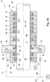
- Fig.2a shows a section view of the sealing device 15 of Fig.1 according to an exemplary embodiment of the invention.
- the sealing device 15 comprises a first axial device end 15a, configured to face toward a cylinder 9 of the compressor 1, which represents a high-pressure side HP.
- the sealing device 15 comprises an opposite second axial device end 15b, configured to face toward a crankcase 2 of the compressor 1 or the distance piece 3 respectively.
- the sealing device 15 comprises a number of first packing retainers 18, each retainer 18 including a retaining opening 18a, in which a first packing ring 19 is arranged.
- Each of the first packing rings is configured for sealing the piston rod 8 during operation of the compressor 1.
- the retaining opening 18a is only indicated for one packing retainer 18 in Fig.2a .
- the first packing retainers 18 can have the shape of a cylindrical disc and can be made of a suitable material such as steel or a steel alloy.
- Each of the first packing rings 19 can for example comprise multiple ring segments in the axial direction (as indicated in Fig.2a ) and/or multiple ring segments in a circumferential direction (not shown).
- a first packing ring 19 can for example comprise a tangentially cut sealing ring and a radially cut sealing ring.
- the tangentially cut sealing ring can comprise a number of ring segments in the circumferential direction, which segments abut at cooperating sealing surfaces in the circumferential direction in order to form a seal in the radial direction.
- the radially cut sealing ring can comprises a number of ring segments in the circumferential direction, the segments being configured to overlap the tangential cuts of the tangentially cut ring, in order to form a seal in the axial direction.
- Also combined rings are known, which have both, tangential cuts and radial cuts.
- a so-called “backup-ring” could be arranged in the retaining opening 18a adjacent a first packing ring 19, which backup-ring can be uncut and which is configured to prevent the ring segments of the first packing ring 19, usually made from plastic from extrusion.
- backup rings are normally made of metal and do not serve for sealing the piston rod. Since those different packing rings are known in the art, no detailed description will be provided at this point.
- the number of first packing rings 19, arranged in the number of first packing retainers 18, do not necessarily need to be identical.
- the sealing device 15 further comprises a second packing retainer 20, which includes a retaining opening 20a, in which a second packing ring 21 is arranged.
- the second packing ring 21 is configured for sealing the piston rod 8 during standstill of the compressor 1, as will be described in further detail below.
- the second packing ring 21 has a different design than the number of first packing rings 19.
- the second packing retainer 20 is positioned closer to the second axial device end 15b than the number of first packing retainers 18, as can be seen in Fig.2a .
- an intermediate plate 27 is arranged in the shown example.
- the intermediate plate 27 delimits the retaining opening 20a of the second packing retainer 20 in the axial direction and also delimits the retaining opening 18a of the subsequent first packing retainer 18 in the axial direction, which openings face each other.
- the intermediate plate 27 therefore separates the second packing ring 21, arranged in the retaining opening 20a of the second packing retainer 20, from the first packing ring 19, which is arranged in the retaining opening 18a of the adjacent first packing retainer 18.
- the arrangement of an intermediate plate 27 is only optional and it could also be omitted, e.g., if the first packing retainers 18 are arranged mirror-inverted.
- the second packing ring 21 is an uncut ring, comprising a continuous inner circumferential sealing surface 21a in the circumferential direction.
- the second packing ring 21 can for example have a U-shaped cross section, wherein an open side of the U-shape faces toward the first axial device end 15a of the sealing device 15.
- the U-shape supports the ring deformation under pressure loading.
- the second packing ring 21 could also be L-shaped.
- a ring with a solid cross section could generally be used as the second packing ring 21. Preferred embodiments of the second packing ring 21 will later be described in connection with Fig.3a-4c .
- the second packing ring 21 is made from a material comprising a polymer, which material has a thermal expansion coefficient ⁇ , which is at least two times higher than the thermal expansion coefficient ⁇ FE of iron.
- the polymer comprises at least one of: polytetrafluoroethylene (known as PTFE), polyphenylene sulphide (known as PPS), polyether ether ketone (known as PEEK), polyimide (known as PI) or polyamide (known as PA).
- PTFE polytetrafluoroethylene
- PPS polyphenylene sulphide
- PEEK polyether ether ketone
- PA polyamide
- PA polyamide
- the second packing ring 21 is further designed, such that at (or below) a defined activation temperature an inner diameter d_i of the second packing ring 21 is smaller than an outer diameter D_a of the piston rod 8, such that the second packing ring 21 is prestressed in a radial direction in order to form a tight seal between the continuous inner circumferential sealing surface 21a of the second packing ring 21 and an outer circumferential surface 8a of the piston rod 8.
- the second packing ring 21 is further designed, such that at a given operating temperature, the inner diameter d_i of the second packing ring 21 is larger than the outer diameter D_a of the piston rod 8, such that the continuous inner circumferential sealing surface 21a is detached from the outer circumferential surface 8a of the piston rod 8 in order to provide a leakage path between the inner circumferential surface 21a of the second packing ring 21 and the outer circumferential surface 8a of the piston rod 8 in the axial direction.
- Fig.2a the cold state at ambient temperature is shown.
- the inner diameter d_i of the second packing ring 21 corresponds to the outer diameter D_a of the piston rod 8.
- the inner diameter d_i of the second packing ring 21 would be smaller than the outer diameter D_a of the piston rod 8, such that an interference, similar to a press fit, exists.
- the activation temperature, at which the second packing ring 21 is in its shrunk state and seals the piston rod 8, is typically 80°C or below.
- the operating temperature, at which the second packing ring 21 is in its extended state and does not seal the piston rod 8, typically lies in the range of 90°C and above.
- the activation temperature highly depends on the operating temperature of the compressor 1, which in turn can vary depending on the particular design and application of the compressor 1. Therefore, once the expected operating temperature is known, the design of the second packing ring 21 can be adapted to a desired activation temperature.
- the operating temperature and activation temperature are preferably temperatures in the region of the piston rod 8, in particular temperatures of the surface 8a of the piston rod 8.
- the temperature of the second packing ring 21 as well as the temperature of the piston rod 8 decrease from the operation temperature to a temperature equal or below the activation temperature, e.g., the ambient temperature or a temperature between the activation temperature and the ambient temperature, such that the second packing ring 21 forms a tight sealing barrier on the surface 8a of the piston rod 8.
- the activation temperature e.g., the ambient temperature or a temperature between the activation temperature and the ambient temperature
- a number of openings 22 are provided on the outer shank 25 of the second packing ring 21, wherein each of the number of openings 22 connects an inside space 23 of the U-shaped packing ring 21 with the radial outer circumferential surface 21b of the second packing ring 21.
- the inside space 23 is formed between the opposite shanks 24, 25 of the U-shape in the radial direction.
- the openings 22 therefore extend through the outer shank 25 and are spaced from opposite axial ends 21c, 21d of the second packing ring 21.
- the number of openings 22 can essentially have any suitable form, e.g., cylindrical drillings or groove-shaped millings. If the second packing ring 21 is for instance 3D-printed, also more complex forms could be used.
- the outer shank 25 of the U-shape has a length b_a in the axial direction which is preferably larger than a length b_i of the inner shank 24 in the axial direction.
- the length b_a of the outer shank 25 is preferably slightly larger than an axial length of the retaining opening 20a of the second packing retainer 20.
- the axial length of the retaining opening 20a of the second packing retainer 20 is formed by a distance between an axial end face of the retaining opening 20a and the opposing axial end face of the intermediate plate 27, as can be seen in Fig.2a .
- Fig.4a shows a U-shaped second packing ring 21, which is essentially similar to the ring shown in Fig.3a-3c . Therefore, only the differences will be described in detail.
- the second packing ring 21 according to Fig.4a additionally comprises an O-ring 37, which has a relatively high elasticity, in particular much higher than the material of the second packing ring 21.
- the O-ring is arranged on a shoulder, which is formed by a circumferential groove 38.
- the circumferential groove 38 is positioned adjacent the outer circumferential surface 21b and adjacent to the surface of the second packing ring 21 at the second axial end 21d.
- Fig.4c shows a cross section of another preferred embodiment of the second packing ring 21.
- the second packing ring 21 comprises a rectangular cross section.
- a number of openings 41 are provided, which in each case connect the first axial end 21c of the second packing ring 21 with the outer circumferential surface 21b of the of the second packing ring 21.
- the openings 41 can essentially have any suitable form, e.g., inclined drillings, as shown in Fig.4c , or intersecting and preferably perpendicular axial and radial openings.
- first support passage end 28a of the support passage 28 does not necessarily need to be connected to the retaining opening 20a. It could as well be located between the second packing ring 21 and the subsequent first packing ring 19, for instance on an inner circumferential surface of the intermediate plate 27. However, if the second packing retainer 20 was designed in another fashion, the first support passage end 28a of the support passage 28 could for instance also be located at an inner circumferential surface of the second packing retainer 20, next to the retaining opening 20a towards the first axial device end 15a. Further a valve 29 for opening and closing the support passage 28 is provided between the first support passage end 28a and the second support passage end 28b.
- the compressor 1 can comprise a suitable operation condition sensor (not shown), which is configured to detect a sensor value, representative for an operation condition of the compressor 1.
- the operation condition sensor can e.g., be a temperature sensor, which is configured to sense the operation temperature.
- the temperature sensor can be arranged at a suitable position in order to sense the operating temperature e.g., in the region of the second packing ring 21 and/or in the region of the piston rod 8.
- the operation condition sensor can be connected to the control unit 17 for submitting the sensor value to the control unit 17.
- the control unit 17 can further be configured to control the valve 29 of the support passage 28 dependent on the sensor value, in particular the operating temperature.
- valve 29 could also be directly controlled by the operation condition sensor, such that no control by the control unit 17 is necessary.
- a thermally actuated valve can be used as the valve 29, which is essentially a combination of the valve 29, the actuator 30 and the operation condition sensor.
- the actuator 30 of the valve 29 can open and close the valve 29 automatically dependent on the detected sensor value, without a control intervention of the control unit 17 being required.
- FIG.2a further packing retainers could additionally be arranged in the sealing device 15.
- a fourth packing retainer 42 adjacent the third packing retainer 32 the fourth packing retainer 42 being closer to the second axial device end 15b, than the third packing retainer 32.
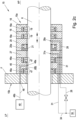
- An exemplary embodiment is shown in Fig.2b .
- the fourth packing retainer 42 includes a retaining opening 42a, in which a wiper ring 43 is arranged, which wiper ring 43 serves for wiping residual oil from the outer circumferential surface 8a of the piston rod 8.
- a wiper ring 43 can comprise one or more wiping edges 43a on the inner circumferential surface.
- the first vent passage end 31a in this case is located on the inner circumferential surface of the second packing retainer 20.
- the second packing retainer 20 also serves as a mounting flange for mounting the sealing device 15 on the compressor 1.
- suitable mounting means such as bolts or screws, can be provided on the flange.
- the function of the vent passage 31 is however the same, as in Fig.2a .
- Such a design is advantageous, because a standardized packing retainer (without an integrated passage) can be used the third packing retainer 32.
- the first packing ring 19_1 which is adjacent the second packing ring 21, is designed differently than the subsequent first packing ring 19_2 (and differently than the further first packing rings 19_3, which are arranged adjacent the first packing ring 19_2 towards the first axial device end 15a in Fig.2b ).
- the first packing ring 19_1 is preferably designed as a so-called "double-acting" ring, which is configured to provide a sealing effect also in absence of a differential pressure over the ring.
- a double-acting ring can for example comprise a ring assembly with two tangentially cut rings, e.g., two identical tangentially cut rings.
- the second packing ring 21 could have a different design, as was described in connection with Flg.3a- Fig.4c .
- the first vent passage end 31a of the vent passage 31 is located between the second packing ring 21 and the subsequent first packing ring 19 in the direction of the second device end 15b, similar as in the embodiment according to Fig.2b .
- the sealing device 15 further comprises a fifth packing retainer 46 having a T-like cross section and comprising two retaining openings 46a, which are separated by a central part of the T-like cross section in the axial direction.
- a fifth packing ring 47 is arranged in each of the retaining openings 46a.
- the fifth packing rings 47 are each formed as a so-called single-acting SLP-ring assembly, which comprises three consecutive rings in the axial direction, wherein each of the three rings being a cut ring, comprising multiple ring segments in the circumferential direction.
- the central ring and one of the outer rings each comprise a chamfer, wherein the chamfer of the central ring faces towards the outside in the radial direction and the chamfer on the outer ring faces towards the inside in the radial direction.
- the chamfers face each other and are in contact.
Landscapes
- Engineering & Computer Science (AREA)
- General Engineering & Computer Science (AREA)
- Mechanical Engineering (AREA)
- Physics & Mathematics (AREA)
- Architecture (AREA)
- Fluid Mechanics (AREA)
- Compressor (AREA)
- Details Of Reciprocating Pumps (AREA)
- Sealing Devices (AREA)
Claims (15)
- Dichtungsvorrichtung (15) zum Abdichten einer Kolbenstange (8) eines Kolbenkompressors (1), wobei die Dichtungsvorrichtung (15) umfasst: ein erstes axiales Vorrichtungsende (15a), das konfiguriert ist, um einem Zylinder (9) des Kompressors (1) zugewandt zu sein, und ein gegenüberliegendes zweites axiales Vorrichtungsende (15b), das konfiguriert ist, um einem Kurbelgehäuse (2) des Kompressors (1) zugewandt zu sein, eine Anzahl von ersten Packungshaltern (18), wobei jeder Halter eine Halteöffnung (18a) aufweist, in der ein erster Packungsring (19) angeordnet ist, einen zweiten Packungshalter (20), der eine Halteöffnung (20a) aufweist, in der ein zweiter Packungsring (21) angeordnet ist, wobei der zweite Halter (20) näher dem zweiten axialen Dichtungsende (15b) angeordnet ist als die Anzahl von ersten Packungshaltern (18) in einer axialen Richtung der Dichtungsvorrichtung (15), wobei der zweite Packungsring (21) ein ungeschnittener Ring (21) ist, der eine durchgehende innere Umfangsdichtungsfläche (21a) umfasst, wobei der zweite Packungsring aus einem Material hergestellt ist, das ein Polymer umfasst, dadurch gekennzeichnet, dass das Material einen Wärmeausdehnungskoeffizienten (α) aufweist, der mindestens doppelt so hoch ist wie der Wärmeausdehnungskoeffizient (αFE) von Eisen, wobei bei oder unterhalb einer definierten Aktivierungstemperatur ein Innendurchmesser (d_i) des zweiten Packungsrings (21) kleiner ist als ein Außendurchmesser (D_a) der abzudichtenden Kolbenstange (8), sodass im montierten Zustand der Dichtungsvorrichtung (15) im Kompressor (1) der zweite Packungsring (21) in radialer Richtung vorgespannt ist, um eine dichte Abdichtung zwischen der durchgehenden inneren Umfangsdichtungsfläche (21a) des zweiten Packungsrings (21) und der Außenumfangsfläche (8a) der Kolbenstange (8) zu bilden, wobei bei einer gegebenen Betriebstemperatur der Innendurchmesser (d_i) des zweiten Packungsrings (21) größer ist als der Außendurchmesser (D_a) der Kolbenstange (8), sodass im montierten Zustand der Dichtungsvorrichtung (15) im Kompressor (1) die durchgehende innere Umfangsdichtungsfläche (21a) des zweiten Abdichtungsrings (21) von der Außenumfangsfläche (8a) der Kolbenstange (8) gelöst ist, um einen Leckagepfad am zweiten Packungsring (21) in axialer Richtung vorbei bereitzustellen.
- Dichtungsvorrichtung (15) nach Anspruch 1, wobei der Wärmeausdehnungskoeffizient (α) des Materials des zweiten Packungsrings (21) mindestens 30×10-6 K-1 beträgt, vorzugsweise mindestens 60×10-6 K-1, insbesondere mindestens 90×10-6K-1.
- Dichtungsvorrichtung (15) nach Anspruch 1 oder 2, wobei die Betriebstemperatur 90°C oder mehr beträgt und/oder wobei die Aktivierungstemperatur 80°C oder weniger beträgt, wobei es sich bei der Betriebstemperatur und der Aktivierungstemperatur um Temperaturen im Bereich der Kolbenstange (8) handelt, insbesondere um eine Temperatur der Außenumfangsfläche (8a) der Kolbenstange (8).
- Dichtungsvorrichtung (15) nach einem der Ansprüche 1 bis 3, wobei der zweite Packungsring (21) ein erstes axiales Ende (21c) und ein gegenüberliegendes zweites axiales Ende (21d) aufweist, wobei der zweite Packungsring (21) in der Halteöffnung (20a) des zweiten Packungshalters (20) angeordnet ist, sodass das erste axiale Ende (21c) dem ersten axialen Vorrichtungsende (15a) der Dichtungsvorrichtung (15) zugewandt ist und wobei der zweite Packungsring (21) eines von Folgenden umfasst:- einen U-förmigen Querschnitt, umfassend einen inneren Schaft (24) und einen äußeren Schaft (25), die in radialer Richtung voneinander beabstandet sind, wobei die innere Umfangsdichtungsfläche (21a) des zweiten Packungsrings (21) an dem inneren Schaft (24) bereitgestellt ist und eine radial äußere Umfangsfläche (21b) an dem äußeren Schaft (25) des zweiten Packungsrings (21) bereitgestellt ist, wobei eine offene Seite der U-Form in axialer Richtung dem ersten axialen Ende (21c) des zweiten Packungsrings (21) zugewandt ist,- einen L-förmigen Querschnitt, umfassend einen axialen Schaft (39) und einen radialen Schaft (40) umfasst, wobei die innere Umlaufdichtungsfläche (21a) des zweiten Packungsrings (21) an dem axialen Schaft (39) bereitgestellt ist und eine radial äußere Umfangsfläche (21b) des zweiten Packungsrings (21) an dem radialen Schaft (40) bereitgestellt ist, wobei der radiale Schaft (40) am zweiten axialen Ende (21d) des zweiten Packungsrings (21) angeordnet ist,- einen rechteckigen Querschnitt, wobei am zweiten Packungsring (21) eine Anzahl an Öffnungen (41) bereitgestellt ist, wobei die Öffnungen (41) jeweils das erste axiale Ende (21c) des zweiten Packungsrings (21) mit einer Außenumfangsfläche (21b) des zweiten Packungsrings (21) verbinden.
- Dichtungsvorrichtung (15) nach Anspruch 4, wobei am Außenschaft (25) eine Anzahl an Öffnungen (22) bereitgestellt ist, wobei jede der Anzahl an Öffnungen (22) einen Innenraum (23) des U-förmigen Packungsrings (21) mit der radial Außenumfangsfläche (21b) des zweiten Packungsrings (21) verbindet, wobei der Innenraum (23) in radialer Richtung zwischen dem Innenschaft (24) und dem Außenschaft (25) liegt, wobei die Öffnungen (22) von den gegenüberliegenden axialen Enden (21c, 21d) des zweiten Packungsrings (21) beabstandet sind.
- Dichtungsvorrichtung (15) nach Anspruch 5, wobei die Anzahl an Öffnungen (22) eine Anzahl von länglichen Löchern oder elliptischen Löchern umfasst.
- Dichtungsvorrichtung (15) nach Anspruch 6, wobei jedes längliche Loch oder elliptische Loch eine Längsachse (L), ein erstes Lochende (22a) und ein in Richtung der Längsachse (L) gegenüberliegendes zweites Lochende (22b) umfasst, wobei das erste Lochende (22a) näher am ersten Ringende (21c) liegt als das zweite Lochende (22b).
- Dichtungsvorrichtung (15) nach einem der Ansprüche 4 bis 7, wobei im unmontierten Zustand des zweiten Packungsrings (21) eine Länge (b_i) des Innenschafts (24) in axialer Richtung kleiner ist als eine Länge (b_a) des Außenschafts (25) in axialer Richtung.
- Dichtungsvorrichtung (15) nach einem der Ansprüche 1 bis 8, wobei das Material des zweiten Packungsrings (21) ein faserverstärkter Verbundwerkstoff ist und/oder dass das Polymer des Materials des zweiten Packungsrings (21) mindestens eines umfasst von: Polytetrafluorethylen, Polyphenylensulfid, Polyetheretherketon, Polyimid, Polyamid.
- Dichtungsvorrichtung (15) nach einem der Ansprüche 1 bis 9, wobei die Dichtungsvorrichtung (15) ferner einen ungehinderten Entlüftungsdurchgang (31) mit einem ersten Entlüftungsdurchgangsende (31a) und einem zweiten Entlüftungsdurchgangsende (31b) umfasst, wobei der Entlüftungsdurchgang (31) konfiguriert ist, um ein Gas, das von dem ersten axialen Vorrichtungsende (15a) in Richtung des zweiten axialen Vorrichtungsendes (15b) an dem zweiten Packungsring (21) vorbei leckt, vom ersten Entlüftungsdurchgangsende (31a) zum zweiten Entlüftungsdurchgangsende (31b) zu entlüften.
- Dichtungsvorrichtung (15) nach einem der Ansprüche 1 bis 10, wobei die Dichtungsvorrichtung (15) ferner mindestens einen dritten Packungshalter (32) mit einer Halteöffnung (32a) umfasst, in der ein dritter Packungsring (33) angeordnet ist, wobei der mindestens eine dritte Packungshalter (32) näher am zweiten axialen Vorrichtungsende (15b) der Dichtungsvorrichtung (15) angeordnet ist als der zweite Packungshalter (20).
- Dichtungsvorrichtung (15) nach Anspruch 11 mit einem ungehinderten Entlüftungsdurchgang nach Anspruch 10, wobei das erste Entlüftungsdurchgangsende (31a) mit der Halteöffnung (32a) des dritten Packungshalters (32) verbunden ist, vorzugsweise radial außerhalb des mindestens einen dritten Packungsrings (33), oder wobei sich das erste Entlüftungsdurchgangsende (31a) in axialer Richtung der Dichtungsvorrichtung (15) zwischen dem zweiten Packungsring (21) und dem dritten Packungsring (33) befindet.
- Hubkolbenkompressor (1), umfassend eine Anzahl von Zylindern (9), wobei in jedem der Zylinder (9) ein hin- und herbewegbarer Kolben (10) angeordnet ist, wobei jeder Kolben (10) mit einer Kolbenstange (8) verbunden ist, wobei für mindestens einen Zylinder (9) der Anzahl von Zylindern (9) eine Dichtungsvorrichtung (15) nach einem der Ansprüche 1 bis 12 zum Abdichten der jeweiligen Kolbenstange (8) bereitgestellt ist, wobei die Dichtungsvorrichtung (15) so angeordnet ist, dass das erste axiale Vorrichtungsende (15a) dem Zylinder (9) zugewandt ist und das zweite axiale Vorrichtungsende (15b) einem Kurbelgehäuse (2) des Kompressors (1) zugewandt ist.
- Verfahren zum Betreiben eines Hubkolbenkompressors (1), wobei der Kompressor (1) eine Anzahl von Zylindern (9) umfasst, wobei in jedem der Zylinder (9) ein Kolben (10) angeordnet ist, der hin und her bewegbar ist, wobei jeder Kolben (10) mit einer Kolbenstange (8) verbunden ist, wobei für jeden Zylinder (9) der Anzahl von Zylindern (9) eine Dichtungsvorrichtung (15) zum Abdichten der jeweiligen Kolbenstange (8) bereitgestellt ist, wobei die Vorrichtung ein erstes axiales Vorrichtungsende (15a), das dem jeweiligen Zylinder (9) zugewandt ist, und ein gegenüberliegendes zweites axialesVorrichtungsende (15b), das einem Kurbelgehäuse (2) des Kompressors (1) zugewandt ist, umfasst, wobei mindestens eine Dichtungsvorrichtung (15) der Anzahl von Dichtungsvorrichtungen eine Anzahl von ersten Packungshaltern (18) umfasst, wobei jeder Halter eine Halteöffnung (18a) aufweist, in der ein erster Packungsring (19) angeordnet ist, einen zweiten Packungshalter (20), der eine Halteöffnung (20a) aufweist, in der ein zweiter Packungsring (21) angeordnet ist, wobei der zweite Halter (20a) näher am zweiten axialen Vorrichtungsende (15b) positioniert ist als die Anzahl der ersten Packungshalter (18) in einer axialen Richtung der Dichtungsvorrichtung (15), wobei der zweite Packungsring (21) ein ungeschnittener Ring ist, der eine durchgehende innere Umfangsdichtungsfläche (21a) umfasst, wobei der zweite Packungsring (21) aus einem Material hergestellt ist, das ein Polymer umfasst,dadurch gekennzeichnet, dass das Material einen Wärmeausdehnungskoeffizienten (α) aufweist, der mindestens doppelt so hoch ist wie der Wärmeausdehnungskoeffizient (α FE) von Eisen, wobei das Verfahren umfasst:- Starten eines Betriebs des Kompressors (1) aus dem Stillstand bei oder unterhalb einer Aktivierungstemperatur, wobei bei oder unterhalb der Aktivierungstemperatur der zweite Packungsring (21) in radialer Richtung vorgespannt wird, um eine dichte Abdichtung zwischen der durchgehenden inneren Umfangsdichtungsfläche (21a) des zweiten Packungsrings (21) und der Außenumfangsfläche (8a) der Kolbenstange (8) zu bilden,- Betreiben des Kompressors (1) bis zum Erreichen einer vordefinierten Betriebstemperatur, wobei sich beim Erreichen der Betriebstemperatur die durchgehende innere Umfangsdichtungsfläche (21a) des zweiten Packungsrings (21) von der Außenumfangsfläche (8a) der Kolbenstange (8) löst und einen Leckagepfad zwischen der inneren Umfangsdichtungsfläche (21a) des zweiten Packungsrings (21) und der Außenumfangsfläche (8a) der Kolbenstange (8) in axialer Richtung bereitstellt.
- Verfahren nach Anspruch 14, wobei das Verfahren ferner umfasst:- Stoppen des Betriebs des Kompressors (1) bis zum Stillstand,- Abkühlen des Kompressors (1) bis zu oder unterhalb der Aktivierungstemperatur, wobei sich beim Erreichen der Aktivierungstemperatur die durchgehende innere Umfangsdichtungsfläche (21a) des zweiten Packungsrings (21) an die äußere Umfangsfläche (8a) der Kolbenstange (8) anlegt und eine dichte Abdichtung zwischen der durchgehenden inneren Umfangsdichtungsfläche (21a) des zweiten Packungsrings (21) und der Außenumfangsfläche der Kolbenstange (8) bildet.
Applications Claiming Priority (2)
| Application Number | Priority Date | Filing Date | Title |
|---|---|---|---|
| US17/988,364 US12326140B2 (en) | 2022-11-16 | 2022-11-16 | Sealing device for a piston rod of a reciprocating compressor |
| PCT/EP2023/081701 WO2024105006A1 (en) | 2022-11-16 | 2023-11-14 | Sealing device for a piston rod of a reciprocating compressor |
Publications (3)
| Publication Number | Publication Date |
|---|---|
| EP4409138A1 EP4409138A1 (de) | 2024-08-07 |
| EP4409138C0 EP4409138C0 (de) | 2025-01-29 |
| EP4409138B1 true EP4409138B1 (de) | 2025-01-29 |
Family
ID=88839432
Family Applications (1)
| Application Number | Title | Priority Date | Filing Date |
|---|---|---|---|
| EP23808717.5A Active EP4409138B1 (de) | 2022-11-16 | 2023-11-14 | Dichtungsvorrichtung für eine kolbenstange eines hubkolbenverdichters |
Country Status (6)
| Country | Link |
|---|---|
| US (1) | US12326140B2 (de) |
| EP (1) | EP4409138B1 (de) |
| JP (1) | JP7770584B2 (de) |
| CN (1) | CN118613655A (de) |
| CA (1) | CA3249259A1 (de) |
| WO (1) | WO2024105006A1 (de) |
Families Citing this family (2)
| Publication number | Priority date | Publication date | Assignee | Title |
|---|---|---|---|---|
| IT201800010391A1 (it) * | 2018-11-16 | 2020-05-16 | Nuovo Pignone Tecnologie Srl | Premistoppa per utilizzo con aste di pistoni mobili reciprocamente e relativo metodo di costruzione |
| US12331836B2 (en) * | 2019-04-18 | 2025-06-17 | A. W. Chesterton Company | System and method for automatically energizing packing material with a packing loading assembly |
Citations (10)
| Publication number | Priority date | Publication date | Assignee | Title |
|---|---|---|---|---|
| US5163692A (en) | 1989-07-24 | 1992-11-17 | Furon Company | One-piece composite lip seal |
| WO2002016809A2 (en) | 2000-08-21 | 2002-02-28 | Westport Research Inc. | Seal assembly with two sealing mechanisms for providing static and dynamic sealing |
| US20120211945A1 (en) | 2011-02-17 | 2012-08-23 | Hoerbiger Kompressortechnik Holding Gmbh | Sealing packing for a reciprocating piston rod of a reciprocating compressor |
| WO2017140297A2 (de) | 2016-02-16 | 2017-08-24 | Devetec Gmbh | Wärmekraftmaschine, insbesondere orc-motor |
| WO2018037135A1 (de) | 2016-08-26 | 2018-03-01 | Burckhardt Compression Ag | Ölabstreifpackung |
| US20180112778A1 (en) | 2016-10-24 | 2018-04-26 | Bal Seal Engineering, Inc. | Seal assemblies for extreme temperatures and related methods |
| EP3330538A1 (de) | 2016-12-05 | 2018-06-06 | Compressor Products International, LLC | Aufblasbare statische dichtung für eine kolbenstange einer hubkolbenpumpe oder eines hubkolbenverdichters |
| US20200088298A1 (en) | 2018-03-20 | 2020-03-19 | Mitsui E&S Machinery Co., Ltd. | Rod packing |
| US10883483B2 (en) | 2018-09-28 | 2021-01-05 | Air Products And Chemicals, Inc. | Seal assembly for reciprocating compressor |
| US20220136494A1 (en) | 2019-01-29 | 2022-05-05 | Hoerbiger Wien Gmbh | Packaging ring with relief opening |
Family Cites Families (14)
| Publication number | Priority date | Publication date | Assignee | Title |
|---|---|---|---|---|
| US3216651A (en) * | 1963-07-01 | 1965-11-09 | Battelle Development Corp | Seal |
| US3403917A (en) * | 1965-11-19 | 1968-10-01 | Robbins Aviat Inc | Dynamic shaft sealing device |
| US4194745A (en) * | 1979-05-02 | 1980-03-25 | Mcdougal Thomas L | Controlled clearance seal |
| US4469017A (en) | 1983-02-23 | 1984-09-04 | Dover Corporation | Static leak seal assembly for use in fluid containing machinery |
| US4553759A (en) * | 1984-12-10 | 1985-11-19 | Cameron Iron Works, Inc. | Valve and improved stem seal therefor |
| JPH06241262A (ja) * | 1993-02-19 | 1994-08-30 | Tokico Ltd | 密閉型シリンダ装置 |
| JP3742164B2 (ja) * | 1996-11-19 | 2006-02-01 | 株式会社日立製作所 | 往復動圧縮機 |
| US5984316A (en) * | 1997-12-12 | 1999-11-16 | Bal Seal Engineering Company, Inc. | Rotary reciprocating seals with internal metal band |
| US6932351B1 (en) * | 2003-02-07 | 2005-08-23 | William L. Mowll | Packing case for cooling compressors and other machinery |
| JP2011032938A (ja) | 2009-07-31 | 2011-02-17 | Starlite Co Ltd | 温度補償型シール装置 |
| JP2014224544A (ja) | 2014-09-08 | 2014-12-04 | 株式会社 ユニフローズ | 送液用ポンプ装置 |
| US10626994B2 (en) * | 2015-07-24 | 2020-04-21 | Saint-Gobain Performance Plastics Corporation | Scraper ring |
| CN112203912B (zh) | 2018-05-29 | 2023-04-14 | 日立安斯泰莫株式会社 | 主缸 |
| CN110375067B (zh) * | 2019-06-25 | 2024-06-14 | 北京北分瑞利分析仪器(集团)有限责任公司 | 一种应用于注射器的活塞密封结构 |
-
2022
- 2022-11-16 US US17/988,364 patent/US12326140B2/en active Active
-
2023
- 2023-11-14 EP EP23808717.5A patent/EP4409138B1/de active Active
- 2023-11-14 CA CA3249259A patent/CA3249259A1/en active Pending
- 2023-11-14 JP JP2024546049A patent/JP7770584B2/ja active Active
- 2023-11-14 CN CN202380018670.3A patent/CN118613655A/zh active Pending
- 2023-11-14 WO PCT/EP2023/081701 patent/WO2024105006A1/en not_active Ceased
Patent Citations (10)
| Publication number | Priority date | Publication date | Assignee | Title |
|---|---|---|---|---|
| US5163692A (en) | 1989-07-24 | 1992-11-17 | Furon Company | One-piece composite lip seal |
| WO2002016809A2 (en) | 2000-08-21 | 2002-02-28 | Westport Research Inc. | Seal assembly with two sealing mechanisms for providing static and dynamic sealing |
| US20120211945A1 (en) | 2011-02-17 | 2012-08-23 | Hoerbiger Kompressortechnik Holding Gmbh | Sealing packing for a reciprocating piston rod of a reciprocating compressor |
| WO2017140297A2 (de) | 2016-02-16 | 2017-08-24 | Devetec Gmbh | Wärmekraftmaschine, insbesondere orc-motor |
| WO2018037135A1 (de) | 2016-08-26 | 2018-03-01 | Burckhardt Compression Ag | Ölabstreifpackung |
| US20180112778A1 (en) | 2016-10-24 | 2018-04-26 | Bal Seal Engineering, Inc. | Seal assemblies for extreme temperatures and related methods |
| EP3330538A1 (de) | 2016-12-05 | 2018-06-06 | Compressor Products International, LLC | Aufblasbare statische dichtung für eine kolbenstange einer hubkolbenpumpe oder eines hubkolbenverdichters |
| US20200088298A1 (en) | 2018-03-20 | 2020-03-19 | Mitsui E&S Machinery Co., Ltd. | Rod packing |
| US10883483B2 (en) | 2018-09-28 | 2021-01-05 | Air Products And Chemicals, Inc. | Seal assembly for reciprocating compressor |
| US20220136494A1 (en) | 2019-01-29 | 2022-05-05 | Hoerbiger Wien Gmbh | Packaging ring with relief opening |
Non-Patent Citations (5)
| Title |
|---|
| ANONYMOUS: "O-ring", WIKIPEDIA, 23 October 2025 (2025-10-23), XP093332280, Retrieved from the Internet <URL:https://en.wikipedia.org/w/index.php?title=O-ring&oldid=1318284171> |
| ANONYMOUS: "PTFE: Polytetrafluoroethylene ", NETZSCH POLYMERS, 1 January 2025 (2025-01-01), XP093332273, Retrieved from the Internet <URL: https://polymers.netzsch.com/Materials/Details/34> |
| ANONYMOUS: "Reciprocating compressor ", WIKIPEDIA, 17 August 2025 (2025-08-17), XP093332279, Retrieved from the Internet <URL:https://en.wikipedia.org/w/index.php?title=Reciprocating compressor&oldid=1306397863> |
| ANONYMOUS: "SBR: Styrene-butadiene rubber", NETZSCH (ACCESSED VIA THE WAYBACK MACHINE), 13 September 2024 (2024-09-13), XP093332275, Retrieved from the Internet <URL:https://web.archive.org/web/20240913010752/https://analyzing-testing.netzsch.com/en/polymers-netzsch-com/elastomers/sbr-styrene-butadiene-rubber> |
| ANONYMOUS: "Thermal expansion", WIKIPEDIA, 4 October 2025 (2025-10-04), XP093332271, Retrieved from the Internet <URL:https://en.wikipedia.org/w/index.php?title=Thermal expansion&oldid=1314965383> |
Also Published As
| Publication number | Publication date |
|---|---|
| JP2025505593A (ja) | 2025-02-28 |
| WO2024105006A1 (en) | 2024-05-23 |
| US20240159229A1 (en) | 2024-05-16 |
| US12326140B2 (en) | 2025-06-10 |
| EP4409138C0 (de) | 2025-01-29 |
| CN118613655A (zh) | 2024-09-06 |
| JP7770584B2 (ja) | 2025-11-14 |
| CA3249259A1 (en) | 2024-05-23 |
| EP4409138A1 (de) | 2024-08-07 |
Similar Documents
| Publication | Publication Date | Title |
|---|---|---|
| EP4409138B1 (de) | Dichtungsvorrichtung für eine kolbenstange eines hubkolbenverdichters | |
| EP2591211B1 (de) | Fluiddichtungsvorrichtung für drehmaschinen | |
| US8408556B2 (en) | Low and reverse pressure application hydrodynamic pressurizing seals | |
| JP7308840B2 (ja) | 流体シール装置を備えるターボマシン | |
| JP2009103012A (ja) | スクリュ流体機械 | |
| EP1738095A2 (de) | Dichtung mit geringem leckagegrad für druckantrieb mit hoher ablenkung über der mitte | |
| WO1995020731A1 (en) | Backup seal for sealing between a shaft and housing | |
| US7654791B2 (en) | Apparatus and method for controlling a blade tip clearance for a compressor | |
| EP4409137B1 (de) | Dichtungsvorrichtung für eine kolbenstange eines hubkolbenverdichters | |
| US4071254A (en) | Static sealing mechanism for a compressor | |
| US6905123B2 (en) | Seals |
Legal Events
| Date | Code | Title | Description |
|---|---|---|---|
| STAA | Information on the status of an ep patent application or granted ep patent |
Free format text: STATUS: UNKNOWN |
|
| STAA | Information on the status of an ep patent application or granted ep patent |
Free format text: STATUS: THE INTERNATIONAL PUBLICATION HAS BEEN MADE |
|
| PUAI | Public reference made under article 153(3) epc to a published international application that has entered the european phase |
Free format text: ORIGINAL CODE: 0009012 |
|
| STAA | Information on the status of an ep patent application or granted ep patent |
Free format text: STATUS: REQUEST FOR EXAMINATION WAS MADE |
|
| 17P | Request for examination filed |
Effective date: 20240430 |
|
| AK | Designated contracting states |
Kind code of ref document: A1 Designated state(s): AL AT BE BG CH CY CZ DE DK EE ES FI FR GB GR HR HU IE IS IT LI LT LU LV MC ME MK MT NL NO PL PT RO RS SE SI SK SM TR |
|
| REG | Reference to a national code |
Ref country code: DE Ref legal event code: R079 Free format text: PREVIOUS MAIN CLASS: F04B0039000000 Ipc: F04B0005020000 Ref country code: DE Ref legal event code: R079 Ref document number: 602023001936 Country of ref document: DE Free format text: PREVIOUS MAIN CLASS: F04B0039000000 Ipc: F04B0005020000 |
|
| GRAP | Despatch of communication of intention to grant a patent |
Free format text: ORIGINAL CODE: EPIDOSNIGR1 |
|
| STAA | Information on the status of an ep patent application or granted ep patent |
Free format text: STATUS: GRANT OF PATENT IS INTENDED |
|
| RIC1 | Information provided on ipc code assigned before grant |
Ipc: F16J 15/46 20060101ALI20240827BHEP Ipc: F16J 15/3236 20160101ALI20240827BHEP Ipc: F16J 15/26 20060101ALI20240827BHEP Ipc: F16J 15/00 20060101ALI20240827BHEP Ipc: F04B 53/14 20060101ALI20240827BHEP Ipc: F04B 39/04 20060101ALI20240827BHEP Ipc: F04B 39/00 20060101ALI20240827BHEP Ipc: F04B 5/02 20060101AFI20240827BHEP |
|
| DAV | Request for validation of the european patent (deleted) | ||
| DAX | Request for extension of the european patent (deleted) | ||
| INTG | Intention to grant announced |
Effective date: 20240920 |
|
| GRAS | Grant fee paid |
Free format text: ORIGINAL CODE: EPIDOSNIGR3 |
|
| GRAA | (expected) grant |
Free format text: ORIGINAL CODE: 0009210 |
|
| STAA | Information on the status of an ep patent application or granted ep patent |
Free format text: STATUS: THE PATENT HAS BEEN GRANTED |
|
| AK | Designated contracting states |
Kind code of ref document: B1 Designated state(s): AL AT BE BG CH CY CZ DE DK EE ES FI FR GB GR HR HU IE IS IT LI LT LU LV MC ME MK MT NL NO PL PT RO RS SE SI SK SM TR |
|
| REG | Reference to a national code |
Ref country code: GB Ref legal event code: FG4D |
|
| REG | Reference to a national code |
Ref country code: CH Ref legal event code: EP |
|
| REG | Reference to a national code |
Ref country code: DE Ref legal event code: R096 Ref document number: 602023001936 Country of ref document: DE |
|
| REG | Reference to a national code |
Ref country code: IE Ref legal event code: FG4D |
|
| U01 | Request for unitary effect filed |
Effective date: 20250212 |
|
| U07 | Unitary effect registered |
Designated state(s): AT BE BG DE DK EE FI FR IT LT LU LV MT NL PT RO SE SI Effective date: 20250218 |
|
| PG25 | Lapsed in a contracting state [announced via postgrant information from national office to epo] |
Ref country code: RS Free format text: LAPSE BECAUSE OF FAILURE TO SUBMIT A TRANSLATION OF THE DESCRIPTION OR TO PAY THE FEE WITHIN THE PRESCRIBED TIME-LIMIT Effective date: 20250429 |
|
| PG25 | Lapsed in a contracting state [announced via postgrant information from national office to epo] |
Ref country code: PL Free format text: LAPSE BECAUSE OF FAILURE TO SUBMIT A TRANSLATION OF THE DESCRIPTION OR TO PAY THE FEE WITHIN THE PRESCRIBED TIME-LIMIT Effective date: 20250129 |
|
| PG25 | Lapsed in a contracting state [announced via postgrant information from national office to epo] |
Ref country code: ES Free format text: LAPSE BECAUSE OF FAILURE TO SUBMIT A TRANSLATION OF THE DESCRIPTION OR TO PAY THE FEE WITHIN THE PRESCRIBED TIME-LIMIT Effective date: 20250129 |
|
| PG25 | Lapsed in a contracting state [announced via postgrant information from national office to epo] |
Ref country code: IS Free format text: LAPSE BECAUSE OF FAILURE TO SUBMIT A TRANSLATION OF THE DESCRIPTION OR TO PAY THE FEE WITHIN THE PRESCRIBED TIME-LIMIT Effective date: 20250529 Ref country code: NO Free format text: LAPSE BECAUSE OF FAILURE TO SUBMIT A TRANSLATION OF THE DESCRIPTION OR TO PAY THE FEE WITHIN THE PRESCRIBED TIME-LIMIT Effective date: 20250429 |
|
| PG25 | Lapsed in a contracting state [announced via postgrant information from national office to epo] |
Ref country code: HR Free format text: LAPSE BECAUSE OF FAILURE TO SUBMIT A TRANSLATION OF THE DESCRIPTION OR TO PAY THE FEE WITHIN THE PRESCRIBED TIME-LIMIT Effective date: 20250129 |
|
| PG25 | Lapsed in a contracting state [announced via postgrant information from national office to epo] |
Ref country code: GR Free format text: LAPSE BECAUSE OF FAILURE TO SUBMIT A TRANSLATION OF THE DESCRIPTION OR TO PAY THE FEE WITHIN THE PRESCRIBED TIME-LIMIT Effective date: 20250430 |
|
| PG25 | Lapsed in a contracting state [announced via postgrant information from national office to epo] |
Ref country code: SM Free format text: LAPSE BECAUSE OF FAILURE TO SUBMIT A TRANSLATION OF THE DESCRIPTION OR TO PAY THE FEE WITHIN THE PRESCRIBED TIME-LIMIT Effective date: 20250129 |
|
| PG25 | Lapsed in a contracting state [announced via postgrant information from national office to epo] |
Ref country code: CZ Free format text: LAPSE BECAUSE OF FAILURE TO SUBMIT A TRANSLATION OF THE DESCRIPTION OR TO PAY THE FEE WITHIN THE PRESCRIBED TIME-LIMIT Effective date: 20250129 |
|
| PG25 | Lapsed in a contracting state [announced via postgrant information from national office to epo] |
Ref country code: SK Free format text: LAPSE BECAUSE OF FAILURE TO SUBMIT A TRANSLATION OF THE DESCRIPTION OR TO PAY THE FEE WITHIN THE PRESCRIBED TIME-LIMIT Effective date: 20250129 |
|
| PLBI | Opposition filed |
Free format text: ORIGINAL CODE: 0009260 |
|
| PLAX | Notice of opposition and request to file observation + time limit sent |
Free format text: ORIGINAL CODE: EPIDOSNOBS2 |
|
| 26 | Opposition filed |
Opponent name: BURCKHARDT COMPRESSION AG Effective date: 20251029 |
|
| U20 | Renewal fee for the european patent with unitary effect paid |
Year of fee payment: 3 Effective date: 20251201 |