EP4408020A1 - Vibrationssensor und mikrofon - Google Patents
Vibrationssensor und mikrofon Download PDFInfo
- Publication number
- EP4408020A1 EP4408020A1 EP22942109.4A EP22942109A EP4408020A1 EP 4408020 A1 EP4408020 A1 EP 4408020A1 EP 22942109 A EP22942109 A EP 22942109A EP 4408020 A1 EP4408020 A1 EP 4408020A1
- Authority
- EP
- European Patent Office
- Prior art keywords
- vibration
- cavity
- piezoelectric
- vibration sensor
- dimension
- Prior art date
- Legal status (The legal status is an assumption and is not a legal conclusion. Google has not performed a legal analysis and makes no representation as to the accuracy of the status listed.)
- Pending
Links
Images


Classifications
-
- H—ELECTRICITY
- H10—SEMICONDUCTOR DEVICES; ELECTRIC SOLID-STATE DEVICES NOT OTHERWISE PROVIDED FOR
- H10N—ELECTRIC SOLID-STATE DEVICES NOT OTHERWISE PROVIDED FOR
- H10N30/00—Piezoelectric or electrostrictive devices
- H10N30/30—Piezoelectric or electrostrictive devices with mechanical input and electrical output, e.g. functioning as generators or sensors
- H10N30/302—Sensors
-
- H—ELECTRICITY
- H04—ELECTRIC COMMUNICATION TECHNIQUE
- H04R—LOUDSPEAKERS, MICROPHONES, GRAMOPHONE PICK-UPS OR LIKE ACOUSTIC ELECTROMECHANICAL TRANSDUCERS; ELECTRIC HEARING AIDS; PUBLIC ADDRESS SYSTEMS
- H04R17/00—Piezoelectric transducers; Electrostrictive transducers
- H04R17/10—Resonant transducers, i.e. adapted to produce maximum output at a predetermined frequency
-
- B—PERFORMING OPERATIONS; TRANSPORTING
- B81—MICROSTRUCTURAL TECHNOLOGY
- B81B—MICROSTRUCTURAL DEVICES OR SYSTEMS, e.g. MICROMECHANICAL DEVICES
- B81B7/00—Microstructural systems ; Auxiliary parts of microstructural devices or systems
- B81B7/04—Networks or arrays of similar microstructural devices
-
- H—ELECTRICITY
- H04—ELECTRIC COMMUNICATION TECHNIQUE
- H04R—LOUDSPEAKERS, MICROPHONES, GRAMOPHONE PICK-UPS OR LIKE ACOUSTIC ELECTROMECHANICAL TRANSDUCERS; ELECTRIC HEARING AIDS; PUBLIC ADDRESS SYSTEMS
- H04R17/00—Piezoelectric transducers; Electrostrictive transducers
- H04R17/02—Microphones
-
- H—ELECTRICITY
- H10—SEMICONDUCTOR DEVICES; ELECTRIC SOLID-STATE DEVICES NOT OTHERWISE PROVIDED FOR
- H10N—ELECTRIC SOLID-STATE DEVICES NOT OTHERWISE PROVIDED FOR
- H10N30/00—Piezoelectric or electrostrictive devices
- H10N30/30—Piezoelectric or electrostrictive devices with mechanical input and electrical output, e.g. functioning as generators or sensors
- H10N30/304—Beam type
-
- H—ELECTRICITY
- H10—SEMICONDUCTOR DEVICES; ELECTRIC SOLID-STATE DEVICES NOT OTHERWISE PROVIDED FOR
- H10N—ELECTRIC SOLID-STATE DEVICES NOT OTHERWISE PROVIDED FOR
- H10N30/00—Piezoelectric or electrostrictive devices
- H10N30/80—Constructional details
- H10N30/87—Electrodes or interconnections, e.g. leads or terminals
- H10N30/875—Further connection or lead arrangements, e.g. flexible wiring boards, terminal pins
-
- B—PERFORMING OPERATIONS; TRANSPORTING
- B81—MICROSTRUCTURAL TECHNOLOGY
- B81B—MICROSTRUCTURAL DEVICES OR SYSTEMS, e.g. MICROMECHANICAL DEVICES
- B81B2201/00—Specific applications of microelectromechanical systems
- B81B2201/02—Sensors
- B81B2201/0257—Microphones or microspeakers
-
- B—PERFORMING OPERATIONS; TRANSPORTING
- B81—MICROSTRUCTURAL TECHNOLOGY
- B81B—MICROSTRUCTURAL DEVICES OR SYSTEMS, e.g. MICROMECHANICAL DEVICES
- B81B2203/00—Basic microelectromechanical structures
- B81B2203/01—Suspended structures, i.e. structures allowing a movement
- B81B2203/0109—Bridges
-
- B—PERFORMING OPERATIONS; TRANSPORTING
- B81—MICROSTRUCTURAL TECHNOLOGY
- B81B—MICROSTRUCTURAL DEVICES OR SYSTEMS, e.g. MICROMECHANICAL DEVICES
- B81B2203/00—Basic microelectromechanical structures
- B81B2203/03—Static structures
- B81B2203/0315—Cavities
-
- H—ELECTRICITY
- H04—ELECTRIC COMMUNICATION TECHNIQUE
- H04R—LOUDSPEAKERS, MICROPHONES, GRAMOPHONE PICK-UPS OR LIKE ACOUSTIC ELECTROMECHANICAL TRANSDUCERS; ELECTRIC HEARING AIDS; PUBLIC ADDRESS SYSTEMS
- H04R1/00—Details of transducers, loudspeakers or microphones
- H04R1/20—Arrangements for obtaining desired frequency or directional characteristics
- H04R1/22—Arrangements for obtaining desired frequency or directional characteristics for obtaining desired frequency characteristic only
- H04R1/24—Structural combinations of separate transducers or of two parts of the same transducer and responsive respectively to two or more frequency ranges
- H04R1/245—Structural combinations of separate transducers or of two parts of the same transducer and responsive respectively to two or more frequency ranges of microphones
-
- H—ELECTRICITY
- H04—ELECTRIC COMMUNICATION TECHNIQUE
- H04R—LOUDSPEAKERS, MICROPHONES, GRAMOPHONE PICK-UPS OR LIKE ACOUSTIC ELECTROMECHANICAL TRANSDUCERS; ELECTRIC HEARING AIDS; PUBLIC ADDRESS SYSTEMS
- H04R17/00—Piezoelectric transducers; Electrostrictive transducers
- H04R17/02—Microphones
- H04R17/025—Microphones using a piezoelectric polymer
Definitions
- This specification relates to the field of sensors, and in particular, to a vibration sensor and a microphone.
- vibration sensors such as an accelerometer, a speaker, a gyroscope, an energy harvester, a bone-conduction microphone, and an air-conduction microphone widely use a diaphragm and mass block structure or a cantilever beam and mass block structure.
- a microphone uses a diaphragm and mass block structure or a cantilever beam and mass block structure in the vibration sensor to receive external vibrational excitation, and convert the vibrational excitation into an electrical signal.
- the electrical signal is output after being processed by a back-end circuit for collection of a sound signal.
- An air-conduction microphone may collect air vibration generated when a user makes a sound, and convert the air vibration into an electrical signal.
- a bone-conduction microphone may collect mechanical vibration of bones and skin generated when a user speaks, and convert the mechanical vibration into an electrical signal.
- Higher sensitivity and wider frequency response range to vibrational excitation have always been goals pursued for a vibration sensor.
- sensitivity attenuates sharply after a resonance peak occurs, and generally the higher a resonance frequency, the lower the sensitivity. Consequently, it is difficult for a single-resonance peak vibration sensor to take into account characteristics of both high sensitivity and wide frequency band.
- the single-resonance peak often cannot meet a demand.
- Multi-resonance peak vibration sensors in the existing technology have a complex structure and high processing difficulty, resulting in high costs and low precision.
- This specification provides a vibration sensor and a microphone that have a wider frequency response range, higher sensitivity, and a simple structure.
- this specification provides a vibration sensor, including a base and a plurality of vibration beams.
- the base may include a cavity; and the plurality of vibration beams may be sequentially arranged on the base.
- Each vibration beam may include a fixed terminal and a movable terminal.
- the fixed terminal may be located at both ends of the vibration beam and connected to the base; and the movable terminal may be connected to the fixed terminal, located between the fixed terminal, and suspended in the cavity.
- a portion, suspended in the cavity, of each vibration beam may have different dimensions and different natural frequencies, and each vibration beam may generate, in response to external vibrational excitation, a vibration signal in a sub-target frequency window including a natural frequency corresponding to the vibration beam.
- a plurality of sub-target frequency windows corresponding to the plurality of vibration beams may cover different frequency ranges, and the plurality of sub-target frequency windows may constitute a target frequency window.
- a plurality of natural frequencies corresponding to the plurality of vibration beams may be evenly distributed within the target frequency window.
- a dimension of the cavity in a first direction may change along a second direction
- the plurality of vibration beams may be arranged on the base along the second direction
- the fixed terminal may be connected to the base along the first direction
- the dimension of the cavity in the first direction, a connection position of each vibration beam on the cavity, and a dimension of each vibration beam may satisfy a preset rule, so that the natural frequency of each vibration beam may satisfy a preset value.
- the movable terminal generates deformation in response to the vibrational excitation
- the movable terminal may include a piezoelectric sensing component and a connecting beam.
- the piezoelectric sensing component may be configured to convert the deformation into the vibration signal, and the vibration signal may include an electrical signal; and the connecting beam may be connected to the piezoelectric sensing component.
- a distance between the piezoelectric sensing component and one end of the fixed terminal may range from one quarter to three quarters of a length of the movable terminal.
- the movable terminal may include two piezoelectric sensing components, which may be respectively close to both ends of the fixed terminal, and a distance between each piezoelectric sensing component and an end, close to the piezoelectric sensing component, of the fixed terminal may be less than 1/4 of a length of the movable terminal.
- the piezoelectric sensing component may include at least one of a piezoelectric single crystal structure and a piezoelectric twin structure.
- each vibration beam may further include a counterweight, connected to the movable terminal.
- the movable terminal may generate deformation in response to the vibrational excitation, and the counterweight may be displaced based on the deformation.
- a dimension of the cavity in a first direction, a connection position of each vibration beam on the cavity, a dimension of each vibration beam, and a dimension of the counterweight may satisfy a preset rule, so that the natural frequency of each vibration beam may satisfy a preset value.
- the dimension of the counterweight may be matched with the natural frequency of the vibration beam corresponding to the counterweight, so that a deviation of the vibration signal in the natural frequencies corresponding to the plurality of vibration beams may be within a preset deviation range.
- this specification may further provide a microphone, including a housing, the vibration sensor described in the first aspect of this specification, and a signal synthesizing circuit.
- the vibration sensor may be mounted in the housing, and the base may be fixedly connected to the housing.
- the signal synthesizing circuit may be connected to the plurality of vibration beams and configured to collect the vibration signal during operation and perform signal synthesis processing on the vibration signal, to generate a vibration signal within a target frequency window.
- a plurality of sub-target frequency windows corresponding to the plurality of vibration beams may cover different frequency ranges, and the plurality of sub-target frequency windows may constitute the target frequency window.
- both ends of a vibration beam may be fixed on a base, and a middle portion may be suspended in a cavity and generate deformation in response to external vibrational excitation.
- portions, suspended in the cavity, of a plurality of vibration beams may have different dimensions by changing a structure and a dimension of the cavity and a dimension and a connection position of each vibration beam, so that different vibration beams may have different natural frequencies, and resonance peaks of different frequencies may be generated under vibrational excitation.
- the plurality of vibration beams may generate vibration signals with a plurality of different frequency ranges, and the vibration signals with the plurality of different frequency ranges may together constitute a vibration signal with a wide frequency band, making the vibration sensor have a wider frequency response range.
- a vibration signal selected by the vibration sensor and the microphone may be a vibration signal within a preset range near the resonance peak, so that the sensitivity may be higher.
- a dimension of the cavity of the base may be designed to realize multi-resonance peaks and a wide frequency band.
- the structure can be simple, processing difficulty may be low, processing costs may be low, and a more accurate collection result of the vibration signal may be obtained.
- position relationships indicated by terms such as “center”, “upper surface”, “lower surface”, “upper”, “lower”, “top”, “bottom”, “inner”, “outer”, “axial”, “radial”, “periphery”, and “external” are position relationships based on the accompanying drawings, and are not intended to indicate that the apparatus, module, or unit referred to must have a particular position relationship, so that they cannot be interpreted as limiting this specification.
- Sensitivity refers to a ratio of an output signal to an input signal.
- the input signal may be external vibrational excitation
- the output signal may be an electrical signal generated in response to the vibrational excitation.
- Sensitivity of the vibration sensor refers to a ratio of an output electrical signal to input vibrational excitation, where the output electrical signal may be converted into the amplitude of a vibration signal. Therefore, the sensitivity of the vibration sensor may also be understood as a ratio of the amplitude of the output vibration signal to the amplitude of the input vibrational excitation. When a dimension of the output signal is the same as that of the input signal, the sensitivity may be understood as an amplification factor of the input signal. Higher sensitivity indicates better collection performance of the vibration sensor for tiny vibrational excitation.
- Resonance also referred to as "syntony” refers to a phenomenon that, when a vibration system is under an action of periodic external vibrational excitation, an amplitude of the system increases sharply when a frequency of external vibrational excitation is the same as or very close to a natural vibration frequency of the system. A frequency at which resonance occurs is called "resonance frequency”.
- Resonance peak refers to a peak value of the resonance frequency.
- a vibration sensor and a microphone provided in this specification may be configured to collect external vibrational excitation, and convert the vibrational excitation into an electrical signal.
- the vibration sensor and the microphone may be configured to collect not only vibrational excitation caused by an air vibration, but also vibrational excitation caused by a mechanical vibration, such as vibrations of bones and skin generated when a person speaks.
- the vibration sensor and the microphone may be used as not only air-conduction microphones, but also bone-conduction microphones.
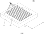
- FIG. 1 is a side view of a vibration sensor 001 according to some embodiments of this specification
- FIG. 2 is a front view of a vibration sensor 001 according to some embodiments of this specification
- FIG. 3 is a top view of a vibration sensor 001 according to some embodiments of this specification
- FIG. 4 is a right view of a vibration sensor 001 according to some embodiments of this specification
- FIG. 5 shows the sectional view A-A in FIG. 2 .
- the vibration sensor 001 may include a base 200 and a plurality of vibration beams 400.
- the base 200 may be a mounting base for the vibration sensor 001.
- Other components, such as the vibration beams 400, of the vibration sensor 001 may be connected to the base 200 directly or indirectly.
- the connection may be implemented in any manner, for example, a fixed connection manner such as welding, riveting, clamping, or bolting, or a deposition manner such as physical deposition (for example, physical vapor deposition) or chemical deposition (for example, chemical vapor deposition).
- the base 200 may be a structural body of any shape, for example, a regular-shaped structural body such as a cube, a cuboid, a cylinder, a prismoid, and a truncated cone, or any irregular-shaped structural body.
- a material of the base 200 may be Si, SiO 2 , SiNx, or the like.
- the base 200 may include a cavity 220.
- the cavity 220 may penetrate the base 200. In some embodiments, the cavity 220 may not penetrate the base 200. Referring to exemplary descriptions shown in FIG. 1 to FIG. 5 , the cavity 220 may penetrate an upper surface and a lower surface of the base 200.
- the cavity 220 may be one piece. In some embodiments, the cavity 220 may include a plurality of spaced sub-cavities. For ease of description, the cavity 220 shown in FIG. 1 to FIG. 5 is one piece. A person skilled in the art should understand that the cavity 220 including a plurality of spaced sub-cavities also falls within the protection scope of this specification.
- a dimension of the cavity 220 in a first direction 221 may vary along a second direction. That is, the dimension of the cavity 220 in the first direction 221 changes as its position in the second direction 222 changes. In other words, the cavity 220 has different dimensions in the first direction 221 at different positions of the cavity 220 in the second direction 222.
- the first direction 221 and the second direction 222 are not the same direction. That is, the first direction 221 and the second direction 222 form an angle. The angle may be an acute angle, a right angle, or an obtuse angle. In some embodiments, the first direction 221 is perpendicular to the second direction 222.
- a cross-sectional shape of the cavity 220 may be any shape that meets the foregoing conditions, such as a circle, an ellipse, a quadrilateral, a pentagon, a hexagon, a heptagon, an octagon, or even an irregular shape, such as a varied-curvature curve shape.
- the cavity 220 with different shapes may correspond to different first directions 221 and different second directions 222.
- the cross-sectional shape of the cavity 220 may be a quadrilateral, such as a square, the first direction 221 may be a direction of one diagonal of the square, and the second direction 222 may be a direction of the other diagonal of the square.
- the cross-sectional shape of the cavity 220 may be a rectangle, the first direction 221 may be a direction forming an acute angle with the length or width of the rectangle and the second direction 222 may be a direction perpendicular to the first direction.
- the cross-sectional shape of the cavity 220 may be a parallelogram, the first direction 221 may be a direction forming an acute angle with one side of the parallelogram, and the second direction 222 may be a direction perpendicular to the first direction.
- the cross-sectional shape of the cavity 220 may be a trapezoid, such as an isosceles trapezoid
- the second direction 222 may be a height direction of the isosceles trapezoid
- the first direction 221 may be a direction perpendicular to the second direction 222.
- the second direction 222 may alternatively be a direction forming an acute angle with a height direction of the isosceles trapezoid
- the first direction 221 may be a direction perpendicular to the second direction 222.
- the cross-sectional shape of the cavity 220 may alternatively be a right-angled trapezoid
- the second direction 222 may be a height direction of the right-angled trapezoid
- the first direction 221 may be a direction perpendicular to the second direction 222.
- the cross-sectional shape of the cavity 220 may alternatively be another quadrilateral, such as a trapezoid other than isosceles trapezoid and right-angled trapezoid, for example, a rhombus, a trapezium, and so on.
- the cross-sectional shape of the cavity 220 may be circular, the first direction 221 may be a direction of any diameter of the circular, and the second direction 222 may be a direction perpendicular to the first direction 221.
- the cross-sectional shape of the cavity 220 may be an ellipse, the first direction 221 may be a long-axis direction or a short-axis direction of the ellipse, and the second direction 222 may be a direction perpendicular to the first direction.
- the cross-sectional shape of the cavity 220 shown in FIG. 1 to FIG. 5 is an isosceles trapezoid, where the second direction 222 is a height direction of the isosceles trapezoid, and the first direction 221 and the second direction 222 are perpendicular to each other.
- the cavity 220 has different dimensions in the first direction 221 when the cavity 220 is at different positions in the second direction 222.
- a person skilled in the art should understand that the cavity 220 being another shape that meets the foregoing conditions also falls within the protection scope of this specification.
- An edge of the cavity 220 may be straight, curved, jagged, or the like. In some embodiments, the edge of the cavity 220 may be formed by straight lines.
- the dimension of the cavity 220 may be designed based on an application scenario of the vibration sensor 001 and a requirement for vibrational excitation. For example, the cavity 220 may have different dimensions when the vibration sensor 001 is used as an accelerometer and as an air-conduction microphone. In some embodiments, the dimension of the cavity 220 may be related to a dimension of the vibration beam 400, which will be described in detail in the following description.
- the vibration sensor 001 may include a plurality of vibration beams 400.
- the vibration beams 400 may be connected to the base 200, generate deformation in response to external vibrational excitation, and convert the deformation into a vibration signal.
- the vibration signal may be an electrical signal.
- the vibrational excitation may be air vibrational excitation directly acting on the vibration beams 400 or mechanical vibrational excitation acting on the base 200.
- the vibration beam 400 may be a plate-shaped structural body of any shape, for example, may be a rectangular beam, a trapezoidal beam, an L-shaped beam, a beam of another shape, or the like.
- the plurality of vibration beams 400 may be sequentially arranged on the base 200 along the second direction 222.
- the vibration beam 400 may be a clamped beam, that is, both ends of the vibration beam 400 may be connected to the base 200, and a middle portion may be suspended in the cavity 220.
- each vibration beam 400 may include a fixed terminal 420 and a movable terminal 440.
- each vibration beam 400 may further include a counterweight 460.
- the fixed terminal 420 may be located at both ends of the vibration beam 400 (that is, the fixed terminal may have two parts respectively located at two ends of the vibration beam).
- the fixed terminal 420 may be connected to the base 200 along the first direction 221. That is, both ends of the fixed terminal 420 may be distributed along the first direction 221.
- a distribution direction of both ends of the fixed terminal 420 is defined as a length direction, or an axial direction, of the vibration beam 400.
- the connection between the fixed terminal 420 and the base 200 may be implemented in any manner, for example, a fixed connection manner such as welding, riveting, clamping, or bolting, or a deposition manner such as physical deposition (for example, physical vapor deposition) or chemical deposition (for example, chemical vapor deposition).
- the fixed terminal 420 may be connected to the base 200 in an insulated manner.
- the fixed terminal 420 may be connected to the base 200 through an insulation layer.
- a material of the fixed terminal 420 may be Si, SiO 2 , SiNx, or the
- the fixed terminal 420 may be fixedly connected to an upper surface or a lower surface of the base 200 or an inner wall of the cavity 220.
- an example in which the fixed terminal 420 is connected to the upper surface of the base 200 is used for description.
- a person skilled in the art should understand that the fixed terminal 420 being connected to another position of the base 200 also falls within the protection scope of this specification.
- the movable terminal 440 may be connected to the fixed terminal 420, located between the fixed terminal 420 (that is, between the two arts of the fixed terminal), and suspended in the cavity 220. "Suspended in the cavity 220" may be suspended in, below, or above the cavity 220 of the base 200, without being in contact with the base 200. For ease of display, as shown in FIG. 1 to FIG. 5 , the movable terminal 440 may be suspended above the cavity 220, which is merely an exemplary description.
- the movable terminal 440 may generate deformation in response to the vibrational excitation, and convert the deformation into a vibration signal.
- the movable terminal 440 may include a piezoelectric sensing component 442 and a connecting beam 444.
- the piezoelectric sensing component 442 may convert the deformation of the movable terminal 440 into the vibration signal, and the vibration signal may include an electrical signal.
- the connecting beam 444 may be connected to the piezoelectric sensing component 442.
- the piezoelectric sensing component 442 may include a piezoelectric material.
- the vibration sensor 001 may receive external vibrational excitation, and convert the external vibrational excitation into an electrical signal.
- the external vibrational excitation may deform the movable terminal 440, causing the piezoelectric material in the piezoelectric sensing component 442 to deform, thereby generating stress and outputting a voltage.
- the external vibrational excitation is converted into an electrical signal, and the electrical signal is then collected and regulated through a back-end circuit to obtain a required electrical signal. All piezoelectric materials conform to a piezoelectric effect constitutive equation.
- the electrical displacement D i is mainly caused by the stress formed by the external vibrational excitation.
- a magnitude of an output electrical displacement D i of the piezoelectric material depends on a piezoelectric strain coefficient d ij of the material itself and the stress T j formed by the piezoelectric material during operation. After the piezoelectric material is determined, it is an effective measure to increase output of the piezoelectric sensing component 442 by designing a structure to increase stress in a partial region of an effective piezoelectric material.
- the piezoelectric sensing component 442 may be suspended in the cavity 220. In some embodiments, the piezoelectric sensing component 442 may be distributed over all regions of the movable terminal 440. In some embodiments, the piezoelectric sensing component 442 may be alternatively distributed over some regions of the movable terminal 440. The piezoelectric sensing component 442 may convert the deformation of the movable terminal 440 into a vibration signal, and output the vibration signal. When the movable terminal 440 moves relative to the base 200, deformation degrees at different positions of the movable terminal 440 may be different, and deformation stress on the piezoelectric sensing component 442 is also different.
- the piezoelectric sensing component 442 can be disposed at only a position, having a relatively high deformation degree and relatively large stress, of the movable terminal 440, thereby improving the sensitivity of the vibration sensor 001.
- the position, having a relatively high deformation degree and relatively large stress, of the movable terminal 440 is defined as a first region
- a position, having a relatively low deformation degree and relatively small stress, of the movable terminal 440 is defined as a second region.
- a voltage of the electrical signal in the first region is higher than a voltage of the electrical signal in the second region.
- the piezoelectric sensing component 442 can be disposed only in the first region. It should be noted that, the first region and the second region are regions corresponding to the movable terminal 440, and do not include a region of the fixed terminal 420, namely, a region at a junction between the vibration beam 400 and the base 200.
- a direction of the stress on the movable terminal 440 is related to an overall deformation direction of the movable terminal 440.
- the movable terminal 440 vibrates downwards and vibrates upwards, its deformation directions are opposite. In this case, directions of stress on a same portion of the movable terminal 440 are also opposite.
- a region under compressive stress during upward vibration is subjected to tensile stress in downward vibration, and a region under tensile stress during upward vibration is subjected to compressive stress in downward vibration.
- axial stress on a lower surface of the movable terminal 440 is symmetrical with respect to the center of the movable terminal 440, and tensile stress on the center side decreases to zero, and then increases from zero to compressive stress.
- the zero points are located at one-quarter and three-quarters of an axial length of the movable terminal 440.
- axial stress on a lower surface of the movable terminal 440 is symmetrical with respect to the center of the movable terminal 440, and compressive stress on the center side decreases to zero, and then increases from zero to the tensile stress.
- the zero points are located at one-quarter and three-quarters of the axial length of the movable terminal 440.
- the piezoelectric sensing component 442 may be arranged in a region where stress is relatively large and has a same direction. For ease of presentation, the following description is provided by using an example in which the movable terminal 440 vibrates downward. When the movable terminal 440 vibrates downward, in some embodiments, the piezoelectric sensing component 442 may be arranged in a region with a relatively large compressive stress.
- the piezoelectric sensing component 442 may be arranged at portions, close to the fixed terminal 420, on both ends of the movable terminal 440, and within a range in which a distance between the piezoelectric sensing component 442 and the fixed terminal 420 is less than a quarter of a length of the movable terminal 440. That is, the first region may be located at both ends of the movable terminal 440 and within a range in which a distance between the first region and the fixed terminal 420 is less than a quarter of the length of the movable terminal 440.
- the movable terminal 440 may include at least two piezoelectric sensing components 442. An example in which there are two piezoelectric sensing components 442 is used for description.
- the two piezoelectric sensing components 442 may be respectively close to both ends of the fixed terminal 420, and a distance between each piezoelectric sensing component 442 and an end, close to the piezoelectric sensing component 442, of the fixed terminal 420 may be less than 1/4 of the length of the movable terminal 440. In this case, both ends of each piezoelectric sensing component 442 are connected to the fixed terminal 420 and the connecting beam 444, respectively.
- the piezoelectric sensing component 442 when the movable terminal 440 vibrates downward, the piezoelectric sensing component 442 may be arranged in a region with a relatively large tensile stress.
- the piezoelectric sensing component 442 may be arranged on the movable terminal 440, and a distance between the piezoelectric sensing component 442 and one end of the fixed terminal 420 is within a range from one quarter to three quarters of the length of the movable terminal 440. That is, the first region may be on the movable terminal 440, and a distance between the first region and one end of the fixed terminal 420 is within a range from one quarter to three quarters of the length of the movable terminal 440.
- the distance between the piezoelectric sensing component 442 and the fixed terminal 420 may be a distance from any position on the piezoelectric sensing component 442 to the fixed terminal 420.
- the distance between the piezoelectric sensing component 442 and the fixed terminal 420 may be a distance between a center position of the piezoelectric sensing component 442 and the fixed terminal 420, or may be a distance between an end (any end) of the piezoelectric sensing component 442 and the fixed terminal 420, or may be a distance between another position of the piezoelectric sensing component 442 and the fixed terminal 420.
- the piezoelectric sensing component 442 may include at least one of a laminated structure composed of a piezoelectric single crystal structure(s) and a laminated structure composed of a piezoelectric twin structure(s). In some embodiments, the piezoelectric sensing component 442 may be the laminated structure composed of the piezoelectric single crystal structure.
- FIG. 6 is a schematic diagram showing that the piezoelectric sensing component 442 is a piezoelectric single crystal structure 442a according to some embodiments of this specification.
- the piezoelectric single crystal structure 442a may include an elastic layer 442a-2, a bottom electrode layer 442a-4, a piezoelectric layer 442a-6, and a top electrode layer 442a-8 in order from bottom to top along a thickness direction of the piezoelectric sensing component 442.
- the piezoelectric single crystal structure 442a may include an elastic layer 442a-2, a top electrode layer 442a-8, a piezoelectric layer 442a-6, and a bottom electrode layer 442a-4 in order from top to bottom along the thickness direction of the piezoelectric sensing component 442.
- the piezoelectric single crystal structure 442a includes the elastic layer 442a-2, the bottom electrode layer 442a-4, the piezoelectric layer 442a-6, and the top electrode layer 442a-8 in order from bottom to top along the thickness direction of the piezoelectric sensing component 442 is used for description.
- the piezoelectric single crystal structure 442a may further include a connection terminal layer 442a-9.
- the elastic layer 442a-2 may be fixedly connected to the fixed terminal 420 and the connecting beam 444 directly or indirectly.
- the connection may be implemented in any manner, for example, a fixed connection manner such as welding, riveting, clamping, or bolting, or a deposition manner such as physical deposition (for example, physical vapor deposition) or chemical deposition (for example, chemical vapor deposition).
- a fixed connection manner such as welding, riveting, clamping, or bolting
- a deposition manner such as physical deposition (for example, physical vapor deposition) or chemical deposition (for example, chemical vapor deposition).
- the elastic layer 442a-2 may generate deformation based on the vibrational excitation.
- the elastic layer 442a-2 may be made of a material that is easily deformed under action of an external force.
- the elastic layer 442a-2 may be of a structure that is easily deformed and made of a semiconductor material.
- the elastic layer 442a-2 may be a single-layer material, such as Si, SiO 2 , SiNx, or SiC, or may be a multi-layer material, such as Si/SiO 2 , SiO 2 /Si, Si/SiNx, or SiNx/Si.
- a thickness of the elastic layer 442a-2 may range from 1 ⁇ m to 10 ⁇ m. In some embodiments, the thickness of the elastic layer 442a-2 may range from 1 ⁇ m to 3 ⁇ m. In some embodiments, the thickness of the elastic layer 442a-2 may range from 2 ⁇ m to 6 ⁇ m. In some embodiments, the thickness of the elastic layer 442a-2 may range from 4 ⁇ m to 8 ⁇ m. In some embodiments, the thickness of the elastic layer 442a-2 may range from 6 ⁇ m to 10 ⁇ m.
- the piezoelectric sensing component 442 may include a piezoelectric layer 442a-6.
- the piezoelectric layer 442a-6 is a structure that may generate, under the action of an external force, a voltage on two end surfaces.
- the piezoelectric layer 442a-6 may be fixedly connected to the base 200 directly or indirectly.
- the connection may be implemented in any manner, for example, a fixed connection manner such as welding, riveting, clamping, or bolting, or a deposition manner such as physical deposition (for example, physical vapor deposition) or chemical deposition (for example, chemical vapor deposition).
- the piezoelectric layer 442a-6 may generate the deformation when receiving a vibration signal, and generate a voltage based on the deformation.
- the piezoelectric layer 442a-6 may be attached to a surface of the elastic layer 442a-2 directly or indirectly.
- the elastic layer 442a-2 may be connected to the fixed terminal 420 and the connecting beam 444, and the piezoelectric layer 442a-6 may be connected to the fixed terminal 420 and the connecting beam 444 through the elastic layer 442a-2.
- An example in which the vibration beam 400 is located on the upper surface of the base 200 is used for description.
- the piezoelectric layer 442a-6 may be located on a side, away from the base 200, of the elastic layer 442a-2.
- the piezoelectric layer 442a-6 may be located on a side, close to the base 200, of the elastic layer 442a-2.
- the elastic layer 442a-2 When the vibration beam 400 receives vibrational excitation from the outside, the elastic layer 442a-2 generates deformation based on the vibrational excitation. Based on a piezoelectric effect, the piezoelectric layer 442a-6 may be stressed under the action of the deformation of the elastic layer 442a-2, thereby generating a voltage (a potential difference).
- a beam structure with bending deformation includes a cantilever beam, a simply supported beam, a fixed/clamped beam, and the like.
- first-order bending deformation occurs on the beam structure, there is a neutral layer along a thickness direction, and materials on both sides of the neutral layer are in opposite stress states.
- a support arm material of a part above the neutral layer is in a state of tensile stress
- a support arm material of a part below the neutral layer is in a state of compressive stress.
- the piezoelectric layer 442a-6 needs to be arranged on one side of the neutral layer.
- a magnitude of the output electrical signal of the piezoelectric material is related to a magnitude of the stress.
- a distribution position of each layer of material in the thickness direction may affect stress distribution of each layer of material under same vibrational excitation.
- the piezoelectric layer 442a-6 may be distributed on a side of the elastic layer 442a-2. Specifically, the piezoelectric layer 442a-6 is distributed on a position close to an upper surface or a lower surface of the vibration beam 400 in the thickness direction, so that the piezoelectric layer 442a-6 is far away from the neutral layer and the stress of the piezoelectric layer 442a-6 is maximized.
- the piezoelectric layer 442a-6 may be a piezoelectric polymer thin film obtained according to a semiconductor deposition process (for example, magnetron sputtering or MOCVD).
- a material of the piezoelectric layer 442a-6 may include a piezoelectric crystal material and a piezoelectric ceramics material.
- the piezoelectric crystal material may be piezoelectric mono-crystal.
- the piezoelectric crystal material may include quartz, sphalerite, boracite, tourmaline, zincite, GaAs, barium titanate and derived crystal thereof, KH 2 PO 4 , NaKC 4 H 4 O 6 ⁇ 4H 2 O (rochelle salt), or any combination thereof.
- the piezoelectric ceramics material may be piezoelectric poly-crystal formed through irregular collection of fine grains that are obtained after solid-phase reaction and sintering between powder particles of different materials.
- the piezoelectric ceramics material may include barium titanate (BT), lead zirconate titanate (PZT), lithium lead barium niobate (PBLN), modified lead titanate (PT), aluminum nitride (AIN), zinc oxide (ZnO), or any combination thereof.
- the material of the piezoelectric layer 442a-6 may alternatively be a piezoelectric polymer material, for example, polyvinylidene fluoride (PVDF).
- a thickness of the piezoelectric layer 442a-6 may be greater than 500 nm. In some embodiments, the thickness of the piezoelectric layer 442a-6 may range from 20 ⁇ m to 500 ⁇ m, for example, when the vibration sensor 001 is used in a macroscopic device. In some embodiments, the thickness of the piezoelectric layer 442a-6 may range from 0.5 ⁇ m to 1.5 ⁇ m, for example, when the vibration sensor 001 is used in an MEMS device.
- a ratio of the thickness of the elastic layer 442a-2 to the thickness of the piezoelectric layer 442a-6 may be 1-10. In some embodiments, a ratio of the thickness of the elastic layer 442a-2 to the thickness of the piezoelectric layer 442a-6 may be 2-7.
- the bottom electrode layer 442a-4 and the top electrode layer 442a-8 may be respectively distributed on surfaces on both sides of the piezoelectric layer 442a-6.
- the piezoelectric layer 442a-6 may be disposed between the bottom electrode layer 442a-4 and the top electrode layer 442a-8.
- the piezoelectric layer 442a-6 may deform with the deformation of the elastic layer 442a-2 under the action of a vibrational excitation from the outside, and generate a voltage under the action of deformation stress.
- the bottom electrode layer 442a-4 and the top electrode layer 442a-8 may collect the voltage to generate the electrical signal.
- the bottom electrode layer 442a-4 is positionally aligned with the top electrode layer 442a-8.
- the piezoelectric layer 442a-6 is connected to the elastic layer 442a-2, and distributed on a side of the elastic layer 442a-2.
- the bottom electrode layer 442a-4 may be distributed between the piezoelectric layer 442a-6 and the elastic layer 442a-2, and the top electrode layer 442a-8 may be distributed on a side, away from the elastic layer 442a-2, of the piezoelectric layer 442a-6.
- the bottom electrode layer 442a-4 and the top electrode layer 442a-8 may be structures of a conductive material.
- the conductive material may include a metal, an alloy material, a metal oxide material, graphene, or the like, or any combination thereof.
- the metal and the alloy material may include nickel, iron, lead, platinum, titanium, copper, molybdenum, zinc, or any combination thereof.
- the alloy material may include a copper-zinc alloy, a copper-tin alloy, a copper-nickel-silicon alloy, a copper-chromium alloy, a copper-silver alloy, or any combination thereof.
- the metal oxide material may include RuO 2 , MnO 2 , PbO 2 , NiO, or the like, or any combination thereof.
- the bottom electrode layer 442a-4 may include at least one bottom piezoelectric electrode slice.
- the top electrode layer 442a-8 may include at least one top piezoelectric electrode slice.
- Each of the at least one bottom piezoelectric electrode slice may be positionally aligned with at least one of the at least one top piezoelectric electrode slice.
- each bottom piezoelectric electrode slice may positionally correspond to one top piezoelectric electrode slice.
- each bottom piezoelectric electrode slice may positionally correspond to a plurality of top piezoelectric electrode slices, for example, 2, 3, 4, or another quantity of top piezoelectric electrode slices.
- the plurality of top piezoelectric electrode slices may use the bottom piezoelectric electrode slice as a common terminal to form output units connected in series, thereby increasing an output voltage, and improving sensitivity.
- the plurality of top piezoelectric electrode slices may alternatively form output units connected in parallel with the bottom piezoelectric electrode slice, thereby increasing an output charge, and improving sensitivity.
- the piezoelectric sensing component 442 may include only output units connected in series, only output units connected in parallel, or both output units connected in series and output units connected in parallel.
- a thickness of the bottom electrode layer 442a-4 may range from 50 nm to 200 nm. In some embodiments, the thickness of the bottom electrode layer 442a-4 may range from 100 nm to 150 nm. In some embodiments, the thickness of the bottom electrode layer 442a-4 may range from 100 nm to 200 nm. In some embodiments, the thickness of the bottom electrode layer 442a-4 may range from 80 nm to 150 nm. In some embodiments, the thickness of the bottom electrode layer 442a-4 may range from 150 nm to 200 nm. In some embodiments, the thickness of the bottom electrode layer 442a-4 may range from 120 nm to 150 nm.
- the thickness of the bottom electrode layer 442a-4 may range from 120 nm to 200 nm. In some embodiments, the thickness of the bottom electrode layer 442a-4 may range from 150 nm to 200 nm. In some embodiments, a thickness of the top electrode layer 442a-8 may range from 50 nm to 200 nm. In some embodiments, the thickness of the top electrode layer 442a-8 may range from 100 nm to 150 nm. In some embodiments, the thickness of the top electrode layer 442a-8 may range from 100 nm to 200 nm. In some embodiments, the thickness of the top electrode layer 442a-8 may range from 80 nm to 150 nm.
- the thickness of the top electrode layer 442a-8 may range from 150 nm to 200 nm. In some embodiments, the thickness of the top electrode layer 442a-8 may range from 120 nm to 150 nm. In some embodiments, the thickness of the top electrode layer 442a-8 may range from 120 nm to 200 nm. In some embodiments, the thickness of the top electrode layer 442a-8 may range from 150 nm to 200 nm.
- the piezoelectric single crystal structure 442a may further include a connection terminal layer 442a-9, which is connected to the bottom electrode layer 442a-4 or the top electrode layer 442a-8, to output the electrical signal to an external processing circuit.
- the connection terminal layer 442a-9 may or may not be of a same material as the bottom electrode layer 442a-4 and the top electrode layer 442a-8.
- a thickness of the connection terminal layer 442a-9 may range from 100 nm to 200 nm.
- the thickness of the connection terminal layer 442a-9 may range from 150 nm to 200 nm.
- the thickness of the connection terminal layer 442a-9 may range from 100 nm to 150 nm.
- the thickness of the connection terminal layer 442a-9 may range from 120 nm to 200 nm.
- the thickness of the connection terminal layer 442a-9 may range from 160 nm to 200 nm.
- the piezoelectric sensing component 442 may be the laminated structure composed of the piezoelectric single crystal structure.
- FIG. 7 is a schematic diagram showing that the piezoelectric sensing component 442 is a piezoelectric twin structure 442b according to some embodiments of this specification.
- the piezoelectric twin structure 442b may include an electrode layer 442b-2, a piezoelectric layer 442b-4, an electrode layer 442b-2, a piezoelectric layer 442b-4, and an electrode layer 442b-2 in order from bottom to top along a thickness direction of the piezoelectric sensing component 442.
- the piezoelectric twin structure 442b may further include a connection terminal layer 442b-9.
- a material thickness of the electrode layer 442b-2 is basically the same as that of the bottom electrode layer 442a-4 or the top electrode layer 442a-8, and details are not described herein again.
- a material thickness of the piezoelectric layer 442b-4 is basically the same as that of the piezoelectric layer 442a-6, and details are not described herein again.
- a material thickness of the connection terminal layer 442b-9 is basically the same as that of the foregoing connection terminal layer 442a-9, and details are not described herein again.
- the connecting beam 444 may be used to connect piezoelectric sensing components 442.
- the connecting beam 444 may be located between two piezoelectric sensing components 442 and connect the two piezoelectric sensing components 442.
- a material of the connecting beam 444 may be Si, SiO 2 , SiNx, or the like.
- each vibration beam 400 may further include a counterweight 460.
- the counterweight 460 may be connected to the movable terminal 440.
- the counterweight 460 may be connected to the movable terminal 440 directly or indirectly. Specifically, the counterweight 460 may be connected to the connecting beam 444.
- the counterweight 460 may be located in the middle of the movable terminal 440, so that the counterweight 460 may be located in the center of the cavity 220 in the first direction 221.
- the counterweight 460 may be displaced based on the deformation.
- the counterweight 460 may protrude sideward relative to the movable terminal 440, and be suspended in the cavity 220.
- the counterweight 460 may protrude upwards relative to the movable terminal 440, and be suspended in the cavity 220.
- the counterweight 460 may alternatively protrude downwards relative to the movable terminal 440, and be suspended in the cavity 220.
- the counterweight 460 may make the movable terminal 440 more easily deformed under the action of an external force, thereby enhancing the electrical signal output by the piezoelectric sensing component 442.
- the electrical signal output by the piezoelectric sensing component 442 may be increased by changing a dimension, a shape, or a position of the counterweight 460. Natural frequency and vibration amplitude of the vibration beam 400 during vibration may be changed by disposing the counterweight 460.
- a material of the counterweight 460 may be Si, SiO 2 , SiNx, or the like.
- a planar shape of the counterweight 460 may be a circle, a triangle, a quadrangle, a polygon, or the like. An example in which the planar shape of the counterweight 460 is a quadrangle is used for description.
- a length of the counterweight 460 may range from 50 ⁇ m to 500 ⁇ m. In some embodiments, the length of the counterweight 460 may range from 80 ⁇ m to 300 ⁇ m. In some embodiments, a width of the counterweight 460 may range from 50 ⁇ m to 500 ⁇ m.
- the width of the counterweight 460 may range from 80 ⁇ m to 200 ⁇ m. In some embodiments, the width of the counterweight 460 may be greater than, equal to, or less than a width of the vibration beam 400. In some embodiments, the width of the counterweight 460 may be equal to the width of the vibration beam 400.
- a piezoelectric sensing component 442 may be additionally added near the counterweight 460.
- the additionally added piezoelectric sensing component 442 may be disposed in a circumferential region close to the counterweight 460 and around the counterweight 460.
- each vibration beam 400 may include a counterweight 460.
- each vibration beam 400 may not include a counterweight 460.
- the dimension of the cavity 220 in the first direction 221 may vary along the second direction 222. That is, the dimension of the cavity 220 in the first direction 221 changes as its position in the second direction 222 changes. In other words, the cavity 220 has different dimensions in the first direction 221 when the cavity 220 is at different positions in the second direction 222.
- the plurality of vibration beams 400 may be sequentially arranged on the base 200 along the second direction 222.
- the movable terminal 440 of each vibration beam 400 is suspended in the cavity 220. In other words, the plurality of vibration beams 400 can be respectively located at different positions, in the second direction 222, of the cavity 220.
- each vibration beam 400 has a different natural frequency.
- the plurality of vibration beams 400 correspond to a plurality of vibration frequencies.
- Each vibration beam 400 generates, in response to external vibrational excitation, a vibration signal in a sub-target frequency window including a natural frequency corresponding to the vibration beam.
- the vibration signals generated by different vibration beams 400 correspond to different sub-target frequency windows.
- a plurality of sub-target frequency windows corresponding to the plurality of vibration beams 400 cover different frequency ranges, and the plurality of sub-target frequency windows constitute a target frequency window.
- the target frequency window may be a consecutive frequency window.
- the plurality of sub-target frequency windows together can constitute a continuous target frequency window.
- the target frequency window may be any frequency range.
- the target frequency window may be set based on a usage scenario of the vibration sensor 001.
- the target frequency window may be different for the vibration sensor 001 used as a microphone and as an acceleration sensor.
- a plurality of natural frequencies corresponding to the plurality of vibration beams 400 may be evenly distributed within the target frequency window.
- the plurality of natural frequencies corresponding to the plurality of vibration beams 400 may not be evenly distributed within the target frequency window.
- the sub-target frequency window may be a frequency window including the natural frequency.
- the sub-target frequency window may be a frequency window set symmetrically with respect to the natural frequency.
- the sub-target frequency window may be a frequency window set asymmetrically with respect to the natural frequency.
- a length range of the sub-target frequency window should be within a preset length range.
- a range covered by the sub-target frequency window may be determined based on an amplitude of a vibration signal corresponding to the sub-target frequency window. For example, the amplitude of the vibration signal in the sub-target frequency window should not be less than a preset proportion of a resonance peak corresponding to the natural frequency.
- the preset proportion may be any preset proportion, such as 20%, 30%, and 50%.
- the range covered by the sub-target frequency window may be determined based on sensitivity of the vibration signal corresponding to the sub-target frequency window. For example, the sensitivity of the vibration signal in the sub-target frequency window should not be less than a preset threshold.
- a range of a target frequency window corresponding to the vibration sensor 001 may be determined according to a usage scenario and usage requirements of the vibration sensor 001, so as to determine a quantity of the plurality of vibration beams 400, and a natural frequency and a sub-target frequency window that are corresponding to each vibration beam 400.
- the target frequency window may range from 100 Hz to 5000 Hz.
- the target frequency window of the vibration sensor 001 may range from 20 Hz to 5000 Hz.
- the quantity of the vibration beams 400 may range from 3 to 50.
- the quantity of the vibration beams 400 may range from 10 to 20. In some embodiments, the quantity of the vibration beams 400 may be determined according to a usage scenario and usage requirements of the vibration sensor 001 and based on a quantity of resonance peaks required by the vibration sensor 001. In a case where only first-order resonance peaks of the vibration beams 400 are used, the quantity of vibration beams 400 is equal to the quantity of resonance peaks. In a case where high-order resonance peaks of the vibration beams 400 are used, the quantity of vibration beams 400 is less than the quantity of resonance peaks. However, a signal strength of a high-order resonance peak is usually much less than that of a first-order resonance peak, so that the first-order resonance peak of the vibration beam 400 is usually used in the vibration sensor 001.
- the natural frequency of the vibration beam 400 is determined by characteristics of the vibration beam 400.
- the natural frequency of the vibration beam 400 is not only related to a material property of the vibration beam 400, but also related to a dimension of the movable terminal 440, suspended in the cavity 200, of the vibration beam 400.
- the cavity 220 has different dimensions in the first direction 221 when the cavity 220 is at different positions in the second direction 222. Therefore, each vibration beam 400 may be designed based on a dimension of the cavity 220 in the first direction 221, a connection position of each vibration beam 400 on the cavity 220, and a dimension of each vibration beam 400, so that a natural frequency of each vibration beam 400 satisfies a preset value.
- the movable terminal 440 of each vibration beam 400 suspended in the cavity 220 satisfies a preset rule by changing the dimension of the cavity 220 in the first direction 221, the connection position of each vibration beam 400 on the cavity 220, and the dimension of each vibration beam 400, so that the natural frequency of each vibration beam 400 satisfies the preset value.
- the preset value may be a predetermined natural frequency of each vibration beam 400.
- overall dimensions of the plurality of vibration beams 400 may be the same.
- the vibration beams 400 may have a same axial length, a same width, and a same thickness.
- the movable terminals 440, suspended in the cavity 220, of the plurality of vibration beams 400 may have different dimensions by changing a connection position of each vibration beam 400 on the cavity 220 and a dimension of the cavity 220 in the first direction 221, so that the plurality of vibration beams 400 have different natural frequencies, and the natural frequencies satisfies the preset value. In this case, there is no need to customize the dimension of each vibration beam 400.
- a design of the natural frequencies of the plurality of vibration beams 400 may be realized and the natural frequencies satisfies the preset value only by changing the dimension of the cavity 220 and the connection position of each vibration beam 400 on the cavity 220. This method may reduce a processing difficulty and processing costs, and also improve precision of the vibration sensor 001.
- the overall dimensions of the plurality of vibration beams 400 may be different. For example, dimensions in at least one direction of the axial length, width, and thickness of the vibration beams 400 may be different.
- the movable terminals 440, suspended in the cavity 220, of the plurality of vibration beams 400 may have different dimensions by changing a connection position of each vibration beam 400 on the cavity 220, a dimension of the cavity 220 in the first direction 221, and dimensions of the plurality of vibration beams 400, so that the plurality of vibration beams 400 have different natural frequencies, and the natural frequencies satisfies the preset value.
- the target frequency window ranges from 20 Hz to 5000 Hz
- a quantity of the vibration beams 400 is 10, and natural frequencies of the 10 vibration beams 400 are evenly distributed in the target frequency window is used for description.
- a frequency band width is required between the natural frequencies of the vibration beams 400 for differentiation, and the frequency band width between the natural frequencies may range from 50 Hz to 400 Hz.
- the frequency band width between the natural frequencies may range from 100 Hz to 200 Hz.
- a gap width between the vibration beams 400 may range from 1 ⁇ m to 200 ⁇ m.
- the gap width between the vibration beams 400 may range from 10 ⁇ m to 100 ⁇ m.
- the gap widths between different vibration beams 400 may or may not be equal.
- a length of the movable terminal 440, suspended above the cavity 220, of each vibration beam 400 in the first direction 221 may vary linearly or non-linearly.
- the vibration beams 400 may be arranged in sequence on the cavity 220 according to the length of the movable terminal 440, or may be arranged according to another rule.
- a planar shape of each vibration beam 400 may be a rectangle, a trapezoid, a curve, or the like.
- a cross-sectional width of each vibration beam 400 may range from 50 ⁇ m to 300 ⁇ m.
- the cross-sectional width of each vibration beam 400 may range from 80 ⁇ m to 200 ⁇ m.
- an axial length of each vibration beam 400 may range from 100 ⁇ m to 1300 ⁇ m. In some embodiments, the axial length of each vibration beam 400 may range from 200 ⁇ m to 1200 ⁇ m.
- the vibration beam 400 may not include a counterweight 460.
- a counterweight 460 For example, in an air-conduction microphone, since energy of air vibrational excitation is small, gap widths between adjacent vibration beams 400 may be reduced to increase an output of a vibration signal.
- the vibration beam 400 may further include a counterweight 460.
- each vibration beam 400 may be designed based on a dimension of the cavity 220 in the first direction 221, a connection position of each vibration beam 400 on the cavity 220, a dimension of each vibration beam 400, and a dimension of the counterweight 460, so that a natural frequency of each vibration beam 400 satisfies a preset value.
- the movable terminal 440 of each vibration beam 400 suspended in the cavity 220 may satisfy a preset rule by changing the dimension of the cavity 220 in the first direction 221, the connection position of each vibration beam 400 on the cavity 220, the dimension of each vibration beam 400, and the dimension of the counterweight 460, so that the natural frequency of each vibration beam 400 satisfies the preset value.
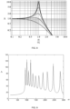
- FIG. 8 is a normalized displacement resonance graph according to some embodiments of this specification.
- the graph shown in FIG. 8 may be a normalized displacement resonance graph corresponding to one of a plurality of vibration beams 400.
- a horizontal axis is a ratio of external vibrational excitation ⁇ to a natural frequency ⁇ 0 of the vibration beam 400
- a vertical axis is a normalized displacement A.
- the normalized displacement A may be a ratio of a displacement amplitude to a static displacement amplitude of the vibration beam 400.
- M is a mass of the vibration beam 400, namely, a mass of a movable terminal 440 and a counterweight 460; and K is an elastic coefficient of the vibration beam 400.
- the normalized displacement A reaches the maximum, that is, a displacement at resonance frequency reaches a peak value (namely, a resonance peak).
- a preset frequency range near the natural frequency ⁇ 0 of the vibration beam 400 may be selected as a sub-target frequency window corresponding to each vibration beam 400, and a vibration signal in the sub-target frequency window may be used as a vibration signal generated by the vibration beam 400.
- Q ⁇ 0 M R
- R denotes a damping of the vibration beam 400.
- FIG. 9 is a schematic diagram of a vibration signal according to some embodiments of this specification. The vibration signal shown in FIG. 9 is obtained through linear superposition of a plurality of vibration signals generated by a plurality of vibration beams 400.
- a deviation of each vibration signal output by different vibration beams 400 may be within a preset deviation range on a natural frequency corresponding to the vibration signal, so that each vibration signal output by different vibration beams 400 may be in a same or similar order of magnitude on the natural frequency corresponding to the vibration signal to facilitate calculation.
- the preset deviation range may be a preset range that is convenient for signal calculation.
- the preset deviation range may be obtained based on experience, may be obtained based on experimental statistics, or may be obtained based on machine learning.
- the deviation of each vibration signal output by different vibration beams 400 being within a preset deviation range on a natural frequency corresponding to the vibration signal may be that a deviation of a normalized displacement A of the vibration signals output by the different vibration beams 400 does not exceed the preset deviation range on the corresponding natural frequency.
- the preset deviation range may be any value, such as ⁇ 30%, ⁇ 20%, or ⁇ 10%.
- a mechanical quality factor Q of each vibration beam 400 may be designed, so that a deviation of each mechanical quality factor Q of the plurality of vibration beams 400 is within a preset deviation range, and thus the deviation of the normalized displacement A of the vibration signals output by the different vibration beams 400 is within the preset deviation range on the corresponding natural frequency.
- the counterweight 460 may be matched with the natural frequency of the vibration beam 400 corresponding to the counterweight 460 by designing a dimension of the counterweight 460, so that the deviation of the mechanical quality factor Q of each vibration beam 400 is within the preset deviation range, and thus a deviation of the vibration signal corresponding to each vibration beam 400 is within the preset deviation range on the corresponding natural frequency.
- the deviation of the mechanical quality factor Q of each vibration beam 400 may be within the preset deviation range by designing and changing the dimension of the cavity 220 in the first direction 221, the connection position of each vibration beam 400 on the cavity 220, the dimension of the movable terminal 440, and the dimension of the counterweight 460, so that the deviation of the vibration signal corresponding to each vibration beam 400 is within the preset deviation range on the natural frequency corresponding to the vibration beam 400.
- the deviation of the normalized displacement A of the vibration signals output by different vibration beams 400 may alternatively be not within the preset deviation range on the corresponding natural frequencies.
- the normalized displacement A of the vibration signals output by different vibration beams 400 being not within the preset deviation range on the corresponding natural frequencies does not affect superposition processing of the vibration signals, which also falls within the protection scope of this specification.
- the microphone may include a housing and the vibration sensor 001 provided in this specification.
- the vibration sensor 001 may be mounted in the housing.
- the housing may be fixedly connected to the base 200.
- the housing and the base 200 may be integrated, or may be formed separately and fixedly connected in a manner such as welding, riveting, bolting, or bonding.
- the piezoelectric sensing component 442 may convert the deformation into the vibration signal, and output the vibration signal.
- the microphone may further include a signal synthesizing circuit.
- the signal synthesizing circuit may be connected to the piezoelectric sensing component 442 of each vibration beam 400 and configured to collect the vibration signal of each piezoelectric sensing component 442 during operation and perform signal synthesis processing, to generate a vibration signal within a target frequency window.
- the signal synthesis processing may refer to performing linear superposition on a plurality of vibration signals generated by the plurality of vibration beams 400.
- the microphone described in this specification may be applied to various electronic products, such as earphones (for example, bone-conduction earphones or air-conduction earphones, wireless earphones, or wired earphones), smart glasses, a smart wearable device, a smart helmet, a smart watch, or another device that has a voice collection function.
- earphones for example, bone-conduction earphones or air-conduction earphones, wireless earphones, or wired earphones
- smart glasses for example, a bone-conduction earphones or air-conduction earphones, wireless earphones, or wired earphones
- smart glasses for example, a smart glasses, a smart wearable device, a smart helmet, a smart watch, or another device that has a voice collection function.
- a vibration beam 400 is fixed on a base 200 through a fixed terminal 420 at both ends, and a movable terminal 440 of a middle portion is suspended in a cavity 220 and generates deformation in response to external vibrational excitation.
- portions, suspended in the cavity 220, of a plurality of vibration beams 400 may have different dimensions by changing a structure and a dimension of the cavity 220 and a dimension and a connection position of each vibration beam 400, so that different vibration beams 400 may have different natural frequencies, and resonance peaks of different frequencies may be generated under vibrational excitation.
- the plurality of vibration beams 400 may generate a vibration signal with a plurality of different frequency ranges, and the vibration signal with the plurality of different frequency ranges may together constitute a vibration signal with a wide frequency band, making the vibration sensor 001 have a wider frequency response range.
- a vibration signal selected by the vibration sensor 001 and the microphone may be a vibration signal within a preset range near the resonance peak, so that sensitivity may be higher.
- a dimension of the cavity 220 of the base 200 may be designed to realize multi-resonance peaks and a wide frequency band.
- the structure may be simple, processing difficulty may be low, processing costs may be low, and a more accurate collection result of the vibration signal may be obtained.
- a displacement signal output at different frequencies with a steep cut-off edge may be extracted from the vibration signal shown in FIG. 9 by using a low-order filter during later algorithm processing, so that input signals in different frequencies are extracted, thereby avoiding use of a high-order filter for extracting the signals in later algorithm and reducing a calculation amount of the algorithm.
Landscapes
- Engineering & Computer Science (AREA)
- Physics & Mathematics (AREA)
- Acoustics & Sound (AREA)
- Signal Processing (AREA)
- Computer Hardware Design (AREA)
- Microelectronics & Electronic Packaging (AREA)
- Measurement Of Mechanical Vibrations Or Ultrasonic Waves (AREA)
Applications Claiming Priority (1)
| Application Number | Priority Date | Filing Date | Title |
|---|---|---|---|
| PCT/CN2022/094006 WO2023221069A1 (zh) | 2022-05-20 | 2022-05-20 | 振动传感器以及麦克风 |
Publications (2)
| Publication Number | Publication Date |
|---|---|
| EP4408020A1 true EP4408020A1 (de) | 2024-07-31 |
| EP4408020A4 EP4408020A4 (de) | 2025-01-08 |
Family
ID=88834330
Family Applications (1)
| Application Number | Title | Priority Date | Filing Date |
|---|---|---|---|
| EP22942109.4A Pending EP4408020A4 (de) | 2022-05-20 | 2022-05-20 | Vibrationssensor und mikrofon |
Country Status (4)
| Country | Link |
|---|---|
| US (1) | US20240268233A1 (de) |
| EP (1) | EP4408020A4 (de) |
| CN (1) | CN118120258A (de) |
| WO (1) | WO2023221069A1 (de) |
Family Cites Families (7)
| Publication number | Priority date | Publication date | Assignee | Title |
|---|---|---|---|---|
| JPH08265887A (ja) * | 1995-03-23 | 1996-10-11 | Mitsubishi Electric Corp | 骨伝導マイクおよび骨伝導イヤホンマイク |
| CN201216021Y (zh) * | 2008-05-16 | 2009-04-01 | 东莞泉声电子有限公司 | 数字接触式振动拾音器 |
| KR102207928B1 (ko) * | 2014-08-13 | 2021-01-26 | 삼성전자주식회사 | 음향 센싱 소자 및 주파수 정보 획득 방법 |
| US9661411B1 (en) * | 2015-12-01 | 2017-05-23 | Apple Inc. | Integrated MEMS microphone and vibration sensor |
| EP3909261A4 (de) * | 2019-01-11 | 2022-10-12 | Hemideina Pty Ltd | Akustische vorrichtungen |
| CN111050256A (zh) * | 2019-12-17 | 2020-04-21 | 武汉大学 | 一种小型化的高灵敏度压电式麦克风 |
| KR20220022945A (ko) * | 2020-08-19 | 2022-03-02 | 삼성전자주식회사 | 지향성 음향 센서 |
-
2022
- 2022-05-20 CN CN202280070393.6A patent/CN118120258A/zh active Pending
- 2022-05-20 WO PCT/CN2022/094006 patent/WO2023221069A1/zh not_active Ceased
- 2022-05-20 EP EP22942109.4A patent/EP4408020A4/de active Pending
-
2024
- 2024-04-18 US US18/639,803 patent/US20240268233A1/en active Pending
Also Published As
| Publication number | Publication date |
|---|---|
| US20240268233A1 (en) | 2024-08-08 |
| EP4408020A4 (de) | 2025-01-08 |
| WO2023221069A1 (zh) | 2023-11-23 |
| CN118120258A (zh) | 2024-05-31 |
Similar Documents
| Publication | Publication Date | Title |
|---|---|---|
| US12114129B2 (en) | Bone conduction microphone | |
| CN114697837B (zh) | 一种骨传导传声装置 | |
| US20230300536A1 (en) | Vibration sensor and microphone | |
| US12185045B2 (en) | Microphone with low noise and high Q value | |
| CN115086815B (zh) | 振动传感器以及麦克风 | |
| EP4408020A1 (de) | Vibrationssensor und mikrofon | |
| TWI852052B (zh) | 傳聲器 | |
| US11540058B1 (en) | Microphone with additional piezoelectric component for energy harvesting | |
| CN114697822A (zh) | 一种传声器装置 | |
| CN117135550A (zh) | 振动传感器以及麦克风 | |
| RU2802593C1 (ru) | Микрофон костной проводимости | |
| HK40079369A (en) | Vibration sensor and microphone | |
| HK40047882B (zh) | 一种传声器装置 |
Legal Events
| Date | Code | Title | Description |
|---|---|---|---|
| STAA | Information on the status of an ep patent application or granted ep patent |
Free format text: STATUS: THE INTERNATIONAL PUBLICATION HAS BEEN MADE |
|
| PUAI | Public reference made under article 153(3) epc to a published international application that has entered the european phase |
Free format text: ORIGINAL CODE: 0009012 |
|
| STAA | Information on the status of an ep patent application or granted ep patent |
Free format text: STATUS: REQUEST FOR EXAMINATION WAS MADE |
|
| 17P | Request for examination filed |
Effective date: 20240422 |
|
| AK | Designated contracting states |
Kind code of ref document: A1 Designated state(s): AL AT BE BG CH CY CZ DE DK EE ES FI FR GB GR HR HU IE IS IT LI LT LU LV MC MK MT NL NO PL PT RO RS SE SI SK SM TR |
|
| REG | Reference to a national code |
Ref country code: DE Ref legal event code: R079 Free format text: PREVIOUS MAIN CLASS: H04R0001220000 Ipc: H04R0017100000 |
|
| A4 | Supplementary search report drawn up and despatched |
Effective date: 20241206 |
|
| RIC1 | Information provided on ipc code assigned before grant |
Ipc: H04R 17/02 20060101ALN20241202BHEP Ipc: H04R 1/24 20060101ALN20241202BHEP Ipc: B81B 3/00 20060101ALI20241202BHEP Ipc: H04R 1/22 20060101ALI20241202BHEP Ipc: H04R 17/10 20060101AFI20241202BHEP |
|
| DAV | Request for validation of the european patent (deleted) | ||
| DAX | Request for extension of the european patent (deleted) |