EP4407776A1 - Verbinder, batteriepack und elektrische vorrichtung - Google Patents
Verbinder, batteriepack und elektrische vorrichtung Download PDFInfo
- Publication number
- EP4407776A1 EP4407776A1 EP22874497.5A EP22874497A EP4407776A1 EP 4407776 A1 EP4407776 A1 EP 4407776A1 EP 22874497 A EP22874497 A EP 22874497A EP 4407776 A1 EP4407776 A1 EP 4407776A1
- Authority
- EP
- European Patent Office
- Prior art keywords
- insulator
- connecting portion
- along
- projection
- connector
- Prior art date
- Legal status (The legal status is an assumption and is not a legal conclusion. Google has not performed a legal analysis and makes no representation as to the accuracy of the status listed.)
- Pending
Links
Images


Classifications
-
- H—ELECTRICITY
- H01—ELECTRIC ELEMENTS
- H01M—PROCESSES OR MEANS, e.g. BATTERIES, FOR THE DIRECT CONVERSION OF CHEMICAL ENERGY INTO ELECTRICAL ENERGY
- H01M10/00—Secondary cells; Manufacture thereof
- H01M10/42—Methods or arrangements for servicing or maintenance of secondary cells or secondary half-cells
- H01M10/425—Structural combination with electronic components, e.g. electronic circuits integrated to the outside of the casing
-
- H—ELECTRICITY
- H01—ELECTRIC ELEMENTS
- H01M—PROCESSES OR MEANS, e.g. BATTERIES, FOR THE DIRECT CONVERSION OF CHEMICAL ENERGY INTO ELECTRICAL ENERGY
- H01M50/00—Constructional details or processes of manufacture of the non-active parts of electrochemical cells other than fuel cells, e.g. hybrid cells
- H01M50/50—Current conducting connections for cells or batteries
-
- H—ELECTRICITY
- H01—ELECTRIC ELEMENTS
- H01M—PROCESSES OR MEANS, e.g. BATTERIES, FOR THE DIRECT CONVERSION OF CHEMICAL ENERGY INTO ELECTRICAL ENERGY
- H01M50/00—Constructional details or processes of manufacture of the non-active parts of electrochemical cells other than fuel cells, e.g. hybrid cells
- H01M50/10—Primary casings; Jackets or wrappings
- H01M50/102—Primary casings; Jackets or wrappings characterised by their shape or physical structure
- H01M50/105—Pouches or flexible bags
-
- H—ELECTRICITY
- H01—ELECTRIC ELEMENTS
- H01M—PROCESSES OR MEANS, e.g. BATTERIES, FOR THE DIRECT CONVERSION OF CHEMICAL ENERGY INTO ELECTRICAL ENERGY
- H01M50/00—Constructional details or processes of manufacture of the non-active parts of electrochemical cells other than fuel cells, e.g. hybrid cells
- H01M50/10—Primary casings; Jackets or wrappings
- H01M50/172—Arrangements of electric connectors penetrating the casing
- H01M50/174—Arrangements of electric connectors penetrating the casing adapted for the shape of the cells
- H01M50/178—Arrangements of electric connectors penetrating the casing adapted for the shape of the cells for pouch or flexible bag cells
-
- H—ELECTRICITY
- H01—ELECTRIC ELEMENTS
- H01M—PROCESSES OR MEANS, e.g. BATTERIES, FOR THE DIRECT CONVERSION OF CHEMICAL ENERGY INTO ELECTRICAL ENERGY
- H01M50/00—Constructional details or processes of manufacture of the non-active parts of electrochemical cells other than fuel cells, e.g. hybrid cells
- H01M50/20—Mountings; Secondary casings or frames; Racks, modules or packs; Suspension devices; Shock absorbers; Transport or carrying devices; Holders
- H01M50/204—Racks, modules or packs for multiple batteries or multiple cells
- H01M50/207—Racks, modules or packs for multiple batteries or multiple cells characterised by their shape
- H01M50/211—Racks, modules or packs for multiple batteries or multiple cells characterised by their shape adapted for pouch cells
-
- H—ELECTRICITY
- H01—ELECTRIC ELEMENTS
- H01M—PROCESSES OR MEANS, e.g. BATTERIES, FOR THE DIRECT CONVERSION OF CHEMICAL ENERGY INTO ELECTRICAL ENERGY
- H01M50/00—Constructional details or processes of manufacture of the non-active parts of electrochemical cells other than fuel cells, e.g. hybrid cells
- H01M50/20—Mountings; Secondary casings or frames; Racks, modules or packs; Suspension devices; Shock absorbers; Transport or carrying devices; Holders
- H01M50/284—Mountings; Secondary casings or frames; Racks, modules or packs; Suspension devices; Shock absorbers; Transport or carrying devices; Holders with incorporated circuit boards, e.g. printed circuit boards [PCB]
-
- H—ELECTRICITY
- H01—ELECTRIC ELEMENTS
- H01M—PROCESSES OR MEANS, e.g. BATTERIES, FOR THE DIRECT CONVERSION OF CHEMICAL ENERGY INTO ELECTRICAL ENERGY
- H01M50/00—Constructional details or processes of manufacture of the non-active parts of electrochemical cells other than fuel cells, e.g. hybrid cells
- H01M50/50—Current conducting connections for cells or batteries
- H01M50/502—Interconnectors for connecting terminals of adjacent batteries; Interconnectors for connecting cells outside a battery casing
- H01M50/503—Interconnectors for connecting terminals of adjacent batteries; Interconnectors for connecting cells outside a battery casing characterised by the shape of the interconnectors
-
- H—ELECTRICITY
- H01—ELECTRIC ELEMENTS
- H01M—PROCESSES OR MEANS, e.g. BATTERIES, FOR THE DIRECT CONVERSION OF CHEMICAL ENERGY INTO ELECTRICAL ENERGY
- H01M50/00—Constructional details or processes of manufacture of the non-active parts of electrochemical cells other than fuel cells, e.g. hybrid cells
- H01M50/50—Current conducting connections for cells or batteries
- H01M50/502—Interconnectors for connecting terminals of adjacent batteries; Interconnectors for connecting cells outside a battery casing
- H01M50/514—Methods for interconnecting adjacent batteries or cells
- H01M50/516—Methods for interconnecting adjacent batteries or cells by welding, soldering or brazing
-
- H—ELECTRICITY
- H01—ELECTRIC ELEMENTS
- H01M—PROCESSES OR MEANS, e.g. BATTERIES, FOR THE DIRECT CONVERSION OF CHEMICAL ENERGY INTO ELECTRICAL ENERGY
- H01M50/00—Constructional details or processes of manufacture of the non-active parts of electrochemical cells other than fuel cells, e.g. hybrid cells
- H01M50/50—Current conducting connections for cells or batteries
- H01M50/543—Terminals
- H01M50/552—Terminals characterised by their shape
- H01M50/553—Terminals adapted for prismatic, pouch or rectangular cells
- H01M50/557—Plate-shaped terminals
-
- H—ELECTRICITY
- H01—ELECTRIC ELEMENTS
- H01M—PROCESSES OR MEANS, e.g. BATTERIES, FOR THE DIRECT CONVERSION OF CHEMICAL ENERGY INTO ELECTRICAL ENERGY
- H01M50/00—Constructional details or processes of manufacture of the non-active parts of electrochemical cells other than fuel cells, e.g. hybrid cells
- H01M50/50—Current conducting connections for cells or batteries
- H01M50/572—Means for preventing undesired use or discharge
- H01M50/584—Means for preventing undesired use or discharge for preventing incorrect connections inside or outside the batteries
- H01M50/588—Means for preventing undesired use or discharge for preventing incorrect connections inside or outside the batteries outside the batteries, e.g. incorrect connections of terminals or busbars
-
- H—ELECTRICITY
- H01—ELECTRIC ELEMENTS
- H01M—PROCESSES OR MEANS, e.g. BATTERIES, FOR THE DIRECT CONVERSION OF CHEMICAL ENERGY INTO ELECTRICAL ENERGY
- H01M50/00—Constructional details or processes of manufacture of the non-active parts of electrochemical cells other than fuel cells, e.g. hybrid cells
- H01M50/50—Current conducting connections for cells or batteries
- H01M50/572—Means for preventing undesired use or discharge
- H01M50/584—Means for preventing undesired use or discharge for preventing incorrect connections inside or outside the batteries
- H01M50/59—Means for preventing undesired use or discharge for preventing incorrect connections inside or outside the batteries characterised by the protection means
-
- H—ELECTRICITY
- H01—ELECTRIC ELEMENTS
- H01M—PROCESSES OR MEANS, e.g. BATTERIES, FOR THE DIRECT CONVERSION OF CHEMICAL ENERGY INTO ELECTRICAL ENERGY
- H01M10/00—Secondary cells; Manufacture thereof
- H01M10/42—Methods or arrangements for servicing or maintenance of secondary cells or secondary half-cells
- H01M10/425—Structural combination with electronic components, e.g. electronic circuits integrated to the outside of the casing
- H01M2010/4271—Battery management systems including electronic circuits, e.g. control of current or voltage to keep battery in healthy state, cell balancing
-
- Y—GENERAL TAGGING OF NEW TECHNOLOGICAL DEVELOPMENTS; GENERAL TAGGING OF CROSS-SECTIONAL TECHNOLOGIES SPANNING OVER SEVERAL SECTIONS OF THE IPC; TECHNICAL SUBJECTS COVERED BY FORMER USPC CROSS-REFERENCE ART COLLECTIONS [XRACs] AND DIGESTS
- Y02—TECHNOLOGIES OR APPLICATIONS FOR MITIGATION OR ADAPTATION AGAINST CLIMATE CHANGE
- Y02E—REDUCTION OF GREENHOUSE GAS [GHG] EMISSIONS, RELATED TO ENERGY GENERATION, TRANSMISSION OR DISTRIBUTION
- Y02E60/00—Enabling technologies; Technologies with a potential or indirect contribution to GHG emissions mitigation
- Y02E60/10—Energy storage using batteries
Definitions
- This application relates to the technical field of energy storage, and in particular, to a connector, a battery pack, and an electrical device.
- tabs of a plurality of battery cells are usually passed through a current collecting plate and connected to a sampling terminal on the current collecting plate to implement series connection of pouch cells, and are connected to the current collecting plate by a voltage sensing harness to collect voltage, thereby involving use of many materials and a high production cost.
- the connector includes a first insulator and a second insulator disposed along a first direction, and a plurality of conductive pieces spaced apart from each other are disposed between the first insulator and the second insulator.
- Each conductive piece includes a first connecting portion and a second connecting portion. Both the first connecting portion and the second connecting portion are configured to be connected to other conductive pieces.
- the second connecting portions of the plurality of conductive pieces are spaced apart along a second direction.
- One conductive piece is connected to other conductive pieces by the first connecting portion and the second connecting portion, thereby avoiding the need of a current collecting plate, a sampling terminal, and a voltage sensing harness, and reducing the number of materials that need to be used.
- the second direction is perpendicular to the first direction.
- the third connecting portion includes a third connecting sub-portion.
- the third connecting sub-portion is bent toward a side of the first insulator along the second direction.
- the third connecting sub-portion is connected to the second connecting portion.
- the bent third connecting sub-portion increases the distance between the adjacent second connecting portions, reduces the risk of a short circuit caused by the touch between the adjacent second connecting portions, and facilitates welding between the second connecting portion and the circuit board.
- the first insulator is provided with a plurality of first openings.
- the second insulator is provided with a plurality of second openings. along the first direction, a projection of the plurality of first openings at least partially overlaps with a projection of the plurality of second openings.
- the projection of the plurality of second openings is located inside the projection of the plurality of first openings along the first direction.
- the first connecting portion includes a first connecting region and a first extending region.
- the first connecting region is located inside one of the plurality of first openings when viewed along the first direction.
- the first connecting region is located inside one of the plurality of second openings when viewed along a direction opposite to the first direction.
- the first extending region extends outward from a periphery of the first connecting region.
- the first extending region is located between the first insulator and the second insulator.
- the connector further includes a third insulator.
- the third insulator is connected to a side of the second insulator, the side being oriented away the first insulator. Along the first direction, a projection of the third insulator overlaps a projection of the third connecting portion and/or the second connecting portion.
- the projection of the third insulator covers the projection of the third connecting sub-portion.
- the projection of the third insulator covers a part of the projection of the second connecting portion.
- the third connecting portion includes a second region.
- the second region is connected to the third connecting sub-portion.
- the projection of the third insulator overlaps the projection of the second region. This further increases the structural strength of the connector and reduces the possibility of deformation of the connector.
- At least one of the third connecting portions includes a first region.
- the first region extends to a position between two adjacent first connecting portions along the second direction, thereby increasing the structural strength of the connector, and reducing the possibility of bending of the connector along the second direction.
- An embodiment of this application further provides a battery pack.
- the battery pack includes a housing assembly, a cell module, and the connector according to any one of the embodiments described above.
- the cell module is disposed inside the housing assembly and connected to the connector.
- the cell module includes a plurality of battery cells stacked along a third direction.
- Each battery cell includes a cell housing, an electrode assembly disposed in the cell housing, and an electrode terminal connected to the electrode assembly and led out of the cell housing.
- the first connecting portion is connected to the electrode terminal.
- the third direction is perpendicular to both the first direction and the second direction.
- the electrode terminal includes a welding portion.
- a projection of the welding portion is located inside a projection of the first connecting region.
- the welding portion is located inside the edge of the first connecting region, thereby making it convenient to weld the welding portion onto the first connecting region and improving the yield rate of welding.
- projections of electrode terminals of adjacent battery cells are spaced apart from each other, and the electrode terminals of adjacent battery cells are connected to each other by the first connecting portion.
- the cell housing includes a first part and a second part.
- the electrode assembly is disposed in the first part.
- the second part is connected to the first part.
- the electrode terminal protrudes from the second part.
- the first part coordinates with the second part to form a first recess.
- a projection of the third connecting portion is at least partially located inside the first recess, thereby reducing the space occupied by the connector.
- the battery pack further includes a fourth insulator.
- the fourth insulator is disposed in the first recess and located between adjacent electrode terminals.
- the fourth insulator disposed reduces the risk of a short circuit between adjacent electrode terminals, facilitates placement of the connector, and alleviates vibration of the connector.
- the battery pack further includes a first structural component and a circuit board.
- the circuit board is connected to the first structural component.
- the circuit board comprises a plurality of first connecting holes, the first structural component is provided with a second recess .
- the third connecting portion is disposed in the second recess.
- the second connecting portion is disposed in the first connecting hole.
- the position of the third connecting portion is defined by the second recess, thereby increasing the positioning precision during assembling, and facilitating assembling.
- An embodiment of this application further provides an electrical device, including the battery pack disclosed in any one of the embodiments described above.
- one conductive piece is connected to other conductive pieces by the first connecting portion and the second connecting portion, thereby avoiding the need of a current collecting plate, a sampling terminal, and a voltage sensing harness, and reducing the number of materials that need to be used.
- a component considered to be “disposed on” another component may be directly disposed on the other component or may be disposed on the other component through an intermediate component.
- a component considered to be “connected to” another component may be directly connected to the other component or may be connected to the other component through an intermediate component.
- an angle may exist between the two components at a tolerance of 0% to ⁇ 5%.
- a tolerance of an angle between two vertically arranged components exists, one of the components tilts closer to or farther away from the other, and the tolerance of the angle between the two components is greater than 0° and less than or equal to 4.5°.
- a tolerance of 0 to ⁇ 10% is allowed between the two elements. For example, if the projected shape of one element is identical to that of another element, a tolerance of 0 to ⁇ 10% is allowed for the projected area.
- an embodiment of this application provides a connector 100, including a first insulator 10, a second insulator 20, and a plurality of conductive pieces 30.
- the first insulator 10 and the second insulator 20 are disposed sequentially along a first direction X.
- the plurality of conductive pieces 30 are spaced apart from each other are disposed between the first insulator 10 and the second insulator 20.
- Each conductive piece 30 includes a first connecting portion 31 and a second connecting portion 32. Both the first connecting portion 31 and the second connecting portion 32 are configured to be connected to other conductive pieces.
- the second connecting portions 32 of the plurality of conductive pieces 30 are spaced apart along a second direction Y. In an embodiment, the second direction Y is perpendicular to the first direction X.
- the other conductive pieces include an electrode terminal of the battery cell.
- the first connecting portion 31 is at least partially configured to be connected to the electrode terminal.
- the second connecting portion 32 is configured to be connected to the circuit board.
- the conductive piece 30 is connected to the electrode terminal by the first connecting portion 31, and connected to the circuit board by the second connecting portion 32, so as to implement connection between the battery cell and the circuit board, and in turn, implement voltage collection, thereby avoiding the need of the sampling terminal and the voltage sensing harness and reducing the number of materials that need to be used.
- each conductive piece 30 further includes a third connecting portion 33.
- the third connecting portion 33 connects the first connecting portion 31 and the second connecting portion 32.
- the first insulator 10 and the second insulator 20 wrap the third connecting portion 33, and are configured to insulate the third connecting portion 33, reduce the material, and define the positions of the plurality of conductive pieces 30, thereby reducing the risk of a short circuit caused by the contact of the plurality of conductive pieces 30.
- the first insulator 10 and the second insulator 20 is flexible and can reduce the pulling of other conductive pieces such as the electrode terminal in a case of vibration, thereby reducing the risk of detachment of the electrode terminal from the first connecting portion 31.
- the first insulator 10 is provided with a plurality of first openings 11.
- the second insulator 20 is provided with a plurality of second openings 21.
- a projection of the plurality of first openings 11 at least partially overlaps with a projection of the plurality of second openings 21.
- the number of the first openings 11 is the same as the number of conductive pieces 30.
- the number of the second openings 21 is the same as the number of conductive pieces 30.
- the projection of the first opening 11 completely overlaps the projection of the second opening 21.
- the other conductive pieces are connected to the first connecting portion 31 through the first openings 11 and the second openings 21.
- the first connecting portion 31 includes a first connecting region 31a and a first extending region 31b.
- the first connecting region 31a is located inside one of the plurality of a first openings 11 when viewed along the first direction X.
- the first connecting region 31a is located inside one of the plurality of second openings 21 when viewed along a direction opposite to the first direction X.
- the first extending region 31b is formed by extending the periphery of the first connecting region 31a outward.
- the first extending region 31b is located between the first insulator 10 and the second insulator 20, and is configured to connect the edges of the first opening 11 and the second opening 21.
- the first connecting region 31a is configured to be connected to other conductive pieces.
- the projection of the plurality of second openings 21 is located inside the projection of the plurality of first openings 11, and the open area of the second opening 21 is less than the open area of the first opening 11.
- the first connecting region 31a includes a first surface 311 and a second surface 312 disposed opposite to each other. Viewed along the first direction X, the first surface 311 is located inside the first opening 11. Viewed along a direction opposite to the first direction X, the second surface 312 is located inside the second opening 21.
- the first surface 311 is configured to be in contact with and connected to other conductive pieces.
- the second surface 312 serves as a surface on which an external welding device performs welding. Other conductive pieces are connected to the first surface 311 through the welding on the second surface 312.
- the larger open area of the first opening 11 makes it convenient to connect other conductive pieces to the first surface 311.
- At least one of the third connecting portions 33 includes a first region 331.
- the first region 331 extends to a position between two adjacent first connecting portions 31 along the second direction Y, and is spaced apart from the two adjacent first connecting portions 31, thereby increasing the structural strength of the connector 100, and reducing the possibility of bending of the connector 100 along the second direction Y.
- the two conductive pieces 30 located outermost each include a first region 331.
- Each first region 331 extends to a position between the two adjacent conductive pieces 30.
- At least a part of the third connecting portion 33 is bent toward a side of the first insulator 10 along the second direction Y, so as to increase the distance between the adjacent second connecting portions 32, reduce the risk of a short circuit caused by the touch between the adjacent second connecting portions 32, facilitate welding between the second connecting portion 32 and the circuit board, and reduce the impairment caused to the battery cell 200a during the welding.
- the third connecting portion 33 includes a third connecting sub-portion 33a.
- the third connecting sub-portion 33a is bent toward a side of the first insulator 10 along the second direction Y.
- the second connecting portion 32 is connected to the third connecting sub-portion 33a.
- the second connecting portion 32 protrudes beyond the first insulator 10 and the second insulator 20.
- a plurality of second connecting portions 32 are spaced apart along the second direction Y.
- the connector 100 further includes a third insulator 40.
- the third insulator 40 is connected to a side of the second insulator 20, the side being oriented away from the first insulator 10.
- the third insulator 40 extends along the second direction Y.
- the projection of the third insulator 40 partially overlaps the projection of the third connecting sub-portion 33a, thereby reducing the possibility of connection between a foreign matter and the third connecting sub-portion 33a.
- the projection of the third insulator 40 covers the projection of the third connecting sub-portion 33a, thereby further enhancing the protection for the third connecting sub-portion 33a.
- the projection of the third insulator 40 overlaps the projection of the second connecting portion 32, thereby increasing the structural strength of the connector 100 and reducing the possibility of deformation of the plurality of the second connecting portions 32.
- the projection of the third insulator 40 covers the projections of the plurality of the second connecting portions 32.
- the projection of the third insulator 40 overlaps the projection of the third connecting portion 33.
- the third connecting portion 33 includes a second region 332.
- the second region 332 is connected to the third connecting sub-portion 33a.
- the projection of the third insulator 40 overlaps the projection of the second region 332. This further increases the structural strength of the connector 100 and reduces the possibility of deformation of the connector 100.
- a through-hole 101, a third opening 102, and a first bulge 103 are disposed on the connector 100, and are configured to define the position of the connector 100 and facilitate connection. Understandably, one or more of the through-hole 101, the third opening 102, or the first bulge 103 may be disposed on the connector 100, depending on the actual situation.
- the third opening 102 and the first bulge 103 assume asymmetric structures, thereby allowing for anti-misassembly during assembling.
- a protruding portion 333 is disposed on one of the conductive pieces 30 at the edge of the third opening 102, thereby further facilitating positioning of the connector 100 during connection.
- a protruding portion 333 is disposed on one of the conductive pieces 30 at the edge of the first bulge 103, thereby further facilitating positioning of the connector 100 during connection.
- a sheet material is stamped continuously by a piece of stamping equipment, so as to mold a plurality of conductive pieces 30.
- the sheet material that remains after the molding of the plurality of conductive pieces 30 includes a first connecting strip (not shown in the drawing) and a second connecting strip (not shown in the drawing).
- the first connecting strip and the second connecting strip are kept continuous along the length direction of the sheet material.
- the plurality of molded conductive pieces 30 are connected to the first connecting strip and the second connecting strip, so that the plurality of molded conductive pieces 30 are positioned between the first connecting strip and the second connecting strip.
- the first insulator 10 and the second insulator 20 are disposed to wrap a plurality of conductive pieces 30 along the first direction X separately to cut off the first connecting strip and the second connecting strip of the sheet material, so that the plurality of conductive pieces 30 are severed from each other, and the plurality of conductive pieces 30 are spaced out.
- some of the conductive pieces 30 are still connected to each other.
- the junction between two conductive pieces 30 as well as the first insulator 10 and the second insulator 20 that wrap the junction are stamped to sever the connection between the conductive pieces 30 and form a through hole 101 on the connector 100.
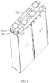
- this application further provides a battery pack 1000, including a connector 100, a cell module 200, and a housing assembly 300.
- the cell module 200 and the connector 100 are disposed inside the housing assembly 300.
- the connector 100 is connected to the cell module 200.
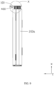
- the cell module 200 includes a plurality of battery cells 200a stacked along the third direction Z.
- Each battery cell 200a includes a cell housing 201, an electrode assembly (not shown in the drawing) disposed in the cell housing 201, and an electrode terminal 202 connected to the electrode assembly and led out of the cell housing 201.
- the electrode assembly includes a jelly-roll structure formed by winding a positive electrode plate, a negative electrode plate, and a separator.
- the third direction Z is perpendicular to the first direction X and the second direction Y.
- the cell housing 201 includes an aluminum laminated film.
- the battery cell 200a includes a pouch cell.
- a plurality of battery cells 200a are stacked along the third direction Z.
- the cell module 200 includes 6 battery cells 200a
- 3 of the battery cells 200a are stacked into a first group along the third direction Z
- the other 3 battery cells 200a are stacked into a second group along the third direction Z.
- the first group and the second group are arranged along the second direction Y.
- the cell housing 201 includes a first part 201a and a second part 201b.
- the first part 201a accommodates the electrode assembly, and the second part 201b is connected to the first part 201a.
- the electrode terminal 202 protrudes from the second part 201b.
- the plurality of battery cells 200a include a first battery cell 200a1.
- the first battery cell 200a1 is a battery cell located outermost along the third direction Z.
- a projection of the second connecting portion 32 is spaced apart from the projection of the cell housing 201, thereby alleviating the impairment caused by the second connecting portion 32 to the cell housing 201.
- the projection of the third connecting sub-portion 33a overlaps the projection of the cell housing 201, thereby enhancing the protection for the cell housing 201.
- the projection of the third connecting portion 33a is connected to the projection of the second connecting portion 32 and the projection of the cell housing 201, thereby further enhancing the protection for the cell housing 201.
- the first part 201a coordinates with the second part 201b to form a first recess 201c.
- a projection of the third connecting sub-portion 33a is at least partially located inside the first recess 201c, thereby utilizing the space of the first recess 201c and reducing the space occupied by the connector 100.
- the battery pack 1000 further includes a fourth insulator 400.
- the fourth insulator 400 is disposed in the first recess 201c and located between adjacent electrode terminals 202.
- the fourth insulator 400 disposed reduces the risk of a short circuit between adjacent electrode terminals 202, facilitates placement of the connector 100, and alleviates vibration of the connector 100.
- the fourth insulator 400 includes foam.
- the electrode terminal 202 includes a welding portion 202c.
- the welding portion 202c is formed by bending the electrode terminal 202, and is configured to be connected to the first connecting region 31a of the first connecting portion 31.
- the electrode terminals 202 of adjacent battery cells 200a are bent toward each other and connected to the first connecting region 31a.
- a projection of the welding portion 202c is located inside a projection of the first connecting region 31a.
- the positioning of the welding portion 202c makes it convenient to weld the welding portion 202c onto the first connecting region 31a and improves the yield rate of welding.
- the electrode terminal 202 includes a first terminal 202a and a second terminal 202b.
- the polarity of the first terminal 202a is opposite to the polarity of the second terminal 202b.
- the first terminal 202a and the second terminal 202b one is a positive terminal, and the other is a negative terminal.
- the first terminal 202a is a positive terminal
- the second terminal 202b is a negative terminal.
- the projection of the first terminal 202a of a battery cell 200a is spaced apart from the projection of the second terminal 202b of an adjacent battery cell 200a.
- the welding portion 202c of the first terminal 202a and the welding portion 202c of the second terminal 202b face each other and are spaced out, and are connected by the first connecting portion 31 to implement series connection between the battery cells 200a. Further, the welding portion 202c is connected to the first connecting portion 31 by welding such as laser welding, ultrasonic welding, and the like. In some other embodiments, the welding portion 202c may be connected to the first connecting portion 31 by other means such as conductive adhesive. Spacing out the electrode terminals 202 of the adjacent battery cells 200a reduces the impairment caused to the battery cell 200a during the welding.
- the first terminal 202a of the battery cell 200a may be spaced apart from the projection of the first terminal 202a of an adjacent battery cell 200a, and the two first terminals may be connected by the first connecting portion 31 to implement parallel connection between the battery cells 200a.
- the projection of the first terminal 202a of a battery cell 200a at least partially overlaps the projection of the second terminal 202b of an adjacent battery cell 200a.
- the first terminal 202a and the second terminal 202b are bent toward each other.
- the welding portion 202c of the first terminal 202a and the welding portion of the second terminal 202b are connected to each other by being stacked together.
- the welding portions 202c of the adjacent battery cells 200a are connected to each other. Therefore, to connect the welding portion 202c to the first connecting region 31a, only one welding operation needs to be performed, thereby reducing the processing operations.
- the projection of the first terminal 202a of the battery cell 200a may at least partially overlap the projection of the first terminal 202a of the adjacent battery cell 200a, and the two first terminals may be connected by the first connecting portion 31 to implement parallel connection between the battery cells 200a.
- the battery pack 1000 further includes a first structural component 500.
- the first structural component 500 includes an accommodation portion 501 configured to accommodate the battery cell 200a.
- the first structural component 500 includes a fourth opening 502 and a second recess 503 that communicate with each other.
- the fourth opening 502 extends along the second direction Y.
- the second recess 503 is recessed along a direction opposite to the first direction X.
- the second connecting portion 32 passes through the fourth opening 502
- the third connecting sub-portion 33a is partially disposed in the second recess 503, and the third connecting sub-portion 33a protrudes beyond the first structural component 500.
- the position of the third connecting portion 33 is defined by the second recess 503, thereby increasing the positioning precision during assembling, and facilitating assembling.
- the battery pack 1000 further includes a circuit board 600.
- the circuit board 600 may be a circuit board that includes a battery management system configured to intelligently manage and maintain each battery unit, reduce occurrences of overcharge and over discharge of the battery, prolong the lifespan of the battery, and monitor the status of the battery.
- the circuit board 600 includes a plurality of first connecting holes 601.
- the second connecting portion 32 is disposed in the first connection hole 601, and is fixed to the circuit board 600 by soldering, laser welding, or another welding method, so as to implement connection between the battery cell 200a and the circuit board 600.
- the first connecting hole 601 corresponds to the position of the second connecting portion 32.
- a part of the first connecting hole 601 extends along the second direction Y, and a part of the first connecting hole 601 extends along the first direction X.
- the distance between adjacent first connecting holes 601 is increased along the second direction Y, thereby reducing the risk of a short circuit between the second connecting portions 32 disposed in adjacent first connecting holes 601 during assembling, and increasing the creepage distance.
- the circuit board 600 includes a second connecting hole 602.
- the first structural component 500 includes a second bulge 504.
- the second bulge 504 is disposed in the second connecting hole 602, and is configured to mount the circuit board 600 to the first structural component 500.
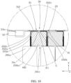
- the housing assembly 300 includes a first shell 301 and a second shell 302.
- the first shell 301 is connected to the second shell 302, so that the connector 100, the cell module 200, the first structural component 500, and the circuit board 600 are accommodated in the first shell 301 and the second shell 302.
- the first shell 301 includes a third bulge 301a.
- the third bulge 301 a is in fit with and connected to the second bulge 504 to implement connection between the first shell 301 and the first structural component 500.
- the third bulge 301a is disposed in the second bulge 504.
- Glue is provided in the clearance between the third bulge 301a and the second bulge 504, so as to fix the first shell 301 and the first structural component 500.
- the third bulge 301a includes a fifth opening 3011 through which the third bulge 301a can be filled with glue conveniently.
- this application further provides an electrical device 2000 that employs the battery pack 1000.
- the electrical device 2000 of this application may be, but is not limited to, a portable fax machine, portable photocopier, portable printer, video recorder, liquid crystal display television set, handheld cleaner, transceiver, backup power supply, electric vehicle, electric motorcycle, an electric power-assisted bicycle, electric tool, large household storage battery, or the like.
- a plurality of spaced conductive pieces 30 are disposed.
- Each conductive piece is connected to the electrode terminal 202 by the first connecting portion 31, and connected to the circuit board 600 by the second connecting portion 32, so as to implement connection between the battery cell 200a and the circuit board 600, and in turn, implement voltage collection, thereby avoiding the need of the current collecting plate, sampling terminal, and voltage sensing harness, reducing the number of materials that need to be used, and saving production cost.
- this application enables direct connection between the electrode terminal and the first connecting portion 31, thereby reducing the assembling difficulty.
Landscapes
- Chemical & Material Sciences (AREA)
- Chemical Kinetics & Catalysis (AREA)
- Electrochemistry (AREA)
- General Chemical & Material Sciences (AREA)
- Engineering & Computer Science (AREA)
- Microelectronics & Electronic Packaging (AREA)
- Manufacturing & Machinery (AREA)
- Connection Of Batteries Or Terminals (AREA)
- Battery Mounting, Suspending (AREA)
Applications Claiming Priority (2)
| Application Number | Priority Date | Filing Date | Title |
|---|---|---|---|
| CN202111145826.3A CN113782917B (zh) | 2021-09-28 | 2021-09-28 | 连接件、电池组及用电设备 |
| PCT/CN2022/114320 WO2023051104A1 (zh) | 2021-09-28 | 2022-08-23 | 连接件、电池组及用电设备 |
Publications (2)
| Publication Number | Publication Date |
|---|---|
| EP4407776A1 true EP4407776A1 (de) | 2024-07-31 |
| EP4407776A4 EP4407776A4 (de) | 2025-06-11 |
Family
ID=78854263
Family Applications (1)
| Application Number | Title | Priority Date | Filing Date |
|---|---|---|---|
| EP22874497.5A Pending EP4407776A4 (de) | 2021-09-28 | 2022-08-23 | Verbinder, batteriepack und elektrische vorrichtung |
Country Status (4)
| Country | Link |
|---|---|
| US (1) | US20240234960A1 (de) |
| EP (1) | EP4407776A4 (de) |
| CN (1) | CN113782917B (de) |
| WO (1) | WO2023051104A1 (de) |
Families Citing this family (7)
| Publication number | Priority date | Publication date | Assignee | Title |
|---|---|---|---|---|
| CN113782917B (zh) * | 2021-09-28 | 2026-01-16 | 宁德新能源科技有限公司 | 连接件、电池组及用电设备 |
| WO2023141819A1 (zh) * | 2022-01-26 | 2023-08-03 | 东莞新能安科技有限公司 | 一种电池组和用电设备 |
| JP2025531521A (ja) * | 2022-09-30 | 2025-09-19 | 厦門新能達科技有限公司 | 電池パックおよび電力消費機器 |
| CN118040240A (zh) * | 2022-11-08 | 2024-05-14 | 厦门新能达科技有限公司 | 电化学装置及用电设备 |
| CN116111296B (zh) * | 2023-03-24 | 2026-02-06 | 厦门新能达科技有限公司 | 电池模组以及用电设备 |
| CN119489763A (zh) * | 2023-08-17 | 2025-02-21 | 宁德时代新能源科技股份有限公司 | 配电装置、电池及用电设备 |
| WO2025241095A1 (zh) * | 2024-05-21 | 2025-11-27 | 宁德时代新能源科技股份有限公司 | 电池单体、电池、用电装置及储能装置 |
Family Cites Families (13)
| Publication number | Priority date | Publication date | Assignee | Title |
|---|---|---|---|---|
| CN102544616B (zh) * | 2010-12-08 | 2014-07-30 | 比亚迪股份有限公司 | 一种电池模组 |
| CN102623746A (zh) * | 2012-03-26 | 2012-08-01 | 宁德新能源科技有限公司 | 软包装锂离子电池 |
| CN107403969B (zh) * | 2016-05-20 | 2019-08-06 | 莫列斯有限公司 | 电池装置及电池连接模块 |
| DE102016223464A1 (de) * | 2016-11-25 | 2018-05-30 | Robert Bosch Gmbh | Verbindungsvorrichtung zur elektrischen Verbindung von elektrischen Speichereinheiten |
| CN112310520B (zh) * | 2019-10-21 | 2025-01-21 | 宁德时代新能源科技股份有限公司 | 连接组件、电池模块、电池组和电池单体作为电源的装置 |
| CN112310567B (zh) * | 2019-10-21 | 2022-03-18 | 宁德时代新能源科技股份有限公司 | 连接组件、电池模块、电池组以及使用电池模块作为电源的设备 |
| CN111435725A (zh) * | 2019-12-24 | 2020-07-21 | 蜂巢能源科技有限公司 | 动力电池、动力电池的汇流排组件及其加工方法 |
| CN113054330A (zh) * | 2019-12-26 | 2021-06-29 | 比亚迪股份有限公司 | 电池模组和具有其的动力电池包、电动汽车 |
| CN112310542B (zh) * | 2019-12-27 | 2022-01-11 | 宁德时代新能源科技股份有限公司 | 一种连接组件、电池模块、电池组、装置以及安装方法 |
| CN212366143U (zh) * | 2020-07-17 | 2021-01-15 | 东莞新能安科技有限公司 | 电芯模组及电池组 |
| CN214203832U (zh) * | 2021-02-08 | 2021-09-14 | 东莞新能安科技有限公司 | 电池组和用电装置 |
| CN216055068U (zh) * | 2021-09-28 | 2022-03-15 | 东莞新能安科技有限公司 | 连接件、电池组及用电设备 |
| CN113782917B (zh) * | 2021-09-28 | 2026-01-16 | 宁德新能源科技有限公司 | 连接件、电池组及用电设备 |
-
2021
- 2021-09-28 CN CN202111145826.3A patent/CN113782917B/zh active Active
-
2022
- 2022-08-23 EP EP22874497.5A patent/EP4407776A4/de active Pending
- 2022-08-23 WO PCT/CN2022/114320 patent/WO2023051104A1/zh not_active Ceased
-
2024
- 2024-03-27 US US18/617,791 patent/US20240234960A1/en active Pending
Also Published As
| Publication number | Publication date |
|---|---|
| US20240234960A1 (en) | 2024-07-11 |
| WO2023051104A1 (zh) | 2023-04-06 |
| CN113782917B (zh) | 2026-01-16 |
| EP4407776A4 (de) | 2025-06-11 |
| CN113782917A (zh) | 2021-12-10 |
Similar Documents
| Publication | Publication Date | Title |
|---|---|---|
| EP4407776A1 (de) | Verbinder, batteriepack und elektrische vorrichtung | |
| EP4207477A1 (de) | Elektrochemische vorrichtung und elektronische vorrichtung | |
| US11139539B2 (en) | Battery module having bus bar assembly | |
| US10916746B2 (en) | Secondary battery assembly including metallic body and battery cell | |
| EP1753050B1 (de) | Sekundärbatterie | |
| EP1714334B1 (de) | Sekundärbatterie mit struktur des zusammenbautyps | |
| EP4109617A2 (de) | Elektrochemische vorrichtung und elektronische vorrichtung | |
| US8785022B2 (en) | Secondary battery | |
| US8663827B2 (en) | Battery pack | |
| US9088032B2 (en) | Secondary battery | |
| US8697265B2 (en) | Protection circuit module for secondary battery and battery pack having the same | |
| CN104377339A (zh) | 可再充电电池组 | |
| JP2005285773A (ja) | 電極組立体とこれを備えた二次電池 | |
| CN100403592C (zh) | 二次电池 | |
| US20070037048A1 (en) | Secondary battery | |
| JP2000251868A (ja) | 薄型電池 | |
| US20070037045A1 (en) | Secondary battery | |
| EP4120461A1 (de) | Batteriezelle und elektronische vorrichtung | |
| CN216055068U (zh) | 连接件、电池组及用电设备 | |
| JP7546678B2 (ja) | 電池モジュール、それを含む電池パックおよびその製造方法 | |
| US20250174802A1 (en) | Battery pack and electric device | |
| CN215497001U (zh) | 电池组及用电设备 | |
| EP4095990A1 (de) | Batteriezelle, batteriepack und elektronische vorrichtung | |
| CN111952509A (zh) | 封装结构及电池模组 | |
| CN222507886U (zh) | 电池及用电设备 |
Legal Events
| Date | Code | Title | Description |
|---|---|---|---|
| STAA | Information on the status of an ep patent application or granted ep patent |
Free format text: STATUS: THE INTERNATIONAL PUBLICATION HAS BEEN MADE |
|
| PUAI | Public reference made under article 153(3) epc to a published international application that has entered the european phase |
Free format text: ORIGINAL CODE: 0009012 |
|
| STAA | Information on the status of an ep patent application or granted ep patent |
Free format text: STATUS: REQUEST FOR EXAMINATION WAS MADE |
|
| 17P | Request for examination filed |
Effective date: 20240426 |
|
| AK | Designated contracting states |
Kind code of ref document: A1 Designated state(s): AL AT BE BG CH CY CZ DE DK EE ES FI FR GB GR HR HU IE IS IT LI LT LU LV MC MK MT NL NO PL PT RO RS SE SI SK SM TR |
|
| DAV | Request for validation of the european patent (deleted) | ||
| DAX | Request for extension of the european patent (deleted) | ||
| A4 | Supplementary search report drawn up and despatched |
Effective date: 20250512 |
|
| RIC1 | Information provided on ipc code assigned before grant |
Ipc: H01M 50/59 20210101ALI20250506BHEP Ipc: H01M 50/588 20210101ALI20250506BHEP Ipc: H01M 50/557 20210101ALI20250506BHEP Ipc: H01M 50/516 20210101ALI20250506BHEP Ipc: H01M 50/284 20210101ALI20250506BHEP Ipc: H01M 50/211 20210101ALI20250506BHEP Ipc: H01M 50/178 20210101ALI20250506BHEP Ipc: H01M 50/105 20210101ALI20250506BHEP Ipc: H01M 10/42 20060101ALI20250506BHEP Ipc: H01M 50/543 20210101ALI20250506BHEP Ipc: H01M 50/503 20210101ALI20250506BHEP Ipc: H01M 50/50 20210101AFI20250506BHEP |
|
| RAP1 | Party data changed (applicant data changed or rights of an application transferred) |
Owner name: NINGDE AMPEREX TECHNOLOGY LIMITED |
|
| RAP3 | Party data changed (applicant data changed or rights of an application transferred) |
Owner name: NINGDE AMPEREX TECHNOLOGY LIMITED |