EP4407367A1 - Procédé et système de stabilisation d'un faisceau laser pour une source de photons enchevêtrée - Google Patents
Procédé et système de stabilisation d'un faisceau laser pour une source de photons enchevêtrée Download PDFInfo
- Publication number
- EP4407367A1 EP4407367A1 EP23153468.6A EP23153468A EP4407367A1 EP 4407367 A1 EP4407367 A1 EP 4407367A1 EP 23153468 A EP23153468 A EP 23153468A EP 4407367 A1 EP4407367 A1 EP 4407367A1
- Authority
- EP
- European Patent Office
- Prior art keywords
- pump
- source
- pump beam
- polarization
- adjustment
- Prior art date
- Legal status (The legal status is an assumption and is not a legal conclusion. Google has not performed a legal analysis and makes no representation as to the accuracy of the status listed.)
- Granted
Links
Images


Classifications
-
- G—PHYSICS
- G02—OPTICS
- G02F—OPTICAL DEVICES OR ARRANGEMENTS FOR THE CONTROL OF LIGHT BY MODIFICATION OF THE OPTICAL PROPERTIES OF THE MEDIA OF THE ELEMENTS INVOLVED THEREIN; NON-LINEAR OPTICS; FREQUENCY-CHANGING OF LIGHT; OPTICAL LOGIC ELEMENTS; OPTICAL ANALOGUE/DIGITAL CONVERTERS
- G02F1/00—Devices or arrangements for the control of the intensity, colour, phase, polarisation or direction of light arriving from an independent light source, e.g. switching, gating or modulating; Non-linear optics
- G02F1/01—Devices or arrangements for the control of the intensity, colour, phase, polarisation or direction of light arriving from an independent light source, e.g. switching, gating or modulating; Non-linear optics for the control of the intensity, phase, polarisation or colour
- G02F1/0121—Operation of devices; Circuit arrangements, not otherwise provided for in this subclass
- G02F1/0123—Circuits for the control or stabilisation of the bias voltage, e.g. automatic bias control [ABC] feedback loops
-
- G—PHYSICS
- G02—OPTICS
- G02F—OPTICAL DEVICES OR ARRANGEMENTS FOR THE CONTROL OF LIGHT BY MODIFICATION OF THE OPTICAL PROPERTIES OF THE MEDIA OF THE ELEMENTS INVOLVED THEREIN; NON-LINEAR OPTICS; FREQUENCY-CHANGING OF LIGHT; OPTICAL LOGIC ELEMENTS; OPTICAL ANALOGUE/DIGITAL CONVERTERS
- G02F1/00—Devices or arrangements for the control of the intensity, colour, phase, polarisation or direction of light arriving from an independent light source, e.g. switching, gating or modulating; Non-linear optics
- G02F1/01—Devices or arrangements for the control of the intensity, colour, phase, polarisation or direction of light arriving from an independent light source, e.g. switching, gating or modulating; Non-linear optics for the control of the intensity, phase, polarisation or colour
- G02F1/09—Devices or arrangements for the control of the intensity, colour, phase, polarisation or direction of light arriving from an independent light source, e.g. switching, gating or modulating; Non-linear optics for the control of the intensity, phase, polarisation or colour based on magneto-optical elements, e.g. exhibiting Faraday effect
- G02F1/093—Devices or arrangements for the control of the intensity, colour, phase, polarisation or direction of light arriving from an independent light source, e.g. switching, gating or modulating; Non-linear optics for the control of the intensity, phase, polarisation or colour based on magneto-optical elements, e.g. exhibiting Faraday effect used as non-reciprocal devices, e.g. optical isolators, circulators
-
- G—PHYSICS
- G02—OPTICS
- G02F—OPTICAL DEVICES OR ARRANGEMENTS FOR THE CONTROL OF LIGHT BY MODIFICATION OF THE OPTICAL PROPERTIES OF THE MEDIA OF THE ELEMENTS INVOLVED THEREIN; NON-LINEAR OPTICS; FREQUENCY-CHANGING OF LIGHT; OPTICAL LOGIC ELEMENTS; OPTICAL ANALOGUE/DIGITAL CONVERTERS
- G02F1/00—Devices or arrangements for the control of the intensity, colour, phase, polarisation or direction of light arriving from an independent light source, e.g. switching, gating or modulating; Non-linear optics
- G02F1/35—Non-linear optics
- G02F1/3515—All-optical modulation, gating, switching, e.g. control of a light beam by another light beam
- G02F1/3517—All-optical modulation, gating, switching, e.g. control of a light beam by another light beam using an interferometer
- G02F1/3519—All-optical modulation, gating, switching, e.g. control of a light beam by another light beam using an interferometer of Sagnac type, i.e. nonlinear optical loop mirror [NOLM]
-
- G—PHYSICS
- G02—OPTICS
- G02F—OPTICAL DEVICES OR ARRANGEMENTS FOR THE CONTROL OF LIGHT BY MODIFICATION OF THE OPTICAL PROPERTIES OF THE MEDIA OF THE ELEMENTS INVOLVED THEREIN; NON-LINEAR OPTICS; FREQUENCY-CHANGING OF LIGHT; OPTICAL LOGIC ELEMENTS; OPTICAL ANALOGUE/DIGITAL CONVERTERS
- G02F1/00—Devices or arrangements for the control of the intensity, colour, phase, polarisation or direction of light arriving from an independent light source, e.g. switching, gating or modulating; Non-linear optics
- G02F1/35—Non-linear optics
- G02F1/3526—Non-linear optics using two-photon emission or absorption processes
-
- G—PHYSICS
- G02—OPTICS
- G02F—OPTICAL DEVICES OR ARRANGEMENTS FOR THE CONTROL OF LIGHT BY MODIFICATION OF THE OPTICAL PROPERTIES OF THE MEDIA OF THE ELEMENTS INVOLVED THEREIN; NON-LINEAR OPTICS; FREQUENCY-CHANGING OF LIGHT; OPTICAL LOGIC ELEMENTS; OPTICAL ANALOGUE/DIGITAL CONVERTERS
- G02F1/00—Devices or arrangements for the control of the intensity, colour, phase, polarisation or direction of light arriving from an independent light source, e.g. switching, gating or modulating; Non-linear optics
- G02F1/35—Non-linear optics
- G02F1/39—Non-linear optics for parametric generation or amplification of light, infrared or ultraviolet waves
-
- G—PHYSICS
- G02—OPTICS
- G02B—OPTICAL ELEMENTS, SYSTEMS OR APPARATUS
- G02B27/00—Optical systems or apparatus not provided for by any of the groups G02B1/00 - G02B26/00, G02B30/00
- G02B27/09—Beam shaping, e.g. changing the cross-sectional area, not otherwise provided for
- G02B27/0905—Dividing and/or superposing multiple light beams
Definitions
- the present invention provides a method for stabilization of a pump beam for an entangled photon source according to the preamble of claim 1 and a system for stabilization of a pump beam for an entangled photon source according to the preamble of claim 13.
- SPDC spontaneous parametric down-conversion
- the non-linear crystal is pumped by a pump laser. While there are many different possibilities to fabricate and align such crystals, they all have in common that they require a pump laser with well-defined properties, such as operating mode (continuous wave or pulsed), polarization, power and wavelength.
- Known stabilization schemes for lasers aim for the stabilization of the wavelength, which is vital for interferometric applications but is not directed at a constant generation rate and quality of entangled photon pairs.
- a method of stabilization of a pump laser in an entangled photon source is provided according to claim 1.
- This object is achieved by a method of stabilization of a pump beam for an entangled photon source, and preferably for stabilization of the pump beam for the generation of entangled photons, with the steps
- the method comprises the steps
- a system of stabilization of a pump laser in an entangled photon source is provided according to claim 13.
- a system for stabilization of a pump beam in an entangled photon source comprising a pump laser generating a polarized pump beam and a source, whereby the source is arranged behind the pump laser and comprises a non-linear element for the generation of entangled photons.
- the system comprises a polarizing monitoring means arranged between the pump laser and the source or behind the source, whereby
- An advantage of the inventive method and inventive system is the automated stabilization of the power and/or the polarization of the pump laser leading to a stable generation of entangled photons with constant quality properties. This is realized by monitoring the pump beam after the generation of entangled photons. After the generation of the entangled photons means, that the pump beam is first used to pump the non-linear element for the generation of the entangled photons and in a second step the pump beam is split up into the two part-pump beams. The splitting up can be realized behind the source by a transmitted pump beam through the source or between the source and the pump laser by a in the source reflected or guided pump beam.
- the inventive method and the inventive system it is not necessary to measure the generated entangled photons to check and stabilize the source and the properties of the entangled photons, but by monitoring the pump beam after the entangled photon generation. This eliminates the need to interrupt the entangled photon generation and key generation by quantum key distribution (QKD) for maintenance and adjustment purposes.
- QKD quantum key distribution
- the power as well as the polarization is a crucial property of the pump beam which influences both the number of generated entangled photons and the state of the entangled photons.
- control signal is an electrical signal, preferably whose magnitude is proportional to the measured sum and/or ratio of the two part-pump beams.
- the steps i) to v) form a control at or during the generation of the entangled photons by pumping the non-linear element by the pump beam.
- control comprises
- control means in step iv) compares the actual value of the sum of the two part-pump beams and/or the ratio of the two part-pump beams with a setpoint sum value and/or a setpoint ratio value and the control means determines and generates the control signal on the basis of the comparison.
- the setpoint sum value and/or the setpoint ratio value are set manually or are set by properties defined by a first adjustment of the entangled photon source.
- control loop is permanently active.
- the advantage of the invention is that the control loop can be permanently active while generating entangled photons. An interruption of the generation of the entangled photons for adjustment or maintenance is not necessary.
- control loop can be deactivated at least temporarily or periodically.
- control loop can be switched on again periodically for a certain time.
- control means is formed as a digital controller or as an analog circuit.
- the two detection means generate a detection signal each in step iii).
- each detection signal is dependent or proportional to the intensity of one out of the two part-pump beams each.
- the control signal is generated by the sum or the ratio of the two detection signals of the two detection means.
- the control signal is generated based on the detection signals of the two part-pump beams from the detection means. For example, the intensity of the two part-pump beams is detected, whereby the detection signal in the detection means is proportional to the intensity of the two part-pump beams, leading to a detection signal proportional to the intensity of the two part-pump beams.
- the detection means is a power meter, and/or a polarimeter, and/or a photodiode, and/or a thermal sensor.
- the pump beam is split up in the polarizing monitoring means after a transmission of the pump beam through the source.
- the polarizing monitoring means is arranged behind the source.
- the pump beam is split up in the polarizing monitoring means after a reflection of the pump beam in the source or a guidance back of the pump beam in the source towards the pump laser.
- the polarizing monitoring means is arranged between the pump laser and the source.
- the pump beam is guided in the source back to the pump laser, preferably on the same spatial mode out of the source.
- This can be realized by a reflection or guidance of the pump beam in the source or a loop configuration for the pump beam in the source, preferably a Sagnac-loop configuration.
- the polarizing monitoring means comprises one or more polarizing beam splitter, and/or one or more isolator.
- the polarization rotation elements can be arranged between the multiple elements of the polarizing monitoring means in order to enable two orthogonal output ports.
- the two orthogonal polarizations of the two part-pump beams can be the horizontal linear polarization and the vertical linear polarization, or the 45° linear polarization and the -45° linear polarization.
- the actuation means is the part of the control loop which possesses the physical variable to be controlled and on which the control means act, preferably in step v), via the control signal.
- the actuation means of the inventive method and system is the pump laser and/or the polarization adjustment means arranged between the pump laser and the source.
- the physical variable may be the electrical power for the pump laser, or the temperature, or a position of a grating in the pump laser, or a position and/or angle setting of a fiber coupler, or a polarization setting position of the polarization adjustment means or an electrical power of the polarization adjustment means, for example for liquid crystals or motorized wave plates.
- control signal of the ratio of the two part-pump beams is used for the adjustment of the polarization of the pump beam.
- the adjustment of the polarization of the pump beam is realized by the control of the pump laser.
- the electrical power for the pump laser, or the temperature, or a position of a grating in the pump laser is controlled in order to adjust the polarization of the pump beam.
- the adjustment of the polarization of the pump beam is realized by the control of one or more polarization adjustment means arranged between the pump laser and the source.
- the polarization rotation by the polarization adjustment means is controlled in order to adjust the polarization of the pump beam.
- the polarization adjustment means is arranged in front of the source. Preferably there is no additional polarization changing optical element arranged between the polarization adjustment means and the source.
- control signal of the sum of the two part-pump beams is used for the adjustment of the power of the pump beam.
- the adjustment of the power of the pump beam is realized by the control of the pump laser.
- the electrical power for the pump laser, or the temperature, or a position of a grating in the pump laser is controlled in order to adjust the power of the pump beam.
- the adjustment of the power of the pump beam is realized by the control of the polarization adjustment means arranged between the pump laser and the source.
- the polarization adjustment means is arranged in front of a polarizing element. By changing the polarization of the pump beam in front of the polarizing element the power of the transmitted pump beam through the polarizing element is adjusted.
- the adjustment of the power of the pump beam is realized by the control of multiple polarization adjustment means arranged between the pump laser and the source.
- at least a first polarization adjustment means is arranged in front of a first polarizing element and at least a second polarization adjustment means is arranged behind the first polarizing element and in front of a second polarizing element.
- the advantage of this embodiment is that output modes of the first and second polarizing element can be used at the same time as the monitoring means arranged between the source and the pump laser.
- the polarizing element is a polarizing beam splitter, and/or a polarizer, and/or an isolator.
- the polarization adjustment means is one or more motorized wave plates, and/or one or more motorized fiber paddles, and/or one or more motorized fiber squeezers, and/or one or more liquid crystals.
- the adjustment of the power and of the polarization of the pump beam is realized by control of multiple polarization adjustment means arranged between the pump laser and the source.
- at least a first polarization adjustment means is arranged between the pump laser and a polarizing element and at least a second polarization adjustment means is arranged behind the polarizing element.
- the pump laser is a continuous wave laser generating a continuous wave pump laser beam or a pulsed laser generating a pulsed pump laser beam.
- the source is formed as a continuous wave entangled photon source or a pulsed entangled photon source.
- the source is a Sagnac-type entangled photon source, or an entangled photon source with crossed crystals inside a Sagnac loop, or an entangled photon source using a crystal double-pass inside a Sagnac interferometer, or a crossed crystal type entangled photon source, or an entangled photon source with one non-linear element pumped in two directions, or a BBO-type entangled photon source, or a BiBO-type entangled photon source, or a beam-displacer entangled photon source, or a parallel-crystal entangled photon source, or a folded-Mach-Zehnder type entangled photon source, or an entangled photon source based on a linear displacement interferometer, or an entangled photon source using interferometers on each entangled photon individually after creation, or a rail-cross entangled photon source, or a single-crystal single-pass entangled photon source with walk-off
- the transmission of the laser beam can be realized via a free-space channel and/or a fiber channel.
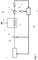
- Fig. 1 shows a first embodiment of the inventive system for the stabilization of a pump beam 10 for the generation of entangled photons 20 comprising a pump laser 1 and a source 2.
- the pump laser 1 generates the pump beam 10 which is guided to the source 2.
- the source 2 comprises a non-linear element 9 which is pumped by the pump beam 10 in order to generate the entangled photons 20.
- the system comprises in addition a polarizing monitoring means, arranged in the embodiment of Fig. 1 behind the source 2.
- the pump beam 10 is in this embodiment transmitted through the source for the generation of the entangled photons 20 and then split by the polarizing monitoring means 3 into two part-pump beams 11.
- the polarizing monitoring means 3 is in the embodiment of Fig. 1 a polarizing beam splitter 7 in order to split the two part-pump beams 11 into two beams with orthogonal polarization.
- two detection means 4 are arranged in order to detect the two part-pump beams 11.
- the two detection means 4 are power meters detecting the intensity of the two part-pump beams 11 generating two detection signals proportional to the intensity of the two part-pump beams 11.
- the inventive system of Fig. 1 also comprises a control means 5, which receives the detection signals of the two detection means 4.
- a control signal is generated by the sum or the ratio of the two detection signals.
- the control signal 50 is proportional to the sum or the ratio of the two part-pump beams 11.
- the control signal 50 is sent to the pump laser 1 and/or to a polarization adjustment means 6.
- a control loop is formed by the pump laser 1 and/or a polarization adjustment means 6 as actuation means, the spatial mode filter means 3, the detection means 4 and the control means 5.
- the polarization adjustment means 6 is a motorized wave plate or a liquid crystal and is arranged between the pump laser 1 and the source 2 in the beam path of the pump beam 10.
- the motorized wave plate or a liquid crystal are formed to introduce a controlled polarization rotation of the pump beam 10.
- the adjustment of the polarization of the pump beam 10 is realized by the control of the one or more wave plates and/or one or more liquid crystals as polarization adjustment means 6 arranged between the pump laser 1 and the source 2 by the control signal 50.
- the control signal 50 generated by the ratio of the two part-pump beams 11 is used.
- the control signal 50 controls the polarization rotation by the wave plate or the liquid crystal in order to adjust the polarization of the pump beam 10.
- control signal 50 generated by the sum of the two part-pump beams 11 is used for the adjustment of the power of the pump beam 10.
- the adjustment of the power of the pump beam 10 is realized by the control of the pump laser 1 by the control signal 50.
- the transmitted part-pump beam 11 has to be maximized while the reflected part-pump beam 11 has to be minimized.
- the sum of both part-pump beams 11 has to be kept stable.
- Fig. 2 shows another embodiment of the inventive system of Fig. 1 , whereby Fig. 2 differs from Fig. 1 only in that between the pump laser 1 and the polarizing adjustment means 6 from Fig. 1 in front of the source in addition a polarizing beam splitter 7 as a polarizing means is arranged and a second adjustment means 6 between the pump laser 1 and the polarizing beam splitter 7 is arranged.
- the second adjustment means 6 is in the example of Fig. 2 one or more wave plates and/or one or more liquid crystals.
- the pump laser 1 and the first polarization adjustment means 6 in front of the source 2 in Fig. 2 can be used for the adjustment of the polarization and/or the power of the pump beam 10 as described in Fig. 1 .
- the second adjustment means 6 in Fig. 2 between the pump laser 1 and the polarizing beam splitter 7 can be used in addition for the adjustment of the power of the pump beam 10.
- the pump laser 1 generates the polarized pump beam 10. Only the horizontal linear polarization part of the pump beam 10 is transmitted through the polarizing beam splitter 7 in Fig. 2 .
- the polarization of the pump beam 10 in front of the polarizing beam splitter 7 can be changed in order to increase or decrease the transmitted part or intensity of the pump beam 10 through the polarizing beam splitter 7, thus controlling the power of the pump beam 10 for the generation of the entangled photons 20.
- the second adjustment means 6 together with the polarizing beam splitter 7 can be controlled for the stabilization of the power of the pump beam 10. If this is not sufficient, in addition the pump laser 1 can be controlled for the stabilization of the power of the pump beam 10.
- the first adjustment means 6 in front of the source 2 can be controlled for the stabilization of the polarization of the pump beam 10.
- Fig. 3 shows another embodiment of the inventive system for the stabilization of a pump beam, comprising the pump laser 1, the source 2 and the polarizing monitoring means 3, whereby the polarizing monitoring means 3 is arranged in this embodiment between the pump laser 1 and the source 2 in the beam path of the pump beam 10.
- the pump beam 10 is monitored after the generation of the entangled photons 20 by a reflection or guidance of the beam path 10 in the source 2 back to the pump laser 1.
- This embodiment can be used for sources 2 guiding the pump beam 10 back towards the pump laser 1, as for example a Sagnac type entangled photon source 2 or a two-direction pumped crystal source.
- the polarizing monitoring means 3 is formed as an isolator 12.
- the advantage of the polarizing monitoring means 3 formed as isolator 12 is that the isolator 12 is used for cleaning the polarization of the pump beam 10 by the transmission of the pump beam 10 from the pump laser 1 to the source 2 and in addition it is used in the embodiment of Fig. 3 as polarizing monitoring means 3 with two outputs after the generation of the entangled photons 20.
- the two detection means 4 are arranged behind the two outputs of the isolator 12 for the pump beam 10 traveling from the source 2 to the pump laser 1.
- the isolator 12 splits the reflected pump beam 10 into two orthogonal part-pump beams 11. As in the embodiment of Fig. 1 the two part-pump beams 11 are detected by the two detection means 4 and used for the generation of the control signal 50.
- the embodiment of Fig. 3 comprises two polarization adjustment means 6, the first polarization adjustment means 6 in front of the source 2 and the second polarization adjustment means 6 between the pump laser 1 and the isolator 12.
- the first polarization adjustment means 6 in front of the source 2 in Fig. 3 can be used for the adjustment of the polarization as described for Fig. 1 or 2 .
- the pump laser 1 can be used for the adjustment of the power as described for Fig. 1 or 2 .
- the second adjustment means 6 between the pump laser 1 and the isolator 12 in Fig. 3 can be used for the adjustment of the power of the pump beam 10 as described in Fig. 2 .
- the isolator 12 is used instead of the polarizing beam splitter 7.
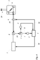
- Fig. 4 shows another embodiment of the inventive system whereby Fig. 4 differs from Fig. 1 only in that the polarizing monitoring means 3 is arranged in the embodiment of Fig. 4 branching off from the pump beam 10 between the source 2 and the pump laser 1, and the pump beam 10 is reflected or guided back inside the source 2 towards the pump laser 1 as explained for Fig. 3 .
- the non-linear element 9 is arranged in Fig. 4 in a Sagnac type source 2.
- a beam splitter 8 is arranged between the pump laser 1 and the first polarization adjustment means 6 in front of the source 2.
- the beam splitter 8 a part of the pump beam 10 is reflected and guided to the polarizing monitoring means 3 which is formed in the example of Fig. 4 as polarizing beam splitter 7.
- control signal 50 and the stabilization of the power and/or the polarization of the pump beam 10 can be realized in the embodiment of Fig. 4 as described for the embodiment of Fig. 1 .
- Fig. 5 shows another embodiment of the inventive system whereby Fig. 5 differs from Fig. 3 only in that between the first polarization adjustment means 6 in front of the source 2 and the isolator 12 a first part of the polarizing monitoring means 3 and a third polarization adjustment means 6 is arranged.
- the polarizing monitoring means 3 comprises a first part formed as polarizing beam splitter 7 and a second part formed as isolator 12. Important is that the output of the isolator 12 is an orthogonal polarization to the output of the polarizing beam splitter 7.
- the first polarization adjustment means 6 in front of the source 2 in Fig. 5 can be used for the adjustment of the polarization as described in Fig. 1 to 4 .
- the pump laser 1 in Fig. 5 can be used for the adjustment of the power as described in Fig. 1 to 4 .
- the second adjustment means 6 between the pump laser 1 and the isolator 12 in Fig. 5 can be used for the adjustment of the power of the pump beam 10 as described in Fig. 2 and 3 .
- the isolator 12 is used instead of the polarizing beam splitter 7.
- the third adjustment means 6 formed as one or more wave plates and/or one or more liquid crystals between the isolator 12 and the polarizing beam splitter 7 can be used in addition for the adjustment of the power of the pump beam 10 as described in Fig. 2 and 3 for the second adjustment means 6.
- This third adjustment means 6 is an optional adjustment means 6.
- the second adjustment means 6 is sufficient.
Landscapes
- Physics & Mathematics (AREA)
- Nonlinear Science (AREA)
- General Physics & Mathematics (AREA)
- Optics & Photonics (AREA)
- Engineering & Computer Science (AREA)
- Power Engineering (AREA)
- Lasers (AREA)
Priority Applications (2)
| Application Number | Priority Date | Filing Date | Title |
|---|---|---|---|
| EP23153468.6A EP4407367B1 (fr) | 2023-01-26 | 2023-01-26 | Procédé et système de stabilisation d'un faisceau laser pour une source de photons enchevêtrée |
| PCT/EP2024/051874 WO2024156853A1 (fr) | 2023-01-26 | 2024-01-26 | Procédé et système de stabilisation d'un faisceau laser pour une source de photons enchevêtrés |
Applications Claiming Priority (1)
| Application Number | Priority Date | Filing Date | Title |
|---|---|---|---|
| EP23153468.6A EP4407367B1 (fr) | 2023-01-26 | 2023-01-26 | Procédé et système de stabilisation d'un faisceau laser pour une source de photons enchevêtrée |
Publications (3)
| Publication Number | Publication Date |
|---|---|
| EP4407367A1 true EP4407367A1 (fr) | 2024-07-31 |
| EP4407367B1 EP4407367B1 (fr) | 2025-12-03 |
| EP4407367C0 EP4407367C0 (fr) | 2025-12-03 |
Family
ID=85122589
Family Applications (1)
| Application Number | Title | Priority Date | Filing Date |
|---|---|---|---|
| EP23153468.6A Active EP4407367B1 (fr) | 2023-01-26 | 2023-01-26 | Procédé et système de stabilisation d'un faisceau laser pour une source de photons enchevêtrée |
Country Status (2)
| Country | Link |
|---|---|
| EP (1) | EP4407367B1 (fr) |
| WO (1) | WO2024156853A1 (fr) |
Citations (6)
| Publication number | Priority date | Publication date | Assignee | Title |
|---|---|---|---|---|
| US20100141857A1 (en) * | 2007-06-15 | 2010-06-10 | National Institute Of Information And Communications Technology | Optical waveform shaping device |
| CN105391547A (zh) * | 2015-10-16 | 2016-03-09 | 华南师范大学 | 一种m-z型轨道角动量纠缠密钥分发方法与网络系统 |
| CN108984153A (zh) * | 2018-08-27 | 2018-12-11 | 中国科学技术大学 | 一种设备无关量子随机数产生器系统及方法 |
| WO2020143927A1 (fr) * | 2019-01-09 | 2020-07-16 | Österreichische Akademie der Wissenschaften | Source pour paires de photons enchevêtrés à haute dimension |
| EP3754396A1 (fr) * | 2019-06-17 | 2020-12-23 | Österreichische Akademie der Wissenschaften | Alignement d'une source de photons enchevêtrée |
| US11343001B2 (en) * | 2018-12-05 | 2022-05-24 | Nederlandse Organisatie Voor Toegepast-Natuurwetenschappelijk Onderzoek Tno | Photon exchange based quantum network and method of operating such a network |
Family Cites Families (3)
| Publication number | Priority date | Publication date | Assignee | Title |
|---|---|---|---|---|
| US5136600A (en) * | 1990-09-18 | 1992-08-04 | Litton Systems Inc. | Stabilization apparatus and method for an sfs |
| JP7103942B2 (ja) * | 2015-10-05 | 2022-07-20 | キュービテック,インコーポレイテッド | バイフォトンの調整可能な光源 |
| WO2022165134A1 (fr) * | 2021-01-29 | 2022-08-04 | Qunnect, Inc. | Systèmes et procédés pour réaliser des télécommunications quantiques à l'aide d'une source d'intrication bichromatique |
-
2023
- 2023-01-26 EP EP23153468.6A patent/EP4407367B1/fr active Active
-
2024
- 2024-01-26 WO PCT/EP2024/051874 patent/WO2024156853A1/fr not_active Ceased
Patent Citations (6)
| Publication number | Priority date | Publication date | Assignee | Title |
|---|---|---|---|---|
| US20100141857A1 (en) * | 2007-06-15 | 2010-06-10 | National Institute Of Information And Communications Technology | Optical waveform shaping device |
| CN105391547A (zh) * | 2015-10-16 | 2016-03-09 | 华南师范大学 | 一种m-z型轨道角动量纠缠密钥分发方法与网络系统 |
| CN108984153A (zh) * | 2018-08-27 | 2018-12-11 | 中国科学技术大学 | 一种设备无关量子随机数产生器系统及方法 |
| US11343001B2 (en) * | 2018-12-05 | 2022-05-24 | Nederlandse Organisatie Voor Toegepast-Natuurwetenschappelijk Onderzoek Tno | Photon exchange based quantum network and method of operating such a network |
| WO2020143927A1 (fr) * | 2019-01-09 | 2020-07-16 | Österreichische Akademie der Wissenschaften | Source pour paires de photons enchevêtrés à haute dimension |
| EP3754396A1 (fr) * | 2019-06-17 | 2020-12-23 | Österreichische Akademie der Wissenschaften | Alignement d'une source de photons enchevêtrée |
Non-Patent Citations (2)
| Title |
|---|
| NATALIA HERRERA VALENCIA ET AL: "Unscrambling Entanglement through a Complex Medium", ARXIV.ORG, CORNELL UNIVERSITY LIBRARY, 201 OLIN LIBRARY CORNELL UNIVERSITY ITHACA, NY 14853, 10 October 2019 (2019-10-10), XP081513486 * |
| SEBASTIAN ECKER ET AL: "Overcoming Noise in Entanglement Distribution", ARXIV.ORG, CORNELL UNIVERSITY LIBRARY, 201 OLIN LIBRARY CORNELL UNIVERSITY ITHACA, NY 14853, 2 April 2019 (2019-04-02), XP081543628, DOI: 10.1103/PHYSREVX.9.041042 * |
Also Published As
| Publication number | Publication date |
|---|---|
| EP4407367B1 (fr) | 2025-12-03 |
| EP4407367C0 (fr) | 2025-12-03 |
| WO2024156853A1 (fr) | 2024-08-02 |
Similar Documents
| Publication | Publication Date | Title |
|---|---|---|
| US8385548B2 (en) | System and method for entangled photons generation and measurement | |
| US20100208334A1 (en) | System and method for entangled photons generation and measurement | |
| US8265280B2 (en) | System and method of entangled photons generation | |
| US6614584B1 (en) | Laser frequency converter with automatic phase matching adjustment | |
| CN111697422B (zh) | 一种相位调制型拉曼光功率控制方法及其系统 | |
| Willke et al. | Stabilized lasers for advanced gravitational wave detectors | |
| US9362714B1 (en) | Architecture for all-fiber delivery of coherently combined laser power | |
| CN117278215A (zh) | 用于量子密钥分发和光通信的光量子芯片及相位补偿方法 | |
| US7248609B2 (en) | Amplified beam source | |
| US12368276B2 (en) | Sequential-pulse single-frequency laser power amplification apparatus and sequence controllable multi-laser system | |
| GB2535495A (en) | Dither free bias control | |
| WO2021086712A1 (fr) | Multiplexage de formes d'onde amplifiées par fibre | |
| IL290465A (en) | A Magnetometer System and Method | |
| Sulaiman et al. | Investigation on factors influencing flatness of a bidirectional SOA-based multiwavelength fiber laser | |
| US20240333394A1 (en) | High precision photonic readout and performing high precision photon sensing | |
| EP4407367A1 (fr) | Procédé et système de stabilisation d'un faisceau laser pour une source de photons enchevêtrée | |
| EP3754396A1 (fr) | Alignement d'une source de photons enchevêtrée | |
| US7518711B2 (en) | Optical waveform measurement apparatus and optical waveform measurement method | |
| Legre et al. | Implementation of continuous variable quantum cryptography in optical fibres using a go-&-return configuration | |
| JP3933965B2 (ja) | 波長特性可変装置、光増幅器および光伝送システム | |
| JP3266165B2 (ja) | 光ファイバ増幅器 | |
| CN118300778A (zh) | 一种基于纠缠量子密钥分发的偏振补偿系统和方法 | |
| JP2019184599A (ja) | 光ファイバジャイロ光源のための対称波長マルチプレクサ | |
| EP4407371B1 (fr) | Procédé et système d'alignement d'une source de photons enchevêtrée | |
| Ma et al. | Servo Control of High Degree of Linear Polarization Output from Polarization-Maintaining Fiber and its Application in Fiber-Component Based Frequency Modulation Spectroscopy |
Legal Events
| Date | Code | Title | Description |
|---|---|---|---|
| PUAI | Public reference made under article 153(3) epc to a published international application that has entered the european phase |
Free format text: ORIGINAL CODE: 0009012 |
|
| STAA | Information on the status of an ep patent application or granted ep patent |
Free format text: STATUS: THE APPLICATION HAS BEEN PUBLISHED |
|
| AK | Designated contracting states |
Kind code of ref document: A1 Designated state(s): AL AT BE BG CH CY CZ DE DK EE ES FI FR GB GR HR HU IE IS IT LI LT LU LV MC ME MK MT NL NO PL PT RO RS SE SI SK SM TR |
|
| STAA | Information on the status of an ep patent application or granted ep patent |
Free format text: STATUS: REQUEST FOR EXAMINATION WAS MADE |
|
| 17P | Request for examination filed |
Effective date: 20240821 |
|
| RBV | Designated contracting states (corrected) |
Designated state(s): AL AT BE BG CH CY CZ DE DK EE ES FI FR GB GR HR HU IE IS IT LI LT LU LV MC ME MK MT NL NO PL PT RO RS SE SI SK SM TR |
|
| STAA | Information on the status of an ep patent application or granted ep patent |
Free format text: STATUS: EXAMINATION IS IN PROGRESS |
|
| 17Q | First examination report despatched |
Effective date: 20241028 |
|
| REG | Reference to a national code |
Ref country code: DE Ref legal event code: R079 Free format text: PREVIOUS MAIN CLASS: G02F0001010000 Ipc: G02F0001390000 Ref country code: DE Ref legal event code: R079 Ref document number: 602023009115 Country of ref document: DE Free format text: PREVIOUS MAIN CLASS: G02F0001010000 Ipc: G02F0001390000 |
|
| RAP1 | Party data changed (applicant data changed or rights of an application transferred) |
Owner name: QUANTUM TECHNOLOGY LABORATORIES GMBH |
|
| RAP1 | Party data changed (applicant data changed or rights of an application transferred) |
Owner name: QUANTUM INDUSTRIES GMBH Owner name: QUANTUM TECHNOLOGY LABORATORIES GMBH |
|
| GRAP | Despatch of communication of intention to grant a patent |
Free format text: ORIGINAL CODE: EPIDOSNIGR1 |
|
| STAA | Information on the status of an ep patent application or granted ep patent |
Free format text: STATUS: GRANT OF PATENT IS INTENDED |
|
| RIC1 | Information provided on ipc code assigned before grant |
Ipc: G02F 1/39 20060101AFI20250902BHEP Ipc: G02F 1/01 20060101ALI20250902BHEP Ipc: G02F 1/35 20060101ALI20250902BHEP Ipc: G02F 1/09 20060101ALI20250902BHEP Ipc: G02B 27/09 20060101ALI20250902BHEP |
|
| GRAS | Grant fee paid |
Free format text: ORIGINAL CODE: EPIDOSNIGR3 |
|
| INTG | Intention to grant announced |
Effective date: 20250924 |
|
| GRAA | (expected) grant |
Free format text: ORIGINAL CODE: 0009210 |
|
| STAA | Information on the status of an ep patent application or granted ep patent |
Free format text: STATUS: THE PATENT HAS BEEN GRANTED |
|
| AK | Designated contracting states |
Kind code of ref document: B1 Designated state(s): AL AT BE BG CH CY CZ DE DK EE ES FI FR GB GR HR HU IE IS IT LI LT LU LV MC ME MK MT NL NO PL PT RO RS SE SI SK SM TR |
|
| REG | Reference to a national code |
Ref country code: CH Ref legal event code: F10 Free format text: ST27 STATUS EVENT CODE: U-0-0-F10-F00 (AS PROVIDED BY THE NATIONAL OFFICE) Effective date: 20251203 Ref country code: GB Ref legal event code: FG4D |
|
| REG | Reference to a national code |
Ref country code: IE Ref legal event code: FG4D |
|
| U01 | Request for unitary effect filed |
Effective date: 20251205 |
|
| U07 | Unitary effect registered |
Designated state(s): AT BE BG DE DK EE FI FR IT LT LU LV MT NL PT RO SE SI Effective date: 20251212 |
|
| U20 | Renewal fee for the european patent with unitary effect paid |
Year of fee payment: 4 Effective date: 20260109 |
|
| REG | Reference to a national code |
Ref country code: CH Ref legal event code: W10 Free format text: ST27 STATUS EVENT CODE: U-0-0-W10-W00 (AS PROVIDED BY THE NATIONAL OFFICE) Effective date: 20260325 |
|
| PG25 | Lapsed in a contracting state [announced via postgrant information from national office to epo] |
Ref country code: ES Free format text: LAPSE BECAUSE OF FAILURE TO SUBMIT A TRANSLATION OF THE DESCRIPTION OR TO PAY THE FEE WITHIN THE PRESCRIBED TIME-LIMIT Effective date: 20251203 |
|
| PG25 | Lapsed in a contracting state [announced via postgrant information from national office to epo] |
Ref country code: NO Free format text: LAPSE BECAUSE OF FAILURE TO SUBMIT A TRANSLATION OF THE DESCRIPTION OR TO PAY THE FEE WITHIN THE PRESCRIBED TIME-LIMIT Effective date: 20260303 |
|
| PG25 | Lapsed in a contracting state [announced via postgrant information from national office to epo] |
Ref country code: HR Free format text: LAPSE BECAUSE OF FAILURE TO SUBMIT A TRANSLATION OF THE DESCRIPTION OR TO PAY THE FEE WITHIN THE PRESCRIBED TIME-LIMIT Effective date: 20251203 |
|
| PG25 | Lapsed in a contracting state [announced via postgrant information from national office to epo] |
Ref country code: RS Free format text: LAPSE BECAUSE OF FAILURE TO SUBMIT A TRANSLATION OF THE DESCRIPTION OR TO PAY THE FEE WITHIN THE PRESCRIBED TIME-LIMIT Effective date: 20260303 |
|
| RAP4 | Party data changed (patent owner data changed or rights of a patent transferred) |
Owner name: ZEROTHIRD GMBH Owner name: QUANTUM TECHNOLOGY LABORATORIES GMBH |
|
| U1H | Name or address of the proprietor changed after the registration of the unitary effect |
Owner name: ZEROTHIRD GMBH; AT Owner name: QUANTUM TECHNOLOGY LABORATORIES GMBH; AT |