EP4407335A1 - Shimmen eines magnetresonanzbildgebungssystems - Google Patents
Shimmen eines magnetresonanzbildgebungssystems Download PDFInfo
- Publication number
- EP4407335A1 EP4407335A1 EP23153106.2A EP23153106A EP4407335A1 EP 4407335 A1 EP4407335 A1 EP 4407335A1 EP 23153106 A EP23153106 A EP 23153106A EP 4407335 A1 EP4407335 A1 EP 4407335A1
- Authority
- EP
- European Patent Office
- Prior art keywords
- backing plate
- coil
- shim coil
- resonance imaging
- magnetic resonance
- Prior art date
- Legal status (The legal status is an assumption and is not a legal conclusion. Google has not performed a legal analysis and makes no representation as to the accuracy of the status listed.)
- Withdrawn
Links
Images



Classifications
-
- G—PHYSICS
- G01—MEASURING; TESTING
- G01R—MEASURING ELECTRIC VARIABLES; MEASURING MAGNETIC VARIABLES
- G01R33/00—Arrangements or instruments for measuring magnetic variables
- G01R33/20—Arrangements or instruments for measuring magnetic variables involving magnetic resonance
- G01R33/28—Details of apparatus provided for in groups G01R33/44 - G01R33/64
- G01R33/38—Systems for generation, homogenisation or stabilisation of the main or gradient magnetic field
- G01R33/387—Compensation of inhomogeneities
- G01R33/3875—Compensation of inhomogeneities using correction coil assemblies, e.g. active shimming
-
- G—PHYSICS
- G01—MEASURING; TESTING
- G01R—MEASURING ELECTRIC VARIABLES; MEASURING MAGNETIC VARIABLES
- G01R33/00—Arrangements or instruments for measuring magnetic variables
- G01R33/20—Arrangements or instruments for measuring magnetic variables involving magnetic resonance
- G01R33/28—Details of apparatus provided for in groups G01R33/44 - G01R33/64
- G01R33/32—Excitation or detection systems, e.g. using radio frequency signals
- G01R33/34—Constructional details, e.g. resonators, specially adapted to MR
- G01R33/34007—Manufacture of RF coils, e.g. using printed circuit board technology; additional hardware for providing mechanical support to the RF coil assembly or to part thereof, e.g. a support for moving the coil assembly relative to the remainder of the MR system
-
- G—PHYSICS
- G01—MEASURING; TESTING
- G01R—MEASURING ELECTRIC VARIABLES; MEASURING MAGNETIC VARIABLES
- G01R33/00—Arrangements or instruments for measuring magnetic variables
- G01R33/20—Arrangements or instruments for measuring magnetic variables involving magnetic resonance
- G01R33/28—Details of apparatus provided for in groups G01R33/44 - G01R33/64
- G01R33/38—Systems for generation, homogenisation or stabilisation of the main or gradient magnetic field
- G01R33/381—Systems for generation, homogenisation or stabilisation of the main or gradient magnetic field using electromagnets
- G01R33/3815—Systems for generation, homogenisation or stabilisation of the main or gradient magnetic field using electromagnets with superconducting coils, e.g. power supply therefor
-
- H—ELECTRICITY
- H10—SEMICONDUCTOR DEVICES; ELECTRIC SOLID-STATE DEVICES NOT OTHERWISE PROVIDED FOR
- H10N—ELECTRIC SOLID-STATE DEVICES NOT OTHERWISE PROVIDED FOR
- H10N60/00—Superconducting devices
- H10N60/01—Manufacture or treatment
- H10N60/0856—Manufacture or treatment of devices comprising metal borides, e.g. MgB2
Definitions
- the invention relates to the field of shimming a magnetic resonance imaging (MRI) system and more particularly to a shim coil for a magnetic assembly of a magnetic resonance imaging system and a manufacturing method for such a shim coil.
- MRI magnetic resonance imaging
- the homogeneity of a newly setup magnet for a magnetic resonance imaging (MRI) system is typically more than one orders of magnitude away from an ideal specification level.
- MRI magnetic resonance imaging
- shimming is the process by which the main magnetic field (B0) is made more homogenous.
- Shimming may be passive, active or both.
- passive shimming pieces of sheet metal or ferromagnetic modules are affixed at various locations within and/or around the scanner bore, while active shimming uses currents directed through specialized coils to generate a corrective magnetic field. Therefore, in active shimming, currents are directed through specialized coils to further improve homogeneity.
- Active shim coils can be superconducting shim coils, located within the liquid helium-containing cryostat of the main magnet or resistive shim coils, mounted on the same support structure as the gradient coils within the inner walls of the scanner. Both types of active shimming require their own power supplies and are controlled by special circuitry.
- Superconducting shim coils are commonly encountered in magnets with fields of 3 T or higher and are rarely used in lower field strength scanners.
- a superconducting shim coil is embedded in the cryostat of the main magnet just beyond the main coil windings and may correct for several orders of inhomogeneity. More than one shim coil may be used and each shim coil can be individually powered during the shimming process and has a switch allowing it to be placed in persistent superconducting mode once the desired field correction has been obtained.
- resistive shims the current in superconducting shims and the magnetic fields they generate cannot be easily changed once set.
- superconducting magnets may be used for MRI systems.
- a magnet includes one or more electrically conductive coils, which are formed from superconducting wire.
- a cryogenic environment (cryostat) at a temperature near absolute zero during operation is necessary.
- the electrically conductive coils are referred to as superconducting coils, which effectively have no electrical resistance, and therefore conduct much larger electric currents to create strong magnetic fields.
- ordinary metallic superconductors are well known, which usually work below 77 K.
- high-temperature superconductors HTS which are defined as materials that behave as superconductors at temperatures above 77 K, the boiling point of liquid nitrogen, one of the simplest coolants in cryogenics.
- US 10,460,862 B2 describes a MgB 2 superconducting thin-film wire as a HTS that exhibits good J c characteristics even under a 20 K magnetic field and a method for producing such a wire.
- the MgB 2 superconducting thin-film wire includes a long substrate and an MgB 2 thin film formed on the long substrate.
- the MgB 2 thin film has a micro texture such that MgB 2 columnar crystal grains stand densely together on the surface of the long substrate and has a T c of 30 K or higher.
- a predetermined transition metal element is dispersed and segregated.
- the predetermined transition metal element is an element having a body-centered cubic lattice structure.
- a shim coil for a magnetic assembly of a magnetic resonance imaging system comprising a backing plate and a coil pattern on the backing plate, which is held by the backing plate and which forms the windings of the shim coil, wherein the coil pattern comprises a superconductor.
- a shim coil may also be formed from materials which are not suitable for forming wires like ceramic superconducting materials.
- the coil pattern comprises a high temperature superconductor, preferably MgB 2 .
- HTS high-temperature superconductors
- ceramic materials are becoming suitable for some practical use, but they still have many manufacturing issues and there are only few successful practical examples of employment. Most ceramics are brittle, which makes the fabrication of wires from them problematic. This problem is addressed by arranging the superconductor material on the backing plate.
- magnesium diboride (MgB 2 ) is a promising superconductor with a higher operating temperature than conventional NbTi conductors. MgB 2 becomes superconducting below 39 K; this is far less than the about 150 K of YBaCuO-HTC material, but still has the advantage that cooling capacity is much higher at the maximum temperature of 39 K for MgB 2 than at the maximum temperature of 9.7 K for cooling NbTi.
- the backing plate may be designed in different ways.
- the backing plate has a cylindrical shape, preferably with open ends. Such a design may be well used for a shim coil for a MRI system.
- the backing plate and the coil pattern form a printed circuit board.
- the backing plate comprises glass-reinforced epoxy laminate material. It has been found that such a material for the backing plate is very resistant and provides for an excellent basis for forming the coil pattern thereon.
- glass-reinforced epoxy laminate material is preferably FR-4, also referred to by "FR4". This is a designation for glass-reinforced epoxy laminate material.
- FR-4 is a composite material composed of woven fiberglass cloth with an epoxy resin binder that is flame resistant, i.e. self-extinguishing. "FR” stands for "flame retardant”.
- FR-4 glass epoxy is a versatile high-pressure thermoset plastic laminate grade with good strength to weight ratios. With near zero water absorption, FR-4 may be used as an electrical insulator possessing considerable mechanical strength. The material retains its high mechanical values and electrical insulating qualities in both dry and humid conditions. These attributes, along with good fabrication characteristics, lend utility to the material also for low temperature applications.
- the backing plate comprises a steel foil.
- a steel foil may be used instead of or in combination with an epoxy laminate material.
- cryostat of a magnetic resonance imaging system
- the cryostat comprises a superconducting main magnet for generating the B0 field of the magnetic resonance imaging system.
- the invention is also related to a magnetic assembly of a magnetic resonance imaging system, comprising a cryostat with a superconducting main magnet for generating the B0 field of the magnetic resonance imaging system, wherein the cryostat further comprises a shim coil as described above.
- a method of manufacturing a shim coil as described above comprising the following method steps:
- the step of heat treating the arranged material is performed in an oven, the oven having a baker with a groove pattern corresponding to the coil pattern.
- the groove pattern of the baker provides for helping to maintain the shape of the superconducting material originally formed on the backing plate.
- the step of heat treating the arranged material is performed by a selective laser sintering process.
- Selective laser sintering is an additive manufacturing technique that uses a laser as the power and heat source to sinter powdered material, aiming the laser automatically at points in space defined by a 3D model, binding the material together to create a solid structure. This technique is similar to selective laser melting.
- the heat treating is performed at a temperature between 930 C and 1000 C, preferably at 965 C, for a time between 2 min and 6 min, preferably for 4 min. Further, it is preferred that in case ii) the heat treating is performed at a temperature between 600 C and 750 c, preferably at 650 C, for a time between 30 min and 50 min, preferably for 40 min.
- Fig. 1 schematically depicts a shim coil 1 according to a preferred embodiment of the invention in a perspective view.
- the shim coil 1 may be used for a magnetic assembly 4 with a superconducting main magnet 7 for generating the B0 field of a magnetic resonance imaging system 5 as schematically depicted in Fig. 3 .
- the shim coil 1 comprises a backing plate 2 and a coil pattern 3 on the backing plate 2, which is held by the backing plate 2 and which forms the windings of the shim coil 1.
- the backing plate 2 has a cylindrical shape with open ends. This design makes it especially suitable for using it as a shim coil 1 for a superconducting main magnet 7 for generating the B0 field of a magnetic resonance imaging system 5 in a MRI cryostat 6.
- the coil pattern 3 comprises a high temperature superconductor, namely MgB 2 .
- HTS high-temperature superconductors
- most high-temperature superconductors are ceramic materials which have many manufacturing issues.
- most high-temperature superconductors are brittle, which makes the fabrication of wires from them problematic.
- no wires have to be formed from HTCs.
- the superconductor material is arranged on the backing plate and, therefore, is formed in such a way that windings required by the shim coil 1 may be formed in a repeatable and reliable way.
- magnesium diboride (MgB 2 ) is used as the material for the windings of the shim coil 1.
- MgB 2 also is a superconductor with a higher operating temperature than conventional NbTi conductors. MgB 2 becomes superconducting below 39 K; this is far less than the about 150 K of YBaCuO-HTC material, but still has the advantage that cooling capacity is much higher at 39 K than at 9.7 K, which is required for cooling NbTi. Therefore, it has been found that MgB 2 is a material which is highly suitable for forming the windings of the shim coil 1.
- the shim coil 1 according to the preferred embodiment of the invention described here is equipped with a backing plate 2, which comprises glass-reinforced epoxy laminate material. Therefore, the backing plate 2 and the coil pattern 3 together form a printed circuit board.
- the backing plate 2 may also comprise a steel foil.
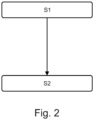
- Fig. 2 depicts a flowchart of a manufacturing method according to a preferred embodiment of the invention.
- This method comprises essentially two method steps:
- material comprising i) pre-reacted MgB 2 powder or ii) Mg powder and B powder on is arranged on the backing plate 2 for forming the coil pattern 3.
- step S1 material comprising i) pre-reacted MgB 2 powder or ii) Mg powder and B powder on is arranged on the backing plate 2 for forming the coil pattern 3.
- step S1 material comprising i) pre-reacted MgB 2 powder or ii) Mg powder and B powder on is arranged on the backing plate 2 for forming the coil pattern 3.
- the material is arranged on the backing plate 2 in such a way that the shape of the coil pattern 3 is already achieved, however not yet in a durable design.
- a durable design is only achieved in the second step S2 in which the arranged material is heat treated.
- the step of arranging pre-reacted MgB 2 powder or Mg powder and B powder on the backing plate 2 for forming the coil pattern 3 is performed by a press 8 which is schematically depicted in Fig. 4 :
- the material is arranged on the backing plate according to the shape of the coil pattern 3 and a press 8 is used to fix the material in that shape.
- the step of heat treating the arranged material is performed in an oven 9, wherein the oven 9 is equipped with a baker 10 with has a groove pattern 11 corresponding to the coil pattern 3.
- Fig. 5 shows the oven 9, the baker 10 and groove patterns 11 which relate to the shape of the coil pattern 3 as schematically shown in Fig. 1 .
Landscapes
- Physics & Mathematics (AREA)
- Condensed Matter Physics & Semiconductors (AREA)
- General Physics & Mathematics (AREA)
- Engineering & Computer Science (AREA)
- Manufacturing & Machinery (AREA)
- Electromagnetism (AREA)
- Magnetic Resonance Imaging Apparatus (AREA)
Priority Applications (2)
| Application Number | Priority Date | Filing Date | Title |
|---|---|---|---|
| EP23153106.2A EP4407335A1 (de) | 2023-01-24 | 2023-01-24 | Shimmen eines magnetresonanzbildgebungssystems |
| PCT/EP2024/050415 WO2024156501A1 (en) | 2023-01-24 | 2024-01-10 | Shimming a magnetic resonance imaging system |
Applications Claiming Priority (1)
| Application Number | Priority Date | Filing Date | Title |
|---|---|---|---|
| EP23153106.2A EP4407335A1 (de) | 2023-01-24 | 2023-01-24 | Shimmen eines magnetresonanzbildgebungssystems |
Publications (1)
| Publication Number | Publication Date |
|---|---|
| EP4407335A1 true EP4407335A1 (de) | 2024-07-31 |
Family
ID=85076176
Family Applications (1)
| Application Number | Title | Priority Date | Filing Date |
|---|---|---|---|
| EP23153106.2A Withdrawn EP4407335A1 (de) | 2023-01-24 | 2023-01-24 | Shimmen eines magnetresonanzbildgebungssystems |
Country Status (2)
| Country | Link |
|---|---|
| EP (1) | EP4407335A1 (de) |
| WO (1) | WO2024156501A1 (de) |
Citations (2)
| Publication number | Priority date | Publication date | Assignee | Title |
|---|---|---|---|---|
| WO2015189786A1 (en) * | 2014-06-11 | 2015-12-17 | Victoria Link Ltd | Transportable magnetic resonance imaging system |
| US10460862B2 (en) | 2014-11-28 | 2019-10-29 | Hitachi, Ltd. | Magnesium diboride superconducting thin-film wire and method for producing same |
Family Cites Families (2)
| Publication number | Priority date | Publication date | Assignee | Title |
|---|---|---|---|---|
| JPH01147812A (ja) * | 1987-12-04 | 1989-06-09 | Asahi Chem Ind Co Ltd | 超伝導性複合酸化物コイル |
| JPH02271506A (ja) * | 1989-04-12 | 1990-11-06 | Fujikura Ltd | 酸化物超電導シートコイルの製造方法 |
-
2023
- 2023-01-24 EP EP23153106.2A patent/EP4407335A1/de not_active Withdrawn
-
2024
- 2024-01-10 WO PCT/EP2024/050415 patent/WO2024156501A1/en not_active Ceased
Patent Citations (2)
| Publication number | Priority date | Publication date | Assignee | Title |
|---|---|---|---|---|
| WO2015189786A1 (en) * | 2014-06-11 | 2015-12-17 | Victoria Link Ltd | Transportable magnetic resonance imaging system |
| US10460862B2 (en) | 2014-11-28 | 2019-10-29 | Hitachi, Ltd. | Magnesium diboride superconducting thin-film wire and method for producing same |
Non-Patent Citations (3)
| Title |
|---|
| BALLARINO A ET AL: "Journal of Physics: Conference Series Status of MgB 2 wire and cable applications in Europe Status of MgB2 wire and cable applications in Europe", J. PHYS.: CONF. SER. JOURNAL OF PHYSICS: CONF. SERIES, vol. 871, no. 871, 1 January 2017 (2017-01-01), pages 12098, XP093027352, Retrieved from the Internet <URL:https://iopscience.iop.org/article/10.1088/1742-6596/871/1/012098/pdf> * |
| DONGKEUN PARK ET AL: "HTS Shim Coils Energized by a Flux Pump for the MIT 1.3-GHz LTS/HTS NMR Magnet: Design, Construction, and Results of a Proof-of-Concept Prototype", IEEE TRANSACTIONS ON APPLIED SUPERCONDUCTIVITY, vol. 28, no. 3, 1 April 2018 (2018-04-01), USA, pages 1 - 5, XP055687332, ISSN: 1051-8223, DOI: 10.1109/TASC.2018.2799182 * |
| PARK DONGKEUN ET AL: "Design of a Magnet and Gradient Coils for a Tabletop Liquid-Helium-Free, Persistent-Mode 1.5-T MgB$_2$ Osteoporosis MRI", IEEE TRANSACTIONS ON APPLIED SUPERCONDUCTIVITY, IEEE, USA, vol. 30, no. 4, 18 March 2020 (2020-03-18), pages 1 - 5, XP011783861, ISSN: 1051-8223, [retrieved on 20200413], DOI: 10.1109/TASC.2020.2981295 * |
Also Published As
| Publication number | Publication date |
|---|---|
| WO2024156501A1 (en) | 2024-08-02 |
Similar Documents
| Publication | Publication Date | Title |
|---|---|---|
| Ciovati et al. | Multi-metallic conduction cooled superconducting radio-frequency cavity with high thermal stability | |
| US8855731B2 (en) | Superconducting switch, superconducting magnet and MRI | |
| DE68907278T2 (de) | Supraleitender Magnetresonanz-Magnet. | |
| US8838193B2 (en) | Magnetic module | |
| EP0139189B1 (de) | Dauerstromschalter für supraleitende Hochenergie-Spulen | |
| EP3146351B1 (de) | Tragevorrichtung für eine supraleitende spule | |
| Yanagisawa et al. | Development of a persistent-mode NMR magnet with superconducting joints between high-temperature superconductors | |
| Brouwer et al. | Design of an achromatic superconducting magnet for a proton therapy gantry | |
| Li et al. | Key designs of a short-bore and cryogen-free high temperature superconducting magnet system for 14 T whole-body MRI | |
| Yokoyama et al. | Design and cooling properties of high stable field REBCO superconducting magnet for MRI | |
| Murtomäki et al. | Investigation of REBCO Roebel cable irreversible critical current degradation under transverse pressure | |
| EP4407335A1 (de) | Shimmen eines magnetresonanzbildgebungssystems | |
| Shao et al. | Experimental study on screening-current induced strain in REBCO insert coils: under critical current control and operation current cycles | |
| Rummel et al. | The Wendelstein 7-X trim coil system | |
| EP4530654A1 (de) | Konnektor für ein gerät zur untersuchung mittels magnetischer resonanz | |
| Chang et al. | Conduction-cooling system for superconducting magnets at 20–30 K | |
| JP2012064495A (ja) | 被覆超電導線材の製造方法、超電導線材被覆の電着方法、及び、被覆超電導線材 | |
| Wang et al. | Excitation and magnetic field performances of a prototype REBCO sextupole coil at 4.2 K | |
| KR102843501B1 (ko) | 초전도 자석용 초전도 스위치 | |
| Yokoyama et al. | Design of a half-size 3T REBCO superconducting magnet with active shielding coils for MRI | |
| Choi et al. | Conceptual design of current leads for a 21 T FT-ICR magnet system | |
| Madur et al. | Superconducting switch concept applied to superconducting undulator phase‐error correction | |
| DE102020210739A1 (de) | Magnetanordnung, die einen Hochtemperatur-Supraleiter zur Verwendung in einem Magnetresonanz-Bildgebungssystem umfasst | |
| EP3053172A1 (de) | Verfahren für ein gezieltes formen des magnetfelds von permanentmagneten | |
| US20250342993A1 (en) | Superconductor magnet systems and methods for generating magnetic fields |
Legal Events
| Date | Code | Title | Description |
|---|---|---|---|
| PUAI | Public reference made under article 153(3) epc to a published international application that has entered the european phase |
Free format text: ORIGINAL CODE: 0009012 |
|
| STAA | Information on the status of an ep patent application or granted ep patent |
Free format text: STATUS: THE APPLICATION HAS BEEN PUBLISHED |
|
| AK | Designated contracting states |
Kind code of ref document: A1 Designated state(s): AL AT BE BG CH CY CZ DE DK EE ES FI FR GB GR HR HU IE IS IT LI LT LU LV MC ME MK MT NL NO PL PT RO RS SE SI SK SM TR |
|
| STAA | Information on the status of an ep patent application or granted ep patent |
Free format text: STATUS: THE APPLICATION IS DEEMED TO BE WITHDRAWN |
|
| 18D | Application deemed to be withdrawn |
Effective date: 20250201 |