EP4407253A1 - Sonnenenergiespeicher und stromerzeugungssystem - Google Patents
Sonnenenergiespeicher und stromerzeugungssystem Download PDFInfo
- Publication number
- EP4407253A1 EP4407253A1 EP22880362.3A EP22880362A EP4407253A1 EP 4407253 A1 EP4407253 A1 EP 4407253A1 EP 22880362 A EP22880362 A EP 22880362A EP 4407253 A1 EP4407253 A1 EP 4407253A1
- Authority
- EP
- European Patent Office
- Prior art keywords
- housing
- energy storage
- generation system
- liquid
- solar energy
- Prior art date
- Legal status (The legal status is an assumption and is not a legal conclusion. Google has not performed a legal analysis and makes no representation as to the accuracy of the status listed.)
- Pending
Links
Images


Classifications
-
- H—ELECTRICITY
- H02—GENERATION; CONVERSION OR DISTRIBUTION OF ELECTRIC POWER
- H02S—GENERATION OF ELECTRIC POWER BY CONVERSION OF INFRARED RADIATION, VISIBLE LIGHT OR ULTRAVIOLET LIGHT, e.g. USING PHOTOVOLTAIC [PV] MODULES
- H02S40/00—Components or accessories in combination with PV modules, not provided for in groups H02S10/00 - H02S30/00
- H02S40/40—Thermal components
- H02S40/44—Means to utilise heat energy, e.g. hybrid systems producing warm water and electricity at the same time
-
- F—MECHANICAL ENGINEERING; LIGHTING; HEATING; WEAPONS; BLASTING
- F24—HEATING; RANGES; VENTILATING
- F24S—SOLAR HEAT COLLECTORS; SOLAR HEAT SYSTEMS
- F24S80/00—Details, accessories or component parts of solar heat collectors not provided for in groups F24S10/00-F24S70/00
- F24S80/60—Thermal insulation
-
- F—MECHANICAL ENGINEERING; LIGHTING; HEATING; WEAPONS; BLASTING
- F24—HEATING; RANGES; VENTILATING
- F24S—SOLAR HEAT COLLECTORS; SOLAR HEAT SYSTEMS
- F24S10/00—Solar heat collectors using working fluids
- F24S10/40—Solar heat collectors using working fluids in absorbing elements surrounded by transparent enclosures, e.g. evacuated solar collectors
-
- F—MECHANICAL ENGINEERING; LIGHTING; HEATING; WEAPONS; BLASTING
- F24—HEATING; RANGES; VENTILATING
- F24S—SOLAR HEAT COLLECTORS; SOLAR HEAT SYSTEMS
- F24S20/00—Solar heat collectors specially adapted for particular uses or environments
- F24S20/20—Solar heat collectors for receiving concentrated solar energy, e.g. receivers for solar power plants
-
- F—MECHANICAL ENGINEERING; LIGHTING; HEATING; WEAPONS; BLASTING
- F24—HEATING; RANGES; VENTILATING
- F24S—SOLAR HEAT COLLECTORS; SOLAR HEAT SYSTEMS
- F24S23/00—Arrangements for concentrating solar-rays for solar heat collectors
- F24S23/30—Arrangements for concentrating solar-rays for solar heat collectors with lenses
-
- F—MECHANICAL ENGINEERING; LIGHTING; HEATING; WEAPONS; BLASTING
- F24—HEATING; RANGES; VENTILATING
- F24S—SOLAR HEAT COLLECTORS; SOLAR HEAT SYSTEMS
- F24S23/00—Arrangements for concentrating solar-rays for solar heat collectors
- F24S23/70—Arrangements for concentrating solar-rays for solar heat collectors with reflectors
-
- F—MECHANICAL ENGINEERING; LIGHTING; HEATING; WEAPONS; BLASTING
- F24—HEATING; RANGES; VENTILATING
- F24S—SOLAR HEAT COLLECTORS; SOLAR HEAT SYSTEMS
- F24S40/00—Safety or protection arrangements of solar heat collectors; Preventing malfunction of solar heat collectors
- F24S40/10—Protective covers or shrouds; Closure members, e.g. lids
-
- F—MECHANICAL ENGINEERING; LIGHTING; HEATING; WEAPONS; BLASTING
- F24—HEATING; RANGES; VENTILATING
- F24S—SOLAR HEAT COLLECTORS; SOLAR HEAT SYSTEMS
- F24S40/00—Safety or protection arrangements of solar heat collectors; Preventing malfunction of solar heat collectors
- F24S40/20—Cleaning; Removing snow
-
- F—MECHANICAL ENGINEERING; LIGHTING; HEATING; WEAPONS; BLASTING
- F24—HEATING; RANGES; VENTILATING
- F24S—SOLAR HEAT COLLECTORS; SOLAR HEAT SYSTEMS
- F24S50/00—Arrangements for controlling solar heat collectors
- F24S50/20—Arrangements for controlling solar heat collectors for tracking
-
- F—MECHANICAL ENGINEERING; LIGHTING; HEATING; WEAPONS; BLASTING
- F24—HEATING; RANGES; VENTILATING
- F24S—SOLAR HEAT COLLECTORS; SOLAR HEAT SYSTEMS
- F24S60/00—Arrangements for storing heat collected by solar heat collectors
- F24S60/30—Arrangements for storing heat collected by solar heat collectors storing heat in liquids
-
- F—MECHANICAL ENGINEERING; LIGHTING; HEATING; WEAPONS; BLASTING
- F24—HEATING; RANGES; VENTILATING
- F24S—SOLAR HEAT COLLECTORS; SOLAR HEAT SYSTEMS
- F24S80/00—Details, accessories or component parts of solar heat collectors not provided for in groups F24S10/00-F24S70/00
- F24S80/40—Casings
-
- H—ELECTRICITY
- H02—GENERATION; CONVERSION OR DISTRIBUTION OF ELECTRIC POWER
- H02S—GENERATION OF ELECTRIC POWER BY CONVERSION OF INFRARED RADIATION, VISIBLE LIGHT OR ULTRAVIOLET LIGHT, e.g. USING PHOTOVOLTAIC [PV] MODULES
- H02S40/00—Components or accessories in combination with PV modules, not provided for in groups H02S10/00 - H02S30/00
- H02S40/20—Optical components
- H02S40/22—Light-reflecting or light-concentrating means
-
- F—MECHANICAL ENGINEERING; LIGHTING; HEATING; WEAPONS; BLASTING
- F24—HEATING; RANGES; VENTILATING
- F24S—SOLAR HEAT COLLECTORS; SOLAR HEAT SYSTEMS
- F24S30/00—Arrangements for moving or orienting solar heat collector modules
- F24S2030/10—Special components
- F24S2030/18—Load balancing means, e.g. use of counter-weights
-
- F—MECHANICAL ENGINEERING; LIGHTING; HEATING; WEAPONS; BLASTING
- F24—HEATING; RANGES; VENTILATING
- F24S—SOLAR HEAT COLLECTORS; SOLAR HEAT SYSTEMS
- F24S23/00—Arrangements for concentrating solar-rays for solar heat collectors
- F24S23/12—Light guides
-
- F—MECHANICAL ENGINEERING; LIGHTING; HEATING; WEAPONS; BLASTING
- F24—HEATING; RANGES; VENTILATING
- F24S—SOLAR HEAT COLLECTORS; SOLAR HEAT SYSTEMS
- F24S80/00—Details, accessories or component parts of solar heat collectors not provided for in groups F24S10/00-F24S70/00
- F24S80/50—Elements for transmitting incoming solar rays and preventing outgoing heat radiation; Transparent coverings
- F24S80/54—Elements for transmitting incoming solar rays and preventing outgoing heat radiation; Transparent coverings using evacuated elements
-
- H—ELECTRICITY
- H02—GENERATION; CONVERSION OR DISTRIBUTION OF ELECTRIC POWER
- H02S—GENERATION OF ELECTRIC POWER BY CONVERSION OF INFRARED RADIATION, VISIBLE LIGHT OR ULTRAVIOLET LIGHT, e.g. USING PHOTOVOLTAIC [PV] MODULES
- H02S20/00—Supporting structures for PV modules
- H02S20/30—Supporting structures being movable or adjustable, e.g. for angle adjustment
- H02S20/32—Supporting structures being movable or adjustable, e.g. for angle adjustment specially adapted for solar tracking
Definitions
- the present invention relates to solar thermal power generation, particularly a concentrated solar energy storage and power generation system that can improve the utilization rate of sunlight and achieve miniaturization.
- Concentrated Solar Power has been in development for decades, yet widespread adoption remains elusive.
- One contributing factor is the relatively low utilization rate of solar energy collection and conversion.
- energy is lost through reflection of the light energy received during conversion or saturation, while the receiver may also suffer significant convective heat loss when exposed to the atmosphere.
- manufacturing complexities and costs associated with large-scale, high-temperature power generation units can limit operating temperatures and notably impact conversion efficiency.
- installation requires a significant amount of space, and in the event of a fire, immediate shutdown and extinguishing of solar power is not feasible, making it impractical for urban environments. This also increases the cost of power transmission and poses a risk to birds and the environment due to high temperature light emissions.
- the purpose of the present invention is to provide a solar energy storage and generation system, particularly a concentrated solar energy storage and power generation system, which can improve the utilization rate of sunlight and achieve miniaturization.
- the solar energy storage and generation system comprises a housing mounted on a base, a solar collector installed inside the housing, and at least one lens installed on the upper surface of the housing.
- the housing is a hollow body having multiple liquid-level counterbalance devices separately installed at different corner positions inside the housing.
- the system further comprises at least one light path mechanism correspondingly disposed between the at least one lens and the solar collector for collecting the light incident on the at least one lens.
- the light path mechanism may be a light guide mirror assembly or a light guide tube assembly
- the system comprises a multi-axis adjustment device mounted on the base and corresponding to the center of gravity of the housing.
- the interior of the housing is a vacuum chamber.
- a thermal energy storage tank is installed inside the housing and is connected to a thermal conduction device of the solar collector.
- the thermal energy storage tank has an outlet pipe and an inlet pipe penetrating through a side surface of the housing.
- the liquid-level counterbalance device has a liquid-level adjustment controller for introducing liquid from an external water source into the liquid-level counterbalance device or discharging liquid from the liquid-level counterbalance device into a liquid storage tank.
- the system comprises a retractable shade installed on the housing for covering the upper surface of the housing, and a cleaning device is installed between the retractable shade and the housing.
- the solar collector comprises an absorber which is a hollow chamber.
- a solar energy system comprising a housing 10 mounted on a base 15.
- the housing 10 is a rectangular enclosure.
- the solar energy system includes a solar collector 30 installed within the housing 10, at least one lens 12 installed on the upper surface of the housing 10, the lens 12 preferably being a Fresnel lens and having a light absorption rate of less than 5%, and at least one light path mechanism correspondingly disposed between the at least one lens 12 and the solar collector 30 for collecting the light rays L incident on the at least one lens 12.
- the light path mechanism is spaced from the at least one lens 12.
- the interior of the housing 10 is a vacuum chamber for reducing light loss and achieving insulation.
- the solar collector 30 includes an absorber 31 connected to a thermal energy storage tank 32.
- the absorber 31 is a hollow spherical chamber, and its inner surface has an absorbing layer (not shown) capable of achieving at least 95% light absorption.
- the material of the absorbing layer may be, but is not limited to, graphite, tungsten carbide, carbon nanotubes, or nanomaterials.
- the solar collector 30 is not limited to the aforementioned structure and may be any form of solar collector 30.
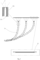
- the light path mechanism is a light guide tube assembly comprising multiple spaced light guide tubes 21.
- the portion of each light guide tube 21 near the upper surface of the housing 10 is composed of multiple spaced tubes.
- One end of the light guide tube assembly is connected to the absorber 31 of the solar collector 30, and the other end is spaced apart from the lens 12 by a distance approximately equal to the focal length of the lens 12, thereby reducing the inner diameter of the light guide tube 21.
- a reflecting layer 21a is arranged on the inner surface of the light guide tube 21 to receive the light rays L reflected from the lens 12, and an insulating layer 21b is arranged on the outer surface of the light guide tube 21.
- the insulating layer 21b has characteristics of low thermal conductivity, low radiation loss, and high-temperature resistance.
- the material of the insulating layer 21b may be, but is not limited to, zirconia, diatomaceous earth, ceramic wool, porous composites, or nanomaterials.
- the housing 10 can be mounted on the base 15 with the solar collector 30 installed inside the housing 10.
- the solar collector 30 has the absorber 31 connected to the thermal energy storage tank 32, which has an outlet pipe 321 and an inlet pipe 322 penetrating through a side surface of the housing 10, and external liquid enters the thermal energy storage tank 32 through the inlet pipe 322.
- the thermal energy storage tank 32 contacts the absorber 31 of the solar collector 30, the temperature of the absorber 31 is transferred to the thermal energy storage tank 32, causing the liquid in the thermal energy storage tank 32 to heat up and evaporate.
- the gas then flows out through the outlet pipe 321 to a power generation device (not shown) and drives the power generation device to generate electricity by fluid kinetic energy or can be used for seawater desalination or steam reforming to produce hydrogen, among other applications.
- the upper surface of the housing 10 is oriented toward the sun.
- the light rays L are refracted and focused by the lens 12 into the light guide tube 21, and undergo multiple reflections by the reflecting layer 21a before entering the interior of the absorber 31 of the solar collector 30.
- the light rays L contact the absorbing layer of the absorber 31 and continue to undergo multiple reflections inside the absorber 31 while the absorbing layer converts the light rays L into thermal energy.
- the absorber 31 conducts the thermal energy to the thermal energy storage tank 32, which then transfers the thermal energy through the outlet pipe 321 to external facilities for applications such as heating water in a storage tank for hot water use.
- the direct contact between the absorber 31 and the thermal energy storage tank 32 reduces heat loss during the thermal energy transfer process.
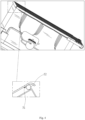
- the upper surface of the housing 10 is also provided with a retractable shade 50 that can cover the upper surface of the housing 10.
- the retractable shade 50 can be used to block sunlight and prevent heat generation.
- a cleaning device is also installed between the retractable shade 50 and the upper surface of the housing 10.
- the cleaning device may be a roller brush 52 and/or a sprayer 51.
- the retractable shade 50 can be pulled up to cover the upper surface of the housing 10, not only to block sunlight and prevent the solar collector 30 from being burned, but also to protect the housing 10 from damage caused by sand, hail, or other foreign objects.
- retractable shade 50 As the retractable shade 50 is raised or lowered, it also cleans the surface of the housing 10.
- the winding direction of the retractable shade 50 is downward, so that any foreign objects on the retractable shade 50 fall due to gravity during the winding process, thereby achieving a self-cleaning effect.
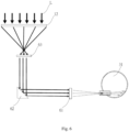
- the multiple lenses 12 are installed on the upper surface of the housing 10, and the light path mechanism is a light guide mirror assembly.
- the light path between each lens 12 and the solar collector 30 sequentially comprises at least one focal length conversion lens 63, at least one reflector 62, and at least one focusing lens 61 installed inside the housing 10.
- the focal length conversion lens 63 is positioned relatively closer to the lens 12
- the focusing lens 61 is positioned relatively closer to the solar collector 30, and the reflector 62 is positioned between the focal length conversion lens 63 and the focusing lens 61.
- high, medium, and low temperature zones are formed between the absorber 31, the light path mechanism, and the lens 12, allowing for more effective selection of light-collecting materials to reduce costs.
- FIG. 6 which illustrates the light path of the light rays L through the light path mechanism and into the solar collector.
- the light rays L are refracted through the lens 12 and enter the housing 10, they are refracted by the focal length conversion lens 63 toward the reflector 62, reflected by the reflector 62 toward the focusing lens 61, and then focused by the focusing lens 61 into the absorber 31.
- the light rays L are repeatedly reflected and absorbed within the solar collector 30, generating thermal energy which is conducted by the absorber 31 to the thermal energy storage tank 32 and then transferred through the outlet pipe 321 to external facilities for applications such as heating water in a storage tank for hot water use.
- the solar collector 30 comprises an absorber 41 connected to a thermal conduction trough 42, a thermal conduction device 43 installed in the thermal conduction trough 42, which may be, but is not limited to, a heat pipe, and a thermoelectric module 44 disposed between the thermal conduction trough 42 and the thermal conduction device 43.
- the absorber 41 is a hollow spherical chamber, the thermal conduction trough 42 at the top of the absorber 41 is filled with a heat transfer medium and is connected to either the hot end of the thermoelectric module 44 or the thermal conduction device 43, and when the thermoelectric module 44 is equipped, the thermal conduction device 43 is connected to the cold end of the thermoelectric module 44.
- the light rays L are refracted through the lens 12 and enter the housing 10, they are repeatedly reflected and absorbed in the absorber 41, thereby generating thermal energy. This thermal energy is then transferred through the heat transfer medium to the thermoelectric module 44 or the thermal conduction device 43, which conducts the thermal energy to the thermal energy storage tank 32 or external facilities.
- the solar collector 30 is not limited to the aforementioned structure and may be any form of solar collector.
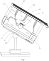
- the housing 10 is a rectangular enclosure with a multi-axis adjustment device 151 mounted on the base 15 and positioned corresponding to the center of gravity of the housing 10 (i.e., the intersection of the diagonal lines), thereby facilitating the adjustment of the angle of the housing 10.
- a multi-axis adjustment device 151 mounted on the base 15 and positioned corresponding to the center of gravity of the housing 10 (i.e., the intersection of the diagonal lines), thereby facilitating the adjustment of the angle of the housing 10.
- four liquid-level counterbalance devices 70 are installed at the four corners inside the housing 10, and the liquid-level counterbalance device 70 is a water tank. As the sun rises in the east and sets in the west, the liquid-level counterbalance devices 70 are used in conjunction with the multi-axis adjustment device 151 to fully collect the sunlight.
- the housing 10 can be oriented at different angles. For example, when the sun is shining from the right side of the housing 10, the liquid level in the two water tanks on the right side of the housing 10 is controlled to be greater than the liquid level in the two water tanks on the left side, causing the housing 10 to tilt to the right. This allows the upper surface of the housing 10 to face the position of the sun to fully collect sunlight and achieve a sun-tracking effect.
- the number of liquid-level counterbalance devices 70 can be two, installed at the midpoints of the two lengths or the two widths of the interior of the housing 10 to achieve the same effect of orienting the upper surface of the housing 10 toward the position of the sun.
- the housing 10 may also be other symmetrical geometric structures.
- the liquid-level counterbalance device 70 also includes a liquid-level adjustment controller.
- the liquid-level counterbalance device 70 is connected to an external water source 72 and a liquid storage tank 74.
- the liquid-level adjustment controller is used to control the inflow and outflow of liquid in the water tank, introducing liquid from the external water source 72 into the water tank or discharging liquid from the water tank into the liquid storage tank 74 for resource reuse, thereby controlling the tilt angle of the housing 10 to achieve the sun-tracking effect.
- the tilt angle of the housing 10 can be adjusted to achieve the sun-tracking function without using a power motor and saving energy consumption.
- the adjustment controller can be controlled to drain some of the liquid from the water tanks to allow the housing 10 to return to its initial morning position.
- the present invention achieves a miniaturized and high-sunlight-utilization solar energy storage and power generation system by mounting the housing 10 on the base 15 having the multi-axis adjustment device 151, using the liquid-level adjustment controller to control the liquid volume in the liquid-level counterbalance devices 70, and incorporating the high efficiency light-collecting solar collector, thereby controlling the orientation of the upper surface of the housing 10 toward the position of the sun for sun-tracking.
Landscapes
- Engineering & Computer Science (AREA)
- Physics & Mathematics (AREA)
- Life Sciences & Earth Sciences (AREA)
- Sustainable Development (AREA)
- Sustainable Energy (AREA)
- Thermal Sciences (AREA)
- Chemical & Material Sciences (AREA)
- Combustion & Propulsion (AREA)
- Mechanical Engineering (AREA)
- General Engineering & Computer Science (AREA)
- Photovoltaic Devices (AREA)
Applications Claiming Priority (2)
| Application Number | Priority Date | Filing Date | Title |
|---|---|---|---|
| CN202111197780.XA CN115978808A (zh) | 2021-10-14 | 2021-10-14 | 太阳能储能及发电系统 |
| PCT/CN2022/125028 WO2023061426A1 (zh) | 2021-10-14 | 2022-10-13 | 太阳能储能及发电系统 |
Publications (2)
| Publication Number | Publication Date |
|---|---|
| EP4407253A1 true EP4407253A1 (de) | 2024-07-31 |
| EP4407253A4 EP4407253A4 (de) | 2025-09-17 |
Family
ID=85964797
Family Applications (1)
| Application Number | Title | Priority Date | Filing Date |
|---|---|---|---|
| EP22880362.3A Pending EP4407253A4 (de) | 2021-10-14 | 2022-10-13 | Sonnenenergiespeicher und stromerzeugungssystem |
Country Status (8)
| Country | Link |
|---|---|
| US (1) | US20240348203A1 (de) |
| EP (1) | EP4407253A4 (de) |
| JP (1) | JP7778421B2 (de) |
| CN (1) | CN115978808A (de) |
| AU (1) | AU2022365135B2 (de) |
| MX (1) | MX2024004491A (de) |
| WO (1) | WO2023061426A1 (de) |
| ZA (1) | ZA202402694B (de) |
Family Cites Families (19)
| Publication number | Priority date | Publication date | Assignee | Title |
|---|---|---|---|---|
| US4132223A (en) * | 1977-09-06 | 1979-01-02 | Reddell E Garland | Tracking system for solar energy collector |
| CH635417A5 (en) * | 1978-05-01 | 1983-03-31 | Paul Leuenberger | Solar heat collector |
| US4220136A (en) * | 1978-09-13 | 1980-09-02 | Penney Richard J | Solar energy collector |
| US4349011A (en) * | 1981-05-22 | 1982-09-14 | Hartsog Clarence E | Solar operated shutter |
| CZ20022831A3 (cs) * | 2000-01-27 | 2003-12-17 | Michael Bohumir Haber | Mechanismus naklánění souboru sad solárních panelů |
| PE20090843A1 (es) * | 2007-07-10 | 2009-07-24 | Trevijano Jose Javier Alejo | Concentrador de energia solar y proceso de montaje |
| EP2326886B1 (de) * | 2008-09-25 | 2017-05-31 | Solfast Pty Ltd | Sonnenkollektor |
| US8113193B2 (en) * | 2009-01-05 | 2012-02-14 | Kenergy Scientific, Inc. | Reciprocating solar engine with attached solar windows |
| CN201412975Y (zh) * | 2009-02-18 | 2010-02-24 | 赵风雏 | 移动式太阳能开水炉 |
| US20100229916A1 (en) * | 2009-03-12 | 2010-09-16 | Geraldine Bechamp | Protection system |
| US20110079267A1 (en) * | 2009-10-02 | 2011-04-07 | Genie Lens Technologies, Llc | Lens system with directional ray splitter for concentrating solar energy |
| WO2011141198A2 (en) * | 2010-05-14 | 2011-11-17 | Rahmi Oguz Capan | A solar energy system |
| CN102455062A (zh) * | 2010-10-24 | 2012-05-16 | 张先锋 | 凹面镜反射聚光锁阳吸热式太阳光热能收集方法和装置 |
| US9821475B1 (en) * | 2012-10-26 | 2017-11-21 | Other Lab, Llc | Robotic actuator |
| CN204848256U (zh) * | 2015-08-11 | 2015-12-09 | 中国矿业大学 | 一种太阳能氢气制取装置 |
| CN105716298A (zh) * | 2015-11-18 | 2016-06-29 | 南京安纳杰能源科技有限公司 | 太阳能光纤供热传输应用系统 |
| CN109462003A (zh) * | 2018-10-11 | 2019-03-12 | 江苏三和欣创通信科技有限公司 | 一种基于全频段的测量天线系统 |
| CN109672398B (zh) * | 2018-11-23 | 2020-10-02 | 山东理工昊明新能源有限公司 | 一种新型可调式弧形太阳能装置 |
| CN210920766U (zh) * | 2019-08-30 | 2020-07-03 | 绍兴市金桥伞业有限公司 | 一种万向伞底座 |
-
2021
- 2021-10-14 CN CN202111197780.XA patent/CN115978808A/zh active Pending
-
2022
- 2022-10-13 US US18/701,090 patent/US20240348203A1/en active Pending
- 2022-10-13 MX MX2024004491A patent/MX2024004491A/es unknown
- 2022-10-13 WO PCT/CN2022/125028 patent/WO2023061426A1/zh not_active Ceased
- 2022-10-13 AU AU2022365135A patent/AU2022365135B2/en active Active
- 2022-10-13 JP JP2024519919A patent/JP7778421B2/ja active Active
- 2022-10-13 EP EP22880362.3A patent/EP4407253A4/de active Pending
-
2024
- 2024-04-08 ZA ZA2024/02694A patent/ZA202402694B/en unknown
Also Published As
| Publication number | Publication date |
|---|---|
| WO2023061426A1 (zh) | 2023-04-20 |
| CN115978808A (zh) | 2023-04-18 |
| JP2024535485A (ja) | 2024-09-30 |
| AU2022365135B2 (en) | 2025-09-04 |
| ZA202402694B (en) | 2024-11-27 |
| US20240348203A1 (en) | 2024-10-17 |
| EP4407253A4 (de) | 2025-09-17 |
| JP7778421B2 (ja) | 2025-12-02 |
| MX2024004491A (es) | 2024-05-03 |
| AU2022365135A1 (en) | 2024-04-18 |
Similar Documents
| Publication | Publication Date | Title |
|---|---|---|
| CN1773190B (zh) | 一种太阳能热电联供系统 | |
| EP2857775A1 (de) | Fotothermischen solarempfangsvorrichtung | |
| CN103199743A (zh) | 一种可控双状态反光聚光太阳能集热发电装置 | |
| CN102803723B (zh) | 用于太阳能收集和自然通风冷却的塔 | |
| CN218627049U (zh) | 一种聚光太阳能集热装置 | |
| EP4407253A1 (de) | Sonnenenergiespeicher und stromerzeugungssystem | |
| CN111981710B (zh) | 具有储热能力的塔式太阳能吸热器 | |
| RU94316U1 (ru) | Панель солнечного коллектора | |
| CN202562086U (zh) | 一种槽式太阳能光热光电转化器 | |
| KR20100067519A (ko) | 태양열 집열 진공관 | |
| CN111510063A (zh) | 一种点阵式太阳能收集装置 | |
| TWI831716B (zh) | 太陽能儲能系統 | |
| TWI834069B (zh) | 太陽能儲能系統 | |
| CN213119568U (zh) | 具有储热能力的塔式太阳能吸热器 | |
| CN211476322U (zh) | 一种外挂式聚焦太阳能热水装置 | |
| CN102242976A (zh) | 太阳能热收集器 | |
| CN113551435A (zh) | 一种建筑节能太阳能蓄热供水系统 | |
| CN218544573U (zh) | 可实现供热导光的装配式蒙古包 | |
| TWI321639B (en) | A compound arc light-concentrating and heat-collecting device | |
| CN202149624U (zh) | 太阳能热收集器 | |
| RU90884U1 (ru) | Солнечный коллектор | |
| Gee et al. | Operation and Preliminary Performance of the Duke Solar Power Roof™: A Roof-Integrated Solar Cooling and Heating System | |
| WO2018210331A1 (zh) | 一种两次点聚焦的太阳能收集装置 | |
| CN209484863U (zh) | 新型集成式聚光集热装置 | |
| JP2014081186A (ja) | 太陽熱集熱方法および太陽熱集熱装置 |
Legal Events
| Date | Code | Title | Description |
|---|---|---|---|
| STAA | Information on the status of an ep patent application or granted ep patent |
Free format text: STATUS: THE INTERNATIONAL PUBLICATION HAS BEEN MADE |
|
| PUAI | Public reference made under article 153(3) epc to a published international application that has entered the european phase |
Free format text: ORIGINAL CODE: 0009012 |
|
| STAA | Information on the status of an ep patent application or granted ep patent |
Free format text: STATUS: REQUEST FOR EXAMINATION WAS MADE |
|
| 17P | Request for examination filed |
Effective date: 20240409 |
|
| AK | Designated contracting states |
Kind code of ref document: A1 Designated state(s): AL AT BE BG CH CY CZ DE DK EE ES FI FR GB GR HR HU IE IS IT LI LT LU LV MC ME MK MT NL NO PL PT RO RS SE SI SK SM TR |
|
| DAV | Request for validation of the european patent (deleted) | ||
| DAX | Request for extension of the european patent (deleted) | ||
| A4 | Supplementary search report drawn up and despatched |
Effective date: 20250820 |
|
| RIC1 | Information provided on ipc code assigned before grant |
Ipc: F24S 10/40 20180101AFI20250813BHEP Ipc: F24S 80/40 20180101ALI20250813BHEP Ipc: F24S 40/10 20180101ALI20250813BHEP Ipc: F24S 40/20 20180101ALI20250813BHEP Ipc: F24S 20/20 20180101ALI20250813BHEP Ipc: F24S 23/30 20180101ALI20250813BHEP Ipc: F24S 23/70 20180101ALI20250813BHEP Ipc: F24S 60/30 20180101ALI20250813BHEP Ipc: F24S 80/60 20180101ALI20250813BHEP Ipc: F24S 30/00 20180101ALI20250813BHEP Ipc: F24S 50/20 20180101ALN20250813BHEP |