EP4407242A1 - Indoor unit and air conditioner - Google Patents
Indoor unit and air conditioner Download PDFInfo
- Publication number
- EP4407242A1 EP4407242A1 EP22875436.2A EP22875436A EP4407242A1 EP 4407242 A1 EP4407242 A1 EP 4407242A1 EP 22875436 A EP22875436 A EP 22875436A EP 4407242 A1 EP4407242 A1 EP 4407242A1
- Authority
- EP
- European Patent Office
- Prior art keywords
- refrigerant pipe
- pipe
- refrigerant
- liquid
- indoor unit
- Prior art date
- Legal status (The legal status is an assumption and is not a legal conclusion. Google has not performed a legal analysis and makes no representation as to the accuracy of the status listed.)
- Granted
Links
Images



Classifications
-
- F—MECHANICAL ENGINEERING; LIGHTING; HEATING; WEAPONS; BLASTING
- F24—HEATING; RANGES; VENTILATING
- F24F—AIR-CONDITIONING; AIR-HUMIDIFICATION; VENTILATION; USE OF AIR CURRENTS FOR SCREENING
- F24F1/00—Room units for air-conditioning, e.g. separate or self-contained units or units receiving primary air from a central station
- F24F1/0007—Indoor units, e.g. fan coil units
- F24F1/0059—Indoor units, e.g. fan coil units characterised by heat exchangers
- F24F1/0067—Indoor units, e.g. fan coil units characterised by heat exchangers by the shape of the heat exchangers or of parts thereof, e.g. of their fins
-
- F—MECHANICAL ENGINEERING; LIGHTING; HEATING; WEAPONS; BLASTING
- F24—HEATING; RANGES; VENTILATING
- F24F—AIR-CONDITIONING; AIR-HUMIDIFICATION; VENTILATION; USE OF AIR CURRENTS FOR SCREENING
- F24F1/00—Room units for air-conditioning, e.g. separate or self-contained units or units receiving primary air from a central station
- F24F1/06—Separate outdoor units, e.g. outdoor unit to be linked to a separate room comprising a compressor and a heat exchanger
- F24F1/26—Refrigerant piping
- F24F1/32—Refrigerant piping for connecting the separate outdoor units to indoor units
-
- F—MECHANICAL ENGINEERING; LIGHTING; HEATING; WEAPONS; BLASTING
- F24—HEATING; RANGES; VENTILATING
- F24F—AIR-CONDITIONING; AIR-HUMIDIFICATION; VENTILATION; USE OF AIR CURRENTS FOR SCREENING
- F24F1/00—Room units for air-conditioning, e.g. separate or self-contained units or units receiving primary air from a central station
- F24F1/0007—Indoor units, e.g. fan coil units
- F24F1/0068—Indoor units, e.g. fan coil units characterised by the arrangement of refrigerant piping outside the heat exchanger within the unit casing
Definitions
- the present disclosure relates to an indoor unit and an air conditioner.
- Examples of a known indoor unit include an indoor unit in which a connection portion between a first refrigerant pipe formed of aluminum or an aluminum alloy and a second refrigerant pipe formed of copper or a copper alloy is disposed at a falling portion of the first refrigerant pipe, and the first refrigerant pipe is entirely covered with a heat insulating material for corrosion prevention (see, for example, JP 2013-155892 A (Patent Literature 1)).
- Patent Literature 1 JP 2013-155892 A
- the dissimilar metals of the first and second refrigerant pipes are connected to each other outside a casing, and dew condensation is likely to occur in the refrigerant pipes due to exposure to indoor air. Therefore, an anti-dew tube that covers the refrigerant pipes is provided. It is difficult to keep the inside of the anti-dew tube dry, which keeps the connection portion between the first and second refrigerant pipes wet for a long period of time and causes the connection portion to suffer electrolytic corrosion.
- the present disclosure proposes an indoor unit capable of preventing a refrigerant pipe from suffering electrolytic corrosion, and an air conditioner including the indoor unit.
- An indoor unit of the present disclosure includes:
- a connection point between the first refrigerant pipe and the second refrigerant pipe is located in an internal space of the casing, the inner space is not covered with an anti-dew tube or the like, so that it is possible to prevent the connection point from suffering dew condensation and thus prevent the refrigerant pipes from suffering electrolytic corrosion.
- the other end of the first refrigerant pipe is located above the one end of the second refrigerant pipe.
- the other end of the first refrigerant pipe is located above the one end of the second refrigerant pipe, so that even when dew condensation occurs in the second refrigerant pipe, dew condensation water does not flow to the first refrigerant pipe, and it is therefore possible to reliably prevent the occurrence of electrolytic corrosion.
- the indoor unit further includes a tubular member that covers a part of the connection pipe but does not cover the other part of the connection pipe, in which in the other part, the second refrigerant pipe has the one end connected to the other end of the first refrigerant pipe.
- a connection portion where the one end of the second refrigerant pipe is connected to the other end of the first refrigerant pipe is not covered with the tubular member, so that it is possible to reduce the risk of the occurrence of electrolytic corrosion due to dew condensation water accumulated in the tubular member.
- the second refrigerant pipe includes a bent section that is bent to protrude downward, and the bent section is disposed in the casing.
- the bent section that is bent to protrude downward from the second refrigerant pipe is disposed in the inner space of the casing, so that dew condensation water generated in the second refrigerant pipe drops from the bent section without flowing from the second refrigerant pipe to the first refrigerant pipe. Therefore, it is possible to reliably prevent the occurrence of electrolytic corrosion.
- connection pipe includes a first connection pipe and a second connection pipe
- first connection pipe includes:
- connection pipe includes a first connection pipe and a second connection pipe
- first connection pipe and the second connection pipe include the first refrigerant pipe and the second refrigerant pipe respectively.
- the first connection pipe is a liquid pipe and the second connection pipe is a gas pipe, and the other end of the first-first refrigerant pipe is disposed above the one end of the second-second refrigerant pipe in the casing.
- the liquid pipe is a refrigerant pipe connected to an inlet of an evaporator (heat exchanger during cooling operation or dehumidifying operation), and the gas pipe is a refrigerant pipe connected to an outlet of the evaporator.
- the other end of the first-first refrigerant pipe that is a liquid pipe is disposed above the one end of the second-second refrigerant pipe that is a gas pipe. That is, an amount of dew condensation that occurs on the second-second refrigerant pipe is larger than one that occurs on the first-first refrigerant pipe, the second-second refrigerant pipe being disposed below the first-first refrigerant pipe. Therefore, it is possible to prevent the first-first refrigerant pipe located above from suffering electrolytic corrosion.
- the first-first refrigerant pipe is disposed so as not to overlap the second-second refrigerant pipe as the casing is viewed from above.
- the first-first refrigerant pipe and the second-second refrigerant pipe do not overlap each other as viewed from above, so that it is possible to prevent dew condensation water dropped from the second-second refrigerant pipe from hitting the first-first refrigerant pipe and thus prevent the first-first refrigerant pipe from suffering electrolytic corrosion.
- the bent section is disposed so as not to overlap an electric component in the casing as the casing is viewed from above.
- the bent section of the second refrigerant pipe and the electric component do not overlap each other as viewed from above, so that it is possible to prevent dew condensation water dropped from the second refrigerant pipe from hitting the electric component.
- the second refrigerant pipe has the one end connected to the other end of the first refrigerant pipe above a drain pan provided in the casing.
- the drain pan can receive dew condensation water dropped from the connection portion where the one end of the second refrigerant pipe is connected to the other end of the first refrigerant pipe and drain the dew condensation water together with drain water.
- An air conditioner of the present disclosure includes any one of the indoor units.
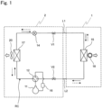
- Fig. 1 is a diagram illustrating a refrigerant circuit RC provided in an air conditioner including an indoor unit 1 of a first embodiment of the present disclosure.
- the air conditioner of the first embodiment includes the indoor unit 1 and an outdoor unit 2 connected to the indoor unit 1 via the refrigerant circuit RC.
- the air conditioner is of a type in which the outdoor unit 2 is paired one-to-one with the indoor unit 1.
- the refrigerant circuit RC includes a compressor 11, a four-way switching valve 12, an outdoor heat exchanger 13, an electric expansion valve 14, an indoor heat exchanger 15, and an accumulator 16.
- a refrigerant for example, an HFC refrigerant such as R410A or R32
- the indoor heat exchanger 15 is an example of a heat exchanger.
- the four-way switching valve 12 has one end connected to a discharge side of the compressor 11.
- the four-way switching valve 12 has the other end connected to one end of the outdoor heat exchanger 13.
- the outdoor heat exchanger 13 has the other end connected to one end of the electric expansion valve 14.
- the electric expansion valve 14 has the other end connected to one end of the indoor heat exchanger 15 via a shutoff valve V 1 and a connection pipe L1.
- the indoor heat exchanger 15 has the other end connected to one end of the accumulator 16 via a connection pipe L2, a shutoff valve V2, and the four-way switching valve 12.
- the accumulator 16 has the other end connected to an intake-side portion of the compressor 11.
- the indoor unit 1 is equipped with the indoor heat exchanger 15 and an indoor fan 18.
- the indoor fan 18 is, for example, a cross-flow fan, and takes in indoor air through the indoor heat exchanger 15.
- the outdoor unit 2 is equipped with the compressor 11, the four-way switching valve 12, the outdoor heat exchanger 13, the electric expansion valve 14, the accumulator 16, and an outdoor fan 17.
- the air conditioner switches the four-way switching valve 12 to a switching position indicated by a solid line to activate the compressor 11 for cooling operation and dehumidifying operation, and switches the four-way switching valve 12 to a switching position indicated by a dotted line to activate the compressor 11 for heating operation.
- a direction of a solid arrow in Fig. 1 indicates a direction in which the refrigerant flows during the cooling operation and the dehumidifying operation.
- a direction indicated by a dotted arrow in Fig. 1 indicates a direction in which the refrigerant flows during the heating operation.
- Fig. 2 is a perspective view of the indoor unit 1 as viewed obliquely from above
- Fig. 3 is a front view of the indoor unit 1.
- the indoor unit 1 includes a casing 21, and the indoor heat exchanger 15 (illustrated in Fig. 1 ), the indoor fan 18 (illustrated in Fig. 1 ), and the like are accommodated in the casing 21.
- An upper portion of the casing 21 is provided with an intake port 22 through which indoor air is taken in.
- indoor air enters the casing 21 through the intake port 22 and flows toward the indoor fan 18 (cross-flow fan).
- a filter (not illustrated) is attached to the intake port 22.
- a lower portion of the casing 21 is provided with a blow-out port 23 through which air from the indoor fan 18 (indoor air subjected to heat exchange with the indoor heat exchanger 15) blows out.
- a horizontal flap 24 is rotatably attached to a peripheral edge portion of the blow-out port 23.
- the horizontal flap 24 changes its position from a stop position to close the blow-out port 23 to an operation position to open the blow-out port 23 to adjust a vertical airflow direction of air blown out from the blow-out port 23.
- Fig. 4 is a rear perspective view of the indoor unit 1
- Fig. 5 is a cross-sectional view taken along line V-V in Fig. 3 .
- a reference numeral 28 denotes an electric component portion.
- the casing 21 of the indoor unit 1 includes a bottom frame 25, a front grille 26 attached to the bottom frame 25 and having a substantially rectangular opening (not illustrated) provided on a front surface, and a front panel 27 attached to cover the opening of the front grille 26.
- the front grille 26 surrounds a front surface, an upper surface, a lower surface, and both side surfaces of the bottom frame 25.
- a rear surface of the bottom frame 25 is attached to an indoor wall surface with an attachment plate (not illustrated) interposed between the rear surface and the indoor wall surface.
- a first space 21a surrounded by the bottom frame 25, the front grille 26, and the front panel 27 is formed.
- the first space 21a is a main area in the casing 21.
- An inner section of a liquid-refrigerant connection pipe 31 and an inner section of a gas-refrigerant connection pipe 32 are accommodated in the first space 21a.
- a second space 30a (pipe rising portion) is formed on a right side of the bottom frame 25 along an up-down direction.
- a third space 30b is formed, extending in a left-right direction, on the rear surface of and below the bottom frame 25 so as to be continuous with a lower end of the second space 30a.
- the liquid-refrigerant connection pipe 31 and the gas-refrigerant connection pipe 32 are disposed extending from the indoor heat exchanger 15 in the first space 21a along the second space 30a and the third space 30b.
- a vertical section of the liquid-refrigerant connection pipe 31 and a vertical section of the gas-refrigerant connection pipe 32 are accommodated in the second space 30a.
- a horizontal section of the liquid-refrigerant connection pipe 31 and a horizontal section of the gas-refrigerant connection pipe 32 are accommodated in the third space 30b.
- the liquid-refrigerant connection pipe 31 and the gas-refrigerant connection pipe 32 are led out of the casing 21 from a space above a drain pan 29 (illustrated in Figs. 7 and 8 ) provided in the bottom frame 25.
- the second space 30a and the third space 30b are not located in the casing 21 and are located outside of the rear of the bottom frame 25, i.e., are a space behind the bottom frame 25. In other words, the second space 30a and the third space 30b are located outside the casing 21.
- Fig. 6 is a front view of the indoor heat exchanger 15, the liquid-refrigerant connection pipe 31, and the gas-refrigerant connection pipe 32.
- the indoor heat exchanger 15 includes a heat exchange portion 151 and a plurality of heat transfer tubes 152 extending through the heat exchange portion 151 in a left-right direction.
- the heat exchange portion 151 and the heat transfer tubes 152 are each formed of aluminum or an aluminum alloy.
- the indoor unit 1 further includes the liquid-refrigerant connection pipe 31 and the gas-refrigerant connection pipe 32, the liquid-refrigerant connection pipe 31 and the gas-refrigerant connection pipe 32 being fluidly connected to the heat transfer tubes 152 of the indoor heat exchanger 15.
- the liquid-refrigerant connection pipe 31 is an example of a first connection pipe, and constitutes a part of the connection pipe L1 (illustrated in Fig. 1 ).
- the gas-refrigerant connection pipe 32 is an example of a second connection pipe, and constitutes a part of the connection pipe L2 (illustrated in Fig. 1 ).
- the liquid-refrigerant connection pipe 31 guides a liquid refrigerant from the electric expansion valve 14 to the indoor heat exchanger 15 during the cooling operation and the dehumidifying operation.
- the gas-refrigerant connection pipe 32 guides a gas refrigerant from the indoor heat exchanger 15 to the compressor 11 during the cooling operation and the dehumidifying operation.
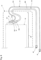
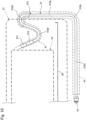
- Fig. 7 is a schematic front view of a main portion of the indoor heat exchanger
- Fig. 8 is a schematic front view of the main portion of the indoor heat exchanger
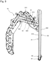
- Fig. 9 is a right-side view of the indoor heat exchanger 15, the liquid-refrigerant connection pipe 31, and the gas-refrigerant connection pipe 32.
- a reference numeral 29 denotes the drain pan disposed in the casing 21 and below the indoor heat exchanger 15.
- a tubular member 61 is not illustrated.
- the liquid-refrigerant connection pipe 31 includes a first liquid-refrigerant pipe 311 formed of aluminum or an aluminum alloy, a second liquid-refrigerant pipe 312 formed of copper or a copper alloy, and a connection portion 313 formed of copper or a copper alloy that connects between the first liquid-refrigerant pipe 311 and the second liquid-refrigerant pipe 312.
- the first liquid-refrigerant pipe 311 is an example of a first refrigerant pipe and a first-first refrigerant pipe
- the second liquid-refrigerant pipe 312 is an example of a second refrigerant pipe and a second-first refrigerant pipe.
- the aluminum and the aluminum alloy are each an example of a first metal.
- the copper and the copper alloy are each an example of a second metal.
- the second liquid-refrigerant pipe 312 has one end connected to one end of the connection portion 313 by copper-copper bonding.
- the connection portion 313 has the other end connected to the heat transfer tube 152 of the indoor heat exchanger 15 through the first liquid-refrigerant pipe 311 formed of aluminum or an aluminum alloy.
- the second liquid-refrigerant pipe 312 has the other end fixed to a liquid-refrigerant flare union 41 by brazing.
- the gas-refrigerant connection pipe 32 is similar in configuration to the liquid-refrigerant connection pipe 31, and includes a first gas-refrigerant pipe 321 formed of aluminum or an aluminum alloy, a second gas-refrigerant pipe 322 formed of copper or a copper alloy, and a connection portion 323 formed of copper or a copper alloy that connects between the first gas-refrigerant pipe 321 and the second gas-refrigerant pipe 322.
- the first gas-refrigerant pipe 321 is an example of the first refrigerant pipe and a first-second refrigerant pipe.
- the second gas-refrigerant pipe 322 is an example of the second refrigerant pipe and a second-second refrigerant pipe.
- the second gas-refrigerant pipe 322 has one end connected to one end of the connection portion 323 by copper-copper bonding.
- the connection portion 323 has the other end connected to the heat transfer tube 152 of the indoor heat exchanger 15 through the first gas-refrigerant pipe 321 formed of aluminum or an aluminum alloy.
- the second gas-refrigerant pipe 322 has the other end fixed to a gas-refrigerant flare union 42 by brazing.
- the second liquid-refrigerant pipe 312 of the liquid-refrigerant connection pipe 31 includes a first section 312a extending along an approximate vertical direction.
- the approximate vertical direction means a vertical direction or a direction inclined at an angle of, for example, 20 degrees or less relative to the vertical direction.
- the second liquid-refrigerant pipe 312 further includes a second section 312b closer to the liquid-refrigerant flare union 41 than the first section 312a.
- the second section 312b is continuous with a lower end (a liquid-refrigerant-flare union 41-side end) of the first section 312a, and is bent from the lower end toward the liquid-refrigerant flare union 41.
- the second liquid-refrigerant pipe 312 further includes a third section 312c closer to the liquid-refrigerant flare union 41 than the second section 312b.
- the third section 312c extends along an approximate horizontal direction.
- the approximate horizontal direction means a horizontal direction or a direction inclined at an angle of, for example, 20 degrees or less relative to the horizontal direction.
- the second liquid-refrigerant pipe 312 includes a fourth section 312d closer to the indoor heat exchanger 15 than the first section 312a.
- the fourth section 312d extends upward from an upper end of the first section 312a and then extends downward like a U-turn.
- the second liquid-refrigerant pipe 312 further includes a fifth section 312e closer to the indoor heat exchanger 15 than the fourth section 312d.
- the fifth section 312e is an example of a bent section.
- the fifth section 312e extends downward from an end of the fourth section 312d and then extends upward like a U-turn.
- the fifth section 312e has an end adjacent to the indoor heat exchanger 15, the end being connected to the one end of the connection portion 313 formed of copper or a copper alloy.
- the indoor-heat-exchanger 15-side end of the fifth section 312e is connected to the one end of the connection portion 313 formed of copper or a copper alloy.
- connection portion 313 has the other end (end adjacent to the indoor heat exchanger 15) fixed to the first liquid-refrigerant pipe 311 formed of aluminum or an aluminum alloy by brazing.
- the connection portion 313 has the other end connected to the heat exchange portion 151 through the first liquid-refrigerant pipe 311.
- the gas-refrigerant connection pipe 32 is similar in configuration to the liquid-refrigerant connection pipe 31.
- the second liquid-refrigerant pipe 312 is covered with the tubular member 61 from the fourth section 312d to the vicinity of the liquid-refrigerant flare union 41.
- the tubular member 61 is formed of a heat insulating material (for example, foamed polyester).
- the tubular member 61 has an inner diameter set larger than a sum of an outer diameter of the liquid-refrigerant connection pipe 31 and an outer diameter of the gas-refrigerant connection pipe 32.
- the waterproof tube 51 is formed of a tube made of a waterproof material (for example, vinyl chloride, silicone rubber, fluorine-based polymer, or the like) and shrunk by heating.
- a waterproof material for example, vinyl chloride, silicone rubber, fluorine-based polymer, or the like
- liquid-refrigerant connection pipe 31 is disposed above the gas-refrigerant connection pipe 32.
- the second liquid-refrigerant pipe 312 (second refrigerant pipe) is formed of the second metal (copper or copper alloy in this embodiment) that is higher in potential than the first metal (aluminum or aluminum alloy in this embodiment) of the first liquid-refrigerant pipe 311 (first refrigerant pipe), the second liquid-refrigerant pipe 312 having the one end connected to the other end of the first liquid-refrigerant pipe 311 in the casing 21.
- the second gas-refrigerant pipe 322 (second refrigerant pipe) formed of the second metal (copper or copper alloy in this embodiment) that is higher in potential than the first metal (aluminum or aluminum alloy in this embodiment) of the second gas-refrigerant pipe 322 (first refrigerant pipe), the second gas-refrigerant pipe 322 having one end connected to the other end of the first liquid-refrigerant pipe 311 in the casing 21.
- connection point between aluminum (or aluminum alloy) and copper (or copper alloy) is located in the internal space of the casing 21 that is not covered with an anti-dew tube or the like, so that it is possible to prevent the connection point from suffering dew condensation and thus prevent the refrigerant pipes from suffering electrolytic corrosion.
- the first liquid-refrigerant pipe 311 and the second liquid-refrigerant pipe 312 are connected to each other through the connection portion 313 in this embodiment, or alternatively, the first liquid-refrigerant pipe 311 and the second liquid-refrigerant pipe 312 may be directly connected to each other without the connection portion.
- the first gas-refrigerant pipe 321 and the second gas-refrigerant pipe 322 are connected to each other through the connection portion 323, or alternatively, the first gas-refrigerant pipe 321 and the second gas-refrigerant pipe 322 may be directly connected to each other without the connection portion.
- the other end of the first liquid-refrigerant pipe 311 is located above the one end of the second liquid-refrigerant pipe 312, so that even when dew condensation occurs in the second liquid-refrigerant pipe 312, dew condensation water does not flow to the first liquid-refrigerant pipe 311 and drops from the fifth section 312e (bent section), and it is therefore possible to reliably prevent the occurrence of electrolytic corrosion (the same applies to the gas-refrigerant connection pipe 32).
- connection portion 313 (other part) where the one end of the second liquid-refrigerant pipe 312 is connected to the other end of the first liquid-refrigerant pipe 311 is not covered with the tubular member 61, so that it is possible to reduce the risk of the occurrence of electrolytic corrosion due to dew condensation water accumulated in the tubular member 61 (the same applies to the gas-refrigerant connection pipe 32).
- the fifth section 312e (bent section) that is bent to protrude downward from the second liquid-refrigerant pipe 312 is disposed in the casing 21, so that dew condensation water generated in the second liquid-refrigerant pipe 312 drops from the bent section without flowing from the second liquid-refrigerant pipe 312 to the first liquid-refrigerant pipe 311, and it is therefore possible to reliably prevent the occurrence of electrolytic corrosion (the same applies to the gas-refrigerant connection pipe 32).
- the indoor unit 1 can prevent the refrigerant pipes of both the liquid-refrigerant connection pipe 31 (first connection pipe) and the gas-refrigerant connection pipe 32 (second connection pipe) from suffering dew condensation and thus prevent the occurrence of electrolytic corrosion.
- first liquid-refrigerant pipe 311 first-first refrigerant pipe
- second-second refrigerant pipe 322 second gas-refrigerant pipe
- the first liquid-refrigerant pipe 311 first-first refrigerant pipe
- the first gas-refrigerant pipe 321 second-second refrigerant pipe
- the first liquid-refrigerant pipe 311 do not overlap each other, so that it is possible to prevent dew condensation water dropped from the first gas-refrigerant pipe 321 from hitting the first liquid-refrigerant pipe 311 and thus prevent the first liquid-refrigerant pipe 311 from suffering electrolytic corrosion.
- the fifth section 312e (bent section) of the second liquid-refrigerant pipe 312 and the electric component (for example, the electric component portion 28) in the casing 21 do not overlap each other, so that it is possible to prevent dew condensation water dropped from the second liquid-refrigerant pipe 312 from hitting the electric component.
- the one end of the second liquid-refrigerant pipe 312 is connected to the other end of the first liquid-refrigerant pipe 311 through the connection portion 313 above the drain pan 29 provided in the casing 21, so that it is possible to cause the drain pan 29 to receive dew condensation water dropped from the connection portion 313 and drain the dew condensation water together with drain water.
- Fig. 10 is a schematic front view of a main portion of an indoor unit 1 of a second embodiment of the present disclosure.
- the indoor unit 1 of the second embodiment is similar in configuration to the indoor unit 1 of the first embodiment except for the waterproof tube 51.
- a section extending from the joint portion between the connection portion 313 and the first liquid-refrigerant pipe 311 to the fourth section 312d is covered with the waterproof tube 51. It is therefore possible to prevent the occurrence of dew condensation water from the second liquid-refrigerant pipe 312 formed of copper or a copper alloy.
- the indoor unit 1 of the second embodiment has effects similar to the effects of the indoor unit 1 of the first embodiment.
- Fig. 11 is a schematic front view of a main portion of an indoor unit 1 of a third embodiment of the present disclosure.
- the indoor unit 1 of the third embodiment is similar in configuration to the indoor unit 1 of the first embodiment except for a third refrigerant pipe 314.
- connection portion 313 and the first liquid-refrigerant pipe 311 are connected to each other through the third refrigerant pipe 314 formed of stainless steel.
- one indoor unit 1 is connected to one outdoor unit 2, or alternatively, a plurality of indoor units 1 may be connected.
- the above-described air conditioner is of a pair-type, or alternatively, the air conditioner may be of a multi-type.
- the first liquid-refrigerant pipe 311 and the first gas-refrigerant pipe 321 as the first refrigerant pipe are formed of aluminum or an aluminum alloy in the first to third embodiments, or alternatively, may be formed of metal other than aluminum and an aluminum alloy.
- the second liquid-refrigerant pipe 312 and the second gas-refrigerant pipe 322 as the second refrigerant pipe are formed of copper or a copper alloy in the first to third embodiments, or alternatively, may be formed of metal that is other than copper or a copper alloy and is higher in potential than the metal of the first refrigerant pipe.
- the indoor heat exchanger 15 and the first liquid-refrigerant pipe 311 are connected to each other in the liquid-refrigerant connection pipe 31 in the first to third embodiments, or alternatively, a flow divider may be interposed between the indoor heat exchanger 15 and the first liquid-refrigerant pipe 311 to connect a plurality of the first liquid-refrigerant pipes 311 to the indoor heat exchanger 15 (the same applies to the gas-refrigerant connection pipe 32).
Landscapes
- Engineering & Computer Science (AREA)
- Chemical & Material Sciences (AREA)
- Combustion & Propulsion (AREA)
- Mechanical Engineering (AREA)
- General Engineering & Computer Science (AREA)
- Physics & Mathematics (AREA)
- Thermal Sciences (AREA)
- Air Filters, Heat-Exchange Apparatuses, And Housings Of Air-Conditioning Units (AREA)
Abstract
Description
- The present disclosure relates to an indoor unit and an air conditioner.
- Examples of a known indoor unit include an indoor unit in which a connection portion between a first refrigerant pipe formed of aluminum or an aluminum alloy and a second refrigerant pipe formed of copper or a copper alloy is disposed at a falling portion of the first refrigerant pipe, and the first refrigerant pipe is entirely covered with a heat insulating material for corrosion prevention (see, for example,
JP 2013-155892 A - Patent Literature 1:
JP 2013-155892 A - In such an indoor unit, the dissimilar metals of the first and second refrigerant pipes are connected to each other outside a casing, and dew condensation is likely to occur in the refrigerant pipes due to exposure to indoor air. Therefore, an anti-dew tube that covers the refrigerant pipes is provided. It is difficult to keep the inside of the anti-dew tube dry, which keeps the connection portion between the first and second refrigerant pipes wet for a long period of time and causes the connection portion to suffer electrolytic corrosion.
- The present disclosure proposes an indoor unit capable of preventing a refrigerant pipe from suffering electrolytic corrosion, and an air conditioner including the indoor unit.
- An indoor unit of the present disclosure includes:
- a casing;
- a heat exchanger accommodated in the casing; and
- a connection pipe that is connected to the heat exchanger and through which a refrigerant flows,
- in which
- the connection pipe includes:
- a first refrigerant pipe having one end connected to the heat exchanger, the first refrigerant pipe being formed of a first metal; and
- a second refrigerant pipe formed of a second metal having a smaller ionization tendency than an ionization tendency of the first metal of the first refrigerant pipe, and
- the second refrigerant pipe has one end connected to the other end of the first refrigerant pipe in the casing.
- According to the present disclosure, a connection point between the first refrigerant pipe and the second refrigerant pipe is located in an internal space of the casing, the inner space is not covered with an anti-dew tube or the like, so that it is possible to prevent the connection point from suffering dew condensation and thus prevent the refrigerant pipes from suffering electrolytic corrosion.
- In the indoor unit according to one aspect of the present disclosure, the other end of the first refrigerant pipe is located above the one end of the second refrigerant pipe.
- According to the present disclosure, the other end of the first refrigerant pipe is located above the one end of the second refrigerant pipe, so that even when dew condensation occurs in the second refrigerant pipe, dew condensation water does not flow to the first refrigerant pipe, and it is therefore possible to reliably prevent the occurrence of electrolytic corrosion.
- The indoor unit according to one aspect of the present disclosure further includes a tubular member that covers a part of the connection pipe but does not cover the other part of the connection pipe, in which
in the other part, the second refrigerant pipe has the one end connected to the other end of the first refrigerant pipe. - According to the present disclosure, a connection portion where the one end of the second refrigerant pipe is connected to the other end of the first refrigerant pipe is not covered with the tubular member, so that it is possible to reduce the risk of the occurrence of electrolytic corrosion due to dew condensation water accumulated in the tubular member.
- In the indoor unit according to one aspect of the present disclosure, the second refrigerant pipe includes a bent section that is bent to protrude downward, and the bent section is disposed in the casing.
- According to the present disclosure, the bent section that is bent to protrude downward from the second refrigerant pipe is disposed in the inner space of the casing, so that dew condensation water generated in the second refrigerant pipe drops from the bent section without flowing from the second refrigerant pipe to the first refrigerant pipe. Therefore, it is possible to reliably prevent the occurrence of electrolytic corrosion.
- In the indoor unit according to one aspect of the present disclosure, the connection pipe includes a first connection pipe and a second connection pipe,
the first connection pipe includes: - a first-first refrigerant pipe having one end connected to the heat exchanger, the first-first refrigerant pipe being formed of the first metal; and
- a second-first refrigerant pipe formed of the second metal that is higher in potential than the first metal of the first-first refrigerant pipe, the second-first refrigerant pipe having one end connected to the other end of the first-first refrigerant pipe, and
- the second connection pipe includes:
- a first-second refrigerant pipe having one end connected to the heat exchanger, the first-second refrigerant pipe being formed of the first metal; and
- a second-second refrigerant pipe (322) formed of the second metal that is higher in potential than the first metal of the first-second refrigerant pipe, the second-second refrigerant pipe having one end connected to the other end of the first-second refrigerant pipe.
- That is, in the indoor unit according to one aspect of the present disclosure, the connection pipe includes a first connection pipe and a second connection pipe, and the first connection pipe and the second connection pipe include the first refrigerant pipe and the second refrigerant pipe respectively.
- According to the present disclosure, it is possible to prevent the refrigerant pipes of both the first connection pipe and the second connection pipe from suffering dew condensation and thus prevent the occurrence of electrolytic corrosion.
- In the indoor unit according to one aspect of the present disclosure, the first connection pipe is a liquid pipe and the second connection pipe is a gas pipe, and
the other end of the first-first refrigerant pipe is disposed above the one end of the second-second refrigerant pipe in the casing. - Here, the liquid pipe is a refrigerant pipe connected to an inlet of an evaporator (heat exchanger during cooling operation or dehumidifying operation), and the gas pipe is a refrigerant pipe connected to an outlet of the evaporator.
- According to the present disclosure, the other end of the first-first refrigerant pipe that is a liquid pipe is disposed above the one end of the second-second refrigerant pipe that is a gas pipe. That is, an amount of dew condensation that occurs on the second-second refrigerant pipe is larger than one that occurs on the first-first refrigerant pipe, the second-second refrigerant pipe being disposed below the first-first refrigerant pipe. Therefore, it is possible to prevent the first-first refrigerant pipe located above from suffering electrolytic corrosion.
- In the indoor unit according to one aspect of the present disclosure, the first-first refrigerant pipe is disposed so as not to overlap the second-second refrigerant pipe as the casing is viewed from above.
- According to the present disclosure, the first-first refrigerant pipe and the second-second refrigerant pipe do not overlap each other as viewed from above, so that it is possible to prevent dew condensation water dropped from the second-second refrigerant pipe from hitting the first-first refrigerant pipe and thus prevent the first-first refrigerant pipe from suffering electrolytic corrosion.
- In the indoor unit according to one aspect of the present disclosure, the bent section is disposed so as not to overlap an electric component in the casing as the casing is viewed from above.
- According to the present disclosure, the bent section of the second refrigerant pipe and the electric component do not overlap each other as viewed from above, so that it is possible to prevent dew condensation water dropped from the second refrigerant pipe from hitting the electric component.
- In the indoor unit according to one aspect of the present disclosure, the second refrigerant pipe has the one end connected to the other end of the first refrigerant pipe above a drain pan provided in the casing.
- According to the present disclosure, the drain pan can receive dew condensation water dropped from the connection portion where the one end of the second refrigerant pipe is connected to the other end of the first refrigerant pipe and drain the dew condensation water together with drain water.
- An air conditioner of the present disclosure includes any one of the indoor units.
-
-
Fig. 1 is a refrigerant circuit diagram of an air conditioner including an indoor unit of a first embodiment of the present disclosure. -
Fig. 2 is a perspective view of an indoor unit of the air conditioner of the first embodiment. -
Fig. 3 is a front view of the indoor unit of the air conditioner of the first embodiment. -
Fig. 4 is a rear perspective view of the indoor unit of the air conditioner of the first embodiment. -
Fig. 5 is a cross-sectional view taken along line V-V inFig. 3 . -
Fig. 6 is a front view of an indoor heat exchanger, a liquid-refrigerant connection pipe, and a gas-refrigerant connection pipe of the indoor unit of the first embodiment. -
Fig. 7 is a schematic front view of a main portion of the indoor heat exchanger of the indoor unit of the first embodiment. -
Fig. 8 is a schematic front view of the main portion of the indoor heat exchanger of the indoor unit of the first embodiment. -
Fig. 9 is a right-side view of the indoor heat exchanger, the liquid-refrigerant connection pipe, and the gas-refrigerant connection pipe of the indoor unit of the first embodiment. -
Fig. 10 is a schematic front view of a main portion of an indoor unit of a second embodiment of the present disclosure. -
Fig. 11 is a schematic front view of a main portion of an indoor unit of a third embodiment of the present disclosure. - An indoor unit and an air conditioner of the present disclosure will be described in detail below with reference to embodiments illustrated in the drawings. Note that the same parts in the drawings are denoted by the same reference numerals to avoid the description from being redundant. Upper, lower, left, and right in the description correspond to upper, lower, left, and right in a state where an indoor unit is installed in a room.
-
Fig. 1 is a diagram illustrating a refrigerant circuit RC provided in an air conditioner including anindoor unit 1 of a first embodiment of the present disclosure. The air conditioner of the first embodiment includes theindoor unit 1 and anoutdoor unit 2 connected to theindoor unit 1 via the refrigerant circuit RC. The air conditioner is of a type in which theoutdoor unit 2 is paired one-to-one with theindoor unit 1. - The refrigerant circuit RC includes a
compressor 11, a four-way switching valve 12, an outdoor heat exchanger 13, anelectric expansion valve 14, anindoor heat exchanger 15, and anaccumulator 16. As thecompressor 11 is driven, a refrigerant (for example, an HFC refrigerant such as R410A or R32) circulates in the refrigerant circuit RC. Theindoor heat exchanger 15 is an example of a heat exchanger. - More specifically, the four-way switching valve 12 has one end connected to a discharge side of the
compressor 11. The four-way switching valve 12 has the other end connected to one end of the outdoor heat exchanger 13. The outdoor heat exchanger 13 has the other end connected to one end of theelectric expansion valve 14. Theelectric expansion valve 14 has the other end connected to one end of theindoor heat exchanger 15 via ashutoff valve V 1 and a connection pipe L1. Theindoor heat exchanger 15 has the other end connected to one end of theaccumulator 16 via a connection pipe L2, a shutoff valve V2, and the four-way switching valve 12. Theaccumulator 16 has the other end connected to an intake-side portion of thecompressor 11. - The
indoor unit 1 is equipped with theindoor heat exchanger 15 and anindoor fan 18. Theindoor fan 18 is, for example, a cross-flow fan, and takes in indoor air through theindoor heat exchanger 15. - The
outdoor unit 2 is equipped with thecompressor 11, the four-way switching valve 12, the outdoor heat exchanger 13, theelectric expansion valve 14, theaccumulator 16, and anoutdoor fan 17. - The air conditioner switches the four-way switching valve 12 to a switching position indicated by a solid line to activate the
compressor 11 for cooling operation and dehumidifying operation, and switches the four-way switching valve 12 to a switching position indicated by a dotted line to activate thecompressor 11 for heating operation. A direction of a solid arrow inFig. 1 indicates a direction in which the refrigerant flows during the cooling operation and the dehumidifying operation. A direction indicated by a dotted arrow inFig. 1 indicates a direction in which the refrigerant flows during the heating operation. -
Fig. 2 is a perspective view of theindoor unit 1 as viewed obliquely from above, andFig. 3 is a front view of theindoor unit 1. - As illustrated in
Figs. 2 and3 , theindoor unit 1 includes acasing 21, and the indoor heat exchanger 15 (illustrated inFig. 1 ), the indoor fan 18 (illustrated inFig. 1 ), and the like are accommodated in thecasing 21. - An upper portion of the
casing 21 is provided with anintake port 22 through which indoor air is taken in. When theindoor fan 18 is driven, indoor air enters thecasing 21 through theintake port 22 and flows toward the indoor fan 18 (cross-flow fan). At this time, in order to prevent dust and the like from entering thecasing 21 together with indoor air, a filter (not illustrated) is attached to theintake port 22. - A lower portion of the
casing 21 is provided with a blow-outport 23 through which air from the indoor fan 18 (indoor air subjected to heat exchange with the indoor heat exchanger 15) blows out. Ahorizontal flap 24 is rotatably attached to a peripheral edge portion of the blow-outport 23. - When the cooling operation or the like is started, the
horizontal flap 24 changes its position from a stop position to close the blow-outport 23 to an operation position to open the blow-outport 23 to adjust a vertical airflow direction of air blown out from the blow-outport 23. -
Fig. 4 is a rear perspective view of theindoor unit 1, andFig. 5 is a cross-sectional view taken along line V-V inFig. 3 . InFig. 5 , areference numeral 28 denotes an electric component portion. - As illustrated in
Figs. 4 and5 , thecasing 21 of theindoor unit 1 includes abottom frame 25, afront grille 26 attached to thebottom frame 25 and having a substantially rectangular opening (not illustrated) provided on a front surface, and afront panel 27 attached to cover the opening of thefront grille 26. Thefront grille 26 surrounds a front surface, an upper surface, a lower surface, and both side surfaces of thebottom frame 25. A rear surface of thebottom frame 25 is attached to an indoor wall surface with an attachment plate (not illustrated) interposed between the rear surface and the indoor wall surface. - In the
casing 21, afirst space 21a surrounded by thebottom frame 25, thefront grille 26, and thefront panel 27 is formed. Thefirst space 21a is a main area in thecasing 21. An inner section of a liquid-refrigerant connection pipe 31 and an inner section of a gas-refrigerant connection pipe 32 are accommodated in thefirst space 21a. - A
second space 30a (pipe rising portion) is formed on a right side of thebottom frame 25 along an up-down direction. Athird space 30b is formed, extending in a left-right direction, on the rear surface of and below thebottom frame 25 so as to be continuous with a lower end of thesecond space 30a. - The liquid-
refrigerant connection pipe 31 and the gas-refrigerant connection pipe 32 are disposed extending from theindoor heat exchanger 15 in thefirst space 21a along thesecond space 30a and thethird space 30b. A vertical section of the liquid-refrigerant connection pipe 31 and a vertical section of the gas-refrigerant connection pipe 32 are accommodated in thesecond space 30a. A horizontal section of the liquid-refrigerant connection pipe 31 and a horizontal section of the gas-refrigerant connection pipe 32 are accommodated in thethird space 30b. The liquid-refrigerant connection pipe 31 and the gas-refrigerant connection pipe 32 are led out of thecasing 21 from a space above a drain pan 29 (illustrated inFigs. 7 and8 ) provided in thebottom frame 25. - The
second space 30a and thethird space 30b are not located in thecasing 21 and are located outside of the rear of thebottom frame 25, i.e., are a space behind thebottom frame 25. In other words, thesecond space 30a and thethird space 30b are located outside thecasing 21. -
Fig. 6 is a front view of theindoor heat exchanger 15, the liquid-refrigerant connection pipe 31, and the gas-refrigerant connection pipe 32. - As illustrated in
Fig. 6 , theindoor heat exchanger 15 includes aheat exchange portion 151 and a plurality ofheat transfer tubes 152 extending through theheat exchange portion 151 in a left-right direction. Theheat exchange portion 151 and theheat transfer tubes 152 are each formed of aluminum or an aluminum alloy. - The
indoor unit 1 further includes the liquid-refrigerant connection pipe 31 and the gas-refrigerant connection pipe 32, the liquid-refrigerant connection pipe 31 and the gas-refrigerant connection pipe 32 being fluidly connected to theheat transfer tubes 152 of theindoor heat exchanger 15. The liquid-refrigerant connection pipe 31 is an example of a first connection pipe, and constitutes a part of the connection pipe L1 (illustrated inFig. 1 ). The gas-refrigerant connection pipe 32 is an example of a second connection pipe, and constitutes a part of the connection pipe L2 (illustrated inFig. 1 ). The liquid-refrigerant connection pipe 31 guides a liquid refrigerant from theelectric expansion valve 14 to theindoor heat exchanger 15 during the cooling operation and the dehumidifying operation. On the other hand, the gas-refrigerant connection pipe 32 guides a gas refrigerant from theindoor heat exchanger 15 to thecompressor 11 during the cooling operation and the dehumidifying operation. -
Fig. 7 is a schematic front view of a main portion of theindoor heat exchanger 15,Fig. 8 is a schematic front view of the main portion of theindoor heat exchanger 15, andFig. 9 is a right-side view of theindoor heat exchanger 15, the liquid-refrigerant connection pipe 31, and the gas-refrigerant connection pipe 32. InFigs. 7 and8 , areference numeral 29 denotes the drain pan disposed in thecasing 21 and below theindoor heat exchanger 15. InFigs. 8 and9 , atubular member 61 is not illustrated. - The liquid-
refrigerant connection pipe 31 includes a first liquid-refrigerant pipe 311 formed of aluminum or an aluminum alloy, a second liquid-refrigerant pipe 312 formed of copper or a copper alloy, and aconnection portion 313 formed of copper or a copper alloy that connects between the first liquid-refrigerant pipe 311 and the second liquid-refrigerant pipe 312. The first liquid-refrigerant pipe 311 is an example of a first refrigerant pipe and a first-first refrigerant pipe, and the second liquid-refrigerant pipe 312 is an example of a second refrigerant pipe and a second-first refrigerant pipe. The aluminum and the aluminum alloy are each an example of a first metal. The copper and the copper alloy are each an example of a second metal. - The second liquid-
refrigerant pipe 312 has one end connected to one end of theconnection portion 313 by copper-copper bonding. Theconnection portion 313 has the other end connected to theheat transfer tube 152 of theindoor heat exchanger 15 through the first liquid-refrigerant pipe 311 formed of aluminum or an aluminum alloy. - The second liquid-
refrigerant pipe 312 has the other end fixed to a liquid-refrigerant flare union 41 by brazing. - The gas-
refrigerant connection pipe 32 is similar in configuration to the liquid-refrigerant connection pipe 31, and includes a first gas-refrigerant pipe 321 formed of aluminum or an aluminum alloy, a second gas-refrigerant pipe 322 formed of copper or a copper alloy, and aconnection portion 323 formed of copper or a copper alloy that connects between the first gas-refrigerant pipe 321 and the second gas-refrigerant pipe 322. The first gas-refrigerant pipe 321 is an example of the first refrigerant pipe and a first-second refrigerant pipe. The second gas-refrigerant pipe 322 is an example of the second refrigerant pipe and a second-second refrigerant pipe. - The second gas-
refrigerant pipe 322 has one end connected to one end of theconnection portion 323 by copper-copper bonding. Theconnection portion 323 has the other end connected to theheat transfer tube 152 of theindoor heat exchanger 15 through the first gas-refrigerant pipe 321 formed of aluminum or an aluminum alloy. - The second gas-
refrigerant pipe 322 has the other end fixed to a gas-refrigerant flare union 42 by brazing. - As illustrated in
Fig. 7 , the second liquid-refrigerant pipe 312 of the liquid-refrigerant connection pipe 31 includes afirst section 312a extending along an approximate vertical direction. The approximate vertical direction means a vertical direction or a direction inclined at an angle of, for example, 20 degrees or less relative to the vertical direction. The second liquid-refrigerant pipe 312 further includes asecond section 312b closer to the liquid-refrigerant flare union 41 than thefirst section 312a. Thesecond section 312b is continuous with a lower end (a liquid-refrigerant-flare union 41-side end) of thefirst section 312a, and is bent from the lower end toward the liquid-refrigerant flare union 41. - The second liquid-
refrigerant pipe 312 further includes athird section 312c closer to the liquid-refrigerant flare union 41 than thesecond section 312b. Thethird section 312c extends along an approximate horizontal direction. The approximate horizontal direction means a horizontal direction or a direction inclined at an angle of, for example, 20 degrees or less relative to the horizontal direction. - The second liquid-
refrigerant pipe 312 includes afourth section 312d closer to theindoor heat exchanger 15 than thefirst section 312a. Thefourth section 312d extends upward from an upper end of thefirst section 312a and then extends downward like a U-turn. - The second liquid-
refrigerant pipe 312 further includes afifth section 312e closer to theindoor heat exchanger 15 than thefourth section 312d. Thefifth section 312e is an example of a bent section. Thefifth section 312e extends downward from an end of thefourth section 312d and then extends upward like a U-turn. Thefifth section 312e has an end adjacent to theindoor heat exchanger 15, the end being connected to the one end of theconnection portion 313 formed of copper or a copper alloy. In other words, the indoor-heat-exchanger 15-side end of thefifth section 312e is connected to the one end of theconnection portion 313 formed of copper or a copper alloy. - The
connection portion 313 has the other end (end adjacent to the indoor heat exchanger 15) fixed to the first liquid-refrigerant pipe 311 formed of aluminum or an aluminum alloy by brazing. Theconnection portion 313 has the other end connected to theheat exchange portion 151 through the first liquid-refrigerant pipe 311. - In the first embodiment, the gas-
refrigerant connection pipe 32 is similar in configuration to the liquid-refrigerant connection pipe 31. - The second liquid-
refrigerant pipe 312 is covered with thetubular member 61 from thefourth section 312d to the vicinity of the liquid-refrigerant flare union 41. Thetubular member 61 is formed of a heat insulating material (for example, foamed polyester). - Although not illustrated, most of the gas-
refrigerant connection pipe 32 is inserted into thetubular member 61 in a manner similar to the liquid-refrigerant connection pipe 31. Therefore, thetubular member 61 has an inner diameter set larger than a sum of an outer diameter of the liquid-refrigerant connection pipe 31 and an outer diameter of the gas-refrigerant connection pipe 32. - A joint portion between the
connection portion 313 and the first liquid-refrigerant pipe 311 is covered with awaterproof tube 51. Thewaterproof tube 51 is formed of a tube made of a waterproof material (for example, vinyl chloride, silicone rubber, fluorine-based polymer, or the like) and shrunk by heating. - In the
casing 21, the liquid-refrigerant connection pipe 31 is disposed above the gas-refrigerant connection pipe 32. - In the
indoor unit 1 configured as described above, as illustrated inFigs. 7 ,8 , and9 , the second liquid-refrigerant pipe 312 (second refrigerant pipe) is formed of the second metal (copper or copper alloy in this embodiment) that is higher in potential than the first metal (aluminum or aluminum alloy in this embodiment) of the first liquid-refrigerant pipe 311 (first refrigerant pipe), the second liquid-refrigerant pipe 312 having the one end connected to the other end of the first liquid-refrigerant pipe 311 in thecasing 21. The second gas-refrigerant pipe 322 (second refrigerant pipe) formed of the second metal (copper or copper alloy in this embodiment) that is higher in potential than the first metal (aluminum or aluminum alloy in this embodiment) of the second gas-refrigerant pipe 322 (first refrigerant pipe), the second gas-refrigerant pipe 322 having one end connected to the other end of the first liquid-refrigerant pipe 311 in thecasing 21. As a result, the connection point between aluminum (or aluminum alloy) and copper (or copper alloy) is located in the internal space of thecasing 21 that is not covered with an anti-dew tube or the like, so that it is possible to prevent the connection point from suffering dew condensation and thus prevent the refrigerant pipes from suffering electrolytic corrosion. - The first liquid-
refrigerant pipe 311 and the second liquid-refrigerant pipe 312 are connected to each other through theconnection portion 313 in this embodiment, or alternatively, the first liquid-refrigerant pipe 311 and the second liquid-refrigerant pipe 312 may be directly connected to each other without the connection portion. The first gas-refrigerant pipe 321 and the second gas-refrigerant pipe 322 are connected to each other through theconnection portion 323, or alternatively, the first gas-refrigerant pipe 321 and the second gas-refrigerant pipe 322 may be directly connected to each other without the connection portion. - In the
indoor unit 1, the other end of the first liquid-refrigerant pipe 311 is located above the one end of the second liquid-refrigerant pipe 312, so that even when dew condensation occurs in the second liquid-refrigerant pipe 312, dew condensation water does not flow to the first liquid-refrigerant pipe 311 and drops from thefifth section 312e (bent section), and it is therefore possible to reliably prevent the occurrence of electrolytic corrosion (the same applies to the gas-refrigerant connection pipe 32). - The connection portion 313 (other part) where the one end of the second liquid-
refrigerant pipe 312 is connected to the other end of the first liquid-refrigerant pipe 311 is not covered with thetubular member 61, so that it is possible to reduce the risk of the occurrence of electrolytic corrosion due to dew condensation water accumulated in the tubular member 61 (the same applies to the gas-refrigerant connection pipe 32). - The
fifth section 312e (bent section) that is bent to protrude downward from the second liquid-refrigerant pipe 312 is disposed in thecasing 21, so that dew condensation water generated in the second liquid-refrigerant pipe 312 drops from the bent section without flowing from the second liquid-refrigerant pipe 312 to the first liquid-refrigerant pipe 311, and it is therefore possible to reliably prevent the occurrence of electrolytic corrosion (the same applies to the gas-refrigerant connection pipe 32). - Further, the
indoor unit 1 can prevent the refrigerant pipes of both the liquid-refrigerant connection pipe 31 (first connection pipe) and the gas-refrigerant connection pipe 32 (second connection pipe) from suffering dew condensation and thus prevent the occurrence of electrolytic corrosion. - The other end of the first liquid-refrigerant pipe 311 (first-first refrigerant pipe) that is a liquid pipe is disposed above the one end of the second gas-refrigerant pipe (second-second refrigerant pipe) 322 that is a gas pipe, so that the second gas-
refrigerant pipe 322 larger in dew condensation amount is disposed below, and it is therefore possible to prevent the first liquid-refrigerant pipe 311 located above from suffering electrolytic corrosion. - As the
casing 21 is viewed from above, the first liquid-refrigerant pipe 311 (first-first refrigerant pipe) and the first gas-refrigerant pipe 321 (second-second refrigerant pipe) do not overlap each other, so that it is possible to prevent dew condensation water dropped from the first gas-refrigerant pipe 321 from hitting the first liquid-refrigerant pipe 311 and thus prevent the first liquid-refrigerant pipe 311 from suffering electrolytic corrosion. - As the
casing 21 is viewed from above, thefifth section 312e (bent section) of the second liquid-refrigerant pipe 312 and the electric component (for example, the electric component portion 28) in thecasing 21 do not overlap each other, so that it is possible to prevent dew condensation water dropped from the second liquid-refrigerant pipe 312 from hitting the electric component. - The one end of the second liquid-
refrigerant pipe 312 is connected to the other end of the first liquid-refrigerant pipe 311 through theconnection portion 313 above thedrain pan 29 provided in thecasing 21, so that it is possible to cause thedrain pan 29 to receive dew condensation water dropped from theconnection portion 313 and drain the dew condensation water together with drain water. -
Fig. 10 is a schematic front view of a main portion of anindoor unit 1 of a second embodiment of the present disclosure. Theindoor unit 1 of the second embodiment is similar in configuration to theindoor unit 1 of the first embodiment except for thewaterproof tube 51. - As illustrated in
Fig. 10 , in theindoor unit 1 of the second embodiment, a section extending from the joint portion between theconnection portion 313 and the first liquid-refrigerant pipe 311 to thefourth section 312d is covered with thewaterproof tube 51. It is therefore possible to prevent the occurrence of dew condensation water from the second liquid-refrigerant pipe 312 formed of copper or a copper alloy. - The
indoor unit 1 of the second embodiment has effects similar to the effects of theindoor unit 1 of the first embodiment. -
Fig. 11 is a schematic front view of a main portion of anindoor unit 1 of a third embodiment of the present disclosure. Theindoor unit 1 of the third embodiment is similar in configuration to theindoor unit 1 of the first embodiment except for a thirdrefrigerant pipe 314. - As illustrated in
Fig. 11 , in theindoor unit 1 of the third embodiment, theconnection portion 313 and the first liquid-refrigerant pipe 311 are connected to each other through the thirdrefrigerant pipe 314 formed of stainless steel. This makes brazing between the first liquid-refrigerant pipe 311 formed of aluminum or an aluminum alloy and the thirdrefrigerant pipe 314 formed of stainless steel and brazing between theconnection portion 313 formed of copper or a copper alloy and the thirdrefrigerant pipe 314 formed of stainless steel easier than bonding between aluminum and copper. - In the air conditioners of the first to third embodiments, one
indoor unit 1 is connected to oneoutdoor unit 2, or alternatively, a plurality ofindoor units 1 may be connected. In other words, the above-described air conditioner is of a pair-type, or alternatively, the air conditioner may be of a multi-type. - The first liquid-
refrigerant pipe 311 and the first gas-refrigerant pipe 321 as the first refrigerant pipe are formed of aluminum or an aluminum alloy in the first to third embodiments, or alternatively, may be formed of metal other than aluminum and an aluminum alloy. - The second liquid-
refrigerant pipe 312 and the second gas-refrigerant pipe 322 as the second refrigerant pipe are formed of copper or a copper alloy in the first to third embodiments, or alternatively, may be formed of metal that is other than copper or a copper alloy and is higher in potential than the metal of the first refrigerant pipe. - The
indoor heat exchanger 15 and the first liquid-refrigerant pipe 311 are connected to each other in the liquid-refrigerant connection pipe 31 in the first to third embodiments, or alternatively, a flow divider may be interposed between theindoor heat exchanger 15 and the first liquid-refrigerant pipe 311 to connect a plurality of the first liquid-refrigerant pipes 311 to the indoor heat exchanger 15 (the same applies to the gas-refrigerant connection pipe 32). - The foregoing description concerns specific embodiments of the present disclosure; however, the present disclosure is not limited to the first to third embodiments, and various modifications and variations may be made within the scope of the present disclosure.
-
- 1
- indoor unit
- 15
- indoor heat exchanger
- 21
- casing
- 21a
- first space
- 22
- intake port
- 23
- blow-out port
- 24
- horizontal flap
- 25
- bottom frame
- 26
- front grille
- 27
- front panel
- 28
- electrical component portion
- 29
- drain pan
- 30a
- second space
- 30b
- third space
- 31
- liquid-refrigerant connection pipe (first connection pipe)
- 32
- gas-refrigerant connection pipe (second connection pipe)
- 41
- liquid-refrigerant flare union
- 42
- gas-refrigerant flare union
- 51
- waterproof tube
- 61
- tubular member
- 151
- heat exchange portion
- 152
- heat transfer tube
- 311
- first liquid-refrigerant pipe (first refrigerant pipe and first-first refrigerant pipe)
- 312
- second liquid-refrigerant pipe (second refrigerant pipe and second-first refrigerant pipe)
- 312a
- first section
- 312b
- second section
- 312c
- third section
- 312d
- fourth section
- 312e
- fifth section
- 313
- connection portion
- 321
- first gas-refrigerant pipe (first refrigerant pipe and first-second refrigerant pipe)
- 322
- second gas-refrigerant pipe (second refrigerant pipe and second-second refrigerant pipe)
- 323
- connection portion
Claims (10)
- An indoor unit (1) comprising:a casing (21);a heat exchanger (15) accommodated in the casing (21); anda connection pipe (31, 32) that is connected to the heat exchanger (15) and through which a refrigerant flows,whereinthe connection pipe (31, 32) includes:a first refrigerant pipe (311, 321) having one end connected to the heat exchanger (15), the first refrigerant pipe (311, 321) being formed of a first metal; anda second refrigerant pipe (312, 322) formed of a second metal that is higher in potential than the first metal of the first refrigerant pipe (311, 321), andthe second refrigerant pipe (312, 322) has one end connected to an other end of the first refrigerant pipe (311, 321) in the casing (21).
- The indoor unit (1) according to claim 1, wherein
the other end of the first refrigerant pipe (311,321) is located above the one end of the second refrigerant pipe (312, 322). - The indoor unit (1) according to claim 1 or 2, further comprising a tubular member (61) that covers a part of the connection pipe (31, 32) but does not cover an other part of the connection pipe (31, 32), wherein
in the other part, the second refrigerant pipe (312, 322) has the one end connected to the other end of the first refrigerant pipe (311, 321). - The indoor unit (1) according to any one of claims 1 to 3, whereinthe second refrigerant pipe (312, 322) includes a bent section (312e) that is bent to protrude downward, andthe bent section (312e) is disposed in the casing (21).
- The indoor unit (1) according to any one of claims 1 to 4, whereinthe connection pipe (31, 32) includes a first connection pipe (31) and a second connection pipe (32),the first connection pipe (31) includes:a first-first refrigerant pipe (311) having one end connected to the heat exchanger (15), the first-first refrigerant pipe (311) being formed of the first metal; anda second-first refrigerant pipe (312) formed of the second metal that is higher in potential than the first metal of the first-first refrigerant pipe (311), the second-first refrigerant pipe (312) having one end connected to an other end of the first-first refrigerant pipe (311), andthe second connection pipe (32) includes:a first-second refrigerant pipe (321) having one end connected to the heat exchanger (15), the first-second refrigerant pipe (321) being formed of the first metal; anda second-second refrigerant pipe (322) formed of the second metal that is higher in potential than the first metal of the first-second refrigerant pipe (321), the second-second refrigerant pipe (322) having one end connected to an other end of the first-second refrigerant pipe (321).
- The indoor unit (1) according to claim 5, whereinthe first connection pipe (31) is a liquid pipe and the second connection pipe (32) is a gas pipe, andthe other end of the first-first refrigerant pipe (311) is disposed above the one end of the second-second refrigerant pipe (322) in the casing (21).
- The indoor unit (1) according to claim 6, wherein
the first-first refrigerant pipe (311) is disposed so as not to overlap the second-second refrigerant pipe (322) as the casing (21) is viewed from above. - The indoor unit (1) according to claim 4, wherein
the bent section (312e) is disposed so as not to overlap an electric component in the casing (21) as the casing (21) is viewed from above. - The indoor unit (1) according to any one of claims 1 to 4, wherein
the second refrigerant pipe (312, 322) has the one end connected to the other end of the first refrigerant pipe (311, 321) above a drain pan (29) provided in the casing (21). - An air conditioner comprising an indoor unit (1) according to any one of claims 1 to 9.
Applications Claiming Priority (2)
| Application Number | Priority Date | Filing Date | Title |
|---|---|---|---|
| JP2021161755A JP7410418B2 (en) | 2021-09-30 | 2021-09-30 | Indoor unit and air conditioner |
| PCT/JP2022/018473 WO2023053553A1 (en) | 2021-09-30 | 2022-04-21 | Indoor unit and air conditioner |
Publications (3)
| Publication Number | Publication Date |
|---|---|
| EP4407242A1 true EP4407242A1 (en) | 2024-07-31 |
| EP4407242A4 EP4407242A4 (en) | 2025-01-22 |
| EP4407242B1 EP4407242B1 (en) | 2026-02-18 |
Family
ID=85782220
Family Applications (1)
| Application Number | Title | Priority Date | Filing Date |
|---|---|---|---|
| EP22875436.2A Active EP4407242B1 (en) | 2021-09-30 | 2022-04-21 | Indoor unit and air conditioner |
Country Status (6)
| Country | Link |
|---|---|
| US (1) | US20240240802A1 (en) |
| EP (1) | EP4407242B1 (en) |
| JP (2) | JP7410418B2 (en) |
| CN (1) | CN117881930A (en) |
| ES (1) | ES3064895T3 (en) |
| WO (1) | WO2023053553A1 (en) |
Families Citing this family (2)
| Publication number | Priority date | Publication date | Assignee | Title |
|---|---|---|---|---|
| CN119895204A (en) * | 2023-08-23 | 2025-04-25 | 日立江森自控空调有限公司 | Air conditioner |
| WO2025158506A1 (en) * | 2024-01-22 | 2025-07-31 | 三菱電機株式会社 | Pipe connection structure |
Family Cites Families (21)
| Publication number | Priority date | Publication date | Assignee | Title |
|---|---|---|---|---|
| JPH04359797A (en) * | 1991-06-05 | 1992-12-14 | Showa Alum Corp | Heat exchanger |
| JPH0547751U (en) * | 1991-11-21 | 1993-06-25 | 三富工業株式会社 | Guard for fan heater |
| JP3554384B2 (en) * | 1994-12-09 | 2004-08-18 | 東芝キヤリア株式会社 | Indoor unit of air conditioner |
| JP2005090761A (en) * | 2003-09-12 | 2005-04-07 | Matsushita Electric Ind Co Ltd | Air conditioner |
| CN101000157A (en) * | 2006-12-18 | 2007-07-18 | 广东科龙电器股份有限公司 | Air conditioner |
| JP4625481B2 (en) | 2007-04-05 | 2011-02-02 | ダイキン工業株式会社 | Air conditioner indoor unit |
| JP2009138983A (en) * | 2007-12-05 | 2009-06-25 | Toyo Densen Kk | Refrigerant piping |
| JP5388969B2 (en) * | 2010-08-23 | 2014-01-15 | 三菱電機株式会社 | Heat exchanger and air conditioner equipped with this heat exchanger |
| JP6004202B2 (en) * | 2011-12-09 | 2016-10-05 | パナソニックIpマネジメント株式会社 | Air conditioner heat exchanger |
| JP5881435B2 (en) * | 2012-01-27 | 2016-03-09 | 三菱電機株式会社 | Heat exchanger and air conditioner equipped with the same |
| JP2013181724A (en) * | 2012-03-05 | 2013-09-12 | Hitachi Appliances Inc | Air conditioner |
| JP6079619B2 (en) * | 2013-12-27 | 2017-02-15 | ダイキン工業株式会社 | Air conditioning indoor unit |
| JP5861723B2 (en) * | 2014-01-30 | 2016-02-16 | ダイキン工業株式会社 | Air conditioner indoor unit |
| JP6242245B2 (en) * | 2014-02-28 | 2017-12-06 | 三菱電機株式会社 | Air conditioner indoor unit |
| JP6064287B2 (en) * | 2015-07-24 | 2017-01-25 | パナソニックIpマネジメント株式会社 | Refrigeration cycle equipment |
| JP6719394B2 (en) * | 2017-01-16 | 2020-07-08 | 日立ジョンソンコントロールズ空調株式会社 | Connection piping structure of heat exchanger and air conditioner |
| EP3604996B1 (en) * | 2017-03-27 | 2026-04-29 | Daikin Industries, Ltd. | Heat exchanger and refrigeration device |
| JP6673318B2 (en) * | 2017-12-05 | 2020-03-25 | ダイキン工業株式会社 | air conditioner |
| WO2019138529A1 (en) * | 2018-01-12 | 2019-07-18 | 三菱電機株式会社 | Air conditioning machine |
| CN108981133A (en) * | 2018-06-05 | 2018-12-11 | 广东美的暖通设备有限公司 | Heat exchanger assembly and air conditioner indoor unit with it |
| DE112019007837T5 (en) | 2019-10-24 | 2022-07-14 | Mitsubishi Electric Corporation | Indoor unit of an air conditioner |
-
2021
- 2021-09-30 JP JP2021161755A patent/JP7410418B2/en active Active
-
2022
- 2022-04-21 CN CN202280059141.3A patent/CN117881930A/en active Pending
- 2022-04-21 ES ES22875436T patent/ES3064895T3/en active Active
- 2022-04-21 WO PCT/JP2022/018473 patent/WO2023053553A1/en not_active Ceased
- 2022-04-21 EP EP22875436.2A patent/EP4407242B1/en active Active
-
2023
- 2023-09-26 JP JP2023163351A patent/JP7453596B2/en active Active
-
2024
- 2024-03-29 US US18/621,329 patent/US20240240802A1/en active Pending
Also Published As
| Publication number | Publication date |
|---|---|
| JP2023051210A (en) | 2023-04-11 |
| EP4407242B1 (en) | 2026-02-18 |
| JP7410418B2 (en) | 2024-01-10 |
| ES3064895T3 (en) | 2026-04-29 |
| US20240240802A1 (en) | 2024-07-18 |
| JP2023171844A (en) | 2023-12-05 |
| CN117881930A (en) | 2024-04-12 |
| WO2023053553A1 (en) | 2023-04-06 |
| JP7453596B2 (en) | 2024-03-21 |
| EP4407242A4 (en) | 2025-01-22 |
Similar Documents
| Publication | Publication Date | Title |
|---|---|---|
| US20240240802A1 (en) | Indoor unit and air conditioner | |
| JP6719394B2 (en) | Connection piping structure of heat exchanger and air conditioner | |
| JP6099925B2 (en) | Air conditioner outdoor unit | |
| EP3203158B1 (en) | Heat exchanger assembly, and refrigeration device outdoor unit | |
| JP5304881B2 (en) | Refrigeration unit outdoor unit | |
| JP5123018B2 (en) | Air conditioner | |
| CN203024290U (en) | Outdoor unit of refrigerating device | |
| EP4394276A1 (en) | Indoor unit and air conditioner | |
| JP2001004199A (en) | Indoor unit of ceiling cassette type air conditioner | |
| CN217952506U (en) | Air condensing units and air conditioner | |
| EP4403843A1 (en) | Heat exchange unit and air conditioner | |
| US20240230112A1 (en) | Air conditioner indoor unit and air conditioner | |
| JP2024031697A (en) | Indoor unit and air conditioner | |
| US20220042715A1 (en) | Indoor unit for air-conditioning apparatus | |
| EP4407241A1 (en) | Indoor heat exchanger, indoor unit, air conditioner, and method for manufacturing indoor heat exchanger | |
| KR100768165B1 (en) | Drain panel of ceiling type air conditioner | |
| JP2023173582A (en) | Air conditioning indoor unit and air conditioner | |
| CN120385120A (en) | Air conditioner indoor unit | |
| JP2023051213A (en) | Piping connection structure and air conditioner |
Legal Events
| Date | Code | Title | Description |
|---|---|---|---|
| STAA | Information on the status of an ep patent application or granted ep patent |
Free format text: STATUS: THE INTERNATIONAL PUBLICATION HAS BEEN MADE |
|
| PUAI | Public reference made under article 153(3) epc to a published international application that has entered the european phase |
Free format text: ORIGINAL CODE: 0009012 |
|
| STAA | Information on the status of an ep patent application or granted ep patent |
Free format text: STATUS: REQUEST FOR EXAMINATION WAS MADE |
|
| 17P | Request for examination filed |
Effective date: 20240422 |
|
| AK | Designated contracting states |
Kind code of ref document: A1 Designated state(s): AL AT BE BG CH CY CZ DE DK EE ES FI FR GB GR HR HU IE IS IT LI LT LU LV MC MK MT NL NO PL PT RO RS SE SI SK SM TR |
|
| DAV | Request for validation of the european patent (deleted) | ||
| DAX | Request for extension of the european patent (deleted) | ||
| A4 | Supplementary search report drawn up and despatched |
Effective date: 20241219 |
|
| RIC1 | Information provided on ipc code assigned before grant |
Ipc: F24F 1/32 20110101ALI20241213BHEP Ipc: F24F 1/0068 20190101AFI20241213BHEP |
|
| P01 | Opt-out of the competence of the unified patent court (upc) registered |
Free format text: CASE NUMBER: APP_1031/2025 Effective date: 20250108 |
|
| GRAP | Despatch of communication of intention to grant a patent |
Free format text: ORIGINAL CODE: EPIDOSNIGR1 |
|
| STAA | Information on the status of an ep patent application or granted ep patent |
Free format text: STATUS: GRANT OF PATENT IS INTENDED |
|
| RIC1 | Information provided on ipc code assigned before grant |
Ipc: F24F 1/0068 20190101AFI20250904BHEP Ipc: F24F 1/32 20110101ALI20250904BHEP |
|
| INTG | Intention to grant announced |
Effective date: 20251008 |
|
| GRAS | Grant fee paid |
Free format text: ORIGINAL CODE: EPIDOSNIGR3 |
|
| GRAA | (expected) grant |
Free format text: ORIGINAL CODE: 0009210 |
|
| STAA | Information on the status of an ep patent application or granted ep patent |
Free format text: STATUS: THE PATENT HAS BEEN GRANTED |
|
| AK | Designated contracting states |
Kind code of ref document: B1 Designated state(s): AL AT BE BG CH CY CZ DE DK EE ES FI FR GB GR HR HU IE IS IT LI LT LU LV MC MK MT NL NO PL PT RO RS SE SI SK SM TR |
|
| REG | Reference to a national code |
Ref country code: CH Ref legal event code: F10 Free format text: ST27 STATUS EVENT CODE: U-0-0-F10-F00 (AS PROVIDED BY THE NATIONAL OFFICE) Effective date: 20260218 Ref country code: GB Ref legal event code: FG4D |
|
| REG | Reference to a national code |
Ref country code: IE Ref legal event code: FG4D |
|
| REG | Reference to a national code |
Ref country code: DE Ref legal event code: R096 Ref document number: 602022030846 Country of ref document: DE |
|
| REG | Reference to a national code |
Ref country code: ES Ref legal event code: FG2A Ref document number: 3064895 Country of ref document: ES Kind code of ref document: T3 Effective date: 20260429 |
|
| REG | Reference to a national code |
Ref country code: NL Ref legal event code: MP Effective date: 20260218 |
|
| PG25 | Lapsed in a contracting state [announced via postgrant information from national office to epo] |
Ref country code: RS Free format text: LAPSE BECAUSE OF FAILURE TO SUBMIT A TRANSLATION OF THE DESCRIPTION OR TO PAY THE FEE WITHIN THE PRESCRIBED TIME-LIMIT Effective date: 20260518 |
|
| PGFP | Annual fee paid to national office [announced via postgrant information from national office to epo] |
Ref country code: ES Payment date: 20260617 Year of fee payment: 5 |
|
| PG25 | Lapsed in a contracting state [announced via postgrant information from national office to epo] |
Ref country code: PL Free format text: LAPSE BECAUSE OF FAILURE TO SUBMIT A TRANSLATION OF THE DESCRIPTION OR TO PAY THE FEE WITHIN THE PRESCRIBED TIME-LIMIT Effective date: 20260218 |
|
| PGFP | Annual fee paid to national office [announced via postgrant information from national office to epo] |
Ref country code: GB Payment date: 20260422 Year of fee payment: 5 |
|
| PG25 | Lapsed in a contracting state [announced via postgrant information from national office to epo] |
Ref country code: GR Free format text: LAPSE BECAUSE OF FAILURE TO SUBMIT A TRANSLATION OF THE DESCRIPTION OR TO PAY THE FEE WITHIN THE PRESCRIBED TIME-LIMIT Effective date: 20260519 |
|
| PGFP | Annual fee paid to national office [announced via postgrant information from national office to epo] |
Ref country code: IT Payment date: 20260529 Year of fee payment: 5 |
|
| REG | Reference to a national code |
Ref country code: LT Ref legal event code: MG9D |
|
| PG25 | Lapsed in a contracting state [announced via postgrant information from national office to epo] |
Ref country code: LT Free format text: LAPSE BECAUSE OF FAILURE TO SUBMIT A TRANSLATION OF THE DESCRIPTION OR TO PAY THE FEE WITHIN THE PRESCRIBED TIME-LIMIT Effective date: 20260218 |
|
| PGFP | Annual fee paid to national office [announced via postgrant information from national office to epo] |
Ref country code: DE Payment date: 20260422 Year of fee payment: 5 |
|
| PG25 | Lapsed in a contracting state [announced via postgrant information from national office to epo] |
Ref country code: NO Free format text: LAPSE BECAUSE OF FAILURE TO SUBMIT A TRANSLATION OF THE DESCRIPTION OR TO PAY THE FEE WITHIN THE PRESCRIBED TIME-LIMIT Effective date: 20260518 |
|
| PG25 | Lapsed in a contracting state [announced via postgrant information from national office to epo] |
Ref country code: AT Free format text: LAPSE BECAUSE OF FAILURE TO SUBMIT A TRANSLATION OF THE DESCRIPTION OR TO PAY THE FEE WITHIN THE PRESCRIBED TIME-LIMIT Effective date: 20260218 Ref country code: FI Free format text: LAPSE BECAUSE OF FAILURE TO SUBMIT A TRANSLATION OF THE DESCRIPTION OR TO PAY THE FEE WITHIN THE PRESCRIBED TIME-LIMIT Effective date: 20260218 Ref country code: SE Free format text: LAPSE BECAUSE OF FAILURE TO SUBMIT A TRANSLATION OF THE DESCRIPTION OR TO PAY THE FEE WITHIN THE PRESCRIBED TIME-LIMIT Effective date: 20260218 |
|
| REG | Reference to a national code |
Ref country code: AT Ref legal event code: MK05 Ref document number: 1888396 Country of ref document: AT Kind code of ref document: T Effective date: 20260218 |
|
| PG25 | Lapsed in a contracting state [announced via postgrant information from national office to epo] |
Ref country code: HR Free format text: LAPSE BECAUSE OF FAILURE TO SUBMIT A TRANSLATION OF THE DESCRIPTION OR TO PAY THE FEE WITHIN THE PRESCRIBED TIME-LIMIT Effective date: 20260218 |
|
| PG25 | Lapsed in a contracting state [announced via postgrant information from national office to epo] |
Ref country code: PT Free format text: LAPSE BECAUSE OF FAILURE TO SUBMIT A TRANSLATION OF THE DESCRIPTION OR TO PAY THE FEE WITHIN THE PRESCRIBED TIME-LIMIT Effective date: 20260618 Ref country code: IS Free format text: LAPSE BECAUSE OF FAILURE TO SUBMIT A TRANSLATION OF THE DESCRIPTION OR TO PAY THE FEE WITHIN THE PRESCRIBED TIME-LIMIT Effective date: 20260618 |
|
| PG25 | Lapsed in a contracting state [announced via postgrant information from national office to epo] |
Ref country code: NL Free format text: LAPSE BECAUSE OF FAILURE TO SUBMIT A TRANSLATION OF THE DESCRIPTION OR TO PAY THE FEE WITHIN THE PRESCRIBED TIME-LIMIT Effective date: 20260218 |
|
| PGFP | Annual fee paid to national office [announced via postgrant information from national office to epo] |
Ref country code: FR Payment date: 20260420 Year of fee payment: 5 |
|
| PG25 | Lapsed in a contracting state [announced via postgrant information from national office to epo] |
Ref country code: LV Free format text: LAPSE BECAUSE OF FAILURE TO SUBMIT A TRANSLATION OF THE DESCRIPTION OR TO PAY THE FEE WITHIN THE PRESCRIBED TIME-LIMIT Effective date: 20260218 |
|
| PG25 | Lapsed in a contracting state [announced via postgrant information from national office to epo] |
Ref country code: BG Free format text: LAPSE BECAUSE OF FAILURE TO SUBMIT A TRANSLATION OF THE DESCRIPTION OR TO PAY THE FEE WITHIN THE PRESCRIBED TIME-LIMIT Effective date: 20260218 |