JP6242245B2 - Air conditioner indoor unit - Google Patents
Air conditioner indoor unit Download PDFInfo
- Publication number
- JP6242245B2 JP6242245B2 JP2014038690A JP2014038690A JP6242245B2 JP 6242245 B2 JP6242245 B2 JP 6242245B2 JP 2014038690 A JP2014038690 A JP 2014038690A JP 2014038690 A JP2014038690 A JP 2014038690A JP 6242245 B2 JP6242245 B2 JP 6242245B2
- Authority
- JP
- Japan
- Prior art keywords
- heat exchanger
- cover
- connection pipe
- housing
- indoor unit
- Prior art date
- Legal status (The legal status is an assumption and is not a legal conclusion. Google has not performed a legal analysis and makes no representation as to the accuracy of the status listed.)
- Expired - Fee Related
Links
Images


Landscapes
- Air Filters, Heat-Exchange Apparatuses, And Housings Of Air-Conditioning Units (AREA)
- Devices For Blowing Cold Air, Devices For Blowing Warm Air, And Means For Preventing Water Condensation In Air Conditioning Units (AREA)
Description
この発明は、空気調和機の室内機に関する。 The present invention relates to an indoor unit of an air conditioner.
従来の空気調和機の室内機としては、例えば、以下の特許文献1に示すように、筐体の底板の下側に設けられた補助底板の配管固定部に補助配管を固定したものが知られている。
As a conventional indoor unit of an air conditioner, for example, as shown in
しかしながら、従来の空気調和機の室内機では、補助配管を固定するための専用部材である補助底板を必要としており、部材点数が増加してしまっていた。さらに、従来の空気調和機の室内機では、補助底板に接続配管を固定する作業が煩雑であった。 However, the conventional indoor unit of an air conditioner requires an auxiliary bottom plate that is a dedicated member for fixing the auxiliary pipe, and the number of members has increased. Furthermore, in the conventional indoor unit of an air conditioner, the work of fixing the connection pipe to the auxiliary bottom plate is complicated.
この発明は、上記の課題を解決するためになされたものであり、その目的は、構成部材を新たに追加することなく、接続配管を容易に固定することができる空気調和機の室内機を得ることである。 The present invention has been made to solve the above-described problems, and an object of the present invention is to obtain an indoor unit of an air conditioner that can easily fix a connection pipe without adding a new component. That is.
この発明の空気調和機の室内機は、熱交換器と、前記熱交換器が収容された筐体と、前記熱交換器の左右方向の一方の側から突出し、当該室内機と室外機とを接続する接続配管と、前記筐体内に配置され、前記熱交換器の前記一方の側に飛散した結露水を受ける熱交換器カバーと、前記接続配管を覆う接続配管カバーと、を有し、前記熱交換器カバーは、前記接続配管カバーを前記筐体に押し付けて、前記接続配管を前記筐体に固定しており、前記熱交換器は、前記一方の側に突出する複数の配管群を含み、前記接続配管は、前記複数の配管群よりも前記熱交換器から離れた場所で、上側に曲げてから下側に曲げられており、前記筐体には、前記接続配管カバーのうちの上下方向に沿って延びる部分を収容する接続配管収容部が形成されており、前記熱交換器カバーは、前記接続配管カバーの前記接続配管収容部に収容された、上側に曲げてから下側に曲げられた部分を前記筐体に押し付けて、前記接続配管を前記筐体に固定していることを特徴とする。 An indoor unit of an air conditioner according to the present invention includes a heat exchanger, a housing in which the heat exchanger is accommodated, a left and right side of the heat exchanger that protrude from one side, and the indoor unit and the outdoor unit. A connection pipe to be connected; a heat exchanger cover that is disposed in the housing and receives the condensed water scattered on the one side of the heat exchanger; and a connection pipe cover that covers the connection pipe, and The heat exchanger cover presses the connection pipe cover against the casing to fix the connection pipe to the casing, and the heat exchanger includes a plurality of pipe groups protruding to the one side. The connecting pipe is bent away from the heat exchanger at a location farther from the heat exchanger than the plurality of pipe groups, and then bent downward. A connecting pipe housing part that houses the part extending along the direction is formed. The heat exchanger cover presses a portion of the connection pipe cover, which is accommodated in the connection pipe accommodating portion, bent upward and then bent downward, against the casing, and connects the connection pipe to the casing. It is characterized by being fixed to.
この発明によれば、結露水を受ける熱交換器カバーを筐体に取り付けるのみで、接続配管を固定することができる。その結果、この発明では、構成部材を新たに追加することなく、接続配管を容易に固定することができる空気調和機の室内機が得られる。 According to the present invention, the connecting pipe can be fixed only by attaching the heat exchanger cover for receiving condensed water to the housing. As a result, according to the present invention, an indoor unit of an air conditioner that can easily fix the connection pipe without adding a new component is obtained.
以下、図面を参照して、この発明の実施の形態について説明する。なお、各図中、同一または相当する部分には、同一符号を付して、その説明を適宜省略または簡略化する。また、各図に記載の構成について、その大きさおよび配置は、この発明の範囲内で適宜変更することができる。 Embodiments of the present invention will be described below with reference to the drawings. In the drawings, the same or corresponding parts are denoted by the same reference numerals, and the description thereof is omitted or simplified as appropriate. Further, the size and arrangement of the configurations shown in the drawings can be appropriately changed within the scope of the present invention.
実施の形態1.
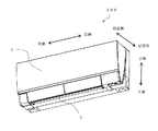
図1は、この実施の形態に係る空気調和機の室内機100の斜視図である。この実施の形態に係る室内機100は、例えば、被空調空間である室内の壁に取り付けられる壁掛け型のものである。室内機100は、前面に前面意匠パネル1を備え、前面の下部に吹出口2を備える。
FIG. 1 is a perspective view of an
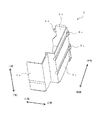
図2は、図1に記載の室内機100の分解斜視図である。室内機100は、背面側筐体3、左側筐体11、右側筐体12および前面側筐体13を含み、これらは、室内機100の筐体を構成する。前面側筐体13のさらに前面側には、意匠部材である前面意匠パネル1が取り付けられる。なお、左側筐体11および右側筐体12は、室内機100の左右側面の意匠部材を構成する。
FIG. 2 is an exploded perspective view of the
室内機100の筐体内には、熱交換器4、熱交換器カバー5、電気品箱6、ドレンパン7、ファン固定部9およびプロペラファン10が収容される。熱交換器4は、その内部を流れる冷媒と周囲空気との熱交換を行うものである。ドレンパン7は、熱交換器4の下側に設置され、室内機100の筐体内で結露して落下した水滴を受けるものである。
A
熱交換器4の上側には、プロペラファン10を固定するファン固定部9が設置される。プロペラファン10は、室内機100の筐体の外側から空気を吸い込み、吸い込んだ空気を熱交換器4に通過させて、熱交換器4を通過した空気を室内機100の筐体の外側に吹き出すように、空気流れを発生させるものである。
A fan fixing part 9 for fixing the
熱交換器カバー5は、熱交換器4の右側に設置され、熱交換器4の右側から飛散した結露水を受けるものである。熱交換器4の右側から飛散した結露水は、熱交換器カバー5に受けられて落下し、熱交換器カバー5の下側に設置されたドレンパン7に導かれる。なお、この実施の形態の例では、熱交換器カバー5が、熱交換器4の右側に設置される例について説明するが、熱交換器4の右側および左側に、熱交換器カバーを設置してあっても良い。
The
図3は、図2に記載の熱交換器カバー5の拡大図である。熱交換器カバー5は、前面カバー板5a、背面カバー板5b、前面カバー板5aと背面カバー板5bとを連結する側面カバー板5cを含む。例えば、この実施の形態では、前面カバー板5aと背面カバー板5bと側面カバー板5cとは一体的に形成される。背面カバー板5bの一端(左側)には2個の位置出し用突起5dが形成され、背面カバー板5bの他端(右側)には2個のネジ止め部5eが形成される。なお、位置出し用突起5dおよびネジ止め部5eの位置および個数は、熱交換器カバー5の大きさ等に応じて、適宜変更することができる。
FIG. 3 is an enlarged view of the
図2に示す電気品箱6は、熱交換器カバー5を挟んで、熱交換器4とは反対側に配置される。電気品箱6は、回路基板等を収容するものである。上下方向調節板8は、吹出口2から吹き出される空気の上下方向の向きを調整するものである。
The
図4は、図1に記載の室内機100の縦断面を概略的に記載した概略図である。プロペラファン10を駆動すると、室内機100の上側から、室内機100の筐体内に空気が吸い込まれる。室内機100の筐体内に吸い込まれた空気は、熱交換器4で熱交換が行われる。熱交換器4で熱交換が行われた空気は、吹出口2から吹き出される。なお、冷房運転を行っている場合には、室内機100に吸い込まれた空気は、熱交換器4で冷却される。また、暖房運転を行っている場合には、室内機100に吸い込まれた空気は、熱交換器4で暖められる。
FIG. 4 is a schematic diagram schematically illustrating a longitudinal section of the
図5は、図2に記載の熱交換器4の右側を拡大した拡大図である。熱交換器4は、その右側に、複数のU字状配管14、複数の補助配管15、複数の接続配管16を有する。U字状配管14は、概略U字形状であり、熱交換器4の右側面から突出している。U字状配管14は、熱交換器4の伝熱管(図示を省略してある)を接続するものである。補助配管15は、U字状配管14よりもさらに右側に延びており、例えば、熱交換器4の前面側の伝熱管と背面側の伝熱管とを接続するものである。なお、以下の説明では、複数のU字状配管14および複数の補助配管15を含む配管群を単に配管群Zともいう。
FIG. 5 is an enlarged view in which the right side of the
接続配管16は、室内機100と室外機(図示を省略してある)とを接続するものである。接続配管16は、熱交換器4の右側面から突出し、U字状配管14および補助配管15よりもさらに右側で下側に向いて曲げられている。接続配管16は、室内機100の熱交換器4と室外機へ向かう外部配管(図示を省略してある)とを接続する。
The
接続配管16の大部分は、接続配管カバー17によって覆われている。接続配管カバー17は、接続配管16とその周囲空気との熱交換を抑制するものである。接続配管カバー17は、好適には、柔軟性(弾性)および断熱性を持つ材質で形成される。
Most of the
図6は、図2に記載の背面側筐体3、熱交換器カバー5およびドレンパン7の右側を拡大した拡大図である。図7は、図6に記載の背面側筐体3に、図5に記載の熱交換器4を設置した状態の斜視図である。なお、図7に記載の熱交換器カバー5は、後述のように、熱交換器4を設置した背面側筐体3に取り付けられる。
FIG. 6 is an enlarged view in which the right side of the back-
図7に示すように、熱交換器4は、背面側筐体3に取り付けられる。熱交換器4の右側で下方に延びる接続配管カバー17は、背面側筐体3に形成された左ガイド壁(第1のガイド壁)18−1と右ガイド壁(第2のガイド壁)18−2との間の接続配管収容部18(図6を参照)に収容される。接続配管収容部18は、例えば、背面側筐体3と一体的に形成される。
As shown in FIG. 7, the
接続配管収容部18の左ガイド壁18−1および右ガイド壁18−2は、接続配管カバー17の左右方向の位置を規制する。すなわち、左ガイド壁18−1と右ガイド壁18−2との間の幅が接続配管カバー17の直径と概略等しくなるように、左ガイド壁18−1および右ガイド壁18−2が形成される。接続配管カバー17は、左ガイド壁18−1と右ガイド壁18−2との間で挟持される。左ガイド壁18−1および右ガイド壁18−2は、図7に示すように、背面側筐体3に取り付けられた熱交換器4の配管群Zよりも、右側に形成される。
The left guide wall 18-1 and the right guide wall 18-2 of the connection
接続配管収容部18は、図6に示すように、接続配管カバー17の背面側を支持する背面ガイド部18−3を有する。背面ガイド部18−3は、接続配管カバー17側に突出した複数個の突起であり、接続配管カバー17の外周形状と概略同形状に形成されている。接続配管収容部18は、熱交換器4の配管群Zよりも右側で、背面側筐体3の上下方向に沿って延びる接続配管カバー17を保持する。
As shown in FIG. 6, the connection
図6に示すように、右ガイド壁18−2よりも熱交換器4側に形成された左ガイド壁18−1には、熱交換器カバー5の位置出し用突起5dが挿入される挿入部19が形成されている。熱交換器カバー5の位置出し用突起5dを左ガイド壁18−1の挿入部19に挿入することによって、熱交換器カバー5と背面側筐体3とが位置決めされる。位置出し用突起5dおよび挿入部19は、熱交換器カバー5と背面側筐体3との位置出しを行う位置出し部を構成する。
As shown in FIG. 6, an insertion portion into which the
熱交換器カバー5と背面側筐体3とが位置決めされると、図7に示す熱交換器カバー5のネジ止め部5eと右ガイド壁18−2に形成されたネジボス20との位置が合わさる。ネジ止め部5eとネジボス20とを利用してネジ止めを行うと、熱交換器カバー5と背面側筐体3とが固定される。ネジ止め部5eおよびネジボス20は、熱交換器カバー5と背面側筐体3との固定を行う固定部を構成する。左ガイド壁18−1よりも熱交換器4から離れた右ガイド壁18−2にネジ止めを行うためのネジボス20を形成してあるので、ネジ止めを容易に行うことができる。この実施の形態では、ネジ止め部5eおよびネジボス20が2箇所形成されているため、2箇所でネジ止めが行われるが、ネジ止め箇所は1箇所であっても良く、3箇所以上であっても良い。
When the
図8は、熱交換器カバー5と背面側筐体3とのネジ止めについて説明する模式図である。図6に示す熱交換器カバー5の位置出し用突起5dを背面側筐体3の挿入部19に挿入すると、熱交換器カバー5と背面側筐体3とが位置決めされて、図8に示すように、ネジ止め部5eとネジボス20との位置が合わさる。ネジ止め部5eとネジボス20との位置が合わさった状態で、固定ネジ21にてネジ止めを行う。
FIG. 8 is a schematic diagram for explaining screwing between the
図9は、図7に記載の熱交換器4、背面側筐体3および熱交換器カバー5を組み立てた状態の横断面を概略的に記載した概略図である。図10は、図9に記載の接続配管収容部18の部分を拡大した拡大図である。図11は、図10に記載の熱交換器カバー5の背面カバー板5bの背面図である。
FIG. 9 is a schematic view schematically illustrating a transverse section in a state where the
図9および図10に示すように、熱交換器カバー5が背面側筐体3に取り付けられると、熱交換器カバー5は、熱交換器4の右側の配管群Zを覆うとともに、接続配管カバー17を背面側に押圧する。熱交換器カバー5は、弾性を有する接続配管カバー17を背面側筐体3に押し付けるので、接続配管カバー17は、熱交換器カバー5と背面側筐体3との間で好適に挟持される。この実施の形態では、左ガイド壁18−1と右ガイド壁18−2との間で挟持されて上下方向に延びる接続配管カバー17の部分を背面側筐体3に押し付けて、接続配管カバー17を背面側筐体3に固定している。なお、熱交換器カバー5は、他の場所で、接続配管カバー17を背面側筐体3に押し付けても良い。
As shown in FIGS. 9 and 10, when the
図10および図11に示すように、熱交換器カバー5の背面カバー板5bの背面側には、背面カバー板5bの背面から突出する位置出し用突起5dおよび押圧用突起5fが形成されている。位置出し用突起5dおよび押圧用突起5fは、接続配管カバー17に当接して、接続配管カバー17を背面側筐体3に押し付ける。位置出し用突起5dは、押圧用突起5fよりも右側に突出しており、上述のように、図7に記載の左ガイド壁18−1の挿入部19に挿入される。
As shown in FIGS. 10 and 11, on the back side of the
図11に示すように、2つの位置出し用突起5dの間には、熱交換器カバー5の左側面から位置出し用突起5dと同じ方向(左側)に突出するガイド部5hが形成されている。ガイド部5hは、突出方向の先端側(左側)が細くなるように形成された先細の形状である。ガイド部5hを図7に記載の左ガイド壁18−1の挿入部19の間の前面側端部(端面)に当接させることによって、熱交換器カバー5と背面側筐体3との位置決めを好適に行うことができる。さらに、熱交換器カバー5を背面側筐体3に取り付ける際に、位置出し用突起5dに作用する応力を軽減することができるので、位置出し用突起5dが変形または損傷するおそれが軽減されている。
As shown in FIG. 11, a guide portion 5h is formed between the two
図10および図11に示すように、背面カバー板5bの背面側に形成された複数の押圧用突起5fは、左右方向に沿った長さが、左ガイド壁18−1と右ガイド壁18−2との間の幅と概略等しくなるように形成されている。このため、左ガイド壁18−1と右ガイド壁18−2との間に、熱交換器カバー5の押圧用突起5fを合わせて、熱交換器カバー5と背面側筐体3との位置決めを行うことができる。
As shown in FIGS. 10 and 11, the plurality of pressing protrusions 5f formed on the back side of the
図12は、ドレンパン7と熱交換器カバー5との位置関係を上側から見た模式図である。図13は、熱交換器4とドレンパン7と熱交換器カバー5との位置関係を左側から見た模式図である。
FIG. 12 is a schematic view of the positional relationship between the
冷房運転時に、熱交換器4で熱交換が行われると、熱交換器4で結露が発生する場合がある。そこで、図13に示すように、熱交換器4の下部には、落下した結露水を受けるためのドレンパン7が設置されている。また、熱交換器4の右側には、熱交換器4の右側に飛散した結露水を受けるための熱交換器カバー5が設置されている。
If heat is exchanged in the
上記のように、熱交換器4の右側では、熱交換器4の側面から配管群Zが突出している。配管群Zが配置された場所では、配管が入り組んで配置されており、ある配管から落下した結露水が、他の配管に当たって、結露水が飛散することがある。たとえば、断面形状が円形の配管の場合には、配管群Zの左右方向に結露水が飛び散りやすい。このため、熱交換器4よりも右側に設置された電気品箱6に、結露水が付着しないように、熱交換器4の配管群Zと電気品箱6との間に熱交換器カバー5が設置される。熱交換器カバー5は、熱交換器4の配管群Zを覆っており、熱交換器4の右側に飛散した結露水を受ける。
As described above, the pipe group Z protrudes from the side surface of the
熱交換器カバー5の前面カバー板5aは、図13に示すように、配管群Zの前面側を覆っている。また、配管群Zの右側および背面側は、図9および図10に示すように、側面カバー板5cと背面カバー板5bと背面側筐体3とによって覆われている。したがって、この実施の形態では、熱交換器カバー5の右側には結露水が飛散しないようになっている。その結果、熱交換器カバー5よりも右側に設置された電気品箱6(図2を参照)には結露水が付着しない。
The
図14は、図13に記載の熱交換器カバー5を左側から見た斜視図である。熱交換器カバー5が受けた結露水は重力によって下側に向かう。ここで、熱交換器カバー5は、熱交換器4の右側に飛散する結露水を確実に受けるように、ドレンパン7よりも大きく形成されている。そこで、熱交換器カバー5の下側は、熱交換器カバー5よりも内側に位置するドレンパン7に結露水が向かうように傾斜された傾斜部5gに形成されている。熱交換器カバー5が受けた結露水は、傾斜部5gを通ってドレンパン7に導かれる。
FIG. 14 is a perspective view of the
上記のように、この実施の形態では、結露水を受ける熱交換器カバー5を背面側筐体3に取り付けるのみで、接続配管カバー17に覆われた接続配管16を背面側筐体3に固定することができる。この実施の形態では、熱交換器カバー5を取り付けることによって、接続配管16が好適に固定されるため、室内機100の筐体内部での接続配管16の捻じれ、変形および損傷等のおそれが軽減されている。
As described above, in this embodiment, the
好適には、接続配管16は、図5に示すように、熱交換器4の右側面から突出し、U字状配管14および補助配管15よりもさらに右側で上側に曲げられ、その後に下側に曲げられる。このように、接続配管16を上側に曲げてから下側に曲げることによって、熱交換器カバー5と背面側筐体3とで接続配管16を挟持する面積を大きくすることができる。すなわち、図7に示すように、接続配管収容部18に収容される接続配管カバー17の長さを長くすることができるので、接続配管収容部18で熱交換器カバー5によって押し付けられる接続配管カバー17の面積を大きくすることができる。その結果、接続配管16を好適に固定することができる。
Preferably, as shown in FIG. 5, the
この発明は、上記の実施の形態に限定されるものではなく、この発明の範囲内で種々に改変することができる。すなわち、上記の実施の形態の構成を適宜改良してもよく、また、少なくとも一部を他の構成に代替させてもよい。さらに、その配置について特に限定のない構成要件は、実施の形態で開示した配置に限らず、その機能を達成できる位置に配置することができる。 The present invention is not limited to the above-described embodiment, and various modifications can be made within the scope of the present invention. That is, the configuration of the above embodiment may be improved as appropriate, or at least a part of the configuration may be replaced with another configuration. Further, the configuration requirements that are not particularly limited with respect to the arrangement are not limited to the arrangement disclosed in the embodiment, and can be arranged at a position where the function can be achieved.
例えば、上記の実施の形態では、接続配管16が熱交換器4の右側に突出した例について説明したが、この発明は、接続配管が熱交換器4の左側に突出した室内機にも適用することができる。
For example, in the above embodiment, the example in which the
また、例えば、接続配管16を熱交換器カバー5で直接的に固定する構成であっても良い。この場合には、接続配管カバー17の少なくとも一部を省略することができる。
Further, for example, the
1 前面意匠パネル、2 吹出口、3 背面側筐体、4 熱交換器、5 熱交換器カバー、5a 前面カバー板、5b 背面カバー板、5c 側面カバー板、5d 位置出し用突起、5e ネジ止め部、5f 押圧用突起、5g 傾斜部、5h ガイド部、6 電気品箱、7 ドレンパン、8 上下方向調節板、9 ファン固定部、10 プロペラファン、11 左側筐体、12 右側筐体、13 前面側筐体、14 U字状配管、15 補助配管、16 接続配管、17 接続配管カバー、18 接続配管収容部、18−1 左ガイド壁、18−2 右ガイド壁、18−3 背面ガイド部、19 挿入部、20 ネジボス、21 固定ネジ、100 室内機、Z 配管群。
DESCRIPTION OF
Claims (4)
熱交換器と、
前記熱交換器が収容された筐体と、
前記熱交換器の左右方向の一方の側から突出し、当該室内機と室外機とを接続する接続配管と、
前記筐体内に配置され、前記熱交換器の前記一方の側に飛散した結露水を受ける熱交換器カバーと、
前記接続配管を覆う接続配管カバーと、を有し、
前記熱交換器カバーは、前記接続配管カバーを前記筐体に押し付けて、前記接続配管を前記筐体に固定しており、
前記熱交換器は、前記一方の側に突出する複数の配管群を含み、
前記接続配管は、前記複数の配管群よりも前記熱交換器から離れた場所で、上側に曲げてから下側に曲げられており、
前記筐体には、前記接続配管カバーのうちの上下方向に沿って延びる部分を収容する接続配管収容部が形成されており、
前記熱交換器カバーは、前記接続配管カバーの前記接続配管収容部に収容された、上側に曲げてから下側に曲げられた部分を前記筐体に押し付けて、前記接続配管を前記筐体に固定していることを特徴とする空気調和機の室内機。 An air conditioner indoor unit,
A heat exchanger,
A housing containing the heat exchanger;
Projecting from one side in the left-right direction of the heat exchanger, a connection pipe connecting the indoor unit and the outdoor unit,
A heat exchanger cover that is disposed within the housing and receives condensed water scattered on the one side of the heat exchanger;
A connection piping cover that covers the connection piping;
The heat exchanger cover presses the connection pipe cover against the casing, and fixes the connection pipe to the casing .
The heat exchanger includes a plurality of piping groups protruding to the one side,
The connecting pipe is bent at the upper side after being bent from the upper side at a place farther from the heat exchanger than the plurality of pipe groups,
The casing is formed with a connecting pipe accommodating portion that accommodates a portion extending along the vertical direction of the connecting pipe cover.
The heat exchanger cover presses a portion of the connection pipe cover, which is accommodated in the connection pipe housing portion, bent upward and then bent downward, against the casing, and connects the connection pipe to the casing. An indoor unit of an air conditioner characterized by being fixed .
前記第2のガイド壁よりも前記熱交換器側に形成された前記第1のガイド壁に、前記筐体と前記熱交換器カバーとの位置出しを行う位置出し部が形成され、
前記第2のガイド壁に、前記筐体と前記熱交換器カバーとの固定を行う固定部が形成されたことを特徴とする請求項1記載の空気調和機の室内機。 The connection pipe housing portion has a first guide wall and a second guide wall that regulate a position in a left-right direction of a portion extending along the vertical direction of the connection pipe cover,
A positioning portion for positioning the housing and the heat exchanger cover is formed on the first guide wall formed on the heat exchanger side with respect to the second guide wall,
Wherein the second guide wall, said housing and the indoor unit of an air conditioner according to claim 1, wherein the fixing portion is formed to perform the fixing of the heat exchanger cover.
Priority Applications (2)
| Application Number | Priority Date | Filing Date | Title |
|---|---|---|---|
| JP2014038690A JP6242245B2 (en) | 2014-02-28 | 2014-02-28 | Air conditioner indoor unit |
| CN201520111118.1U CN204555020U (en) | 2014-02-28 | 2015-02-15 | The indoor set of air conditioner |
Applications Claiming Priority (1)
| Application Number | Priority Date | Filing Date | Title |
|---|---|---|---|
| JP2014038690A JP6242245B2 (en) | 2014-02-28 | 2014-02-28 | Air conditioner indoor unit |
Publications (3)
| Publication Number | Publication Date |
|---|---|
| JP2015161493A JP2015161493A (en) | 2015-09-07 |
| JP2015161493A5 JP2015161493A5 (en) | 2016-07-21 |
| JP6242245B2 true JP6242245B2 (en) | 2017-12-06 |
Family
ID=53830124
Family Applications (1)
| Application Number | Title | Priority Date | Filing Date |
|---|---|---|---|
| JP2014038690A Expired - Fee Related JP6242245B2 (en) | 2014-02-28 | 2014-02-28 | Air conditioner indoor unit |
Country Status (2)
| Country | Link |
|---|---|
| JP (1) | JP6242245B2 (en) |
| CN (1) | CN204555020U (en) |
Families Citing this family (6)
| Publication number | Priority date | Publication date | Assignee | Title |
|---|---|---|---|---|
| CN107796103A (en) * | 2016-08-29 | 2018-03-13 | 珠海格力电器股份有限公司 | Bottom shell assembly and indoor unit with same |
| US20200333038A1 (en) * | 2018-02-09 | 2020-10-22 | Mitsubishi Electric Corporation | Pipe setting structure, and indoor unit of air-conditioning apparatus |
| CN110274304A (en) * | 2018-03-15 | 2019-09-24 | 珠海格力电器股份有限公司 | Indoor unit and air conditioner with same |
| CN109084371A (en) * | 2018-08-16 | 2018-12-25 | Tcl空调器(中山)有限公司 | Wall-mounted air conditioner and its pedestal |
| US11466891B2 (en) * | 2018-12-25 | 2022-10-11 | Gd Midea Air-Conditioning Equipment Co., Ltd. | Air conditioner indoor unit and air conditioner |
| CN209263169U (en) * | 2018-12-25 | 2019-08-16 | 广东美的制冷设备有限公司 | Air conditioner indoor unit and air conditioner |
Family Cites Families (5)
| Publication number | Priority date | Publication date | Assignee | Title |
|---|---|---|---|---|
| JPS5552018U (en) * | 1978-10-03 | 1980-04-07 | ||
| JP3107506B2 (en) * | 1995-08-22 | 2000-11-13 | 東芝キヤリア株式会社 | Indoor unit of air conditioner |
| JP3296163B2 (en) * | 1995-11-09 | 2002-06-24 | 松下電器産業株式会社 | Connection piping fixing device for air conditioner |
| JP3309729B2 (en) * | 1996-09-13 | 2002-07-29 | 三菱電機株式会社 | Wall-mounted indoor unit for air conditioners |
| JP4753708B2 (en) * | 2005-12-21 | 2011-08-24 | 三洋電機株式会社 | Air conditioner |
-
2014
- 2014-02-28 JP JP2014038690A patent/JP6242245B2/en not_active Expired - Fee Related
-
2015
- 2015-02-15 CN CN201520111118.1U patent/CN204555020U/en not_active Expired - Fee Related
Also Published As
| Publication number | Publication date |
|---|---|
| CN204555020U (en) | 2015-08-12 |
| JP2015161493A (en) | 2015-09-07 |
Similar Documents
| Publication | Publication Date | Title |
|---|---|---|
| JP6242245B2 (en) | Air conditioner indoor unit | |
| JP4818935B2 (en) | Air conditioner outdoor unit | |
| EP2806220A1 (en) | Outdoor unit for refrigeration device | |
| WO2018104990A1 (en) | Outdoor unit of air conditioning device | |
| JP6475040B2 (en) | Air conditioner outdoor unit | |
| CN106765593B (en) | Air conditioner indoor unit and air conditioner | |
| JP2015161493A5 (en) | ||
| JP4023505B2 (en) | Air conditioner | |
| WO2016203542A1 (en) | Air conditioner outdoor unit | |
| JPWO2018225189A1 (en) | Cylindrical heat insulating member and refrigeration cycle device | |
| JP5333287B2 (en) | Air conditioner outdoor unit | |
| JP4759445B2 (en) | Piping unit for water supply pump | |
| JP2012207801A (en) | Wall embedded type air conditioning indoor unit | |
| JPWO2016117133A1 (en) | Heat exchanger fixing plate and air conditioner | |
| JP4081681B2 (en) | Indoor unit and air conditioner | |
| JPWO2018078836A1 (en) | Outdoor unit of air conditioner | |
| JP6264264B2 (en) | Embedded ceiling air conditioner | |
| TW201928264A (en) | air conditioner | |
| WO2019021395A1 (en) | Outdoor unit for air conditioner | |
| JP6847739B2 (en) | Indoor unit of air conditioner | |
| JP2002071162A (en) | Air conditioner | |
| JP2007040640A (en) | Heat exchanger mounting structure for air conditioning equipment | |
| JP2016038170A (en) | Indoor equipment of air conditioner | |
| KR20090027356A (en) | Air-conditioner | |
| JP5817694B2 (en) | Outdoor unit |
Legal Events
| Date | Code | Title | Description |
|---|---|---|---|
| A521 | Request for written amendment filed |
Free format text: JAPANESE INTERMEDIATE CODE: A523 Effective date: 20160601 |
|
| A621 | Written request for application examination |
Free format text: JAPANESE INTERMEDIATE CODE: A621 Effective date: 20160601 |
|
| A977 | Report on retrieval |
Free format text: JAPANESE INTERMEDIATE CODE: A971007 Effective date: 20170310 |
|
| A131 | Notification of reasons for refusal |
Free format text: JAPANESE INTERMEDIATE CODE: A131 Effective date: 20170314 |
|
| A521 | Request for written amendment filed |
Free format text: JAPANESE INTERMEDIATE CODE: A523 Effective date: 20170501 |
|
| TRDD | Decision of grant or rejection written | ||
| A01 | Written decision to grant a patent or to grant a registration (utility model) |
Free format text: JAPANESE INTERMEDIATE CODE: A01 Effective date: 20171010 |
|
| A61 | First payment of annual fees (during grant procedure) |
Free format text: JAPANESE INTERMEDIATE CODE: A61 Effective date: 20171107 |
|
| R150 | Certificate of patent or registration of utility model |
Ref document number: 6242245 Country of ref document: JP Free format text: JAPANESE INTERMEDIATE CODE: R150 |
|
| R250 | Receipt of annual fees |
Free format text: JAPANESE INTERMEDIATE CODE: R250 |
|
| LAPS | Cancellation because of no payment of annual fees |