EP4407211A1 - Modularer untersetzungsgetriebe - Google Patents
Modularer untersetzungsgetriebe Download PDFInfo
- Publication number
- EP4407211A1 EP4407211A1 EP24152980.9A EP24152980A EP4407211A1 EP 4407211 A1 EP4407211 A1 EP 4407211A1 EP 24152980 A EP24152980 A EP 24152980A EP 4407211 A1 EP4407211 A1 EP 4407211A1
- Authority
- EP
- European Patent Office
- Prior art keywords
- transmission system
- power transmission
- driven part
- input
- motor
- Prior art date
- Legal status (The legal status is an assumption and is not a legal conclusion. Google has not performed a legal analysis and makes no representation as to the accuracy of the status listed.)
- Pending
Links
Images


Classifications
-
- F—MECHANICAL ENGINEERING; LIGHTING; HEATING; WEAPONS; BLASTING
- F16—ENGINEERING ELEMENTS AND UNITS; GENERAL MEASURES FOR PRODUCING AND MAINTAINING EFFECTIVE FUNCTIONING OF MACHINES OR INSTALLATIONS; THERMAL INSULATION IN GENERAL
- F16H—GEARING
- F16H1/00—Toothed gearings for conveying rotary motion
- F16H1/28—Toothed gearings for conveying rotary motion with gears having orbital motion
-
- F—MECHANICAL ENGINEERING; LIGHTING; HEATING; WEAPONS; BLASTING
- F16—ENGINEERING ELEMENTS AND UNITS; GENERAL MEASURES FOR PRODUCING AND MAINTAINING EFFECTIVE FUNCTIONING OF MACHINES OR INSTALLATIONS; THERMAL INSULATION IN GENERAL
- F16K—VALVES; TAPS; COCKS; ACTUATING-FLOATS; DEVICES FOR VENTING OR AERATING
- F16K31/00—Actuating devices; Operating means; Releasing devices
- F16K31/02—Actuating devices; Operating means; Releasing devices electric; magnetic
- F16K31/04—Actuating devices; Operating means; Releasing devices electric; magnetic using a motor
- F16K31/041—Actuating devices; Operating means; Releasing devices electric; magnetic using a motor for rotating valves
- F16K31/043—Actuating devices; Operating means; Releasing devices electric; magnetic using a motor for rotating valves characterised by mechanical means between the motor and the valve, e.g. lost motion means reducing backlash, clutches, brakes or return means
-
- F—MECHANICAL ENGINEERING; LIGHTING; HEATING; WEAPONS; BLASTING
- F16—ENGINEERING ELEMENTS AND UNITS; GENERAL MEASURES FOR PRODUCING AND MAINTAINING EFFECTIVE FUNCTIONING OF MACHINES OR INSTALLATIONS; THERMAL INSULATION IN GENERAL
- F16H—GEARING
- F16H1/00—Toothed gearings for conveying rotary motion
- F16H1/28—Toothed gearings for conveying rotary motion with gears having orbital motion
- F16H1/36—Toothed gearings for conveying rotary motion with gears having orbital motion with two central gears coupled by intermeshing orbital gears
-
- F—MECHANICAL ENGINEERING; LIGHTING; HEATING; WEAPONS; BLASTING
- F16—ENGINEERING ELEMENTS AND UNITS; GENERAL MEASURES FOR PRODUCING AND MAINTAINING EFFECTIVE FUNCTIONING OF MACHINES OR INSTALLATIONS; THERMAL INSULATION IN GENERAL
- F16K—VALVES; TAPS; COCKS; ACTUATING-FLOATS; DEVICES FOR VENTING OR AERATING
- F16K31/00—Actuating devices; Operating means; Releasing devices
- F16K31/02—Actuating devices; Operating means; Releasing devices electric; magnetic
- F16K31/04—Actuating devices; Operating means; Releasing devices electric; magnetic using a motor
- F16K31/047—Actuating devices; Operating means; Releasing devices electric; magnetic using a motor characterised by mechanical means between the motor and the valve, e.g. lost motion means reducing backlash, clutches, brakes or return means
-
- F—MECHANICAL ENGINEERING; LIGHTING; HEATING; WEAPONS; BLASTING
- F16—ENGINEERING ELEMENTS AND UNITS; GENERAL MEASURES FOR PRODUCING AND MAINTAINING EFFECTIVE FUNCTIONING OF MACHINES OR INSTALLATIONS; THERMAL INSULATION IN GENERAL
- F16D—COUPLINGS FOR TRANSMITTING ROTATION; CLUTCHES; BRAKES
- F16D11/00—Clutches in which the members have interengaging parts
- F16D11/08—Clutches in which the members have interengaging parts actuated by moving a non-rotating part axially
- F16D11/10—Clutches in which the members have interengaging parts actuated by moving a non-rotating part axially with clutching members movable only axially
-
- F—MECHANICAL ENGINEERING; LIGHTING; HEATING; WEAPONS; BLASTING
- F16—ENGINEERING ELEMENTS AND UNITS; GENERAL MEASURES FOR PRODUCING AND MAINTAINING EFFECTIVE FUNCTIONING OF MACHINES OR INSTALLATIONS; THERMAL INSULATION IN GENERAL
- F16D—COUPLINGS FOR TRANSMITTING ROTATION; CLUTCHES; BRAKES
- F16D11/00—Clutches in which the members have interengaging parts
- F16D11/14—Clutches in which the members have interengaging parts with clutching members movable only axially
-
- F—MECHANICAL ENGINEERING; LIGHTING; HEATING; WEAPONS; BLASTING
- F16—ENGINEERING ELEMENTS AND UNITS; GENERAL MEASURES FOR PRODUCING AND MAINTAINING EFFECTIVE FUNCTIONING OF MACHINES OR INSTALLATIONS; THERMAL INSULATION IN GENERAL
- F16H—GEARING
- F16H1/00—Toothed gearings for conveying rotary motion
- F16H1/02—Toothed gearings for conveying rotary motion without gears having orbital motion
- F16H1/20—Toothed gearings for conveying rotary motion without gears having orbital motion involving more than two intermeshing members
-
- F—MECHANICAL ENGINEERING; LIGHTING; HEATING; WEAPONS; BLASTING
- F16—ENGINEERING ELEMENTS AND UNITS; GENERAL MEASURES FOR PRODUCING AND MAINTAINING EFFECTIVE FUNCTIONING OF MACHINES OR INSTALLATIONS; THERMAL INSULATION IN GENERAL
- F16H—GEARING
- F16H1/00—Toothed gearings for conveying rotary motion
- F16H1/28—Toothed gearings for conveying rotary motion with gears having orbital motion
- F16H1/32—Toothed gearings for conveying rotary motion with gears having orbital motion in which the central axis of the gearing lies inside the periphery of an orbital gear
-
- F—MECHANICAL ENGINEERING; LIGHTING; HEATING; WEAPONS; BLASTING
- F16—ENGINEERING ELEMENTS AND UNITS; GENERAL MEASURES FOR PRODUCING AND MAINTAINING EFFECTIVE FUNCTIONING OF MACHINES OR INSTALLATIONS; THERMAL INSULATION IN GENERAL
- F16H—GEARING
- F16H57/00—General details of gearing
- F16H57/02—Gearboxes; Mounting gearing therein
- F16H57/023—Mounting or installation of gears or shafts in the gearboxes, e.g. methods or means for assembly
-
- F—MECHANICAL ENGINEERING; LIGHTING; HEATING; WEAPONS; BLASTING
- F16—ENGINEERING ELEMENTS AND UNITS; GENERAL MEASURES FOR PRODUCING AND MAINTAINING EFFECTIVE FUNCTIONING OF MACHINES OR INSTALLATIONS; THERMAL INSULATION IN GENERAL
- F16K—VALVES; TAPS; COCKS; ACTUATING-FLOATS; DEVICES FOR VENTING OR AERATING
- F16K31/00—Actuating devices; Operating means; Releasing devices
- F16K31/02—Actuating devices; Operating means; Releasing devices electric; magnetic
- F16K31/04—Actuating devices; Operating means; Releasing devices electric; magnetic using a motor
- F16K31/05—Actuating devices; Operating means; Releasing devices electric; magnetic using a motor specially adapted for operating hand-operated valves or for combined motor and hand operation
-
- F—MECHANICAL ENGINEERING; LIGHTING; HEATING; WEAPONS; BLASTING
- F16—ENGINEERING ELEMENTS AND UNITS; GENERAL MEASURES FOR PRODUCING AND MAINTAINING EFFECTIVE FUNCTIONING OF MACHINES OR INSTALLATIONS; THERMAL INSULATION IN GENERAL
- F16K—VALVES; TAPS; COCKS; ACTUATING-FLOATS; DEVICES FOR VENTING OR AERATING
- F16K31/00—Actuating devices; Operating means; Releasing devices
- F16K31/44—Mechanical actuating means
- F16K31/53—Mechanical actuating means with toothed gearing
-
- H—ELECTRICITY
- H02—GENERATION; CONVERSION OR DISTRIBUTION OF ELECTRIC POWER
- H02K—DYNAMO-ELECTRIC MACHINES
- H02K7/00—Arrangements for handling mechanical energy structurally associated with dynamo-electric machines, e.g. structural association with mechanical driving motors or auxiliary dynamo-electric machines
- H02K7/003—Couplings; Details of shafts
-
- H—ELECTRICITY
- H02—GENERATION; CONVERSION OR DISTRIBUTION OF ELECTRIC POWER
- H02K—DYNAMO-ELECTRIC MACHINES
- H02K7/00—Arrangements for handling mechanical energy structurally associated with dynamo-electric machines, e.g. structural association with mechanical driving motors or auxiliary dynamo-electric machines
- H02K7/10—Structural association with clutches, brakes, gears, pulleys or mechanical starters
- H02K7/116—Structural association with clutches, brakes, gears, pulleys or mechanical starters with gears
-
- F—MECHANICAL ENGINEERING; LIGHTING; HEATING; WEAPONS; BLASTING
- F16—ENGINEERING ELEMENTS AND UNITS; GENERAL MEASURES FOR PRODUCING AND MAINTAINING EFFECTIVE FUNCTIONING OF MACHINES OR INSTALLATIONS; THERMAL INSULATION IN GENERAL
- F16H—GEARING
- F16H57/00—General details of gearing
- F16H57/02—Gearboxes; Mounting gearing therein
- F16H2057/02034—Gearboxes combined or connected with electric machines
-
- F—MECHANICAL ENGINEERING; LIGHTING; HEATING; WEAPONS; BLASTING
- F16—ENGINEERING ELEMENTS AND UNITS; GENERAL MEASURES FOR PRODUCING AND MAINTAINING EFFECTIVE FUNCTIONING OF MACHINES OR INSTALLATIONS; THERMAL INSULATION IN GENERAL
- F16H—GEARING
- F16H2200/00—Transmissions for multiple ratios
- F16H2200/20—Transmissions using gears with orbital motion
- F16H2200/2002—Transmissions using gears with orbital motion characterised by the number of sets of orbital gears
- F16H2200/2007—Transmissions using gears with orbital motion characterised by the number of sets of orbital gears with two sets of orbital gears
Definitions
- the invention relates to a speed reducer for a mechanical power transmission system implemented in particular in an electric actuator, or servomotor, for industrial valves or louvers.
- Industrial valves and louvers are used in industries in which fluids (liquids or gases) circulate in pipes, and the circulation of the fluid is controlled by a movable member interposed (obturator) in the conduit and whose position must be controlled or even slaved to instantaneous control (variable over time, including very quickly) to cope with the force imposed by the fluid on the mobile member.
- a movable member interposed (obturator) in the conduit whose position must be controlled or even slaved to instantaneous control (variable over time, including very quickly) to cope with the force imposed by the fluid on the mobile member.
- the control of the valve or vent is often implemented by a mechanical member of the wheel and worm screw type, the wheel being installed on a control member of the valve or vent (shafts transmitting the power) and the worm being connected to the axis of a rotary electric motor.
- the endless screw and the associated wheel make it possible to provide for the irreversibility of the power transmission, since their design, by adapting the screw pitch, makes it possible to guarantee that the valve or louver will not return force to the motor.
- a reduction gear introducing a speed ratio to be chosen depending on the circumstances (particularly depending on the valve on which the servomotor is installed) can be introduced between the electric motor and the endless screw.
- a sensor tracks the position of the shutter member, to know to what extent, at each moment, it blocks the flow, and redefine the control according to this information.
- Such a servomotor can be mounted on a valve in the energy sector, particularly in nuclear power plants, or in the water sector, in the industrial sector such as cement factories, or even in the oil industry sector. and gas. Other industries also use such systems.
- the invention applies to multi-turn, or quarter-turn or more generally fraction-of-turn servomotors and to other types of electric actuators.
- the servomotor can be used in different contexts.
- This reduction gear can in particular be an epicyclic gear train (reducer with three shafts, two planetary gears and satellites) of which a sun gear is coupled directly to the endless screw, a crown gear is coupled to the motor, and a planet carrier is embedded in the casing of the servomotor.
- a mechanical power transmission system for controlling a valve or a louver, the transmission system comprising an actuating mechanism for a shaft of the valve or louver, the actuation mechanism having a first and a second power input, the system comprising a rotary motor and a rotating manual actuator coupled respectively to the first and second power inputs, a rod release mechanism exerting a thrust to disengage said motor with respect to the first power input.
- the clutch mechanism is remarkable in that it comprises a driving part and a driven part together constituting a clutch on an axis, the driven part having a toothed ring and a driven part imprint of the clutch, and being coupled to the first input by said toothed ring gear, at least one satellite pinion of the power transmission system and a central bore for coupling (complementary to the first input), for example a splined bore, said driven part having a central bore (for example a complementary splined bore of said first inlet), the rod, to carry out a disengagement, passing through the two central bores and pushing a hub of the driving part.
- the driven part, the sun gear and the satellite gear(s) can be inverted and interchanged so as to modify the speed ratio between the rotary motor and the actuation mechanism. It is easy for the through bore to be in the center of a first part which is a driving part such as a planet carrier or a solar pinion, but which also carries an imprint of a second driven part of a dog to be used as a substitute when operators wish to carry out the inversion.
- a driving part such as a planet carrier or a solar pinion
- first driven dog part can carry the shapes of a second drive part, in addition to its shape of the driven dog part, and therefore also have a form of carrier.
- satellites equipped with its satellites
- solar pinion to be used as a substitute when operators wish to carry out the inversion.
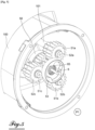
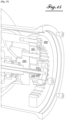
- FIG. 1 In figure 1 a general view of an ESM servomotor assembly according to the invention is shown, protected by and inserted in a main casing 100 - the ESM servomotor assembly comprising in particular a central endless screw in the mechanism and placed in this main casing 100 - and a second casing, the motor casing 200, on the right of the figure.
- the ESM servomotor assembly comprises a steering wheel 1, an electric motor 2 whose rotor is referenced 21, a worm and associated wheel assembly, from which we see the wheel 3 (rear in the view) and the worm 4 ( in the plane of the figure), the respective ends of which are depending on the circumstances coupled one, the left end in the figure, to the steering wheel 1, occasionally and the other, the right end in the figure, to the engine 2, in the majority of life situations of the ESM servomotor.
- the ESM servomotor assembly also includes a disengagement system 5 between the motor 2 and the endless screw 4 and a mechanical reduction and control assembly called manual control 10, placed between the flywheel 1 and the endless screw, pushing under the action of a human operator himself acting by pushing on the steering wheel 1 in the direction of the engine 2 a through clutch actuator 6.
- the through clutch actuator 6 has the structure of a translational rod inserted and moving in a longitudinal bore of the worm screw 4, at the end of which it is placed to open the clutch system 5 when the operator human pushes on the steering wheel 1 to engage the manual actuation by the steering wheel, which is much easier to carry out if the motor 2 is decoupled from the endless screw 4.
- Wheel 3 is placed on a shaft of the servomotor which is coupled with the shaft of an industrial valve or valve (not shown).
- the orientation of the servomotor assembly ESM seen as the axis common to the electric motor 2 and the steering wheel 1 as well as the endless screw 4 can be either horizontal or vertical.
- the flywheel 1 and the electric motor 2 are placed coaxially with the endless screw 4 and coupled or coupleable with respectively one and the other of its two ends.
- the declutching system 5 is able to decouple the electric motor 2 from the first end (on the right in the figure) of the endless screw 4 or to couple them and the manual control 10 is able to carry out a gear change of speeds between the flywheel 1 and the endless screw 4 or to decouple these two elements, and reversibly couple them again, on the side of the second end of the endless screw (on the left in the figure).
- the through actuator 6 is a purely mechanical system, in the embodiment presented, configured to transmit a change of configuration from the declutching system 5 to the manual control 10 or vice versa from the manual control 10 to the declutching system 5.
- L The through actuator does not transmit mechanical power, but it allows switching from one configuration of the declutching system 5 to another or from one configuration of the manual control 10 to another, respectively under the control of a signal ( a thrust) coming from the other end of the endless screw 4.
- the through actuator 6 is in particular constructed on the basis of an actuating rod introduced into a through bore of the endless screw 4.
- the rod actuation opens at both ends of the endless screw 4 and it transmits, by its axial translation (that is to say longitudinal) towards the left or its axial translation towards the right, a command (a thrust) which causes a switching to the either end of the endless screw 4.
- the electric motor 2 When the electric motor 2, initially stopped and decoupled from the endless screw 4, begins to move under the action of a motor command, often received by a means of remote communication, the electric motor 2 is coupled to the endless screw 4 by the disengagement system 5 and a motor connection spring 62.
- the motor connection spring 62 makes it possible to release a blocking element (a leaf spring which will be presented later), so that the coupling is produced, due to the start of the rotation.
- the spring pushes the actuating rod of the through actuator 6 towards the power transmission module 10, and causes, via the end of this rod, the decoupling of the flywheel 1 from the endless screw 4.
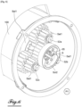
- FIG. 2 In figure 2 the detailed elements of the declutching system 5 have been shown.
- the through actuator 6 On the left of the figure is the through actuator 6 with the actuating rod movable in longitudinal translation from left to right and from right to left.
- the motor connection spring 62 Opposite the actuating rod is the motor connection spring 62 which presses on a sliding shaft 63.
- the sliding shaft 63 slides in a blind bore of the rotor of the electric motor 21, at the bottom of which is placed the motor connection spring 62.
- the sliding shaft 63 has at its end opposite the motor connection spring 62 a form for receiving the end of the actuating rod.
- the motor connection spring 62 Conversely when the sliding shaft 63 is moved towards the left, the motor connection spring 62 is decompressed (this is generally what causes the shaft to move to the left) and the actuating rod moves to the left, by pushing the shaft sliding 63.
- the disengagement system 5 also includes a slider 59 mounted on the shaft 63, and which can carry the receiving shape of the end of the actuating rod.
- the stem actuation pushes the player 59 towards the electric motor, and causes the compression of the spring connecting to the motor 62 by the player 59.
- the player 59 and the shaft 63 are a single part.
- the player in any case constitutes a driving part of the clutch, and carries in its middle, that is to say in its hub, a space through which the actuating rod can open the clutch, by moving the driving part aside. of the piece being conducted.
- the hub can be shaft 63.
- the rod of the through clutch actuator 6 passes through two sun gears placed coaxially with each other and comprising a central bore through each. Given their positions with respect to the motor, they are subsequently called input pinion and output pinion, because they are the input and output of a reduction gear made up of several pinions.
- the output pinion is referenced 50 and the input pinion is referenced 53.
- the gearbox is modular, meaning that the pinions can be moved or replaced or exchanged, to obtain a custom reduction ratio.
- the modular gearbox transmits, when the clutch is closed, the torque of the electric motor, on the right of the figure towards the endless screw actuating the wheel then the servomotor shaft, the valve shaft and the valve, and the torque is first applied to the input gear 53, before reaching the output gear 50.
- the transmission of torque takes place between the input pinion 53 and the output pinion 50 via, in the conformation shown in figure 2 of the modular reducer, of satellites 51a and 51b, a third satellite 51c not being visible in the figure, these three satellites being stepped, so as to mesh with one and the other of the two sun pinions, whose toothed rings have different diameters.
- These three satellites are placed around the input pinion 53 and the output pinion 50 in a regular arrangement in an equilateral triangle.
- the three satellite gears 51a to 51c are each fixed to the main casing 100 by screws 52a to 52c (visible in figure 5 ) passing through a respective satellite gear and fixing it to a boss 101 of the casing.
- the fixing screws are parallel to the axis of the worm screw, and constitute the axis of rotation of the satellite gears, parallel to the axis of rotation of the input and output gears, which are, as already mentioned, solar gears.
- the input pinion 53 and the output pinion 50 rest on each other longitudinally via a needle thrust bearing 56.
- This needle thrust bearing 56 has a role of absorbing axial force. It is placed between a transverse face of one of the two pinions and a transverse face of the other of the two pinions.
- the torque is transmitted from the electric motor via the rotor 21 to the shaft 63, to the slider 59 then to the input pinion 53.
- the slider 59 is, in the position P1 shown in figure 2 , clutched to the input pinion 53, which has a dog shape (this is the driven part) on one of its transverse faces, complementary to the dog shape carried by the transverse face of the slider (this is of the leading part).
- the torque is transmitted from the input pinion 53 to a first section of the satellite gears which all three mesh with it, then from the satellite gears, through a second section of the satellite gears, towards the output pinion 50 which meshes with the three pinions satellites.
- This meshing was made possible, naturally, by a specific choice of the diameter of the two sections of satellite gears, compatible with the diameters of the two planetary gears.
- the output sun pinion 50 has a section which carries the form of driven dog part (which is not used as long as the pinion remains in the output position) and a section which carries teeth of pinions on the periphery (a ring gear) to mesh with the satellites. It also carries, in its center, shapes for its embedding on the end of the endless screw, in this case grooves on the surface of a through bore which is engaged on the end of the endless screw, which constitutes a complementary splined shaft.
- the input sun pinion 53 has a section which carries pinion teeth on the periphery (a ring gear) to mesh with the satellites and a section which carries the shape of a driven dog piece. It also carries, in its center, shapes for its possible embedding on the end of the endless screw, in this case grooves on the surface of a through bore which could be engaged on the end of the endless screw. end, in the hypothesis of a reconfiguration of the gearbox, with inversion of the output solar pinion 50 and the input solar pinion 53.
- the output pinion can be placed at the input, in which case its dog driven part shape will be used, but its splined bore will not be, and vice versa.
- the input pinion can be placed at the output, in which case its shape of driven dog part will not be used, and its fluted bore will be.
- the satellite gears are turned over and screwed in the same way as before.
- FIG. 3 In Figure 3 we represented the system of figure 2 , without reduction between the electric motor and the endless screw. Thus, are visible on the left of the figure, near the through actuator 6, a fixing boss 101 which is not used, because the satellite gears have not been introduced.
- the shaft 63 and the slider 59 which is connected to an extension 8 coupled by splines to the endless screw 4.
- the endless screw has grooves on the circumference of the its end, and the extension 8 includes a grooved bore complementary to these grooves.
- the figure also allows us to see the leaf spring 7 which is screwed by screws 7a to the casing of the electric motor 200, and ensures the role of locking the clutch in the open position, with the engine off, as will be commented on later.
- the output pinion 50 shown in figure 2 is preserved and directly coupled in rotation, in this configuration, with the input pinion 53 also preserved, by a coupling means placed on the axis of rotation and embedded with one and with the other, the satellite gears being deleted.
- the slider 59 is connected to the input pinion 53, which defines the position P1 of the clutch system of the electric motor: the electric motor is coupled to the endless screw.
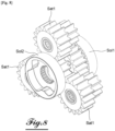
- FIG. 5 shows the modular gearbox of the clutch release system 5 in a three-quarter view from another angle, from the engine space, and looking into the main housing 100 (the worm housing). And this time the player is not shown, to avoid overloading the image, which allows us to visualize the interior of the input pinion 53, which bears the form of a dog driven part.
- We also see the end of the actuating rod which protrudes from the center of the input pinion 53, and which is held by an axial retaining circlip 65.
- the actuating rod of the through clutch actuator 6 passes through the input pinion and the output pinion, through their bores, until they come into contact with the driving part of the clutch (not shown in the figure), which has a surface to be pushed by the rod.
- FIG. 6 There Figure 6 is a view similar to the view of the figure 5 , with nevertheless a different form of engagement of the input pinion 53 (the driven part).
- the input pinion 53 the driven part
- the set of gears is not the same.
- the satellite gears Sat1 are stepped gears having two toothed rings arranged successively on their axis, one of which with a large diameter meshing with the (solar) pinion Sol1 (placed at the output), and a small diameter meshing with the solar pinion Sol2 (pinion placed at the input), whereas it was the opposite in the assembly of the figure 5 .
- the diameters of the toothed wheels of the input and output pinions are of course adapted to mesh with the corresponding sections of the satellites: the toothed ring of Sol2 is larger than the toothed ring of Sol1, whereas it was the opposite in figure 5 .
- FIG. 7 There figure 7 represents the assembly of the Figure 6 in section view. It appears in particular that the meshing diameter of the pinion Sol1 is smaller than the meshing diameter of the pinion Sol2, as has just been said.
- FIG. 8 is a three-quarter view where only the gables are represented (a dog shape with three tenons and three mortises is represented, this point being independent of the other characteristics).
- the clutch forms of Sol1 and Sol2 are identical, so that either can be used in cooperation with the player which was said to form the other part of the clutch, i.e. i.e. the leading piece.
- the dog shape is surrounded by a circumference whose external diameter is devoid of teeth, and which has the same external diameter as the top of the teeth, which makes it possible to provide a longitudinal stop to the teeth of the satellites.
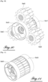
- FIG. 10 There Figure 10 shown from the same angle as the figures 8 And 9 an assembly with the Sol1 pinion, a new Sol3 pinion and satellites different from the previous ones, referenced Sat2. This assembly makes it possible to obtain a reduction ratio different from the two previous assemblies, in the context of the modularity of the reducer.
- FIG. 11 shows an assembly without satellites with a direct transmission between two examples of the Sol 3 pinion which are connected to each other by a central key (not visible).
- a central key not visible
- the toothed wheels of these two pinions are not used, the torque is instead transmitted by the key which is inserted into the internal grooved bores of these two examples of the Sol 3 pinion.
- FIG. 12 In Figure 12 we have shown the structure of a Sol solar pinion which can be placed either in front of the player to engage it by interconnection and couple the motor to the endless screw in a reversible manner by serving as an input pinion to the reducer , or by engagement of splines 505 on the endless screw, so as to serve as the output pinion of the reducer.
- the Sol sun pinion comprises, externally, two sections along the axis: a section with teeth 501 forming the crown, and a smooth exterior section, described here as a clutch section 502.
- the interconnection section 502 includes a cavity 503 open for access by longitudinal translation, the side walls delimiting the cavity 503 being parallel to the longitudinal axis of the solar pinion Sol to allow engagement of the driving part.
- the cavity 503 has a bottom which is a flat wall 504 perpendicular to the longitudinal axis of the pinion.
- a large cylindrical bore with general geometry of revolution and fluted 505 is present in the sun pinion Sol.
- This grooved bore 505 itself has a bottom which is pierced in its center with a bore of smaller diameter passing through the toothed wheel 501 to its face opposite the cavity 503, and opening out at the center of the teeth 501.
- This bore through the narrower one is used for the passage of the actuating rod.
- the splines on the larger bore are used to engage complementary splines on the worm, in mounting configurations where this pinion is not used for interconnection, but serves as the output pinion of the reducer.
- the cavity 503 is made up of three mortises 506 separated by large tenons 507, but another configuration is possible, to constitute the driven part of the clutch.
- the player 59 which is a dog driving part.
- the player 59 comprises, along the longitudinal axis, a section of large diameter, at the rear in the figure and a narrower section with complex shapes, at the front in the figure.
- the slider 59 includes a grooved through bore 590. It is used to engage the sliding shaft 63, which has complementary grooves on its exterior surface. Another solution can nevertheless be implemented, this point not being essential.
- the actuating rod is able to push the player 59 by resting in its center, either because the sliding shaft constitutes a support for the player (for example due to a key), or because the player and the shaft are in one piece as shown in figure 2 .
- FIG. 14 shows the second position P2 of the declutching system 5.
- the actuating rod has progressed towards the right and its end is more inserted than previously towards the shaft 63.
- the progression of the actuating rod is accompanied by a translation of the player 59 in the direction of the electric motor, and the compression of the spring connecting to the motor 62.
- the leaf spring 7 has, during the time of the translation of the player 59, been moved outwards, radially, by the rear section thereof which has an essentially conical circumference followed by a shoulder, and the blade spring having first been tense, then having passed the shoulder and extends relaxed, rests at the end of this movement on the shoulder which prevents a backward movement of the player 59 despite the pressure applied to it by the connection spring of the motor 62.
- the leaf spring 7 has, during the time of the translation of the player 59, been moved outwards, radially, by the rear section thereof which has an essentially conical circumference followed by a shoulder, and the blade spring having first been tense, then having passed the shoulder and extends relaxed, rests at the end of this movement on the shoulder which prevents a backward movement of the player 59 despite the pressure applied to it by the connection spring of the motor 62.
- the player 59 is no longer coupled to the solar Sol2, because the latter did not follow the translation movement (it is a clutch opening), and is therefore now separated from the player 59.
- the actuating rod translates without friction in the bores of the input pinion and the output pinion of the reducer.
- the slider 59 pushes the actuating rod also to the left so that it is less pressed towards the shaft 63.
- the actuating rod therefore progresses in the manual control at the opposite end of the endless screw, and depending on the mounting thereof can in particular decouple the flywheel from the end of the endless screw, to prevent the motor from rotating the flywheel, which is dangerous for operators .
- the engagement of the player 59 with the solar Sol2 is done by introducing the tenons of the player into the mortises of the solar pinion Sol2.
- the grooves in the solar bore are only used when the solar concerned is placed at the outlet of the reducer, mounted on the endless screw. Conversely, when the sun pinion faces the slider 59, the grooved bore is not used.
- the modular gearbox allows the easy installation of different speed ratios between the electric motor and the worm, depending on the valve which must be equipped.
- FIG.15 presents a second embodiment of the reducer. Known elements are not commented or numbered, to lighten the text and drawing.
- this sun pinion is replaced by a planet carrier 250 and this planet carrier has satellites 251 which mesh with a crown 252 fixed to the casing, as well as with the driven part of the clutch.
- the planet carrier carries a form of driven dog part, not used in the configuration of the figure, but which can be used by swapping its position with that of the driven dog part 253 placed opposite the dog driving part (not shown) in the configuration of the figure.
- This permutation based on the presence of identical grooved bores in the axial position on parts 253 and 250, and on the presence also of identical driven shape of clutch on the two parts, makes it possible to benefit from two different speed ratios: the satellites are placed again, by a longitudinal arrangement, to mesh with the ring gear, even though they are mounted on a planet carrier which faces in the opposite direction in the new configuration.
Landscapes
- Engineering & Computer Science (AREA)
- General Engineering & Computer Science (AREA)
- Mechanical Engineering (AREA)
- Power Engineering (AREA)
- Gear Transmission (AREA)
- Connection Of Motors, Electrical Generators, Mechanical Devices, And The Like (AREA)
- Mechanical Operated Clutches (AREA)
- Mechanically-Actuated Valves (AREA)
Applications Claiming Priority (1)
| Application Number | Priority Date | Filing Date | Title |
|---|---|---|---|
| FR2300660A FR3145200B1 (fr) | 2023-01-24 | 2023-01-24 | Réducteur modulaire |
Publications (1)
| Publication Number | Publication Date |
|---|---|
| EP4407211A1 true EP4407211A1 (de) | 2024-07-31 |
Family
ID=85726846
Family Applications (1)
| Application Number | Title | Priority Date | Filing Date |
|---|---|---|---|
| EP24152980.9A Pending EP4407211A1 (de) | 2023-01-24 | 2024-01-19 | Modularer untersetzungsgetriebe |
Country Status (5)
| Country | Link |
|---|---|
| US (1) | US12560256B2 (de) |
| EP (1) | EP4407211A1 (de) |
| KR (1) | KR20240117063A (de) |
| CN (1) | CN118423489A (de) |
| FR (1) | FR3145200B1 (de) |
Families Citing this family (3)
| Publication number | Priority date | Publication date | Assignee | Title |
|---|---|---|---|---|
| FR3145200B1 (fr) | 2023-01-24 | 2025-01-10 | Bernard Controls | Réducteur modulaire |
| CN119858765B (zh) * | 2025-01-03 | 2025-09-26 | 中国核电工程有限公司 | 一种转运装置以及放射性废物处理系统 |
| CN119802269B (zh) * | 2025-03-13 | 2025-07-01 | 特技阀门集团有限公司 | 一种深海球阀 |
Citations (3)
| Publication number | Priority date | Publication date | Assignee | Title |
|---|---|---|---|---|
| US10024449B2 (en) * | 2015-10-23 | 2018-07-17 | Azbil Corporation | Planetary gear torque limiting structure for a regulating valve |
| US20180298988A1 (en) * | 2017-04-18 | 2018-10-18 | Flowinn (Shanghai) Industrial Co., Ltd. | Speed adjustable returning apparatus for electric actuator |
| FR3145200A1 (fr) | 2023-01-24 | 2024-07-26 | Bernard Controls | Réducteur modulaire |
Family Cites Families (8)
| Publication number | Priority date | Publication date | Assignee | Title |
|---|---|---|---|---|
| US4616528A (en) * | 1982-05-03 | 1986-10-14 | Vapor Corporation | Valve actuator with continuous manual override |
| US4669578A (en) * | 1986-03-13 | 1987-06-02 | Rikuo Fukamachi | Motor driven valve |
| US4896562A (en) * | 1988-03-24 | 1990-01-30 | Limitorque Corporation | Valve actuator differential worm planetary gear drive |
| US5588637A (en) * | 1995-05-30 | 1996-12-31 | Robert L. Carsten | Auxiliary automatic valve shut-off system |
| US7264017B2 (en) * | 2005-05-12 | 2007-09-04 | Honeywell International, Inc. | Dual-actuator aircraft environmental control system valve |
| US8342478B1 (en) * | 2008-06-16 | 2013-01-01 | Tri-Tec Manufacturing, LLC | Valve actuator assembly and methods of using the same |
| US8690119B2 (en) * | 2011-06-16 | 2014-04-08 | Big Horn Valve, Inc. | Leak-free reciprocating stemmed valve |
| US10024499B2 (en) | 2016-12-21 | 2018-07-17 | Chevron U.S.A. Inc. | Method and system for controlling slugging in a fluid processing system |
-
2023
- 2023-01-24 FR FR2300660A patent/FR3145200B1/fr active Active
-
2024
- 2024-01-19 EP EP24152980.9A patent/EP4407211A1/de active Pending
- 2024-01-23 US US18/420,082 patent/US12560256B2/en active Active
- 2024-01-24 CN CN202410101721.5A patent/CN118423489A/zh active Pending
- 2024-01-24 KR KR1020240010760A patent/KR20240117063A/ko active Pending
Patent Citations (3)
| Publication number | Priority date | Publication date | Assignee | Title |
|---|---|---|---|---|
| US10024449B2 (en) * | 2015-10-23 | 2018-07-17 | Azbil Corporation | Planetary gear torque limiting structure for a regulating valve |
| US20180298988A1 (en) * | 2017-04-18 | 2018-10-18 | Flowinn (Shanghai) Industrial Co., Ltd. | Speed adjustable returning apparatus for electric actuator |
| FR3145200A1 (fr) | 2023-01-24 | 2024-07-26 | Bernard Controls | Réducteur modulaire |
Non-Patent Citations (2)
| Title |
|---|
| ANONYMOUS: "Konstruktionszeichnung des Stellantriebs SA", AUMA, EDITION 1.21, AUMA RIESTER GMBH & CO. KG, 19 November 2008 (2008-11-19), pages 1 - 2, XP093256108 |
| BURKAT STEFAN: "Abdruck eines Website-Auszugs des Unternehmens", STEFAN BURKART INGENIEURBÜRO FÜR GETRIEBETECHNIK, 1 August 2018 (2018-08-01), pages 1 - 3, XP093255874, Retrieved from the Internet <URL:https://web.archive.org/web/20180831033523/https://ingbueroburkart.de/sterngetriebe.html> |
Also Published As
| Publication number | Publication date |
|---|---|
| CN118423489A (zh) | 2024-08-02 |
| US12560256B2 (en) | 2026-02-24 |
| KR20240117063A (ko) | 2024-07-31 |
| US20240247732A1 (en) | 2024-07-25 |
| FR3145200A1 (fr) | 2024-07-26 |
| FR3145200B1 (fr) | 2025-01-10 |
Similar Documents
| Publication | Publication Date | Title |
|---|---|---|
| EP4407211A1 (de) | Modularer untersetzungsgetriebe | |
| EP0449739B1 (de) | Angetriebene Schalteinrichtung zum Schalten der Übersetzung eines Getriebes, insbesondere für Kraftfahrzeuge | |
| FR2805587A1 (fr) | Dispositif de transmission automatise a engrenages, en particulier pour vehicule automobile | |
| FR2838169A1 (fr) | Systeme de debrayage pour un mecanisme a deux embrayages pour vehicule automobile. | |
| FR3029874A1 (fr) | Actionneur electrique pour levier de frein de parking au sein d'un frein a tambour | |
| WO2014106714A1 (fr) | Boîte de vitesses pour engin automoteur, tel que tondeuse à gazon | |
| EP0490730A1 (de) | Angetriebene Schalteinrichtung zum Schalten der Übersetzung eines Getriebes, insbesondere für Kraftfahrzeuge | |
| WO1999056040A1 (fr) | Actionneur electromecanique pour boite de vitesses mecanique | |
| FR2774447A1 (fr) | Vehicule equipe d'un dispositif de manoeuvre automatisee d'une boite a vitesses | |
| EP3388712B1 (de) | Planetengetriebe, insbesondere für ein servomotorensystem, und servomotorensystem, das dieses planetengetriebe nutzt | |
| EP4419813B1 (de) | Mechanisches leistungsübertragungsmodul | |
| FR2783030A1 (fr) | Dispositif pour lier une piece de sortie susceptible d'etre entrainee en rotation et en translation d'une installation d'actionnement d'un arbre de commutation | |
| EP2159439B1 (de) | Reibungsvorrichtung für Momentübertragung | |
| EP1538051B1 (de) | Notbetätigungseinrichtung für eine elektromechanische Betriebsbremse | |
| EP2141390A1 (de) | Geschwindigkeitswechselschalter, der in der zentralen Position und den Extrempositionen blockiert werden kann | |
| WO2024115852A1 (fr) | Chaine cinématique irréversible et à rendement élevé, de préférence pour robinet | |
| FR2933465A1 (fr) | Actionneur de passage de vitesses avec des moyens de progressivite disposes entre deux etages de reduction intermediaires | |
| FR2894640A1 (fr) | Boite de vitesse pour chaine de traction electrique basse tension | |
| WO2008113954A2 (fr) | Actionneur electromecanique pour boite de vitesses de vehicule automobile et dispositif d'embrayage pourvu d'un tel actionneur | |
| FR2948161A1 (fr) | Procede de commande et actionneur electromecanique pour boite de vitesses | |
| FR2830592A1 (fr) | Transmission a boite de vitesses robotisee avec embrayage de repartition de couple et pompe hydraulique | |
| FR2658258A1 (fr) | Boite a vitesses en ligne a pignons flottants. | |
| FR2820484A1 (fr) | Boite de vitesses mecanique a actionneurs de passage et dispositif de couplage correspondant | |
| FR2976035A1 (fr) | Systeme d'accouplement pour relier le rotor d'une machine electrique tournante et un arbre primaire d'une boite de vitesses d'un moteur thermique | |
| FR2933463A1 (fr) | Actionneur electromecanique de passage de vitesses a trois etages de reduction |
Legal Events
| Date | Code | Title | Description |
|---|---|---|---|
| PUAI | Public reference made under article 153(3) epc to a published international application that has entered the european phase |
Free format text: ORIGINAL CODE: 0009012 |
|
| STAA | Information on the status of an ep patent application or granted ep patent |
Free format text: STATUS: THE APPLICATION HAS BEEN PUBLISHED |
|
| AK | Designated contracting states |
Kind code of ref document: A1 Designated state(s): AL AT BE BG CH CY CZ DE DK EE ES FI FR GB GR HR HU IE IS IT LI LT LU LV MC ME MK MT NL NO PL PT RO RS SE SI SK SM TR |
|
| STAA | Information on the status of an ep patent application or granted ep patent |
Free format text: STATUS: REQUEST FOR EXAMINATION WAS MADE |
|
| TPAC | Observations filed by third parties |
Free format text: ORIGINAL CODE: EPIDOSNTIPA |
|
| 17P | Request for examination filed |
Effective date: 20250127 |
|
| P01 | Opt-out of the competence of the unified patent court (upc) registered |
Free format text: CASE NUMBER: APP_6890/2025 Effective date: 20250210 |
|
| STAA | Information on the status of an ep patent application or granted ep patent |
Free format text: STATUS: EXAMINATION IS IN PROGRESS |
|
| 17Q | First examination report despatched |
Effective date: 20250428 |