EP4407191A1 - Air conditioner - Google Patents
Air conditioner Download PDFInfo
- Publication number
- EP4407191A1 EP4407191A1 EP22895433.5A EP22895433A EP4407191A1 EP 4407191 A1 EP4407191 A1 EP 4407191A1 EP 22895433 A EP22895433 A EP 22895433A EP 4407191 A1 EP4407191 A1 EP 4407191A1
- Authority
- EP
- European Patent Office
- Prior art keywords
- shaft
- fan
- axial line
- recessed
- casing
- Prior art date
- Legal status (The legal status is an assumption and is not a legal conclusion. Google has not performed a legal analysis and makes no representation as to the accuracy of the status listed.)
- Pending
Links
Images


Classifications
-
- F—MECHANICAL ENGINEERING; LIGHTING; HEATING; WEAPONS; BLASTING
- F24—HEATING; RANGES; VENTILATING
- F24F—AIR-CONDITIONING; AIR-HUMIDIFICATION; VENTILATION; USE OF AIR CURRENTS FOR SCREENING
- F24F1/00—Room units for air-conditioning, e.g. separate or self-contained units or units receiving primary air from a central station
- F24F1/0007—Indoor units, e.g. fan coil units
- F24F1/0018—Indoor units, e.g. fan coil units characterised by fans
- F24F1/0022—Centrifugal or radial fans
-
- F—MECHANICAL ENGINEERING; LIGHTING; HEATING; WEAPONS; BLASTING
- F04—POSITIVE - DISPLACEMENT MACHINES FOR LIQUIDS; PUMPS FOR LIQUIDS OR ELASTIC FLUIDS
- F04D—NON-POSITIVE-DISPLACEMENT PUMPS
- F04D29/00—Details, component parts, or accessories
- F04D29/26—Rotors specially for elastic fluids
- F04D29/263—Rotors specially for elastic fluids mounting fan or blower rotors on shafts
-
- F—MECHANICAL ENGINEERING; LIGHTING; HEATING; WEAPONS; BLASTING
- F04—POSITIVE - DISPLACEMENT MACHINES FOR LIQUIDS; PUMPS FOR LIQUIDS OR ELASTIC FLUIDS
- F04D—NON-POSITIVE-DISPLACEMENT PUMPS
- F04D29/00—Details, component parts, or accessories
- F04D29/26—Rotors specially for elastic fluids
- F04D29/28—Rotors specially for elastic fluids for centrifugal or helico-centrifugal pumps for radial-flow or helico-centrifugal pumps
-
- F—MECHANICAL ENGINEERING; LIGHTING; HEATING; WEAPONS; BLASTING
- F04—POSITIVE - DISPLACEMENT MACHINES FOR LIQUIDS; PUMPS FOR LIQUIDS OR ELASTIC FLUIDS
- F04D—NON-POSITIVE-DISPLACEMENT PUMPS
- F04D29/00—Details, component parts, or accessories
- F04D29/60—Mounting; Assembling; Disassembling
- F04D29/62—Mounting; Assembling; Disassembling of radial or helico-centrifugal pumps
- F04D29/624—Mounting; Assembling; Disassembling of radial or helico-centrifugal pumps especially adapted for elastic fluid pumps
- F04D29/626—Mounting or removal of fans
-
- F—MECHANICAL ENGINEERING; LIGHTING; HEATING; WEAPONS; BLASTING
- F24—HEATING; RANGES; VENTILATING
- F24F—AIR-CONDITIONING; AIR-HUMIDIFICATION; VENTILATION; USE OF AIR CURRENTS FOR SCREENING
- F24F1/00—Room units for air-conditioning, e.g. separate or self-contained units or units receiving primary air from a central station
- F24F1/0007—Indoor units, e.g. fan coil units
- F24F1/0018—Indoor units, e.g. fan coil units characterised by fans
Definitions
- the present disclosure relates to an air conditioner.
- PTL 1 discloses a structure in which the shaft is pressfitted into the fan.
- the present disclosure has been made to solve the above problems, and an object thereof is to provide an air conditioner capable of easily removing a fan from a shaft while fixing the fan to a rotating shaft without deviation.
- an air conditioner includes a casing that forms a flow path between an intake port and a discharge port; an blower unit that is provided in the casing and blows air from the intake port toward the discharge port; and a heat exchanger that is provided between the blower unit and the discharge port in the casing,
- the blower unit includes a motor, a shaft that is rotationally driven around an axial line by the motor, and includes an outer circumferential surface that has a uniform outer diameter along an axial line direction and a recessed part that is recessed from the outer circumferential surface toward a radial inner side, a fan that includes a cylindrical boss part that is provided to be externally fitted to the outer circumferential surface of the shaft and to overlap with the recessed part from a radial outer side, a connection part that protrudes from the boss part to the radial outer side of the axial line, and a cylindrical blade part that is connected to the radial outer side of the connection part and is coaxial with the boss part, and
- the fan can be easily removed from the shaft while the fan is fixed to the rotating shaft without deviation.
- the air conditioner 1 shown in Fig. 1 is an indoor unit having a ceiling-suspended shape that is supported by a ceiling of a living room or the like.
- the air conditioner 1 is connected to an outdoor unit which is not shown by a refrigerant pipe which is not shown.
- the air conditioner 1 forms a refrigerating cycle which is not shown in which a refrigerant circulates, together with an outdoor unit and a refrigerant pipe.
- the air conditioner 1 includes a casing 10, a heat exchanger 20, a drain pan 21, a baffle plate 22, and a blower unit 30.
- the casing 10 accommodates various devices and members of the air conditioner 1.
- the casing 10 is suspended from a ceiling.
- the casing 10 is formed of, for example, sheet metal such as iron.
- the outer shape of the casing 10 is a rectangular parallelepiped.
- the casing 10 includes an upper plate 10a, a lower plate 10b, and side plates 10c.
- the upper plate 10a and the lower plate 10b extend in the horizontal direction.
- the upper plate 10a and the lower plate 10b are formed in a rectangular shape when viewed in the vertical direction.
- Four side plates 10c are provided between the upper plate 10a and the lower plate 10b.
- the side plate 10c extends in the vertical direction.
- the side plates 10c connect an outer peripheral edge of the upper plate 10a and an outer peripheral edge of the lower plate 10b.
- a longitudinal direction of the upper plate 10a and the lower plate 10b of the casing 10 may be referred to as a width direction Dw of the casing 10.
- a direction orthogonal to the width direction Dw of the casing 10, and a short direction of the upper plate 10a and the lower plate 10b of the casing 10 may be referred to as a depth direction Dd of the casing 10.
- a direction orthogonal to the width direction Dw and the depth direction Dd of the casing 10 may be referred to as a height direction Dh of the casing 10. The height direction Dh coincides with the vertical direction.
- the height dimension of the casing 10 is smaller than the width dimension and the depth dimension of the casing 10.
- the intake port 11 is formed in one side of the lower plate 10b in the depth direction Dd.
- the intake port 11 penetrates the lower plate 10b in the height direction Dh.
- the discharge port 12 is formed in the side plate 10c positioned on the side opposite to the intake port 11 in the depth direction Dd among the four side plates 10c.
- the discharge port 12 penetrates the side plate 10c of the casing 10 in the depth direction Dd.
- the casing 10 forms a flow path F of air between the intake port 11 and the discharge port 12.
- the heat exchanger 20 acts as an evaporator during a cooling operation and acts as a condenser during a heating operation.
- the heat exchanger 20 is provided in the casing 10.
- the heat exchanger 20 is disposed on the discharge port 12 side in the depth direction Dd.
- the heat exchanger 20 faces the discharge port 12 in the depth direction Dd.
- the heat exchanger 20 is formed in a rectangular parallelepiped shape extending in the width direction Dw.
- the heat exchanger 20 is disposed in a state of being inclined in the depth direction Dd. For this reason, the upper end part of the heat exchanger 20 is positioned closer to the discharge port 12 than the lower end part of the heat exchanger 20.
- the heat exchanger 20 is fixed to the casing 10 at both end parts in the width direction Dw.
- the heat exchanger 20 is a fin-and-tube type heat exchanger.
- the heat exchanger 20 includes a heat transfer pipe 23 and a fin 24.
- the heat transfer pipe 23 has a plurality of linear parts 23a extending in the width direction Dw, and a plurality of curved line parts (not shown) connecting the adjacent linear parts 23a at the end parts in the width direction Dw.
- a refrigerant flow path is formed in the heat transfer pipe 23.
- the fin 24 extends in a direction intersecting the heat transfer pipe 23, and increases the heat transfer area of the heat transfer pipe 23.
- a plurality of fins 24 are provided side by side in the width direction Dw.
- the drain pan 21 is provided in the casing 10.
- the drain pan 21 is disposed below the heat exchanger 20.
- the drain pan 21 receives the drain water that has flowed out from the heat exchanger 20 during the cooling operation.
- the drain pan 21 is formed of, for example, a non-conductive synthetic resin, a foamed resin, or the like.
- the drain pan 21 is a plate-shaped member that extends along the lower plate 10b of the casing 10.
- the baffle plate 22 is provided at an end part of the heat exchanger 20 on one side in the width direction Dw.
- the baffle plate 22 shields a portion of the flow path F in the casing 10, which is on the outer side in the width direction Dw from the heat exchanger 20, and suppresses the flow of the air in the casing 10 without coming into contact with the heat exchanger 20.
- the baffle plate 22 is formed of an iron plate or an iron plate covered with a zinc plating layer.
- the baffle plate 22 is formed in a band shape along a surface of the heat exchanger 20 that faces the discharge port 12.
- the blower unit 30 is provided inside the casing 10.
- the blower unit 30 blows air from the intake port 11 toward the discharge port 12.
- the blower unit 30 is disposed in the casing 10 on a side opposite to the discharge port 12 with the heat exchanger 20 interposed therebetween.
- the heat exchanger 20 is provided between the blower unit 30 and the discharge port 12 in the casing 10.
- the blower unit 30 faces the intake port 11 in the height direction Dh.
- the blower unit 30 includes a motor 50, a shaft 60, a fan casing 40, a fan 70, and a fastening member 90.
- the motor 50 is disposed at a position in the casing 10 that is offset to one side in the width direction Dw (the side opposite to the baffle plate 22 in the width direction Dw).
- the motor 50 is a dual-shaft motor having two rotary shafts 51 protruding to both outer sides in the width direction Dw.
- the shaft 60 is connected to each of the rotary shafts 51.
- Each shaft 60 is formed in a cylindrical shape having a hollow portion. Each of the shafts 60 is externally fitted to each of two rotary shafts 51 of the motor 50. The shaft 60 is rotationally driven around the axial line O by the motor 50. The axial line O direction of the shaft 60 coincides with the width direction Dw.
- the shaft 60 is formed of, for example, a metal such as stainless steel. Each of the shafts 60 extends in a direction in which the shaft 60 is separated from the motor 50 in the width direction Dw.
- the shaft 60 extending to the other side (the baffle plate 22 side in the width direction Dw) in the width direction Dw is longer than the shaft 60 extending to the one side (the side opposite to the baffle plate 22 in the width direction Dw) in the width direction Dw.
- Each of the shafts 60 is rotatably supported around the axial line O at an end part on a side opposite to the motor 50 in the axial line O direction.
- the outer circumferential surface 61 of the shaft 60 has a uniform outer diameter along the axial line O direction.
- the shaft 60 has a recessed part 62 on an outer circumferential surface 61 (refer to Fig. 3 ).
- the radial direction of the shaft 60 with respect to the axial line O may be simply referred to as a "radial direction”.
- the circumferential direction with respect to the axial line O of the shaft 60 may be simply referred to as a "circumferential direction”.
- the recessed parts 62 are respectively provided in the two shafts 60. Three recessed parts 62 are provided in the longer shaft 60 of the two shafts 60. The three recessed parts 62 are arranged at equal intervals in the axial line O direction. One recessed part 62 is provided at the center of the short shaft 60 of the two shafts 60 in the axial line O direction.
- the recessed part 62 is formed so that a part of the outer circumferential surface 61 of the shaft 60 in the circumferential direction and the axial line O direction is retracted to the radial inner side.
- the recessed part 62 has a groove shape extending along the entire circumferential direction.
- the portion of the shaft 60 in which the recessed part 62 is provided is a reduced diameter portion having a smaller diameter than the other portion of the shaft 60.
- the recessed part 62 is formed in a U shape that is open toward the radial outer side when viewed in the circumferential direction.
- a depth dimension L1 of the recessed part 62 in the radial direction is smaller than a width dimension L2 of the recessed part 62 in the axial line O direction.
- the recessed part 62 has a bottom part 62a and an inner side surface 62b.
- the bottom part 62a has a uniform outer diameter over the entire direction along the axial line O, similarly to the outer circumferential surface 61 of the shaft 60.
- the inner side surfaces 62b are provided in a pair at both ends of the bottom part 62a in the axial line O direction.
- the pair of inner side surfaces 62b face each other in the axial line O direction.
- Each of the inner side surfaces 62b extends from the end part of the bottom part 62a in the direction of the axial line O to the in the radial direction.
- the separation distance between the pair of inner side surfaces 62b in the direction of the axial line O increases toward the radial outer side. That is, the angle formed by the inner side surface 62b and the bottom part 62a is larger than 90 degrees and smaller than 180 degrees.
- the inner side surface 62b connects the bottom part 62a and the outer circumferential surface 61.
- the inner diameter of the shaft 60 described above is, for example, 1/3 or more and 2/3 or less of the outer diameter of the outer circumferential surface 61 of the shaft 60.
- the outer diameter of the outer circumferential surface 61 of the shaft 60 is, for example, 14 mm or more and 16 mm or less.
- the depth dimension L1 of the recessed part 62 in the radial direction is, for example, 1.0 mm.
- the depth dimension L1 of the recessed part 62 in the radial direction is preferably, for example, 0.3 mm or more and 0.8 mm or less.
- the depth dimension L1 is preferably 0.5 mm.
- each fan casing 40 is provided at a position overlapping each recessed part 62 (refer to Fig. 3 ) in the radial direction.
- the fan casing 40 is formed of, for example, sheet metal such as iron, similarly to the casing 10. A space in which the fan 70 is accommodated is formed inside the fan casing 40.
- Each of a pair of side portions of the fan casing 40 facing each other in the width direction Dw has a fan intake port 41.
- a pair of fan intake ports 41 are provided to face each other in the width direction Dw.
- Each of the fan intake ports 41 penetrates the fan casing 40 in the width direction Dw.
- the fan intake port 41 is formed in a perfectly circular shape when viewed in the width direction Dw.
- the shaft 60 is inserted into the fan intake port 41.
- the fan intake port 41 is coaxial with the shaft 60.
- a fan discharge port 42 is formed in a side portion of the fan casing 40 facing the heat exchanger 20.
- the fan discharge port 42 penetrates the fan casing 40 in the depth direction Dd.
- the fan discharge port 42 faces the heat exchanger 20 in the depth direction Dd.
- the fan casing 40 forms an air flow path F between the fan intake port 41 and the fan discharge port 42.
- the fans 70 are provided one by one in the respective fan casings 40.
- Four fans 70 are provided.
- the fan 70 is a sirocco fan.
- the fan 70 is inserted into the shaft 60.
- the fan 70 is integrally rotationally driven with the shaft 60 to generate a flow of air from the intake port 11 toward the discharge port 12.
- Four fans 70 are provided at intervals in the axial line O direction of the shaft 60.
- Each fan 70 is provided at a position overlapping each recessed part 62 in the radial direction.
- the fan 70 includes a boss part 80, a connection part 71, and a cylindrical blade part 72.
- the boss part 80 is a cylindrical member.
- the boss part 80 is externally fitted to the outer circumferential surface 61 of the shaft 60.
- the inner diameter of the boss part 80 is slightly larger than the outer diameter of the outer circumferential surface 61 of the shaft 60.
- the boss part 80 is provided to overlap the recessed part 62 from the radial outer side with respect to the recessed part 62 on one side in the axial line O direction.
- the boss part 80 covers the recessed part 62 from the outer circumferential side along the axial line O direction and the circumferential direction.
- the boss part 80 is formed of, for example, a metal such as aluminum.
- the end surfaces 83 of the boss part 80 on both sides in the axial line O direction are positioned on the outer side in the axial line O direction with respect to the recessed part 62. Both end parts of the inner surface 82 of the boss part 80 in the axial line O direction are in contact with the outer circumferential surface 61 of the shaft 60.
- a through-hole 84 penetrating the boss part 80 in the radial direction is formed on one side of the boss part 80 in the axial line O direction.
- a screw groove which is not shown is formed on an inner circumferential surface of the through-hole 84.
- the through-hole 84 is formed in a perfectly circular shape when viewed in the radial direction.
- connection part 71 protrudes from the outer surface 81 of the boss part 80 to the radial outer side.
- the connection part 71 is provided on a side opposite to the through-hole 84 in the axial line O direction.
- the connection part 71 is a circular plate-shaped member coaxial with the boss part 80.
- the connection part 71 is fixed to the boss part 80 by using a fixing member which is not shown.
- the connection part 71 is formed of, for example, a metal such as aluminum.
- the cylindrical blade part 72 is connected to the connection part 71 on the radial outer side.
- the cylindrical blade part 72 is coaxial with the boss part 80.
- the cylindrical blade part 72 is formed of, for example, a metal such as aluminum.
- the cylindrical blade part 72 includes a blade 72a and a ring 73.
- a plurality of the blades 72a are provided to be arranged at equal intervals in the circumferential direction.
- Each of the blades 72a extends in the axial line O direction.
- the blade 72a is provided to penetrate the outer peripheral edge of the connection part 71 in the axial line O direction.
- the blades 72a are joined to the connection part 71, for example, by welding at the center in the axial line O direction.
- the plurality of rings 73 are provided one by one on both the outer sides in the axial line O direction with respect to the plurality of blades 72a.
- the ring 73 connects the plurality of blades 72a arranged in the circumferential direction.
- the ring 73 is joined to the blade 72a, for example, by welding.
- the fastening member 90 is a stopper screw formed in a cylindrical shape.
- the fastening member 90 is inserted into the through-hole 84 of the boss part 80.
- the fastening member 90 is provided to penetrate the boss part 80.
- the fastening member 90 is formed of, for example, a metal such as stainless steel.
- the fastening member 90 has screw threads 90a on an outer circumferential surface. The screw thread 90a of the fastening member 90 is screwed into the screw groove of the through-hole 84.
- a tip part 91 facing the shaft 60 side of the fastening member 90 abuts on the bottom part 62a of the recessed part 62.
- the diameter of the tip part 91 is reduced as the tip part 91 approaches the bottom part 62a.
- the tip part 91 is fitted to the bottom part 62a.
- a tip surface 92 of the tip part 91 that is positioned closest to the shaft 60 has a flat surface.
- the boss part 80 is inserted into the shaft 60.
- the position of the fan 70 in the axial line O direction is adjusted such that the boss part 80 covers the recessed part 62 from the radial outer side.
- the fastening member 90 is screwed into the through-hole 84 of the boss part 80, and the screw thread 90a of the fastening member 90 and the screw groove (not shown) of the through-hole 84 are screwed together.
- the tip part 91 of the fastening member 90 is brought into contact with the bottom part 62a of the recessed part 62, a frictional force is generated between the tip part 91 of the fastening member 90 and the bottom part 62a of the recessed part 62.
- the fastening member 90 is further screwed into the through-hole 84 of the boss part 80, and the load of the fastening member 90 on the shaft 60 is increased. Accordingly, the frictional force between the fastening member 90 and the shaft 60 is increased, and the rotation of the fan 70 around the axial line O with respect to the shaft 60 can be further suppressed.
- the fastening member 90 is screwed until a frictional force is generated to such an extent that the fan 70 does not move with respect to the rotating shaft 60. In this way, the fan 70 and the shaft 60 are fastened to each other.
- the shaft 60 has a recessed part 62 that is recessed radially inward from the outer circumferential surface 61.
- the boss part 80 is externally fitted to the outer circumferential surface 61 of the shaft 60 and is provided to overlap the recessed part 62 from the radial outer side.
- the fastening member 90 penetrates the boss part 80 in the radial direction and comes into contact with the bottom part 62a of the recessed part 62.
- the fan 70 can be fastened to the shaft 60 by the fastening member 90. Accordingly, the fan 70 can be fixed to the rotating shaft 60 without deviation.
- the fastening of the boss part 80 and the shaft 60 can be released only by removing the fastening member 90. Therefore, the fan 70 can be easily pulled out from the shaft 60.
- the tip part 91 of the fastening member 90 may scrape the shaft 60 to generate a burr B.
- the burr B can be accommodated in the recessed part 62 and it is possible to suppress the burr B from protruding to the radial outer side with respect to the outer circumferential surface 61 of the shaft 60.
- the thickness of the burr B can be absorbed, and an increase in the outer diameter of the outer circumferential surface 61 of the shaft 60 can be suppressed.
- the burr B can be suppressed from being caught by the fan 70. Therefore, even when the burr B is generated at the time of the fastening by the fastening member 90, the fan 70 can be easily pulled out from the shaft 60.
- the boss part 80 covers the recessed part 62 from the outer circumferential side in the direction along the axial line O and in the circumferential direction.
- the boss part 80 can suppress the scattering of the burr B from the recessed part 62 to the outside in the axial line O direction.
- the burr B can be further suppressed from being caught by the fan 70. Therefore, even when the burr B is generated at the time of the fastening by the fastening member 90, the fan 70 can be more easily pulled out from the shaft 60.
- the boss part 80 can be attached to the shaft 60 in a state where both end parts of the boss part 80 in the axial line O direction are in contact with the outer circumferential surface 61 of the shaft 60. Accordingly, since the boss part 80 is supported on both sides in the axial line O direction, the fan 70 can be mounted on the shaft 60 in a stable state. Therefore, it is possible to suppress an increase in vibration caused by the rotation of the fan 70, as compared with a case where the boss part 80 is supported on one side in the axial line O direction.
- the recessed part 62 has a groove shape extending over the entire circumferential direction.
- the recessed part 62 can be provided only by forming a part of the outer circumferential surface 61 of the shaft 60 in the axial line O direction in a groove shape extending along the entire circumferential direction. Therefore, the manufacturing process of the air conditioner 1 can be simplified.
- the tip part 91 of the fastening member 90 is fitted to the bottom part 62a.
- the fan 70 can be more firmly fixed not to be deviated with respect to the rotating shaft 60.
- the depth dimension L1 of the recessed part 62 in the radial direction is preferably, for example, 0.3 mm or more and 0.8 mm or less. In this case, it is possible to reliably suppress the protrusion of the burr B to the radial outer side with respect to the outer circumferential surface 61 of the shaft 60.
- the strength of the shaft 60 can be ensured while suppressing the burr B from protruding more favorably to the radial outer side with respect to the outer circumferential surface 61 of the shaft 60.
- an air conditioner 101 of a second embodiment of the present disclosure will be described with reference to Fig. 6 .
- the same reference numerals will be assigned to configuration elements which are the same as those according to the first embodiment, and detailed description thereof will be appropriately omitted.
- a recessed part 65 is a cutout part formed by cutting out a part of the outer circumferential surface 61 of a shaft 160.
- a bottom part 66 of the recessed part 65 has a flat shape along the axial line O direction and the radial direction.
- the bottom part 66 of the recessed part 65 has a flat surface.
- the bottom part 66 of the recessed part 65 can suppress the fastening member 90 from moving in the circumferential direction. Accordingly, it is possible to suppress the fan 70 from relatively rotating with respect to the shaft 160. Therefore, the fan 70 can be more firmly fixed not to be deviated with respect to the rotating shaft 160.
- the air conditioners 1 and 101 are the indoor units. However, the present disclosure is not limited thereto, and the air conditioners 1 and 101 may be, for example, the outdoor units.
- the shafts 60 and 160 are formed in a cylindrical shape having a hollow portion.
- the shafts 60 and 160 may be formed in a columnar shape having no hollow portion therein.
- the depth dimension L1 of the recessed parts 62 and 65 can be increased as compared with a case where the shafts 60 and 160 have a hollow portion. Accordingly, it is possible to more effectively suppress the burr B from protruding to the radial outer side with respect to the outer circumferential surface 61 of the shafts 60 and 160.
- the fan 70 is a sirocco fan.
- the present disclosure is not limited thereto, and the fan 70 may be, for example, a turbo fan.
- the air conditioner 1 includes four fans 70.
- the number of fans 70 can be appropriately changed.
- the disposition of each fan 70 with respect to the motor 50 can also be appropriately changed.
- the fan 70 may be provided one by one on both sides in the axial line O direction with respect to the motor 50.
- the fan 70 may be provided with two fans on each of both sides in the axial line O direction with respect to the motor 50.
- the boss part 80 is formed in a cylindrical shape.
- the boss part 80 may be formed in a cylindrical shape.
- an inner circumferential surface of the boss part 80 may be formed in a perfect circular shape when viewed in the axial line O direction, and an outer circumferential surface 61 of the boss part 80 may be formed in a polygonal shape when viewed in the axial line O direction.
- connection part 71 is a circular plate-shaped member.
- the connection part 71 may protrude from the boss part 80 to the radial outer side.
- the connection part 71 may be provided only in a part of the region in the circumferential direction in the outer surface 81 of the boss part 80.
- the connection part 71 is provided along the entire circumferential direction of the outer surface 81 of the boss part 80, it is possible to suppress the weight balance of the entire fan 70 from being biased in the circumferential direction, and thus, there is an advantage in that the rotation of the fan 70 is stabilized.
- boss part 80 is formed of, for example, a metal such as aluminum, the present disclosure is not limited thereto, and the boss part 80 may be formed of, for example, a synthetic resin.
- connection part 71 and the cylindrical blade part 72 are formed of, for example, a metal such as aluminum, but the present invention is not limited thereto, and may be formed of, for example, a synthetic resin. In this case, the connection part 71 and the cylindrical blade part 72 are integrally formed by resin molding using a mold.
- the tip surface 92 of the tip part 91 of the fastening member 90 that is positioned closest to the shafts 60 and 160 is formed in a flat surface shape.
- the fastening member 90 may be a so-called pointed bolt having a sharp tip part 91.
- the air conditioners 1 and 101 for a vehicle in each embodiment is grasped as follows, for example.
- the bottom part 66 of the recessed part 65 can suppress the fastening member 90 from moving in the circumferential direction. Accordingly, it is possible to suppress the fan 70 from relatively rotating with respect to the shaft 160.
- the fan can be easily removed from the shaft while the fan is fixed to the rotating shaft without deviation.
Landscapes
- Engineering & Computer Science (AREA)
- Mechanical Engineering (AREA)
- General Engineering & Computer Science (AREA)
- Chemical & Material Sciences (AREA)
- Combustion & Propulsion (AREA)
- Structures Of Non-Positive Displacement Pumps (AREA)
Abstract
Description
- The present disclosure relates to an air conditioner.
- This application claims priority to
Japanese Patent Application No. 2021-187985, filed in Japan on November 18, 2021 - For example, as means for fastening a fan and a shaft, PTL 1 discloses a structure in which the shaft is pressfitted into the fan.
- [PTL 1]
Japanese Unexamined Patent Application Publication No. H11-77447 - However, in means for fastening described in PTL 1, it is necessary to appropriately set a dimension difference between an inner diameter of a fan and an outer diameter of a shaft, and it is difficult to fix the fan to a rotating shaft without deviation and easily remove the fan from the shaft.
- The present disclosure has been made to solve the above problems, and an object thereof is to provide an air conditioner capable of easily removing a fan from a shaft while fixing the fan to a rotating shaft without deviation. Solution to Problem
- In order to solve the above problems, an air conditioner includes a casing that forms a flow path between an intake port and a discharge port; an blower unit that is provided in the casing and blows air from the intake port toward the discharge port; and a heat exchanger that is provided between the blower unit and the discharge port in the casing, in which the blower unit includes a motor, a shaft that is rotationally driven around an axial line by the motor, and includes an outer circumferential surface that has a uniform outer diameter along an axial line direction and a recessed part that is recessed from the outer circumferential surface toward a radial inner side, a fan that includes a cylindrical boss part that is provided to be externally fitted to the outer circumferential surface of the shaft and to overlap with the recessed part from a radial outer side, a connection part that protrudes from the boss part to the radial outer side of the axial line, and a cylindrical blade part that is connected to the radial outer side of the connection part and is coaxial with the boss part, and a fastening member that passes through the boss part in a radial direction and abuts on a bottom part of the recessed part.
- According to the air conditioner of the present disclosure, the fan can be easily removed from the shaft while the fan is fixed to the rotating shaft without deviation.
-
-
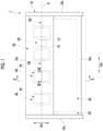
Fig. 1 is a plan view viewed from above showing a schematic configuration of an indoor unit according to a first embodiment of the present disclosure. -
Fig. 2 is a cross-sectional view taken along line II-II inFig. 1 . -
Fig. 3 is a cross-sectional view taken along line III-III inFig. 1 . -
Fig. 4 is an enlarged cross-sectional view of a IV part ofFig. 3 . -
Fig. 5 is a cross-sectional view taken along line V-V ofFig. 4 . -
Fig. 6 is a cross-sectional view of a boss part and a fastening member according to a second embodiment of the present disclosure. - Hereinafter, an air conditioner 1 according to an embodiment of the present disclosure will be described with reference to
Figs. 1 to 5 . - The air conditioner 1 shown in
Fig. 1 is an indoor unit having a ceiling-suspended shape that is supported by a ceiling of a living room or the like. The air conditioner 1 is connected to an outdoor unit which is not shown by a refrigerant pipe which is not shown. The air conditioner 1 forms a refrigerating cycle which is not shown in which a refrigerant circulates, together with an outdoor unit and a refrigerant pipe. - As shown in
Figs. 1 and2 , the air conditioner 1 includes acasing 10, aheat exchanger 20, adrain pan 21, abaffle plate 22, and ablower unit 30. - The
casing 10 accommodates various devices and members of the air conditioner 1. Thecasing 10 is suspended from a ceiling. Thecasing 10 is formed of, for example, sheet metal such as iron. The outer shape of thecasing 10 is a rectangular parallelepiped. Thecasing 10 includes anupper plate 10a, alower plate 10b, andside plates 10c. Theupper plate 10a and thelower plate 10b extend in the horizontal direction. Theupper plate 10a and thelower plate 10b are formed in a rectangular shape when viewed in the vertical direction. Fourside plates 10c are provided between theupper plate 10a and thelower plate 10b. Theside plate 10c extends in the vertical direction. Theside plates 10c connect an outer peripheral edge of theupper plate 10a and an outer peripheral edge of thelower plate 10b. - Hereinafter, a longitudinal direction of the
upper plate 10a and thelower plate 10b of thecasing 10 may be referred to as a width direction Dw of thecasing 10. A direction orthogonal to the width direction Dw of thecasing 10, and a short direction of theupper plate 10a and thelower plate 10b of thecasing 10 may be referred to as a depth direction Dd of thecasing 10. A direction orthogonal to the width direction Dw and the depth direction Dd of thecasing 10 may be referred to as a height direction Dh of thecasing 10. The height direction Dh coincides with the vertical direction. - The height dimension of the
casing 10 is smaller than the width dimension and the depth dimension of thecasing 10. - The intake port 11 is formed in one side of the
lower plate 10b in the depth direction Dd. The intake port 11 penetrates thelower plate 10b in the height direction Dh. - The
discharge port 12 is formed in theside plate 10c positioned on the side opposite to the intake port 11 in the depth direction Dd among the fourside plates 10c. Thedischarge port 12 penetrates theside plate 10c of thecasing 10 in the depth direction Dd. - The
casing 10 forms a flow path F of air between the intake port 11 and thedischarge port 12. - A refrigerant circulating inside the refrigerating cycle flows inside the
heat exchanger 20. Theheat exchanger 20 acts as an evaporator during a cooling operation and acts as a condenser during a heating operation. Theheat exchanger 20 is provided in thecasing 10. Theheat exchanger 20 is disposed on thedischarge port 12 side in the depth direction Dd. Theheat exchanger 20 faces thedischarge port 12 in the depth direction Dd. Theheat exchanger 20 is formed in a rectangular parallelepiped shape extending in the width direction Dw. Theheat exchanger 20 is disposed in a state of being inclined in the depth direction Dd. For this reason, the upper end part of theheat exchanger 20 is positioned closer to thedischarge port 12 than the lower end part of theheat exchanger 20. Theheat exchanger 20 is fixed to thecasing 10 at both end parts in the width direction Dw. - The
heat exchanger 20 is a fin-and-tube type heat exchanger. Theheat exchanger 20 includes aheat transfer pipe 23 and afin 24. Theheat transfer pipe 23 has a plurality oflinear parts 23a extending in the width direction Dw, and a plurality of curved line parts (not shown) connecting the adjacentlinear parts 23a at the end parts in the width direction Dw. A refrigerant flow path is formed in theheat transfer pipe 23. Thefin 24 extends in a direction intersecting theheat transfer pipe 23, and increases the heat transfer area of theheat transfer pipe 23. A plurality offins 24 are provided side by side in the width direction Dw. - The
drain pan 21 is provided in thecasing 10. Thedrain pan 21 is disposed below theheat exchanger 20. Thedrain pan 21 receives the drain water that has flowed out from theheat exchanger 20 during the cooling operation. Thedrain pan 21 is formed of, for example, a non-conductive synthetic resin, a foamed resin, or the like. Thedrain pan 21 is a plate-shaped member that extends along thelower plate 10b of thecasing 10. - The
baffle plate 22 is provided at an end part of theheat exchanger 20 on one side in the width direction Dw. Thebaffle plate 22 shields a portion of the flow path F in thecasing 10, which is on the outer side in the width direction Dw from theheat exchanger 20, and suppresses the flow of the air in thecasing 10 without coming into contact with theheat exchanger 20. Thebaffle plate 22 is formed of an iron plate or an iron plate covered with a zinc plating layer. Thebaffle plate 22 is formed in a band shape along a surface of theheat exchanger 20 that faces thedischarge port 12. - The
blower unit 30 is provided inside thecasing 10. Theblower unit 30 blows air from the intake port 11 toward thedischarge port 12. Theblower unit 30 is disposed in thecasing 10 on a side opposite to thedischarge port 12 with theheat exchanger 20 interposed therebetween. In other words, theheat exchanger 20 is provided between theblower unit 30 and thedischarge port 12 in thecasing 10. Theblower unit 30 faces the intake port 11 in the height direction Dh. Theblower unit 30 includes amotor 50, ashaft 60, afan casing 40, afan 70, and afastening member 90. - The
motor 50 is disposed at a position in thecasing 10 that is offset to one side in the width direction Dw (the side opposite to thebaffle plate 22 in the width direction Dw). Themotor 50 is a dual-shaft motor having tworotary shafts 51 protruding to both outer sides in the width direction Dw. Theshaft 60 is connected to each of therotary shafts 51. - Two
shafts 60 are provided. Eachshaft 60 is formed in a cylindrical shape having a hollow portion. Each of theshafts 60 is externally fitted to each of tworotary shafts 51 of themotor 50. Theshaft 60 is rotationally driven around the axial line O by themotor 50. The axial line O direction of theshaft 60 coincides with the width direction Dw. Theshaft 60 is formed of, for example, a metal such as stainless steel. Each of theshafts 60 extends in a direction in which theshaft 60 is separated from themotor 50 in the width direction Dw. Of the twoshafts 60, theshaft 60 extending to the other side (thebaffle plate 22 side in the width direction Dw) in the width direction Dw is longer than theshaft 60 extending to the one side (the side opposite to thebaffle plate 22 in the width direction Dw) in the width direction Dw. Each of theshafts 60 is rotatably supported around the axial line O at an end part on a side opposite to themotor 50 in the axial line O direction. The outercircumferential surface 61 of theshaft 60 has a uniform outer diameter along the axial line O direction. Theshaft 60 has a recessedpart 62 on an outer circumferential surface 61 (refer toFig. 3 ). - Hereinafter, the radial direction of the
shaft 60 with respect to the axial line O may be simply referred to as a "radial direction". The circumferential direction with respect to the axial line O of theshaft 60 may be simply referred to as a "circumferential direction". - The recessed
parts 62 are respectively provided in the twoshafts 60. Three recessedparts 62 are provided in thelonger shaft 60 of the twoshafts 60. The three recessedparts 62 are arranged at equal intervals in the axial line O direction. One recessedpart 62 is provided at the center of theshort shaft 60 of the twoshafts 60 in the axial line O direction. - As shown in
Figs. 3 to 5 , the recessedpart 62 is formed so that a part of the outercircumferential surface 61 of theshaft 60 in the circumferential direction and the axial line O direction is retracted to the radial inner side. The recessedpart 62 has a groove shape extending along the entire circumferential direction. The portion of theshaft 60 in which the recessedpart 62 is provided is a reduced diameter portion having a smaller diameter than the other portion of theshaft 60. The recessedpart 62 is formed in a U shape that is open toward the radial outer side when viewed in the circumferential direction. A depth dimension L1 of the recessedpart 62 in the radial direction is smaller than a width dimension L2 of the recessedpart 62 in the axial line O direction. - The recessed
part 62 has abottom part 62a and aninner side surface 62b. Thebottom part 62a has a uniform outer diameter over the entire direction along the axial line O, similarly to the outercircumferential surface 61 of theshaft 60. The inner side surfaces 62b are provided in a pair at both ends of thebottom part 62a in the axial line O direction. The pair of inner side surfaces 62b face each other in the axial line O direction. Each of theinner side surfaces 62b extends from the end part of thebottom part 62a in the direction of the axial line O to the in the radial direction. The separation distance between the pair of inner side surfaces 62b in the direction of the axial line O increases toward the radial outer side. That is, the angle formed by theinner side surface 62b and thebottom part 62a is larger than 90 degrees and smaller than 180 degrees. Theinner side surface 62b connects thebottom part 62a and the outercircumferential surface 61. - The inner diameter of the
shaft 60 described above is, for example, 1/3 or more and 2/3 or less of the outer diameter of the outercircumferential surface 61 of theshaft 60. The outer diameter of the outercircumferential surface 61 of theshaft 60 is, for example, 14 mm or more and 16 mm or less. The depth dimension L1 of the recessedpart 62 in the radial direction is, for example, 1.0 mm. - The depth dimension L1 of the recessed
part 62 in the radial direction is preferably, for example, 0.3 mm or more and 0.8 mm or less. For example, the depth dimension L1 is preferably 0.5 mm. - As shown in
Fig. 1 , fourfan casings 40 are provided at intervals in the axial line O direction of theshaft 60. Eachfan casing 40 is provided at a position overlapping each recessed part 62 (refer toFig. 3 ) in the radial direction. Thefan casing 40 is formed of, for example, sheet metal such as iron, similarly to thecasing 10. A space in which thefan 70 is accommodated is formed inside thefan casing 40. - Each of a pair of side portions of the
fan casing 40 facing each other in the width direction Dw has afan intake port 41. A pair offan intake ports 41 are provided to face each other in the width direction Dw. Each of thefan intake ports 41 penetrates thefan casing 40 in the width direction Dw. Thefan intake port 41 is formed in a perfectly circular shape when viewed in the width direction Dw. Theshaft 60 is inserted into thefan intake port 41. Thefan intake port 41 is coaxial with theshaft 60. - A
fan discharge port 42 is formed in a side portion of thefan casing 40 facing theheat exchanger 20. Thefan discharge port 42 penetrates thefan casing 40 in the depth direction Dd. Thefan discharge port 42 faces theheat exchanger 20 in the depth direction Dd. - The
fan casing 40 forms an air flow path F between thefan intake port 41 and thefan discharge port 42. - As shown in
Figs. 1 and2 , thefans 70 are provided one by one in therespective fan casings 40. Fourfans 70 are provided. Thefan 70 is a sirocco fan. Thefan 70 is inserted into theshaft 60. Thefan 70 is integrally rotationally driven with theshaft 60 to generate a flow of air from the intake port 11 toward thedischarge port 12. Fourfans 70 are provided at intervals in the axial line O direction of theshaft 60. Eachfan 70 is provided at a position overlapping each recessedpart 62 in the radial direction. - As shown in
Fig. 3 , thefan 70 includes aboss part 80, aconnection part 71, and acylindrical blade part 72. - As shown in
Figs. 4 and 5 , theboss part 80 is a cylindrical member. Theboss part 80 is externally fitted to the outercircumferential surface 61 of theshaft 60. The inner diameter of theboss part 80 is slightly larger than the outer diameter of the outercircumferential surface 61 of theshaft 60. Theboss part 80 is provided to overlap the recessedpart 62 from the radial outer side with respect to the recessedpart 62 on one side in the axial line O direction. Theboss part 80 covers the recessedpart 62 from the outer circumferential side along the axial line O direction and the circumferential direction. Theboss part 80 is formed of, for example, a metal such as aluminum. The end surfaces 83 of theboss part 80 on both sides in the axial line O direction are positioned on the outer side in the axial line O direction with respect to the recessedpart 62. Both end parts of theinner surface 82 of theboss part 80 in the axial line O direction are in contact with the outercircumferential surface 61 of theshaft 60. A through-hole 84 penetrating theboss part 80 in the radial direction is formed on one side of theboss part 80 in the axial line O direction. A screw groove which is not shown is formed on an inner circumferential surface of the through-hole 84. The through-hole 84 is formed in a perfectly circular shape when viewed in the radial direction. - As shown in
Fig. 3 , theconnection part 71 protrudes from theouter surface 81 of theboss part 80 to the radial outer side. Theconnection part 71 is provided on a side opposite to the through-hole 84 in the axial line O direction. Theconnection part 71 is a circular plate-shaped member coaxial with theboss part 80. Theconnection part 71 is fixed to theboss part 80 by using a fixing member which is not shown. Theconnection part 71 is formed of, for example, a metal such as aluminum. - The
cylindrical blade part 72 is connected to theconnection part 71 on the radial outer side. Thecylindrical blade part 72 is coaxial with theboss part 80. Thecylindrical blade part 72 is formed of, for example, a metal such as aluminum. Thecylindrical blade part 72 includes ablade 72a and aring 73. A plurality of theblades 72a are provided to be arranged at equal intervals in the circumferential direction. Each of theblades 72a extends in the axial line O direction. Theblade 72a is provided to penetrate the outer peripheral edge of theconnection part 71 in the axial line O direction. Theblades 72a are joined to theconnection part 71, for example, by welding at the center in the axial line O direction. The plurality ofrings 73 are provided one by one on both the outer sides in the axial line O direction with respect to the plurality ofblades 72a. Thering 73 connects the plurality ofblades 72a arranged in the circumferential direction. Thering 73 is joined to theblade 72a, for example, by welding. - As shown in
Fig. 4 , thefastening member 90 is a stopper screw formed in a cylindrical shape. Thefastening member 90 is inserted into the through-hole 84 of theboss part 80. In other words, thefastening member 90 is provided to penetrate theboss part 80. Thefastening member 90 is formed of, for example, a metal such as stainless steel. Thefastening member 90 hasscrew threads 90a on an outer circumferential surface. Thescrew thread 90a of thefastening member 90 is screwed into the screw groove of the through-hole 84. - A
tip part 91 facing theshaft 60 side of thefastening member 90 abuts on thebottom part 62a of the recessedpart 62. The diameter of thetip part 91 is reduced as thetip part 91 approaches thebottom part 62a. Thetip part 91 is fitted to thebottom part 62a. Atip surface 92 of thetip part 91 that is positioned closest to theshaft 60 has a flat surface. - Hereinafter, a procedure for fastening the
fan 70 and theshaft 60 by thefastening member 90 will be described in detail with reference toFig. 5 . - First, the
boss part 80 is inserted into theshaft 60. Next, the position of thefan 70 in the axial line O direction is adjusted such that theboss part 80 covers the recessedpart 62 from the radial outer side. Next, thefastening member 90 is screwed into the through-hole 84 of theboss part 80, and thescrew thread 90a of thefastening member 90 and the screw groove (not shown) of the through-hole 84 are screwed together. Then, when thetip part 91 of thefastening member 90 is brought into contact with thebottom part 62a of the recessedpart 62, a frictional force is generated between thetip part 91 of thefastening member 90 and thebottom part 62a of the recessedpart 62. Accordingly, the rotation of thefastening member 90 around the axial line O with respect to theshaft 60 is suppressed. Theboss part 80 is screwed to thefastening member 90. For this reason, the rotation of thefan 70 around the axial line O with respect to theshaft 60 is suppressed by the frictional force between the fasteningmember 90 and theshaft 60. - In a case where the
fan 70 is deviated with respect to theshaft 60 when theshaft 60 is rotated, thefastening member 90 is further screwed into the through-hole 84 of theboss part 80, and the load of thefastening member 90 on theshaft 60 is increased. Accordingly, the frictional force between the fasteningmember 90 and theshaft 60 is increased, and the rotation of thefan 70 around the axial line O with respect to theshaft 60 can be further suppressed. Thefastening member 90 is screwed until a frictional force is generated to such an extent that thefan 70 does not move with respect to therotating shaft 60. In this way, thefan 70 and theshaft 60 are fastened to each other. - In the present embodiment, the
shaft 60 has a recessedpart 62 that is recessed radially inward from the outercircumferential surface 61. Theboss part 80 is externally fitted to the outercircumferential surface 61 of theshaft 60 and is provided to overlap the recessedpart 62 from the radial outer side. Thefastening member 90 penetrates theboss part 80 in the radial direction and comes into contact with thebottom part 62a of the recessedpart 62. - The
fan 70 can be fastened to theshaft 60 by thefastening member 90. Accordingly, thefan 70 can be fixed to therotating shaft 60 without deviation. - Further, the fastening of the
boss part 80 and theshaft 60 can be released only by removing thefastening member 90. Therefore, thefan 70 can be easily pulled out from theshaft 60. - In addition, when the load on the
shaft 60 by thefastening member 90 exceeds a certain value, thetip part 91 of thefastening member 90 may scrape theshaft 60 to generate a burr B. In the present embodiment, even when the burr B is generated, the burr B can be accommodated in the recessedpart 62 and it is possible to suppress the burr B from protruding to the radial outer side with respect to the outercircumferential surface 61 of theshaft 60. In other words, the thickness of the burr B can be absorbed, and an increase in the outer diameter of the outercircumferential surface 61 of theshaft 60 can be suppressed. For this reason, when thefan 70 is pulled out from theshaft 60, the burr B can be suppressed from being caught by thefan 70. Therefore, even when the burr B is generated at the time of the fastening by thefastening member 90, thefan 70 can be easily pulled out from theshaft 60. - In the present embodiment, the
boss part 80 covers the recessedpart 62 from the outer circumferential side in the direction along the axial line O and in the circumferential direction. - The
boss part 80 can suppress the scattering of the burr B from the recessedpart 62 to the outside in the axial line O direction. In addition, when thefan 70 is pulled out from theshaft 60, the burr B can be further suppressed from being caught by thefan 70. Therefore, even when the burr B is generated at the time of the fastening by thefastening member 90, thefan 70 can be more easily pulled out from theshaft 60. - In addition, the
boss part 80 can be attached to theshaft 60 in a state where both end parts of theboss part 80 in the axial line O direction are in contact with the outercircumferential surface 61 of theshaft 60. Accordingly, since theboss part 80 is supported on both sides in the axial line O direction, thefan 70 can be mounted on theshaft 60 in a stable state. Therefore, it is possible to suppress an increase in vibration caused by the rotation of thefan 70, as compared with a case where theboss part 80 is supported on one side in the axial line O direction. - In the present embodiment, the recessed
part 62 has a groove shape extending over the entire circumferential direction. - Accordingly, the recessed
part 62 can be provided only by forming a part of the outercircumferential surface 61 of theshaft 60 in the axial line O direction in a groove shape extending along the entire circumferential direction. Therefore, the manufacturing process of the air conditioner 1 can be simplified. - In the present embodiment, the
tip part 91 of thefastening member 90 is fitted to thebottom part 62a. - Accordingly, a fastening force of the fastening member can be increased. Therefore, the
fan 70 can be more firmly fixed not to be deviated with respect to therotating shaft 60. - In the present embodiment, the depth dimension L1 of the recessed
part 62 in the radial direction is preferably, for example, 0.3 mm or more and 0.8 mm or less. In this case, it is possible to reliably suppress the protrusion of the burr B to the radial outer side with respect to the outercircumferential surface 61 of theshaft 60. - In addition, for example, 0.5 mm is most preferable as the depth dimension L1. In this case, the strength of the
shaft 60 can be ensured while suppressing the burr B from protruding more favorably to the radial outer side with respect to the outercircumferential surface 61 of theshaft 60. - Hereinafter, an
air conditioner 101 of a second embodiment of the present disclosure will be described with reference toFig. 6 . In the second embodiment, the same reference numerals will be assigned to configuration elements which are the same as those according to the first embodiment, and detailed description thereof will be appropriately omitted. - As shown in
Fig. 6 , a recessedpart 65 is a cutout part formed by cutting out a part of the outercircumferential surface 61 of ashaft 160. Abottom part 66 of the recessedpart 65 has a flat shape along the axial line O direction and the radial direction. - In the present embodiment, the
bottom part 66 of the recessedpart 65 has a flat surface. - The
bottom part 66 of the recessedpart 65 can suppress thefastening member 90 from moving in the circumferential direction. Accordingly, it is possible to suppress thefan 70 from relatively rotating with respect to theshaft 160. Therefore, thefan 70 can be more firmly fixed not to be deviated with respect to therotating shaft 160. - The embodiments of the present disclosure have been described in detail with reference to the drawings. However, the specific configuration is not limited to the embodiments of the present disclosure, and includes design changes and the like without departing from the gist of the present disclosure.
- In the above embodiment, the
air conditioners 1 and 101 are the indoor units. However, the present disclosure is not limited thereto, and theair conditioners 1 and 101 may be, for example, the outdoor units. - In the above embodiment, the
shafts shafts shafts parts shafts shafts parts shafts circumferential surface 61 of theshafts - In the above embodiment, the
fan 70 is a sirocco fan. However, the present disclosure is not limited thereto, and thefan 70 may be, for example, a turbo fan. - In the above embodiment, the air conditioner 1 includes four
fans 70. However, the present disclosure is not limited thereto. The number offans 70 can be appropriately changed. In addition, the disposition of eachfan 70 with respect to themotor 50 can also be appropriately changed. For example, thefan 70 may be provided one by one on both sides in the axial line O direction with respect to themotor 50. In addition, thefan 70 may be provided with two fans on each of both sides in the axial line O direction with respect to themotor 50. - In the above embodiment, the
boss part 80 is formed in a cylindrical shape. However, the present disclosure is not limited thereto. Theboss part 80 may be formed in a cylindrical shape. For example, an inner circumferential surface of theboss part 80 may be formed in a perfect circular shape when viewed in the axial line O direction, and an outercircumferential surface 61 of theboss part 80 may be formed in a polygonal shape when viewed in the axial line O direction. - In the above embodiment, the
connection part 71 is a circular plate-shaped member. However, the present disclosure is not limited thereto. Theconnection part 71 may protrude from theboss part 80 to the radial outer side. Theconnection part 71 may be provided only in a part of the region in the circumferential direction in theouter surface 81 of theboss part 80. However, in a case where theconnection part 71 is provided along the entire circumferential direction of theouter surface 81 of theboss part 80, it is possible to suppress the weight balance of theentire fan 70 from being biased in the circumferential direction, and thus, there is an advantage in that the rotation of thefan 70 is stabilized. - Although the
boss part 80 is formed of, for example, a metal such as aluminum, the present disclosure is not limited thereto, and theboss part 80 may be formed of, for example, a synthetic resin. - The
connection part 71 and thecylindrical blade part 72 are formed of, for example, a metal such as aluminum, but the present invention is not limited thereto, and may be formed of, for example, a synthetic resin. In this case, theconnection part 71 and thecylindrical blade part 72 are integrally formed by resin molding using a mold. - In the above embodiment, the
tip surface 92 of thetip part 91 of thefastening member 90 that is positioned closest to theshafts fastening member 90 may be a so-called pointed bolt having asharp tip part 91. - The
air conditioners 1 and 101 for a vehicle in each embodiment is grasped as follows, for example. -
- (1) Air conditioners 1 and 101 according to an first aspect includes a casing 10 that forms a flow path F between an intake port 11 and a discharge port 12; an blower unit 30 that is provided in the casing 10 and blows air from the intake port 11 toward the discharge port 12; and a heat exchanger 20 that is provided between the blower unit 30 and the discharge port 12 in the casing 10, in which the blower unit 30 includes a motor 50, shafts 60 and 160 that are rotationally driven around an axial line O by the motor 50, and includes an outer circumferential surface 61 that has a uniform outer diameter along an axial line direction and recessed parts 62 and 65 that are recessed from the outer circumferential surface 61 toward a radial inner side, a fan 70 that includes a cylindrical boss part 80 that is provided to be externally fitted to the outer circumferential surface 61 of the shafts 60 and 160 and to overlap with the recessed parts 62 and 65 from a radial outer side, a connection part 71 that protrudes from the boss part 80 to the radial outer side of the axial line O, and a cylindrical blade part 72 that is connected to the radial outer side of the connection part 71 and is coaxial with the boss part 80, and a fastening member 90 that passes through the boss part 80 in a radial direction and abuts on bottom parts 62a and 66 of the recessed parts 62 and 65.
Thefan 70 can be fastened to theshafts fastening member 90. Further, thefastening member 90 can be removed to release the fastening between theboss part 80 and theshafts tip part 91 of thefastening member 90 scrapes theshafts parts circumferential surface 61 of theshafts fan 70 is pulled out from theshafts fan 70. - (2)
Air conditioners 1 and 101 according to a second aspect are theair conditioners 1 and 101 of (1), in which theboss part 80 may cover the recessedparts
Theboss part 80 can suppress the scattering of the burr B from the recessedparts - (3) An air conditioner 1 according to a third aspect is the air conditioner 1 of (1) or (2), in which the recessed
part 62 may have a groove shape extending along an entire circumferential direction.
Accordingly, the recessedpart 62 can be provided only by forming a part of the outercircumferential surface 61 of theshaft 60 in the axial line O direction in a groove shape extending along the entire circumferential direction. - (4) An
air conditioner 101 according to a fourth aspect is theair conditioner 101 of (1) or (2), thebottom part 66 of the recessedpart 65 may have a flat shpae. - The
bottom part 66 of the recessedpart 65 can suppress thefastening member 90 from moving in the circumferential direction. Accordingly, it is possible to suppress thefan 70 from relatively rotating with respect to theshaft 160. - According to the air conditioner of the present disclosure, the fan can be easily removed from the shaft while the fan is fixed to the rotating shaft without deviation.
-
- 1:
- air conditioner
- 10:
- casing
- 10a:
- upper plate
- 10b:
- lower plate
- 10c:
- side plate
- 11:
- intake port
- 12:
- discharge port
- 20:
- heat exchanger
- 21:
- drain pan
- 22:
- baffle plate
- 23:
- heat transfer pipe
- 23a:
- linear part
- 24:
- fin
- 30:
- blower unit
- 40:
- fan casing
- 41:
- fan intake port
- 42:
- fan discharge port
- 50:
- motor
- 51:
- rotary shaft
- 60:
- shaft
- 61:
- outer circumferential surface
- 62:
- recessed part
- 62a:
- bottom part
- 62b:
- inner side surface
- 65:
- recessed part
- 66:
- bottom part
- 70:
- fan
- 71:
- connection part
- 72:
- cylindrical blade part
- 72a:
- blade
- 73:
- ring
- 80:
- boss part
- 81:
- outer surface
- 82:
- inner surface
- 83:
- end surface
- 84:
- through-hole
- 90:
- fastening member
- 90a:
- screw thread
- 91:
- tip part
- 92:
- tip surface
- 101:
- air conditioner
- 160:
- shaft
- B:
- burr
- Dd:
- depth direction
- Dw:
- width direction
- Dh:
- height direction
- F:
- flow path
- L1:
- depth dimension
- L2:
- width dimension
- O:
- axial line
Claims (4)
- An air conditioner comprising:a casing that forms a flow path between an intake port and a discharge port;an blower unit that is provided in the casing and blows air from the intake port toward the discharge port; anda heat exchanger that is provided between the blower unit and the discharge port in the casing,wherein the blower unit includesa motor,a shaft that is rotationally driven around an axial line by the motor, and includes an outer circumferential surface that has a uniform outer diameter along an axial line direction and a recessed part that is recessed from the outer circumferential surface toward a radial inner side,a fan that includes a cylindrical boss part that is provided to be externally fitted to the outer circumferential surface of the shaft and to overlap with the recessed part from a radial outer side, a connection part that protrudes from the boss part to the radial outer side of the axial line, and a cylindrical blade part that is connected to the radial outer side of the connection part and is coaxial with the boss part, anda fastening member that passes through the boss part in a radial direction and abuts on a bottom part of the recessed part.
- The air conditioner according to Claim 1,
wherein the boss part covers the recessed part from an outer circumferential side along the axial line direction and a circumferential direction. - The air conditioner according to Claim 1 or 2,
wherein the recessed part has a groove shape extending along an entire circumferential direction. - The air conditioner according to Claim 1 or 2,
wherein the bottom part of the recessed part has a flat shape.
Applications Claiming Priority (2)
| Application Number | Priority Date | Filing Date | Title |
|---|---|---|---|
| JP2021187985A JP7818933B2 (en) | 2021-11-18 | 2021-11-18 | air conditioner |
| PCT/JP2022/040882 WO2023090151A1 (en) | 2021-11-18 | 2022-11-01 | Air conditioner |
Publications (2)
| Publication Number | Publication Date |
|---|---|
| EP4407191A1 true EP4407191A1 (en) | 2024-07-31 |
| EP4407191A4 EP4407191A4 (en) | 2024-11-20 |
Family
ID=86396835
Family Applications (1)
| Application Number | Title | Priority Date | Filing Date |
|---|---|---|---|
| EP22895433.5A Pending EP4407191A4 (en) | 2021-11-18 | 2022-11-01 | AIR CONDITIONER |
Country Status (4)
| Country | Link |
|---|---|
| EP (1) | EP4407191A4 (en) |
| JP (1) | JP7818933B2 (en) |
| CN (1) | CN118234955A (en) |
| WO (1) | WO2023090151A1 (en) |
Family Cites Families (14)
| Publication number | Priority date | Publication date | Assignee | Title |
|---|---|---|---|---|
| JPS51163512U (en) * | 1975-06-20 | 1976-12-27 | ||
| JPH0545836Y2 (en) * | 1988-11-24 | 1993-11-26 | ||
| JPH0617794A (en) * | 1992-07-01 | 1994-01-25 | Matsushita Electric Ind Co Ltd | Fan mounting device |
| JP2980222B2 (en) * | 1993-09-08 | 1999-11-22 | 船井電機株式会社 | Sirocco fan |
| JPH1177447A (en) | 1997-09-04 | 1999-03-23 | Denso Corp | Rotating body fastening structure |
| KR100397303B1 (en) * | 1999-04-07 | 2003-09-06 | 주식회사 대우일렉트로닉스 | Blow fan assembly for an air conditioner |
| KR20050099352A (en) * | 2004-04-09 | 2005-10-13 | 엘지전자 주식회사 | Front suction/discharge type outdoor unit for air conditioner |
| CN1900616B (en) * | 2005-07-19 | 2010-12-22 | 乐金电子(天津)电器有限公司 | Air supply device |
| JP2013079617A (en) * | 2011-10-05 | 2013-05-02 | Hitachi Appliances Inc | Air conditioner |
| EP3462038B1 (en) * | 2017-07-31 | 2020-07-08 | Mitsubishi Electric Corporation | Fan and indoor machine of air conditioning device provided with fan |
| CN109681460B (en) * | 2018-12-29 | 2024-07-02 | 珠海格力电器股份有限公司 | Fan blade motor shaft fixing structure, fan and air conditioner |
| CN212481493U (en) * | 2020-04-30 | 2021-02-05 | 海信(广东)空调有限公司 | Fan Assembly and Indoor Unit |
| WO2021219110A1 (en) * | 2020-04-30 | 2021-11-04 | 海信(广东)空调有限公司 | Air conditioner indoor unit capable of being disassembled and cleaned |
| JP7509581B2 (en) | 2020-06-02 | 2024-07-02 | 日東電工株式会社 | Adhesive sheets for semiconductor processing |
-
2021
- 2021-11-18 JP JP2021187985A patent/JP7818933B2/en active Active
-
2022
- 2022-11-01 EP EP22895433.5A patent/EP4407191A4/en active Pending
- 2022-11-01 CN CN202280071307.3A patent/CN118234955A/en active Pending
- 2022-11-01 WO PCT/JP2022/040882 patent/WO2023090151A1/en not_active Ceased
Also Published As
| Publication number | Publication date |
|---|---|
| JP2023074840A (en) | 2023-05-30 |
| EP4407191A4 (en) | 2024-11-20 |
| WO2023090151A1 (en) | 2023-05-25 |
| JP7818933B2 (en) | 2026-02-24 |
| CN118234955A (en) | 2024-06-21 |
Similar Documents
| Publication | Publication Date | Title |
|---|---|---|
| US9995303B2 (en) | Air conditioner | |
| EP3372839B1 (en) | Blower, outdoor unit, and refrigeration cycle apparatus | |
| EP3168481A1 (en) | Propeller fan and blower unit | |
| EP3896290B1 (en) | Centrifugal fan and air conditioner | |
| KR101788008B1 (en) | Centrifugal fan and air conditioner having the same | |
| EP3070410A1 (en) | Outdoor unit of air conditioner | |
| JP5917159B2 (en) | Air conditioner outdoor unit | |
| WO2020261379A1 (en) | Axial flow fan, blowing device, and refrigeration cycle device | |
| JP7818933B2 (en) | air conditioner | |
| JP6463497B2 (en) | Blower, outdoor unit and refrigeration cycle apparatus | |
| EP4431747A1 (en) | Cross-flow fan, blowing device, and refrigeration cycle device | |
| EP3534015B1 (en) | Propeller fan, outdoor machine, and refrigeration cycle apparatus | |
| EP3943829B1 (en) | Air conditioner | |
| EP3748238B1 (en) | AIR CONDITIONING EMBED IN A CEILING | |
| CN110017292B (en) | Alignment and centering features for fan assembly | |
| EP4343251A1 (en) | Heat exchanger and outdoor unit | |
| KR20050092832A (en) | Air conditioner | |
| US20250027661A1 (en) | Indoor unit and air conditioning device comprising the same | |
| CN120867993A (en) | Oil baffle plate assembly, rotor assembly and compressor | |
| WO1999067535A1 (en) | Mounting of fan to motor drive shaft | |
| CN221973899U (en) | Centrifugal fans and air handling devices | |
| JP7378574B2 (en) | Indoor unit and air conditioner | |
| US20250102157A1 (en) | Air conditioner outdoor unit and air conditioner | |
| JP7378505B2 (en) | Centrifugal blower and air conditioner equipped with it | |
| KR100833851B1 (en) | Ceiling air conditioners |
Legal Events
| Date | Code | Title | Description |
|---|---|---|---|
| STAA | Information on the status of an ep patent application or granted ep patent |
Free format text: STATUS: THE INTERNATIONAL PUBLICATION HAS BEEN MADE |
|
| PUAI | Public reference made under article 153(3) epc to a published international application that has entered the european phase |
Free format text: ORIGINAL CODE: 0009012 |
|
| STAA | Information on the status of an ep patent application or granted ep patent |
Free format text: STATUS: REQUEST FOR EXAMINATION WAS MADE |
|
| 17P | Request for examination filed |
Effective date: 20240424 |
|
| AK | Designated contracting states |
Kind code of ref document: A1 Designated state(s): AL AT BE BG CH CY CZ DE DK EE ES FI FR GB GR HR HU IE IS IT LI LT LU LV MC ME MK MT NL NO PL PT RO RS SE SI SK SM TR |
|
| A4 | Supplementary search report drawn up and despatched |
Effective date: 20241021 |
|
| RIC1 | Information provided on ipc code assigned before grant |
Ipc: F24F 1/0018 20190101ALI20241015BHEP Ipc: F04D 29/62 20060101ALI20241015BHEP Ipc: F04D 29/26 20060101ALI20241015BHEP Ipc: F24F 1/0022 20190101ALI20241015BHEP Ipc: F04D 29/28 20060101AFI20241015BHEP |
|
| DAV | Request for validation of the european patent (deleted) | ||
| DAX | Request for extension of the european patent (deleted) |