EP4407179B1 - Axialkolbenpumpe - Google Patents
Axialkolbenpumpe Download PDFInfo
- Publication number
- EP4407179B1 EP4407179B1 EP22741544.5A EP22741544A EP4407179B1 EP 4407179 B1 EP4407179 B1 EP 4407179B1 EP 22741544 A EP22741544 A EP 22741544A EP 4407179 B1 EP4407179 B1 EP 4407179B1
- Authority
- EP
- European Patent Office
- Prior art keywords
- plate
- piston pump
- axial piston
- coupled
- pistons
- Prior art date
- Legal status (The legal status is an assumption and is not a legal conclusion. Google has not performed a legal analysis and makes no representation as to the accuracy of the status listed.)
- Active
Links
Images


Classifications
-
- F—MECHANICAL ENGINEERING; LIGHTING; HEATING; WEAPONS; BLASTING
- F04—POSITIVE - DISPLACEMENT MACHINES FOR LIQUIDS; PUMPS FOR LIQUIDS OR ELASTIC FLUIDS
- F04B—POSITIVE-DISPLACEMENT MACHINES FOR LIQUIDS; PUMPS
- F04B1/00—Multi-cylinder machines or pumps characterised by number or arrangement of cylinders
- F04B1/12—Multi-cylinder machines or pumps characterised by number or arrangement of cylinders having cylinder axes coaxial with, or parallel or inclined to, main shaft axis
- F04B1/14—Multi-cylinder machines or pumps characterised by number or arrangement of cylinders having cylinder axes coaxial with, or parallel or inclined to, main shaft axis having stationary cylinders
-
- F—MECHANICAL ENGINEERING; LIGHTING; HEATING; WEAPONS; BLASTING
- F01—MACHINES OR ENGINES IN GENERAL; ENGINE PLANTS IN GENERAL; STEAM ENGINES
- F01B—MACHINES OR ENGINES, IN GENERAL OR OF POSITIVE-DISPLACEMENT TYPE, e.g. STEAM ENGINES
- F01B3/00—Reciprocating-piston machines or engines with cylinder axes coaxial with, or parallel or inclined to, main shaft axis
- F01B3/02—Reciprocating-piston machines or engines with cylinder axes coaxial with, or parallel or inclined to, main shaft axis with wobble-plate
-
- F—MECHANICAL ENGINEERING; LIGHTING; HEATING; WEAPONS; BLASTING
- F01—MACHINES OR ENGINES IN GENERAL; ENGINE PLANTS IN GENERAL; STEAM ENGINES
- F01B—MACHINES OR ENGINES, IN GENERAL OR OF POSITIVE-DISPLACEMENT TYPE, e.g. STEAM ENGINES
- F01B3/00—Reciprocating-piston machines or engines with cylinder axes coaxial with, or parallel or inclined to, main shaft axis
- F01B3/10—Control of working-fluid admission or discharge peculiar thereto
- F01B3/101—Control of working-fluid admission or discharge peculiar thereto for machines with stationary cylinders
- F01B3/102—Changing the piston stroke by changing the position of the swash plate
-
- F—MECHANICAL ENGINEERING; LIGHTING; HEATING; WEAPONS; BLASTING
- F04—POSITIVE - DISPLACEMENT MACHINES FOR LIQUIDS; PUMPS FOR LIQUIDS OR ELASTIC FLUIDS
- F04B—POSITIVE-DISPLACEMENT MACHINES FOR LIQUIDS; PUMPS
- F04B1/00—Multi-cylinder machines or pumps characterised by number or arrangement of cylinders
- F04B1/12—Multi-cylinder machines or pumps characterised by number or arrangement of cylinders having cylinder axes coaxial with, or parallel or inclined to, main shaft axis
- F04B1/14—Multi-cylinder machines or pumps characterised by number or arrangement of cylinders having cylinder axes coaxial with, or parallel or inclined to, main shaft axis having stationary cylinders
- F04B1/141—Details or component parts
- F04B1/146—Swash plates; Actuating elements
-
- F—MECHANICAL ENGINEERING; LIGHTING; HEATING; WEAPONS; BLASTING
- F04—POSITIVE - DISPLACEMENT MACHINES FOR LIQUIDS; PUMPS FOR LIQUIDS OR ELASTIC FLUIDS
- F04B—POSITIVE-DISPLACEMENT MACHINES FOR LIQUIDS; PUMPS
- F04B1/00—Multi-cylinder machines or pumps characterised by number or arrangement of cylinders
- F04B1/12—Multi-cylinder machines or pumps characterised by number or arrangement of cylinders having cylinder axes coaxial with, or parallel or inclined to, main shaft axis
- F04B1/26—Control
- F04B1/28—Control of machines or pumps with stationary cylinders
- F04B1/29—Control of machines or pumps with stationary cylinders by varying the relative positions of a swash plate and a cylinder block
- F04B1/295—Control of machines or pumps with stationary cylinders by varying the relative positions of a swash plate and a cylinder block by changing the inclination of the swash plate
-
- F—MECHANICAL ENGINEERING; LIGHTING; HEATING; WEAPONS; BLASTING
- F04—POSITIVE - DISPLACEMENT MACHINES FOR LIQUIDS; PUMPS FOR LIQUIDS OR ELASTIC FLUIDS
- F04B—POSITIVE-DISPLACEMENT MACHINES FOR LIQUIDS; PUMPS
- F04B27/00—Multi-cylinder pumps specially adapted for elastic fluids and characterised by number or arrangement of cylinders
- F04B27/08—Multi-cylinder pumps specially adapted for elastic fluids and characterised by number or arrangement of cylinders having cylinders coaxial with, or parallel or inclined to, main shaft axis
- F04B27/14—Control
- F04B27/16—Control of pumps with stationary cylinders
- F04B27/18—Control of pumps with stationary cylinders by varying the relative positions of a swash plate and a cylinder block
- F04B27/1804—Controlled by crankcase pressure
-
- F—MECHANICAL ENGINEERING; LIGHTING; HEATING; WEAPONS; BLASTING
- F03—MACHINES OR ENGINES FOR LIQUIDS; WIND, SPRING, OR WEIGHT MOTORS; PRODUCING MECHANICAL POWER OR A REACTIVE PROPULSIVE THRUST, NOT OTHERWISE PROVIDED FOR
- F03C—POSITIVE-DISPLACEMENT ENGINES DRIVEN BY LIQUIDS
- F03C1/00—Reciprocating-piston liquid engines
- F03C1/02—Reciprocating-piston liquid engines with multiple-cylinders, characterised by the number or arrangement of cylinders
- F03C1/06—Reciprocating-piston liquid engines with multiple-cylinders, characterised by the number or arrangement of cylinders with cylinder axes generally coaxial with, or parallel or inclined to, main shaft axis
- F03C1/0636—Reciprocating-piston liquid engines with multiple-cylinders, characterised by the number or arrangement of cylinders with cylinder axes generally coaxial with, or parallel or inclined to, main shaft axis having rotary cylinder block
- F03C1/0644—Component parts
- F03C1/0668—Swash or actuated plate
-
- F—MECHANICAL ENGINEERING; LIGHTING; HEATING; WEAPONS; BLASTING
- F03—MACHINES OR ENGINES FOR LIQUIDS; WIND, SPRING, OR WEIGHT MOTORS; PRODUCING MECHANICAL POWER OR A REACTIVE PROPULSIVE THRUST, NOT OTHERWISE PROVIDED FOR
- F03C—POSITIVE-DISPLACEMENT ENGINES DRIVEN BY LIQUIDS
- F03C1/00—Reciprocating-piston liquid engines
- F03C1/02—Reciprocating-piston liquid engines with multiple-cylinders, characterised by the number or arrangement of cylinders
- F03C1/06—Reciprocating-piston liquid engines with multiple-cylinders, characterised by the number or arrangement of cylinders with cylinder axes generally coaxial with, or parallel or inclined to, main shaft axis
- F03C1/0678—Control
- F03C1/0694—Control by changing the inclination of the axis of the cylinder barrel in relation to the axis of the actuated element
-
- F—MECHANICAL ENGINEERING; LIGHTING; HEATING; WEAPONS; BLASTING
- F04—POSITIVE - DISPLACEMENT MACHINES FOR LIQUIDS; PUMPS FOR LIQUIDS OR ELASTIC FLUIDS
- F04B—POSITIVE-DISPLACEMENT MACHINES FOR LIQUIDS; PUMPS
- F04B1/00—Multi-cylinder machines or pumps characterised by number or arrangement of cylinders
- F04B1/12—Multi-cylinder machines or pumps characterised by number or arrangement of cylinders having cylinder axes coaxial with, or parallel or inclined to, main shaft axis
- F04B1/20—Multi-cylinder machines or pumps characterised by number or arrangement of cylinders having cylinder axes coaxial with, or parallel or inclined to, main shaft axis having rotary cylinder block
- F04B1/2014—Details or component parts
- F04B1/2078—Swash plates
-
- F—MECHANICAL ENGINEERING; LIGHTING; HEATING; WEAPONS; BLASTING
- F04—POSITIVE - DISPLACEMENT MACHINES FOR LIQUIDS; PUMPS FOR LIQUIDS OR ELASTIC FLUIDS
- F04B—POSITIVE-DISPLACEMENT MACHINES FOR LIQUIDS; PUMPS
- F04B1/00—Multi-cylinder machines or pumps characterised by number or arrangement of cylinders
- F04B1/12—Multi-cylinder machines or pumps characterised by number or arrangement of cylinders having cylinder axes coaxial with, or parallel or inclined to, main shaft axis
- F04B1/26—Control
- F04B1/30—Control of machines or pumps with rotary cylinder blocks
- F04B1/32—Control of machines or pumps with rotary cylinder blocks by varying the relative positions of a swash plate and a cylinder block
- F04B1/328—Control of machines or pumps with rotary cylinder blocks by varying the relative positions of a swash plate and a cylinder block by changing the inclination of the axis of the cylinder barrel relative to the swash plate
Definitions
- the present invention relates to an axial piston pump for supplying a fluid, wherein the pump is volumetric with regulation of the flow rate and with regulation of the maximum pressure that it is capable of giving during the discharge at the outlet of the pump; and wherein the pump is applicable to chemical product fluids, and also to oil-hydraulic plants, without ruling out the application thereof to other fluids.
- the pump includes a characteristic regulable movement transmission system through which it is possible to vary the flow rate of the fluid at the outlet of the pump; wherein the fluid can be a liquid such as hydraulic oil, or a gaseous fluid.
- pumps with several membranes or pistons are known, wherein the flow rate or the pressure of the liquid fluid they supply cannot be mechanically regulated (it could be electrically regulated with a frequency variator to the motor).
- Radial piston and axial piston pumps are also known, wherein at least the latter have the drawback that they do not enable the flow rate of liquid fluid to be regulated.
- Single axial piston pumps have the drawbacks of supplying a liquid fluid flow with pulsations and a very low efficiency.
- Vane pumps and gear pumps are also known, wherein none of them enables the flow rate of liquid fluid that they provide to be regulated.
- axial piston oil-hydraulic pumps can be swash-plate or bent-axis. They are multi-piston pumps that provide a flow rate of liquid fluid without pulsations, while they can be regulated in flow rate and pressure, but they are not volumetric, they do not work with check valves and unlike the pump of the invention, the axial pistons, in addition to having a reciprocating movement (axial movement in both directions), rotate as a grouped assembly by way of a rotating revolver mechanism.
- Patent document US-2737894-A discloses an axial piston pump with the features of the preamble of claim 1.
- Volumetric piston pumps (excluding oil-hydraulic ones) are known: on the one hand, pumps with a single axial piston with flow rate and pressure regulation; and on the other hand, the pumps with several axial pistons, but without mechanical regulation of flow rate and pressure.
- an axial piston pump comprising a static head with parallel cavities in which the pistons are housed, which are configured to move axially in both directions within said cavities to supply a flow rate of fluid at the outlet of said cavities that are distributed in a circumferential path.
- the invention causes the multi-piston, volumetric and regulable flow rate and pressure concepts to be simultaneously fulfilled for the first time.
- the pump of the invention comprises a regulable movement transmission system that includes at least a first rotary plate, a second rotary plate that can be tilted with respect to the first rotary plate, a third rotary plate, a mobile runner with linear movement and a ball joint support in which ends of the pistons are coupled by means of end heads with double joints.
- Each double joint of the end heads that link the pistons with the ball joint support comprises a ball joint coupled between pairs of fins that form part of the ball joint support by means of a shaft, and an intermediate joint that attaches each end head to the piston by means of another shaft.
- the third plate is coupled to the mobile runner by means of an idle rotation coupling perpendicularly to the linear movement of the mobile runner; wherein the first plate drags in the rotation thereof the second plate and the third plate; and wherein the first, second and third plates, as well as the mobile runner, together with a tensioning device of the transmission system are located inside a main casing, which may contain an oil bath for lubrication.
- the second plate is linked to the third plate by means of a crank mechanism that hinges at a first end on the third plate by means of a first hinged connection, while a second end of the crank mechanism, opposite the first end, hinges on the second plate by means of a second hinged connection.
- the first plate includes curved-concave female front seats on which complementary curved-convex male front seats of the second tiltable plate rest; wherein the curvature of the first and the second front seats are equidistant from a shared centre located inside the main casing and coinciding with the centre of the crosshead on which the ball joint support also rotates.
- the ball joint support rests frontally on a second axial bearing coupled to an extension of the second plate; wherein said ball joint support adopts the tilt of said second plate at all times, without rotational movement of the ball joint support.
- the regulable movement transmission system is configured to be able to vary the stroke of the pistons in order to vary the flow rate of the fluid at the outlet of the cavities; wherein said variation is carried out by means of the linear movement of the mobile runner that modifies the tilt of the second plate and the ball joint support through the third plate and the crank mechanism.
- a crosshead mechanism that includes two pairs of axes hinges on the ball joint support; wherein a first pair of axes hinges on two aligned holes of two tabs solidly attached to the ball joint support, while the tensioning device that includes a longitudinal axis in parallel with the cavities in which the axial pistons are guided and run hinges on the second pair of axes of the crosshead mechanism; wherein the longitudinal axis is guided inside the head.
- the rotary motion transmission to the first plate is carried out by means of a planetary gear device that is coupled to a shaft connected to the first plate; wherein said planetary gear receives the rotary movement from an output shaft of an external motor element.
- the planetary gear device comprises a fixed support with an internal toothed gear and a planetary assembly that rotates coupled to the internal toothed gear.
- Said planetary assembly includes a cross-shaped mobile support and several radial pinions that rotate idly coupled to said mobile support; and wherein said radial pinions mesh on the one hand with the internal toothed crown, and on the other hand they mesh with a central pinion embedded in the output shaft of the motor element.
- the mobile runner includes threaded rods that are coupled to pinions that mesh with an external toothing of a toothed ring; wherein one of said pinions meshes with an intermediate pinion and this one with a drive pinion solidly attached to a shaft to which a control wheel is attached, which is configured to carry out the movement of the mobile runner in one or another direction, depending on the direction of rotation of said control wheel.
- a reduction gear may or may not be necessary to reduce the manual force required for actuation. All these toothed elements configure a regulation mechanism that is housed inside a front casing that is closed by means of a cover; wherein the front casing and the cover include centered and facing through hollows.
- the front casing includes an annular recess around the centered through hollow thereof wherein a first axial bearing sits frontally on which a portion of the first plate is embedded with interposition of an internal bearing embedded in one of the two tracks of said first axial bearing, while another portion of the first plate fits directly into the other paired track of said first axial bearing.
- the second plate comprises parallel walls that include the male front seats, while the first plate includes parallel hollows which the complementary parallel walls of the second plate fit in; wherein front bottoms of said parallel hollows constitute the curved-concave female front seats; and wherein the two hinged connections of the crank mechanism are perpendicular to the planes in which the parallel walls of the second plate are contained.
- the second axial bearing comprises two opposing tracks, one of which is coupled on a second internal bearing and this is embedded in one portion of the extension, while the other paired track of the second axial bearing is embedded directly in another portion of the extension abutting against a front seat of the second plate itself; wherein the ball joint support rests frontally on the track that is coupled on the second internal bearing.
- the main casing includes a side opening that is closed by a cover; wherein the main casing has two opposing end bases: first and second.
- the head is fixed outside the main casing and on the second base.
- the entire regulable movement transmission system is housed, as well as the rest of the elements related to said transmission system.
- the shared centre of the curved-concave male front seats of the second plate and the curved-convex female front seats of the first plate is located at the centre of the crosshead mechanism.
- the crosshead moves when the tensioning device is actuated, and reaches its final position in which its centre is equidistant from the first male front seat and the second female front seat, once the tensioning device has been fully actuated.
- the tensioning device comprises a support structure in which two parallel collateral wings are guided with curved recesses in which the crosshead mechanism hinges through the second shafts thereof.
- the tensioning device further comprises a longitudinal axis solidly attached to a central pinion that meshes with two lateral pinions coupled by means of threading on two immobilised screws in parallel to the two collateral wings by means of the heads thereof; wherein said pinions are axially retained; and wherein the longitudinal axis includes a hexagonal end section for being able to comfortably rotate said longitudinal shaft to axially adjust said tensioning device in order to axially adjust the transmission system assembly inside the main casing.
- the third plate comprises an outer portion formed by an annular body that is punctually coupled by tangential contact on bearings of the mobile runner with idle rotation, and an internal portion which comprises a central structure with hollows in which the first front fins of the first plate fit in.
- the support structure of the tensioning device is screwed to an intermediate sheet that forms part of the main casing, while it is located parallel to and close to the second end base.
- annular body arranged around the support structure is fixed on the intermediate sheet; wherein said annular body includes quadrangular holes in which the parts solidly attached to the pistons are fitted and guided; wherein the cross section of said parts coincides with the passageway cross section of the quadrangular holes; all this to prevent the rotation of the pistons.
- the pistons are axially guided and adjusted in holes located in a front plate that is screwed to a front area of the head opposite to a rear area wherein the outlet of the cavities is found; wherein said holes serve as a guide for the pistons.
- the inner bearings are to support the radial loads or forces, while the axial bearings are to support the axial loads or forces.
- a single bearing could be mounted that would support both axial as radial loads.
- the plate tilts but does not rotate and it is the pistons that rotate, while in the pump of the invention it is the other way around, i.e., the pistons do not rotate and the tilted plate is the one that rotates.
- the pump of the invention there is a check valve for each piston, which makes it a volumetric one.
- the pump of the invention perfectly fulfils these two conditions, for which reason it is a dosing pump for chemical products.
- the pump When the pump is applicable to an oil-hydraulic power plant, it is perfectly capable of giving high pressures, so it could also work as a pump in hydraulic circuits.
- the head In this application of the invention, the head would be inside the main casing and the lubricating fluid would be the same as the driven fluid.
- this gaseous fluid provided by the pump accumulates in a tank that forms part of a compressor, just like the pump itself.
- the head would be inside the main housing.
- the technical advantages of the pump of the invention with respect to single piston pumps are that it is much more efficient, that it gives a flow rate without pulsations, it has a much lower and constant decibel level, and it is mechanically balanced, i.e., the inertial and centrifugal forces of the mobile elements are very low.
- the technical advantage over multi-piston volumetric pumps is that it has flow rate and pressure regulation, and the technical advantage over oil-hydraulic pumps is that it is volumetric.
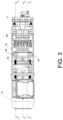
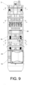
- the axial piston pump for supplying fluid comprises a regulable movement transmission system that enables the flow rate of the fluid at the pump outlet to be varied; wherein by means of said transmission system the stroke of the pistons 3 that move axially within respective cavities 16 without rotational mobility can be varied; and wherein the variation of the flow rate of fluid is carried out by means of the linear movement of a mobile runner 9 that can move in both directions in a direction parallel to the direction of the movement of the pistons 3.
- the regulable movement transmission system comprises a first rotary plate 15 associated with a second rotary plate 17 that can be tilted with respect to the first plate 15, and a third intermediate plate 11 that is also rotary; wherein the second plate 17 is linked to the third plate 11 by means of a crank mechanism 10, while the third plate 11 externally comprises an annular configuration and is coupled to the mobile runner 9 by means of an idle rotation coupling.
- the third plate 11 as shown more clearly in figure 15 , comprises an outer portion formed by an annular body 11a that is punctually coupled by tangential contact on several bearings 54 of the mobile runner 9, and an internal portion which comprises a central structure 11b with hollows in which first front fins 32 fit in parallel with the first plate 15, the rotation of which drags both the second plate 17 and the third plate 11.
- This third plate 11 includes two opposing annular stops 45 that delimit the width of a circular surface of the annular body 11a of the third plate 11 in which the bearings 54 of the mobile runner 9 fit, so that by means of said annular stops 45 the second plate 17 is mobilised axially and relative to the first plate 15 when the mobile runner 9 is axially moved; wherein said movement causes the variation of the tilt of the second plate 17.
- crank mechanism 10 that links both plates 15 and 17, hinges at a first end on the third plate 11 by means of a first hinged connection 10a, while a second end of the crank mechanism 10, opposite to the first end, hinges on the second plate 17 by means of a second hinged connection 10b.
- the mobile runner 9 includes threaded rods 23 that are coupled to pinions 24 that mesh with an external toothing of a toothed ring 25; wherein one of said pinions 24 meshes with an intermediate pinion 26 and this one with a driving pinion 27 solidly attached to a shaft to which a control wheel 28 is attached, by means of which the movement of the mobile runner 9 is carried out in one or the other direction, depending on the direction of rotation of said control wheel 28.
- the bearings 54 on which the third plate 11 rotates freely are coupled on opposing screws as an axial continuation of the threaded rods 23, while the mobile runner 9 includes a wide centered opening 9a.
- the front casing 21 includes an annular recess around the centered through hollow thereof wherein a first axial bearing 7 frontally sits on which a portion of the first plate 15 is embedded with interposition of an internal bearing 33 embedded in one of the two tracks of said first axial bearing 7, while another portion of the first plate 15 fits directly into the other paired track of said first axial bearing 7.
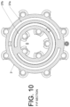
- the transmission of rotary movement to the first plate 15 is carried out by means of a planetary gear device 1 which is connected on one side to an output shaft 12a of a motor 12 (it could be electric or of any other type, also hydraulic), and on the other side, said planetary gear device 1 is connected to a shaft 14 connected to the first plate 15.
- the planetary gear device 1 comprises a fixed support 22 with an internal toothed gear 22a and a planetary assembly 29 that rotates coupled to the internal toothed gear 22a; wherein said planetary assembly 29 includes a mobile support 29a in the shape of a cross and several radial pinions 29b that rotate coupled to said mobile support 29a.
- said radial pinions 29b mesh on the one hand with the internal toothed gear 22a, and on the other hand mesh with a central pinion 30 embedded in the output shaft 12a of the motor 12; wherein said central pinion 30 also forms part of the planetary assembly 29.
- the first platform 15 includes curved-concave female front seats 15a by way of a cradle on which complementary curved-convex male front seats 17a of the second tiltable platform 17 rest; wherein the curvature of the first and the second front seats are equidistant from a shared geometric centre 46 of a crosshead mechanism 4 that will be described later.
- the linear movement of the runner 9 drags the second plate 17 by means of the connecting rod mechanism 10, so that said second plate 17 can adopt different inclinations guided in the front seats 15a of the first plate 15.
- the first plate 15 includes a centered central extension 47 on which the first axial bearing 7 is mounted with the interposition of the second internal bearing 33.
- the second plate 17 comprises second front fins 31 in parallel that include the male front seats 17a that rest on the female front seats 15a that are located in the first front fins 32 of the first plate 15; wherein the two hinged connections 10a and 10b of the crank mechanism 10 are perpendicular to the planes in which the second front fins 31 of the second plate 17 and the first front fins 32 of the first plate 15 are contained.
- the second plate 17 includes a centered extension 34 in which a second axial bearing 35 is mounted with the interposition of a second internal bearing 8, such that one of the tracks of said second axial bearing 35 is coupled on said second internal bearing 8 and this is embedded in one portion of the extension 34, while the other paired track of the second axial bearing 35 is embedded directly in another portion of the extension 34, abutting against a front seat of the second plate 17 itself.
- a ball joint support 5 On a front surface (track with the second internal bearing 8) of the second axial bearing 35 rests a first front face of a ball joint support 5 which includes, on the second front face thereof (opposite the first front face), pairs of fins 5a distributed in a circumferential contour, such that said pairs of fins 5a are coupled to end heads 3a with double joint that connect with the axial pistons 3.
- Each double joint of the end heads 3a that link the pistons 3 with the ball joint support 5 comprises a ball joint 36 coupled between pairs of fins 5a that form part of the ball joint support 5; and an intermediate joint 43 that attaches each end head 3a to the piston 3; wherein due to this intermediate joint 43 the piston 3 can rotate with respect to the respective end head 3a.
- the ball joints 36 are coupled to the pairs of fins 5a by means of shafts.
- a part 44 is attached to the piston 3, part on which the end head 3a is in turn attached by means of the intermediate joint 43 which includes a shaft.
- Said part 44 is that which enables the ball joint 36 to go up and down, but without the piston 3 being affected, i.e., this part 44 is totally guided and only has one degree of freedom, being able to move only axially accompanying the piston 3.
- crosshead mechanism 4 hinges on this second front face of the ball joint support 5, crosshead mechanism which includes two pairs of shafts; wherein a first pair of shafts 4a hinge on two aligned holes of two tabs 5b solidly attached to the ball joint support 5, while a tensioning device 13 hinges on the second pair of axes 4b of the crosshead mechanism 4.
- the tensioning device 13 comprises a support structure 48 in which two mobile collateral wings 48a are guided in parallel with curved recesses 49 in which the crosshead mechanism 4 fits/hinges by means of the second shafts 4b thereof.
- the tensioning device 13 further comprises a longitudinal axis 50 solidly attached to a central pinion 51 that meshes with two lateral pinions 52 solidly attached to two coaxial nuts coupled on two screws 53 immobilised in parallel to the two collateral wings 48a by means of the heads thereof; wherein said pinions 51, 52 are axially retained to the support structure 48.
- the longitudinal axis 50 includes a hexagonal end section 50a for being able to comfortably rotate said longitudinal shaft 50 to axially adjust said tensioning device 13 in order to axially adjust the transmission system assembly inside a prismatic main casing 19, so that during the rotation of said longitudinal axis 50 the two collateral wings 48a move axially backwards or forwards.
- the support structure 48 is screwed to an intermediate sheet 55 that forms part of the main casing 14, while it is located in parallel to and in proximity to the second end base 19b.
- annular body 56 arranged around the support structure 48 is also fixed on said intermediate sheet 55; wherein said annular body 56 includes quadrangular holes 56a in which the parts 44 solidly attached to the pistons 3 are fitted and guided in order to prevent them from rotating.
- the cross section of said parts 44 coincides with the cross section of the quadrangular holes 56a, wherein said cross sections could have any configuration other than circular to prevent the pistons 3 from rotating.
- An end part of the longitudinal axis 50 in which the hexagonal end section 50a is found is located in a hollow inside the head 2.
- the pump of the invention further includes the main casing 19 with a lateral opening that is closed by a cover 18, so that the main casing 19 has two opposing end bases: first 19a and second 19b.
- the motor 12 is fixed on the first base 19a thereof by means of first screws 38 and nuts not shown in the figures, while on the second base 19b and also outside the casing 12, a head 2 is fixed by means of second screws 39a and nuts 39b; wherein the head 2 that includes the cavities 16 in which the axial pistons 3 are guided and run.
- the entire regulable movement transmission system is housed inside the main casing 19, as well as the ball joint support 5, the transmission mechanism for moving the mobile runner 9 and the end heads 3a of the pistons 3, the tensioning device 13, as well as the rest of the elements related thereto; wherein said adjustable movement transmission system comprises the planetary gear device 1, the first plate 15, the second plate 17, as well as the other elements related thereto.
- Both the second base 19b and the intermediate sheet 55 of the main casing 19 include holes through which the pistons 3 pass to the outside, and centered holes through which the longitudinal shaft 50 of the tensioning device 13 passes.
- the first base 19a of the main casing 19 includes a centered through hole through which the output shaft 12a of the motor 12 passes inside the casing 12 to connect to the planetary gear device 1.
- each one of the cavities 16 of the pump head 2 leads into an output area that includes a first passageway 41a and a second passageway 41b in which a first check valve 40a and a second check valve 40b have been inserted; wherein the first and second passageways lead separately into a first slot 37a and into a second slot 37b.
- the pistons 3 move axially inside the cavities 16 in the forward direction to supply the fluid and in the return direction (opposite to the forward direction) to suck the fluid at least partially filling the cavities 16, to then go back to push said fluid towards the outlet and so on.
- the pistons 3 are axially guided and adjusted in holes 57a located in a front plate 57 that is screwed to a front area of the head 2 opposite to a rear area wherein the check valves 40a, 40b are found; wherein said holes 57a serve as a guide for the pistons 3, so that the movement of the pistons 3 in any other direction than the axial one, would be limited by said front plate 57 and by the annular body 56 with its quadrangular holes 56a.
- the variation of the flow rate provided by the pump of the invention at the outlet of the head 2 thereof through its first slot 37a is achieved by varying the tilt of the second plate 17, and therefore an angle ⁇ that the imaginary axis 41 of said second plate 17 forms with respect to the horizontal supports 42 of the end bases 19a, 19b of the casing 19, as shown more clearly in figure 5 .
- the variation of the tilt of the second plate 17 is achieved by moving the mobile runner 9 which is linked to said second plate 17 by means of the crank mechanism 10 and the third plate 11 coupled to the mobile runner 9 by means of an idle rotation coupling.
- the pump When the angle ⁇ is zero degrees, the pump will provide a minimum flow rate, although depending on the specific design of the pump, said flow rate could be zero, so that in this case the ball joint support 5 would be arranged in a plane perpendicular to the direction of the imaginary axis 41 of the second plate 17 and the pistons 3 would remain static without any mobility.
Landscapes
- Engineering & Computer Science (AREA)
- Mechanical Engineering (AREA)
- General Engineering & Computer Science (AREA)
- Reciprocating Pumps (AREA)
- Steroid Compounds (AREA)
Claims (17)
- Axialkolbenpumpe, die umfasst:einen statischen Kopf (2) mit parallelen Hohlräumen (16), in denen die Kolben (3) aufgenommen sind, die so ausgeführt sind, dass sie sich im Inneren der Hohlräume (16) axial in beide Richtungen bewegen, um an dem Auslass der Hohlräume (16), die auf einem Umfangsweg verteilt sind, Fluid in einer Durchflussmenge zuzuführen; sowieein regulierbares Bewegungs-Übertragungssystem, das wenigstens eine erste Drehplatte (15),eine zweite Drehplatte (17), die in Bezug auf die erste Platte (15) geneigt werden kann,sowie einen Kugelgelenk-Träger (5) enthält, wobei Enden der Kolben (3) über Endköpfe (3a) mit Doppelgelenken gekoppelt sind;- die erste Platte (15) gekrümmt-konkave, nach innen gewölbte vordere Sitze (15a) enthält, auf denen komplementäre gekrümmt-konvexe, nach außen gewölbte vordere Sitze (17a) der zweiten neigbaren Platte (17) aufliegen; wobei die Krümmung der ersten und der zweiten vorderen Sitze gleich weit von einem gemeinsamen Mittelpunkt (46) entfernt sind, der sich im Inneren eines Hauptgehäuses (19) befindet, und- der Kugelgelenk-Träger (5) frontal auf einem zweiten Axiallager (35) aufliegt, das mit einer Verlängerung (34) der zweiten Platte (17) gekoppelt ist; wobei sich der Kugelgelenk-Träger (5) ohne Drehbewegung des Kugelgelenk-Trägers stets an die Neigung der zweiten Platte (17) anpasst;das regulierbare Bewegungs-Übertragungssystem so ausgeführt ist, dass es in der Lage ist, den Hub der Kolben (3) zu variieren, um die Durchflussmenge des Fluids an dem Auslass der Hohlräume (16) zu variieren;dadurch gekennzeichnet, dassdas regulierbare Bewegungs-Übertragungssystem des Weiteren eine dritte Drehplatte (11) sowie einen beweglichen Läufer (9) mit linearer Bewegung umfasst; wobei die dritte Platte (11) mit dem beweglichen Läufer (9) mittels einer Freischaltkupplung in einer Ebene senkrecht zu der linearen Bewegung des beweglichen Läufers (9) gekoppelt ist; die erste Platte (15) die zweite Platte (17) sowie die dritte Platte (11) mit ihrer Drehung mitzieht; und wobei sich die erste Platte (15), die zweite Platte (17) und die dritte Platte (11) sowie der bewegliche Läufer (9) zusammen mit einer Spannvorrichtung (13) des Übertragungssystems im Inneren des Hauptgehäuses (19) befinden;die zweite Platte (17) mit der dritten Platte (11) mittels eines Kurbelmechanismus (10) verbunden ist, der an einem ersten Ende an der dritten Platte (11) über eine erste gelenkige Verbindung (10a) angelenkt ist, während ein zweites Ende des Kurbelmechanismus (10), das dem ersten Ende gegenüberliegt, an der zweiten Platte (17) über eine zweite gelenkige Verbindung (10b) angelenkt ist; undwobei die Veränderung des Hubs der Kolben mittels der linearen Bewegung des beweglichen Läufers (9) erfolgt, der die Neigung der zweiten Platte (17) und des Kugelgelenk-Trägers (5) über die dritte Platte (11) und den Kurbelmechanismus (10) abgewandelt.
- Axialkolbenpumpe nach Anspruch 1, dadurch gekennzeichnet, dass ein KreuzkopfMechanismus (4),der zwei Paare von Achsen enthält, an dem Kugelgelenk-Träger (5) angelenkt ist; wobei ein erstes Paar von Achsen (4a) an zwei fluchtenden Löchern zweier fest an dem Kugelgelenk-Träger (5) angebrachter Ösen (5b) angelenkt ist, während die Spannvorrichtung (13), die eine zu den Hohlräumen (16), in denen die Axialkolben (3) geführt werden und laufen parallele Längsachse (50) enthält, an dem zweiten Paar von Achsen (4b) des KreuzkopfMechanismus (4) angelenkt ist, wobei die Längsachse (50) im Inneren des Kopfes (2) geführt wird.
- Axialkolbenpumpe nach einem der vorangehenden Ansprüche, dadurch gekennzeichnet, dass die Übertragung von Drehbewegung auf die erste Platte (15) mittels einer Planetengetriebe-Vorrichtung (1) ausgeführt wird, die mit einer mit der ersten Platte (15) verbundenen Welle (14) gekoppelt ist.
- Axialkolbenpumpe nach Anspruch 3, dadurch gekennzeichnet, dass die Planetengetriebe-Vorrichtung (1) einen festen Träger (22) mit einem Innenzahnrad (22a) und eine Planetenanordnung (29) umfasst, die sich mit dem Innenzahnrad (22a) gekoppelt dreht; wobei die Planetenanordnung (29) einen beweglichen Träger (29a) in Form eines Kreuzes und mehrere radiale Ritzel (29b) umfasst, die mit dem beweglichen Träger (29a) gekoppelt frei rotieren; und wobei die radialen Ritzel (29b) einerseits mit dem Innenzahnrad (22a) kämmen und andererseits mit einem mittigen Ritzel (30) kämmen, das so ausgeführt ist, dass es eine Übertragung von Drehbewegung von außen empfängt.
- Axialkolbenpumpe nach einem der vorangehenden Ansprüche, dadurch gekennzeichnet, dass der bewegliche Läufer (9) Gewindestangen (23) enthält, die mit Ritzeln (24) gekoppelt sind, die außen mit der Außenverzahnung eines Zahnkranzes (25) kämmen; wobei eines der Ritzel (24) mit einem Zwischenritzel (26) kämmt und dieses mit einem Antriebszahnrad (27) kämmt, das fest an einer Welle angebracht ist, an der ein Stellrad (28) angebracht ist, das so konfiguriert ist, dass es die Bewegung des beweglichen Läufers (9), in Abhängigkeit von der Drehrichtung des Stellrades (28), in der einen oder der anderen Richtung ausführt; wobei alle diese verzahnten Elemente einen Regulierungsmechanismus (6) bilden, der im Inneren eines vorderen Gehäuses (21) aufgenommen ist, das mittels eines Deckels (20) geschlossen ist; wobei das vordere Gehäuse (21) und der Deckel (20) zentrierte und einander zugewandte durchgehende Hohlräume enthalten.
- Axialkolbenpumpe nach Anspruch 5, dadurch gekennzeichnet, dass das vordere Gehäuse (21) eine ringförmige Vertiefung um seinen zentrierten durchgehenden Hohlraum herum aufweist, in dem ein erstes Axiallager (7) frontal sitzt, an dem ein Abschnitt der ersten Platte (15) mit einem dazwischen angeordneten Innenlager (33) eingebettet ist, das in eine der zwei Laufbahnen des ersten Axiallagers (7) eingebettet ist, während ein anderer Abschnitt der ersten Platte (15) direkt in die andere passende Laufbahn des ersten Axiallagers (7) passt.
- Axialkolbenpumpe nach einem der vorangehenden Ansprüche, dadurch gekennzeichnet, dass die zweite Platte (17) zweite parallele Rippen (31) enthält, die die nach außen gewölbten vorderen Sitze (17a) umfassen, während die erste Platte (15) erste parallele Rippen (32) enthält, die die nach innen gewölbten vorderen Sitze (15a) einschließen; wobei die zwei gelenkigen Verbindungen (10a) und (10b) des Kurbelmechanismus (10) senkrecht zu den Ebenen sind, in denen die zweiten vorderen Flügel (31) der zweiten Platte (17) und die ersten vorderen Flügel (32) der ersten Platte (15) aufgenommen sind.
- Axialkolbenpumpe nach einem der vorangehenden Ansprüche, dadurch gekennzeichnet, dass das zweite Axiallager (35) zwei gegenüberliegende Laufbahnen umfasst, von denen eine an ein zweites Innenlager (8) gekoppelt ist und dieses in einen Abschnitt der Verlängerung (34) eingebettet ist, während die andere paarige Laufbahn des zweiten Axiallagers (35) direkt in einen anderen Abschnitt der Verlängerung (34) eingebettet ist, der an einem vorderen Sitz der zweiten Platte (17) selbst anliegt; wobei der Kugelgelenk-Träger (5) frontal auf der Laufbahn aufliegt, die an das zweite Innenlager (8) gekoppelt ist.
- Axialkolbenpumpe nach einem der vorangehenden Ansprüche, dadurch gekennzeichnet, dass jeder der Hohlräume (16) des Kopfes (2) in einen Auslassbereich führt, der einen ersten Durchlass und einen zweiten Durchlass enthält, in den ein erstes Rückschlagventil (40a) und ein zweites Rückschlagventil (40b) eingeführt worden sind; wobei der erste und der zweite Durchlass während des Ausstoßens derselben getrennt in einen ersten Fluid-Auslassschlitz (37a) und während des Ansaugens derselben in einen zweiten Fluid-Einlassschlitz (37b) führen, um die Hohlräume (16) zu füllen.
- Axialkolbenpumpe nach einem der vorangehenden Ansprüche,
dadurch gekennzeichnet, dass:- das Hauptgehäuse (19) eine seitliche Öffnung enthält, die mittels eines Deckels (18) verschlossen wird; wobei das Hauptgehäuse (19) zwei, d. h. einen ersten Endsockel (19a) und einen zweiten Endsockel (19b), aufweist, die einander gegenüberliegen;- der Kopf (2) außerhalb des Hauptgehäuses (19) und an dem zweiten Sockel (19b) befestigt ist. - Axialkolbenpumpe nach einem der vorangehenden Ansprüche, dadurch gekennzeichnet, dass jedes Doppelgelenk der Endköpfe (3a), die die Kolben (3) mit dem Kugelgelenk-Träger (5) verbinden, umfasst:- ein Kugelgelenk (36), das mittels einer Welle zwischen paarige Rippen (5a) gekoppelt ist, die Teil des Kugelgelenk-Trägers (5) sind;- ein Zwischengelenk (43), über das jeder Endkopf (3a) mittels einer weiteren Welle an dem Kolben (3) angebracht ist.
- Axialkolbenpumpe nach Anspruch 2, dadurch gekennzeichnet, dass sich der gemeinsame Mittelpunkt (46) der gekrümmt-konkaven, nach außen gewölbten vorderen Sitze (17a) der zweiten Platte (17) und der gekrümmt-konvexen, nach innen gewölbten vorderen Sitze (15a) der ersten Platte (15) in der Mitte des Kreuzkopfmechanismus (4) befindet, wobei der gemeinsame Mittelpunkt (46) von den vorderen Sitzen (15a, 17a) gleich weit entfernt ist, nachdem der Kreuzkopfmechanismus (4) vollständig positioniert und durch den Spannmechanismus (13) axial angezogen ist.
- Axialkolbenpumpe nach einem der vorangehenden Ansprüche 2 oder 12, dadurch gekennzeichnet, dass die Spannvorrichtung (13) umfasst:- eine Tragestruktur (48), in der zwei parallele seitliche Flügel (48a) mit gekrümmten Aussparungen (49) geführt werden, in denen das zweite Paar von Achsen (4b) des Kreuzkopfmechanismus (4b) angelenkt ist;- eine Längsachse (50), die fest mit einem mittigen Ritzel (51) verbunden ist, das mit zwei seitlichen Ritzel (52) kämmt, das durch Aufschrauben auf zwei Schrauben (53) gekoppelt wird, die mittels ihrer Köpfe parallel zu den zwei seitlichen Flügeln (48a) fixiert werden, wobei die Ritzel (51, 52) axial an der Tragestruktur (48) gehalten werden; und wobei die Längsachse (50) einen sechseckigen Endabschnitt (50a) enthält, um die Längsachse (50) zu drehen und die Spannvorrichtung (13) axial einzustellen, um die Übertragungssystem-Anordnung im Inneren des Hauptgehäuses (19) axial einzustellen.
- Axialkolbenpumpe nach Anspruch 13, dadurch gekennzeichnet, dass die Tragestruktur (48) der Spannvorrichtung (13) an einer Zwischenplatte (55) angeschraubt ist, die Teil des Hauptgehäuses (14) ist, wobei sie parallel zu dem zweiten Endsockel (19b) und in dessen Nähe angeordnet ist.
- Axialkolbenpumpe nach Anspruch 14, dadurch gekennzeichnet, dass ein ringförmiger Körper (56), der um die Tragestruktur (48) herum angeordnet ist, an der Zwischenplatte (55) befestigt ist; wobei der ringförmige Körper (56) viereckige Löcher (56a) enthält, in die die fest mit den Kolben (3) verbundenen Teile (44) eingepasst sind und darin geführt werden; wobei der Querschnitt der Teile (44) mit dem Durchlass-Querschnitt der viereckigen Löcher (56a) übereinstimmt.
- Axialkolbenpumpe nach den vorangehenden Ansprüchen 1 und 7, dadurch gekennzeichnet, dass die dritte Platte (11) einen äußeren Abschnitt, der von einem ringförmigen Körper (11a) gebildet wird, der durch tangentialen Kontakt mit Lagern (54) des beweglichen Läufers (9) frei rotierend punktuell gekoppelt ist, sowie einen inneren Abschnitt umfasst, der eine mittige Struktur (11b) mit Hohlräumen umfasst, in die die ersten vorderen Rippen (32) der ersten Platte (15) passen.
- Axialkolbenpumpe nach einem der vorangehenden Ansprüche, dadurch gekennzeichnet, dass die Kolben (3) in Löchern (57a) axial geführt und eingestellt werden, die sich in einer vorderen Platte (57) befinden, die in einem vorderen Bereich des Kopfes (2) gegenüber einem hinteren Bereich, in dem sich der Auslass der Hohlräume (16) befindet, angeschraubt ist; wobei die Löcher (57a) als eine Führung für die Kolben (3) dienen.
Applications Claiming Priority (2)
| Application Number | Priority Date | Filing Date | Title |
|---|---|---|---|
| ES202130892A ES2937207B2 (es) | 2021-09-23 | 2021-09-23 | Bomba de pistones axiales |
| PCT/ES2022/070364 WO2023047002A1 (es) | 2021-09-23 | 2022-06-10 | Bomba de pistones axiales |
Publications (3)
| Publication Number | Publication Date |
|---|---|
| EP4407179A1 EP4407179A1 (de) | 2024-07-31 |
| EP4407179B1 true EP4407179B1 (de) | 2024-09-25 |
| EP4407179C0 EP4407179C0 (de) | 2024-09-25 |
Family
ID=82546947
Family Applications (1)
| Application Number | Title | Priority Date | Filing Date |
|---|---|---|---|
| EP22741544.5A Active EP4407179B1 (de) | 2021-09-23 | 2022-06-10 | Axialkolbenpumpe |
Country Status (3)
| Country | Link |
|---|---|
| EP (1) | EP4407179B1 (de) |
| ES (1) | ES2937207B2 (de) |
| WO (1) | WO2023047002A1 (de) |
Family Cites Families (10)
| Publication number | Priority date | Publication date | Assignee | Title |
|---|---|---|---|---|
| GB551384A (en) * | 1941-10-07 | 1943-02-19 | Fawcett Preston & Co Ltd | Improvements in swash-plate pumps for liquids |
| FR60486E (fr) * | 1950-08-08 | 1954-11-03 | Siam | Pompe hydraulique à haute pression |
| US2737894A (en) * | 1952-08-15 | 1956-03-13 | Oilgear Co | Axial type pump with stationary cylinders |
| GB1327192A (en) * | 1969-05-21 | 1973-08-15 | Nat Res Dev | Swashplate pumps |
| DE2062184A1 (de) * | 1970-12-17 | 1972-06-22 | Maschinenfabrik Rudolf Hausherr & Söhne GmbH, 4322 Sprockhövel | Axialkolbenpumpe |
| NL7900076A (nl) * | 1979-01-05 | 1980-07-08 | Philips Nv | Drijfwerk voor een machine met heen- en weergaande zuigers met variabele slag. |
| DE3171533D1 (en) * | 1980-03-11 | 1985-09-05 | Joseph Scalzo | Wabbler plate engine mechanisms |
| JP2626292B2 (ja) * | 1991-03-30 | 1997-07-02 | 株式会社豊田自動織機製作所 | 容量可変型斜板式圧縮機 |
| EP1435457A1 (de) * | 2003-01-03 | 2004-07-07 | Lavorwash S.p.A. | Axialkolbenpumpe mit automatischer Anpassung des Durchflusses |
| ITUB20155999A1 (it) * | 2015-11-30 | 2017-05-30 | Merlo Group Innovation Lab S R L | Macchina idraulica a cilindri flottanti |
-
2021
- 2021-09-23 ES ES202130892A patent/ES2937207B2/es active Active
-
2022
- 2022-06-10 WO PCT/ES2022/070364 patent/WO2023047002A1/es not_active Ceased
- 2022-06-10 EP EP22741544.5A patent/EP4407179B1/de active Active
Also Published As
| Publication number | Publication date |
|---|---|
| ES2937207B2 (es) | 2023-07-31 |
| ES2937207A1 (es) | 2023-03-24 |
| EP4407179A1 (de) | 2024-07-31 |
| WO2023047002A1 (es) | 2023-03-30 |
| EP4407179C0 (de) | 2024-09-25 |
Similar Documents
| Publication | Publication Date | Title |
|---|---|---|
| US5211611A (en) | Planocentric drive mechanism | |
| US7588431B2 (en) | Variable capacity pump/motor | |
| US20200332782A1 (en) | Axial piston device | |
| US11661928B2 (en) | Piston pump and piston motor | |
| US20020157391A1 (en) | Pump unit | |
| EP3708833B1 (de) | Elektrische membranpumpe mit offset kulissenkurbel | |
| HUT76629A (en) | Continuously variable hydrostatic transmission | |
| US8192173B2 (en) | Pressure compensated and constant horsepower pump | |
| US7950910B2 (en) | Piston cartridge | |
| US7179070B2 (en) | Variable capacity pump/motor | |
| JPH03115782A (ja) | ラジアルピストン装置 | |
| EP0491078B1 (de) | Hydraulisches Energiegetriebe | |
| EP4407179B1 (de) | Axialkolbenpumpe | |
| EP3237754B1 (de) | Hydrostatisches pumpenfass mit abgeschrägten nierenports | |
| US20050238501A1 (en) | Revolving yoke load-sensitive displacement-varying mechanism for axial piston hydraulic pump | |
| KR100781391B1 (ko) | 구동모터를 이용한 왕복펌프 | |
| RU2612230C1 (ru) | Объемная роторно-пластинчатая машина (два варианта) | |
| EP4441365A1 (de) | Membranpumpe | |
| US20060120882A1 (en) | Motor or pump assemblies | |
| US20030206811A1 (en) | Variable displacement positive displacement pump | |
| EP1486674A1 (de) | Pumpe mit veränderlicher Verdrängung | |
| CN220726496U (zh) | 轴向活塞泵 | |
| CN223257000U (zh) | 抗倾覆高转速轴向柱塞泵 | |
| US4864916A (en) | Radial pump/motor | |
| RU2704509C1 (ru) | Гидронасос |
Legal Events
| Date | Code | Title | Description |
|---|---|---|---|
| STAA | Information on the status of an ep patent application or granted ep patent |
Free format text: STATUS: UNKNOWN |
|
| STAA | Information on the status of an ep patent application or granted ep patent |
Free format text: STATUS: THE INTERNATIONAL PUBLICATION HAS BEEN MADE |
|
| GRAP | Despatch of communication of intention to grant a patent |
Free format text: ORIGINAL CODE: EPIDOSNIGR1 |
|
| STAA | Information on the status of an ep patent application or granted ep patent |
Free format text: STATUS: GRANT OF PATENT IS INTENDED |
|
| PUAI | Public reference made under article 153(3) epc to a published international application that has entered the european phase |
Free format text: ORIGINAL CODE: 0009012 |
|
| 17P | Request for examination filed |
Effective date: 20240212 |
|
| AK | Designated contracting states |
Kind code of ref document: A1 Designated state(s): AL AT BE BG CH CY CZ DE DK EE ES FI FR GB GR HR HU IE IS IT LI LT LU LV MC MK MT NL NO PL PT RO RS SE SI SK SM TR |
|
| GRAS | Grant fee paid |
Free format text: ORIGINAL CODE: EPIDOSNIGR3 |
|
| GRAA | (expected) grant |
Free format text: ORIGINAL CODE: 0009210 |
|
| STAA | Information on the status of an ep patent application or granted ep patent |
Free format text: STATUS: THE PATENT HAS BEEN GRANTED |
|
| AK | Designated contracting states |
Kind code of ref document: B1 Designated state(s): AL AT BE BG CH CY CZ DE DK EE ES FI FR GB GR HR HU IE IS IT LI LT LU LV MC MK MT NL NO PL PT RO RS SE SI SK SM TR |
|
| REG | Reference to a national code |
Ref country code: GB Ref legal event code: FG4D |
|
| REG | Reference to a national code |
Ref country code: CH Ref legal event code: EP |
|
| REG | Reference to a national code |
Ref country code: DE Ref legal event code: R096 Ref document number: 602022006422 Country of ref document: DE |
|
| REG | Reference to a national code |
Ref country code: IE Ref legal event code: FG4D |
|
| U01 | Request for unitary effect filed |
Effective date: 20241017 |
|
| U07 | Unitary effect registered |
Designated state(s): AT BE BG DE DK EE FI FR IT LT LU LV MT NL PT RO SE SI Effective date: 20241104 |
|
| PG25 | Lapsed in a contracting state [announced via postgrant information from national office to epo] |
Ref country code: NO Free format text: LAPSE BECAUSE OF FAILURE TO SUBMIT A TRANSLATION OF THE DESCRIPTION OR TO PAY THE FEE WITHIN THE PRESCRIBED TIME-LIMIT Effective date: 20241225 |
|
| PG25 | Lapsed in a contracting state [announced via postgrant information from national office to epo] |
Ref country code: GR Free format text: LAPSE BECAUSE OF FAILURE TO SUBMIT A TRANSLATION OF THE DESCRIPTION OR TO PAY THE FEE WITHIN THE PRESCRIBED TIME-LIMIT Effective date: 20241226 |
|
| PG25 | Lapsed in a contracting state [announced via postgrant information from national office to epo] |
Ref country code: RS Free format text: LAPSE BECAUSE OF FAILURE TO SUBMIT A TRANSLATION OF THE DESCRIPTION OR TO PAY THE FEE WITHIN THE PRESCRIBED TIME-LIMIT Effective date: 20241225 |
|
| PG25 | Lapsed in a contracting state [announced via postgrant information from national office to epo] |
Ref country code: RS Free format text: LAPSE BECAUSE OF FAILURE TO SUBMIT A TRANSLATION OF THE DESCRIPTION OR TO PAY THE FEE WITHIN THE PRESCRIBED TIME-LIMIT Effective date: 20241225 Ref country code: NO Free format text: LAPSE BECAUSE OF FAILURE TO SUBMIT A TRANSLATION OF THE DESCRIPTION OR TO PAY THE FEE WITHIN THE PRESCRIBED TIME-LIMIT Effective date: 20241225 Ref country code: GR Free format text: LAPSE BECAUSE OF FAILURE TO SUBMIT A TRANSLATION OF THE DESCRIPTION OR TO PAY THE FEE WITHIN THE PRESCRIBED TIME-LIMIT Effective date: 20241226 |
|
| PG25 | Lapsed in a contracting state [announced via postgrant information from national office to epo] |
Ref country code: IS Free format text: LAPSE BECAUSE OF FAILURE TO SUBMIT A TRANSLATION OF THE DESCRIPTION OR TO PAY THE FEE WITHIN THE PRESCRIBED TIME-LIMIT Effective date: 20250125 |
|
| PG25 | Lapsed in a contracting state [announced via postgrant information from national office to epo] |
Ref country code: SM Free format text: LAPSE BECAUSE OF FAILURE TO SUBMIT A TRANSLATION OF THE DESCRIPTION OR TO PAY THE FEE WITHIN THE PRESCRIBED TIME-LIMIT Effective date: 20240925 |
|
| PG25 | Lapsed in a contracting state [announced via postgrant information from national office to epo] |
Ref country code: ES Free format text: LAPSE BECAUSE OF FAILURE TO SUBMIT A TRANSLATION OF THE DESCRIPTION OR TO PAY THE FEE WITHIN THE PRESCRIBED TIME-LIMIT Effective date: 20240925 |
|
| PG25 | Lapsed in a contracting state [announced via postgrant information from national office to epo] |
Ref country code: CZ Free format text: LAPSE BECAUSE OF FAILURE TO SUBMIT A TRANSLATION OF THE DESCRIPTION OR TO PAY THE FEE WITHIN THE PRESCRIBED TIME-LIMIT Effective date: 20240925 Ref country code: PL Free format text: LAPSE BECAUSE OF FAILURE TO SUBMIT A TRANSLATION OF THE DESCRIPTION OR TO PAY THE FEE WITHIN THE PRESCRIBED TIME-LIMIT Effective date: 20240925 |
|
| PG25 | Lapsed in a contracting state [announced via postgrant information from national office to epo] |
Ref country code: SK Free format text: LAPSE BECAUSE OF FAILURE TO SUBMIT A TRANSLATION OF THE DESCRIPTION OR TO PAY THE FEE WITHIN THE PRESCRIBED TIME-LIMIT Effective date: 20240925 |
|
| PLBE | No opposition filed within time limit |
Free format text: ORIGINAL CODE: 0009261 |
|
| STAA | Information on the status of an ep patent application or granted ep patent |
Free format text: STATUS: NO OPPOSITION FILED WITHIN TIME LIMIT |
|
| 26N | No opposition filed |
Effective date: 20250626 |
|
| PG25 | Lapsed in a contracting state [announced via postgrant information from national office to epo] |
Ref country code: HR Free format text: LAPSE BECAUSE OF FAILURE TO SUBMIT A TRANSLATION OF THE DESCRIPTION OR TO PAY THE FEE WITHIN THE PRESCRIBED TIME-LIMIT Effective date: 20240925 |
|
| REG | Reference to a national code |
Ref country code: CH Ref legal event code: H13 Free format text: ST27 STATUS EVENT CODE: U-0-0-H10-H13 (AS PROVIDED BY THE NATIONAL OFFICE) Effective date: 20260127 |
|
| PG25 | Lapsed in a contracting state [announced via postgrant information from national office to epo] |
Ref country code: MC Free format text: LAPSE BECAUSE OF FAILURE TO SUBMIT A TRANSLATION OF THE DESCRIPTION OR TO PAY THE FEE WITHIN THE PRESCRIBED TIME-LIMIT Effective date: 20240925 |