EP4407163A1 - Condensation control of steam injected turbine engine - Google Patents
Condensation control of steam injected turbine engine Download PDFInfo
- Publication number
- EP4407163A1 EP4407163A1 EP23211730.9A EP23211730A EP4407163A1 EP 4407163 A1 EP4407163 A1 EP 4407163A1 EP 23211730 A EP23211730 A EP 23211730A EP 4407163 A1 EP4407163 A1 EP 4407163A1
- Authority
- EP
- European Patent Office
- Prior art keywords
- electric machine
- spool
- turbine
- accumulation
- condensation
- Prior art date
- Legal status (The legal status is an assumption and is not a legal conclusion. Google has not performed a legal analysis and makes no representation as to the accuracy of the status listed.)
- Granted
Links
Images


Classifications
-
- F—MECHANICAL ENGINEERING; LIGHTING; HEATING; WEAPONS; BLASTING
- F02—COMBUSTION ENGINES; HOT-GAS OR COMBUSTION-PRODUCT ENGINE PLANTS
- F02C—GAS-TURBINE PLANTS; AIR INTAKES FOR JET-PROPULSION PLANTS; CONTROLLING FUEL SUPPLY IN AIR-BREATHING JET-PROPULSION PLANTS
- F02C3/00—Gas-turbine plants characterised by the use of combustion products as the working fluid
- F02C3/20—Gas-turbine plants characterised by the use of combustion products as the working fluid using a special fuel, oxidant, or dilution fluid to generate the combustion products
- F02C3/30—Adding water, steam or other fluids for influencing combustion, e.g. to obtain cleaner exhaust gases
-
- F—MECHANICAL ENGINEERING; LIGHTING; HEATING; WEAPONS; BLASTING
- F05—INDEXING SCHEMES RELATING TO ENGINES OR PUMPS IN VARIOUS SUBCLASSES OF CLASSES F01-F04
- F05D—INDEXING SCHEME FOR ASPECTS RELATING TO NON-POSITIVE-DISPLACEMENT MACHINES OR ENGINES, GAS-TURBINES OR JET-PROPULSION PLANTS
- F05D2220/00—Application
- F05D2220/70—Application in combination with
- F05D2220/76—Application in combination with an electrical generator
-
- F—MECHANICAL ENGINEERING; LIGHTING; HEATING; WEAPONS; BLASTING
- F05—INDEXING SCHEMES RELATING TO ENGINES OR PUMPS IN VARIOUS SUBCLASSES OF CLASSES F01-F04
- F05D—INDEXING SCHEME FOR ASPECTS RELATING TO NON-POSITIVE-DISPLACEMENT MACHINES OR ENGINES, GAS-TURBINES OR JET-PROPULSION PLANTS
- F05D2270/00—Control
- F05D2270/01—Purpose of the control system
- F05D2270/16—Purpose of the control system to control water or steam injection
-
- F—MECHANICAL ENGINEERING; LIGHTING; HEATING; WEAPONS; BLASTING
- F05—INDEXING SCHEMES RELATING TO ENGINES OR PUMPS IN VARIOUS SUBCLASSES OF CLASSES F01-F04
- F05D—INDEXING SCHEME FOR ASPECTS RELATING TO NON-POSITIVE-DISPLACEMENT MACHINES OR ENGINES, GAS-TURBINES OR JET-PROPULSION PLANTS
- F05D2270/00—Control
- F05D2270/30—Control parameters, e.g. input parameters
- F05D2270/311—Air humidity
Definitions
- the present disclosure relates generally to a steam injected turbine engine and more particularly to an engine including a control system that adjusts engine operation to control condensation accumulation.
- Turbine engines compress incoming core airflow, mix the compressed airflow with fuel that is ignited in a combustor to generate a high energy exhaust gas flow. Some energy in the high energy exhaust flow is recovered as it is expanded through a turbine section. Steam injection can provide improved propulsive efficiencies. Steam injection improves mass flow through the turbine section and thereby improves engine efficiency. However, the introduction of steam into a core flow may cause condensation accumulation in core engine components. Uncontrolled accumulation of condensation can affect engine performance and component life.
- Turbine engine manufacturers continue to seek further improvements to engine performance including improvements to reduce environmental impact while improving thermal and propulsive efficiencies.
- a turbine engine assembly includes a compressor section where a core flow is compressed, a combustor section where the compressed core flow is mixed with fuel and ignited to generate an exhaust gas flow, a turbine section through which the exhaust gas flow expands to generate power that is utilized to drive the compressor section, a steam injection system where water is transformed into a steam flow and communicated into the core flow, and a control system for adjusting engine operation to control accumulation of condensation.
- the control system includes a controller that is programmed to operate a control device in a variable manner to control condensation accumulation.
- the controller is programed to determine an engine operating condition that generates an accumulation of condensation above a predefined amount and operate the control device in a predefined manner to reduce or prevent the accumulation of condensation.
- the compressor section includes a first compressor and a second compressor and the turbine section includes a first turbine that is coupled to the first compressor to define a first spool and a second turbine is coupled to the second compressor to define a second spool.
- the control device includes a first electric machine that is selectively connectable to the first spool and a second electric machine that is selectively connectable to the second spool and the controller is programmed to operate the first electric machine and the second electric machine to reduce or stop condensation accumulation.
- the first electric machine and the second electric machine are electrically coupled to each other for transferring power between the first spool and the second spool.
- the controller is programmed to operate one of the first electric machine and the second electric machine as a generator to place a load on the corresponding one of the first spool and the second spool and operate the other of the first electric machine and the second electric machine as an electric motor to partially drive the other of the first spool and the second spool.
- the controller is programmed to balance power between the first spool and the second spool to maintain a turbine exit temperature within a predefined range that is determined to reduce or eliminate condensation accumulation.
- a water flow is in thermal communication with at least one of the first electric machine and the second electric machine for accepting thermal energy that is generated by at least one of the first electric machine and the second electric machine.
- a water flow is heated by one of the first electric machine and the second electric machine is communicated to an evaporator where the steam flow is generated.
- the turbine engine assembly includes a steam turbine that is driven by a steam flow upstream of the combustor.
- control device includes a variable nozzle that is upstream of the compressor section.
- the variable nozzle is operated to control inlet flow into the compressor section to maintain an engine operating parameter within a predefined range that is determined to limit condensation accumulation.
- control device includes a variable nozzle within the turbine section to control exhaust gas flow between turbine sections to maintain an engine operating parameter within a predefined range that is determined to limit condensation accumulation.
- An aircraft propulsion system includes a first spool that includes a first compressor section that is coupled to a first turbine section, a second spool includes a second compressor section that is coupled to a second turbine section.
- the aircraft propulsion system includes a combustor section where a compressed core flow is mixed with fuel and ignited to generate an exhaust gas flow, a cryogenic fuel system that supplies a cryogenic fuel to the combustor through a fuel flow path, a water recovery system where water from the exhaust gas flow is recovered, a steam injection system where recovered water is transformed into a steam flow and communicated into the core flow, and a control system for adjusting engine operation to control an accumulation of condensation.
- the control system includes a control device and a controller that is programmed to operate the control device conditions indicative of an accumulation of condensation and to operate the control device to reduce or prevent the accumulation of condensation.
- the control device includes a first electric machine that is mechanically coupled to the first spool and a second electric machine that is mechanically coupled to the second spool, the first electric machine and the second electric machine are electrically coupled to each other for transferring power between the first spool and the second spool and the controller is programmed to operate one of the first electric machine and the second electric machine as a generator to place a load on the corresponding one of the first spool and the second spool and operate the other of the first electric machine and the second electric machine as an electric motor to partially drive the other of the first spool and the second spool.
- a water flow is heated by one of the first electric machine and the second electric machine is communicated to an evaporator where a steam flow is generated.
- the aircraft propulsion system includes a steam turbine that is driven by a steam flow that is upstream of the combustor and downstream of the evaporator.
- control device includes a variable nozzle that is operated to control inlet flow into at least one of the first compressor section and the second compressor section to maintain an engine operating parameter within a predefined range that is determined to limit condensation accumulation.
- control device includes a variable nozzle within a turbine section to control exhaust gas flow into at least one of the first turbine section and the second turbine section.
- a method of controlling condensation accumulation in a steam injected turbine engine aspect of the present invention includes monitoring an engine operating condition that is indicative of an accumulation of condensation, and adjusting a variable control device that utilizes a controller that is programmed to operate the variable control device based on the monitored engine operating condition to reduce or prevent the accumulation of condensation.
- the variable control device includes a first electric machine that is mechanically coupled to a first spool and a second electric machine that is mechanically coupled to a second spool, the first electric machine and the second electric machine are electrically coupled to each other and the method further includes transferring electric power between the first spool and the second spool by operating one of the first electric machine and the second electric machine as a generator to place a load on the corresponding one of the first spool and the second spool and operating the other of the first electric machine and the second electric machine as an electric motor to partially drive the other of the first spool and the second spool.
- control device includes a variable nozzle that is operated to control inlet flow into compressor section and the controller operates the variable nozzle to change the inlet flow based on the monitored engine operating condition to maintain an engine operating parameter within a predefined range determined to limit condensation accumulation.
- control device includes a variable nozzle within a turbine section to control exhaust gas flow into the turbine section and the controller operates the variable nozzle to maintain an engine operating parameter within a predefined range that is determined to limit condensation accumulation.
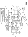
- Figure 1 schematically illustrates an engine 20 wherein steam is injected into the core flow path to increase mass flow through a turbine section 28 and thereby provide increased power without additional work from a compressor section 24. Uncontrolled accumulation of condensation from water in the exhaust gas flow can reduce engine efficiency and decrease part durability.
- the example turbine engine 20 includes a control system 30 that adjusts a variable control device to tailor engine operation to reduce or prevent condensation accumulation.
- the engine 20 includes a fan section 22, the compressor section 24, a combustor section 26 and the turbine section 28 disposed serially along an engine axis A.
- the fan section 22 drives inlet airflow 18 into a bypass flow path B and a core flow path C.
- a core flow 38 is compressed and communicated to a combustor section 26.
- the compressed core airflow is mixed with a fuel flow 78 and ignited to generate the high energy combusted exhaust gas flow 64 that expands through the turbine section 28 where energy is extracted and utilized to drive the fan section 22 and the compressor section 24 before being exhausted through nozzle 36.
- the engine 20 includes a fuel system 32 that includes a fuel tank 74 and a fuel pump 76 for generating the fuel flow 78.
- the example fuel system 32 is configured to provide a hydrogen based fuel such as a liquid hydrogen (LH 2 ).
- a hydrogen based fuel such as a liquid hydrogen (LH 2 ).
- LH 2 liquid hydrogen
- hydrogen is disclosed by way of example, other non-carbon based fuels could be utilized and are within the contemplation of this disclosure.
- the disclosed features may also be beneficial in an engine configured to operate with traditional carbon based fuels.
- the example engine 20 includes the compressor section 24 with a low pressure compressor (LPC) 42 and a high pressure compressor (HPC) 44.
- the LPC 42 may also be referred to as a first compressor and the HPC 44 may be referred to as a second compressor.
- the turbine section 28 includes a low pressure turbine (LPT) 48 and a high pressure turbine (HPT) 46.
- the LPT 48 may also be referred to as a first turbine and the HPT 46 may also be referred to as a second turbine.
- the LPC 42 is coupled to the LPT 48 though a first shaft 52 to define a low or first spool 56.
- the HPC 44 is couple to the HPT 46 through a second shaft 50 to define a high or second spool 54. It should be appreciated, that other turbine section configurations could be utilized and remain within the scope and contemplation of this disclosure.
- An evaporator 58 is disposed along the engine axis A aft of the LPT 48.
- heat from the exhaust gas flow 64 is utilized to transform a water flow 66 into a steam flow 68.
- the steam flow 68 is then communicated into the core flow 38.
- the steam flow 68 is injected into the combustor 26.
- the steam flow 68 may be injected within the core flow path C upstream of the combustor 26.
- the water flow 66 is provided by a condenser 60 that draws water out of the exhaust gas flow 64.
- a cooling flow such as a portion of the bypass air flow 40 cools the exhaust gas flow 64 in the condenser 60 to recovery water 66.
- the water is communicated to a storage tank 70.
- a pump 72 provides a pressurized water flow 66 to the evaporator for generation of steam 68.
- the bypass air flow 40 is shown by way of example as the cooling medium used to condense water from the exhaust gas flow 64, other cooling mediums, such as fuel, could be utilized and are within the contemplation of this disclosure.
- the steam flow 68 increases mass flow through the turbine section 28 and thereby increases engine power and efficiency.
- the engine 20 has an increased power output from the injected steam 68 due to an increasing mass flow through the turbine section 28 without a corresponding increase in work from the compressor section 24.
- An example engine operation cycle may include up to (or more than) 35% steam-air-ratios (SAR) and may be assisted by a multiple fold (e.g., 2x, 3x, etc.) increase in moisture from burning H 2 as the fuel.
- SAR steam-air-ratios
- a steam turbine 62 may receive a portion of the steam flow 68 to capture additional waste energy and generate shaft power.
- the steam turbine 62 may be connected to drive any engine accessory component or gearbox.
- the input of the steam flow 68 into the core flow along with the use of hydrogen based fuels can result in the accumulation of condensation throughout the engine 20. Condensation may build up anywhere within the core flow path C, including just aft of the turbine section as indicated at 100, and/or proximate the steam turbine 102. While some portions of the engine 20 may not be adversely affected by the buildup of condensation, other sections may encounter reduced component operational efficiency and durability. Accordingly, the example engine 20 includes the control system 30 for controlling the accumulation of condensation.
- the engine 20 includes a first electric machine 80 electrically coupled to a second electric machine 82.
- Each of the first and second electric machines 82, 80 can operate as either an electric generator or an electric motor.
- the first electric machine 80 is coupled through a first mechanical link 94 to the first spool 56.
- the first link 94 is coupled to the first shaft 52.
- the second electric machine is coupled though a second mechanical link 96 to the second spool 54.
- the second link 96 is coupled to the second shaft 50 of the second spool 54.
- the first link 94 and the second link 96 may include any combination of gear, shaft and mechanical coupling to transfer torque and power between the corresponding shafts 50, 52 and machines 80, 82.
- the first and second electric machines 80, 82 are actuated by a controller 84 to maintain engine operation within a predefined range determined to reduce and/or eliminate condensation build up.
- the controller 84 may, for example, operate the first and second electric machines to balance loads between the first and second spools 54, 56 to maintain a desired overall pressure ratio (OPR) that maintains reduces condensation generation to within acceptable limits.
- OPR overall pressure ratio
- the disclosed example controller 84 may include a device and system for performing necessary computing or calculation operations.
- the controller 84 may be specially constructed for this purpose, or it may comprise a portion of an engine or aircraft controller that includes operating instructions for directing operation of the engine control devices based on information indicative of the accumulation of condensation within the engine 20.
- the controller 84 is programmed to determine an engine operating condition from various aircraft sensors, systems and controllers schematically indicated at 90 based on predefined and stored information.
- the controller 84 is further programmed to operate the electric machines 80, 82 to prevent the accumulation of condensation.
- controller 84 is programmed to operate first electric machine 80 as a generator to place a load on the he first spool 56.
- the controller 84 operates the second electric machine 82 as an electric motor that receives electric power 92 from the first electric machine 80 to partially drive the second spool 54.
- the controller 84 may operate the second electric machine 82 as a generator to place a load on the second spool 54 and operate the first electric machine 80 as an electric motor to partially drive the first spool 56.
- the controller 84 is programmed to balance power between the first spool 54 and the second spool 56 to maintain engine operation within predefined operating parameters that prevent and/or eliminate condensation accumulation.
- the controller 84 is programmed to maintain a turbine exit temperature within a predefined range that is determined to reduce or eliminate condensation accumulation.
- the OPR is utilized as an indicator of condensation accumulation and maintained within a predefined range.
- FIG. 2 another example engine embodiment is generally indicated at 120 and includes features for recovering thermal energy in the form of waste heat generated by the first and second electric machines 80, 82.
- a water flow 86 is communicated to one of a first heat exchanger 104 and a second heat exchanger 106 associated with a corresponding one of the first and second electric machines 80, 82.
- the cooling water flow 86 is heated by thermal energy generated at the corresponding electric machine 80, 82.
- the heated water flow 88 is than communicated to the evaporator 58 for transformation into the steam flow 68.
- the cooling water flow 86 and the heated water flow 88 may be selectively communicated to both or individually to each of the first and second electric machines 80, 82.
- Thermal energy recovered from operation of the electric machines 80, 82 is input back into the engine 120 in the form of the steam flow 68 injected into the combustor 26. Additionally, thermal energy may be recovered in the form of shaft power generated by the steam turbine 62.
- the engine 220 includes variable features that tailor engine operation based on information indictive of condensation accumulation outside predefined ranges.
- the engine 220 includes a first variable nozzle 122 that adjusts inlet flow 18 into the compressor section 24 and thereby into the core flow path C. Adjustment of inlet airflow 18 into the core flow path C can be utilized to control an OPR, exit temperatures for the compressor section 24, exit temperature of the turbine section 28 as well as other engine operating parameters that effect condensation accumulation.
- the first variable nozzle 122 may be of any structure or configuration that provides control over inlet flow into the core flow path C. The variable nozzle 122, may only partially close off inlet flows 18 to provide small changes that control condensation accumulation.
- a second variable flow control nozzle 124 is shown within the turbine section 28.
- the second flow control nozzle 124 provides control of flows through the turbine sections 46, 48.
- the control nozzle 124 may only partially restrict exhaust flows through the turbine section an amount that provides sufficient changes to control and/or prevent condensation accumulation.
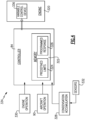
- the example control system 334 includes the controller 84 that is in control communication with a variable control device 336 of a turbine engine that is schematically indicated at 320.
- the controller 84 includes a memory device 322 with information indicative of predefined engine operating limits, schematically shown at 324, corresponding to condensation accumulation.
- the memory device 322 further includes information regarding a predefined programed response, schematically shown at 326.
- the controller 84 receives information indicative of engine operation 330, aircraft operation 90 and condensation accumulation 328.
- Information on condensation accumulation 328 may be ascertained from other engine operating parameters that are indictive of condensation accumulation or direct information from sensors 332 that collect information on condensation accumulation.
- the sensors 332 may directly detect condensation accumulation or information that would indicate the accumulation of condensation based on other information and measurements.
- the controller 84 uses the information regarding engine operation 330, aircraft operation 90 and condensation information 328 to control a variable control device schematically shown at 336.
- the variable control device 336 may be an engine operating control such as fuel valve to control a fuel flow to the combustor, a variable area nozzle controlling inlet airflow, a variable turbine, a variable outlet nozzle or any other variable control components.
- the variable control device 336 may be associated with the water recovery and steam generation such as valving to limit water recovery and/or steam generation in response to information that is indicative of condensation accumulation.
- the example disclosed engine and control system embodiments provide controls to reduce or prevent the accumulation of condensation during engine operation.
Landscapes
- Engineering & Computer Science (AREA)
- Chemical & Material Sciences (AREA)
- Combustion & Propulsion (AREA)
- Mechanical Engineering (AREA)
- General Engineering & Computer Science (AREA)
- Control Of Turbines (AREA)
- Engine Equipment That Uses Special Cycles (AREA)
Abstract
Description
- The present disclosure relates generally to a steam injected turbine engine and more particularly to an engine including a control system that adjusts engine operation to control condensation accumulation.
- Reduction and/or elimination of carbon emissions generated by aircraft operation is a stated goal of aircraft manufacturers and airline operators. Turbine engines compress incoming core airflow, mix the compressed airflow with fuel that is ignited in a combustor to generate a high energy exhaust gas flow. Some energy in the high energy exhaust flow is recovered as it is expanded through a turbine section. Steam injection can provide improved propulsive efficiencies. Steam injection improves mass flow through the turbine section and thereby improves engine efficiency. However, the introduction of steam into a core flow may cause condensation accumulation in core engine components. Uncontrolled accumulation of condensation can affect engine performance and component life.
- Turbine engine manufacturers continue to seek further improvements to engine performance including improvements to reduce environmental impact while improving thermal and propulsive efficiencies.
- A turbine engine assembly according to an aspect of the present invention includes a compressor section where a core flow is compressed, a combustor section where the compressed core flow is mixed with fuel and ignited to generate an exhaust gas flow, a turbine section through which the exhaust gas flow expands to generate power that is utilized to drive the compressor section, a steam injection system where water is transformed into a steam flow and communicated into the core flow, and a control system for adjusting engine operation to control accumulation of condensation. The control system includes a controller that is programmed to operate a control device in a variable manner to control condensation accumulation.
- In an embodiment of the foregoing turbine engine assembly, the controller is programed to determine an engine operating condition that generates an accumulation of condensation above a predefined amount and operate the control device in a predefined manner to reduce or prevent the accumulation of condensation.
- In a further embodiment of any of the foregoing turbine engine assemblies, the compressor section includes a first compressor and a second compressor and the turbine section includes a first turbine that is coupled to the first compressor to define a first spool and a second turbine is coupled to the second compressor to define a second spool. The control device includes a first electric machine that is selectively connectable to the first spool and a second electric machine that is selectively connectable to the second spool and the controller is programmed to operate the first electric machine and the second electric machine to reduce or stop condensation accumulation.
- In a further embodiment of any of the foregoing turbine engine assemblies, the first electric machine and the second electric machine are electrically coupled to each other for transferring power between the first spool and the second spool.
- In a further embodiment of any of the foregoing turbine engine assemblies, the controller is programmed to operate one of the first electric machine and the second electric machine as a generator to place a load on the corresponding one of the first spool and the second spool and operate the other of the first electric machine and the second electric machine as an electric motor to partially drive the other of the first spool and the second spool.
- In a further embodiment of any of the foregoing turbine engine assemblies, the controller is programmed to balance power between the first spool and the second spool to maintain a turbine exit temperature within a predefined range that is determined to reduce or eliminate condensation accumulation.
- In a further embodiment of any of the foregoing turbine engine assemblies, a water flow is in thermal communication with at least one of the first electric machine and the second electric machine for accepting thermal energy that is generated by at least one of the first electric machine and the second electric machine.
- In a further embodiment of any of the foregoing turbine engine assemblies, a water flow is heated by one of the first electric machine and the second electric machine is communicated to an evaporator where the steam flow is generated.
- In a further embodiment of any of the foregoing turbine engine assemblies, the turbine engine assembly includes a steam turbine that is driven by a steam flow upstream of the combustor.
- In a further embodiment of any of the foregoing turbine engine assemblies, the control device includes a variable nozzle that is upstream of the compressor section. The variable nozzle is operated to control inlet flow into the compressor section to maintain an engine operating parameter within a predefined range that is determined to limit condensation accumulation.
- In a further embodiment of any of the foregoing turbine engine assemblies, the control device includes a variable nozzle within the turbine section to control exhaust gas flow between turbine sections to maintain an engine operating parameter within a predefined range that is determined to limit condensation accumulation.
- An aircraft propulsion system according to another aspect of the present invention includes a first spool that includes a first compressor section that is coupled to a first turbine section, a second spool includes a second compressor section that is coupled to a second turbine section. The aircraft propulsion system includes a combustor section where a compressed core flow is mixed with fuel and ignited to generate an exhaust gas flow, a cryogenic fuel system that supplies a cryogenic fuel to the combustor through a fuel flow path, a water recovery system where water from the exhaust gas flow is recovered, a steam injection system where recovered water is transformed into a steam flow and communicated into the core flow, and a control system for adjusting engine operation to control an accumulation of condensation. The control system includes a control device and a controller that is programmed to operate the control device conditions indicative of an accumulation of condensation and to operate the control device to reduce or prevent the accumulation of condensation.
- In an embodiment of the foregoing aircraft propulsion system, the control device includes a first electric machine that is mechanically coupled to the first spool and a second electric machine that is mechanically coupled to the second spool, the first electric machine and the second electric machine are electrically coupled to each other for transferring power between the first spool and the second spool and the controller is programmed to operate one of the first electric machine and the second electric machine as a generator to place a load on the corresponding one of the first spool and the second spool and operate the other of the first electric machine and the second electric machine as an electric motor to partially drive the other of the first spool and the second spool.
- In a further embodiment of any of the foregoing aircraft propulsion systems, a water flow is heated by one of the first electric machine and the second electric machine is communicated to an evaporator where a steam flow is generated.
- In a further embodiment of any of the foregoing aircraft propulsion systems, the aircraft propulsion system includes a steam turbine that is driven by a steam flow that is upstream of the combustor and downstream of the evaporator.
- In a further embodiment of any of the foregoing aircraft propulsion systems, the control device includes a variable nozzle that is operated to control inlet flow into at least one of the first compressor section and the second compressor section to maintain an engine operating parameter within a predefined range that is determined to limit condensation accumulation.
- In a further embodiment of any of the foregoing aircraft propulsion systems, the control device includes a variable nozzle within a turbine section to control exhaust gas flow into at least one of the first turbine section and the second turbine section.
- A method of controlling condensation accumulation in a steam injected turbine engine aspect of the present invention includes monitoring an engine operating condition that is indicative of an accumulation of condensation, and adjusting a variable control device that utilizes a controller that is programmed to operate the variable control device based on the monitored engine operating condition to reduce or prevent the accumulation of condensation.
- In an sembodiment of the foregoing method, the variable control device includes a first electric machine that is mechanically coupled to a first spool and a second electric machine that is mechanically coupled to a second spool, the first electric machine and the second electric machine are electrically coupled to each other and the method further includes transferring electric power between the first spool and the second spool by operating one of the first electric machine and the second electric machine as a generator to place a load on the corresponding one of the first spool and the second spool and operating the other of the first electric machine and the second electric machine as an electric motor to partially drive the other of the first spool and the second spool.
- In a further embodiment of any of the foregoing methods, the control device includes a variable nozzle that is operated to control inlet flow into compressor section and the controller operates the variable nozzle to change the inlet flow based on the monitored engine operating condition to maintain an engine operating parameter within a predefined range determined to limit condensation accumulation.
- In a further embodiment of any of the foregoing methods, the control device includes a variable nozzle within a turbine section to control exhaust gas flow into the turbine section and the controller operates the variable nozzle to maintain an engine operating parameter within a predefined range that is determined to limit condensation accumulation.
- Although the different examples have the specific components shown in the illustrations, embodiments of this invention are not limited to those particular combinations. It is possible to use some of the components or features from one of the examples in combination with features or components from another one of the examples.
- These and other features disclosed herein can be best understood from the following specification and drawings, the following of which is a brief description.
-
-
Figure 1 is a schematic view of an example turbine engine and control system embodiment. -
Figure 2 is a schematic view of another example turbine engine and control system embodiment. -
Figure 3 is a schematic view of another example turbine engine and control system embodiment. -
Figure 4 is a schematic view of an example control system embodiment for control condensation accumulation. -
Figure 1 schematically illustrates anengine 20 wherein steam is injected into the core flow path to increase mass flow through aturbine section 28 and thereby provide increased power without additional work from acompressor section 24. Uncontrolled accumulation of condensation from water in the exhaust gas flow can reduce engine efficiency and decrease part durability. Theexample turbine engine 20 includes acontrol system 30 that adjusts a variable control device to tailor engine operation to reduce or prevent condensation accumulation. - The
engine 20 includes afan section 22, thecompressor section 24, acombustor section 26 and theturbine section 28 disposed serially along an engine axis A. Thefan section 22 drivesinlet airflow 18 into a bypass flow path B and a core flow path C. In thecompressor section 24, acore flow 38 is compressed and communicated to acombustor section 26. In thecombustor section 26, the compressed core airflow is mixed with a fuel flow 78 and ignited to generate the high energy combustedexhaust gas flow 64 that expands through theturbine section 28 where energy is extracted and utilized to drive thefan section 22 and thecompressor section 24 before being exhausted throughnozzle 36. - The
engine 20 includes afuel system 32 that includes afuel tank 74 and afuel pump 76 for generating the fuel flow 78. Theexample fuel system 32 is configured to provide a hydrogen based fuel such as a liquid hydrogen (LH2). Although hydrogen is disclosed by way of example, other non-carbon based fuels could be utilized and are within the contemplation of this disclosure. Moreover, the disclosed features may also be beneficial in an engine configured to operate with traditional carbon based fuels. - The
example engine 20 includes thecompressor section 24 with a low pressure compressor (LPC) 42 and a high pressure compressor (HPC) 44. TheLPC 42 may also be referred to as a first compressor and the HPC 44 may be referred to as a second compressor. Theturbine section 28 includes a low pressure turbine (LPT) 48 and a high pressure turbine (HPT) 46. TheLPT 48 may also be referred to as a first turbine and the HPT 46 may also be referred to as a second turbine. - The
LPC 42 is coupled to theLPT 48 though afirst shaft 52 to define a low orfirst spool 56. The HPC 44 is couple to the HPT 46 through asecond shaft 50 to define a high orsecond spool 54. It should be appreciated, that other turbine section configurations could be utilized and remain within the scope and contemplation of this disclosure. - An
evaporator 58 is disposed along the engine axis A aft of theLPT 48. In theevaporator 58, heat from theexhaust gas flow 64 is utilized to transform awater flow 66 into asteam flow 68. Thesteam flow 68 is then communicated into thecore flow 38. In one disclosed example embodiment, thesteam flow 68 is injected into thecombustor 26. However, thesteam flow 68 may be injected within the core flow path C upstream of thecombustor 26. - The
water flow 66 is provided by acondenser 60 that draws water out of theexhaust gas flow 64. A cooling flow, such as a portion of thebypass air flow 40 cools theexhaust gas flow 64 in thecondenser 60 torecovery water 66. The water is communicated to astorage tank 70. Apump 72 provides apressurized water flow 66 to the evaporator for generation ofsteam 68. Although thebypass air flow 40 is shown by way of example as the cooling medium used to condense water from theexhaust gas flow 64, other cooling mediums, such as fuel, could be utilized and are within the contemplation of this disclosure. - The
steam flow 68 increases mass flow through theturbine section 28 and thereby increases engine power and efficiency. Theengine 20 has an increased power output from the injectedsteam 68 due to an increasing mass flow through theturbine section 28 without a corresponding increase in work from thecompressor section 24. An example engine operation cycle may include up to (or more than) 35% steam-air-ratios (SAR) and may be assisted by a multiple fold (e.g., 2x, 3x, etc.) increase in moisture from burning H2 as the fuel. - A
steam turbine 62 may receive a portion of thesteam flow 68 to capture additional waste energy and generate shaft power. Thesteam turbine 62 may be connected to drive any engine accessory component or gearbox. - The input of the
steam flow 68 into the core flow along with the use of hydrogen based fuels can result in the accumulation of condensation throughout theengine 20. Condensation may build up anywhere within the core flow path C, including just aft of the turbine section as indicated at 100, and/or proximate thesteam turbine 102. While some portions of theengine 20 may not be adversely affected by the buildup of condensation, other sections may encounter reduced component operational efficiency and durability. Accordingly, theexample engine 20 includes thecontrol system 30 for controlling the accumulation of condensation. - The
engine 20 includes a firstelectric machine 80 electrically coupled to a secondelectric machine 82. Each of the first and secondelectric machines electric machine 80 is coupled through a firstmechanical link 94 to thefirst spool 56. In one example embodiment, thefirst link 94 is coupled to thefirst shaft 52. The second electric machine is coupled though a secondmechanical link 96 to thesecond spool 54. In one example embodiment, thesecond link 96 is coupled to thesecond shaft 50 of thesecond spool 54. Thefirst link 94 and thesecond link 96 may include any combination of gear, shaft and mechanical coupling to transfer torque and power between the correspondingshafts machines - The first and second
electric machines controller 84 to maintain engine operation within a predefined range determined to reduce and/or eliminate condensation build up. Thecontroller 84, may, for example, operate the first and second electric machines to balance loads between the first andsecond spools - The disclosed
example controller 84 may include a device and system for performing necessary computing or calculation operations. Thecontroller 84 may be specially constructed for this purpose, or it may comprise a portion of an engine or aircraft controller that includes operating instructions for directing operation of the engine control devices based on information indicative of the accumulation of condensation within theengine 20. - In one example embodiment, the
controller 84 is programmed to determine an engine operating condition from various aircraft sensors, systems and controllers schematically indicated at 90 based on predefined and stored information. Thecontroller 84 is further programmed to operate theelectric machines - In one disclosed example embodiment, to
controller 84 is programmed to operate firstelectric machine 80 as a generator to place a load on the hefirst spool 56. Thecontroller 84 operates the secondelectric machine 82 as an electric motor that receives electric power 92 from the firstelectric machine 80 to partially drive thesecond spool 54. - Alternatively, the
controller 84 may operate the secondelectric machine 82 as a generator to place a load on thesecond spool 54 and operate the firstelectric machine 80 as an electric motor to partially drive thefirst spool 56. In each example operation conditions, thecontroller 84 is programmed to balance power between thefirst spool 54 and thesecond spool 56 to maintain engine operation within predefined operating parameters that prevent and/or eliminate condensation accumulation. - In one example embodiment, the
controller 84 is programmed to maintain a turbine exit temperature within a predefined range that is determined to reduce or eliminate condensation accumulation. In another example embodiment, the OPR is utilized as an indicator of condensation accumulation and maintained within a predefined range. Moreover, although individual engine operating parameters are disclosed and discussed by way of example, many different individual and combination of factors and engine operating parameters that are indicative of possible condensation accumulation could be utilized and are within the contemplation of this disclosure. - Moreover, although the locations of possible condensation accumulation are shown at 100 and 102 by way of example, other location within the engine may also warrant efforts to avoid and/or prevent condensation accumulation.
- Referring to
Figure 2 , another example engine embodiment is generally indicated at 120 and includes features for recovering thermal energy in the form of waste heat generated by the first and secondelectric machines water flow 86 is communicated to one of afirst heat exchanger 104 and asecond heat exchanger 106 associated with a corresponding one of the first and secondelectric machines water flow 86 is heated by thermal energy generated at the correspondingelectric machine heated water flow 88 is than communicated to theevaporator 58 for transformation into thesteam flow 68. As appreciated, the coolingwater flow 86 and theheated water flow 88 may be selectively communicated to both or individually to each of the first and secondelectric machines electric machines engine 120 in the form of thesteam flow 68 injected into thecombustor 26. Additionally, thermal energy may be recovered in the form of shaft power generated by thesteam turbine 62. - Referring to
Figure 3 , another example engine embodiment is schematically shown and indicated at 220. Theengine 220 includes variable features that tailor engine operation based on information indictive of condensation accumulation outside predefined ranges. Theengine 220 includes a firstvariable nozzle 122 that adjustsinlet flow 18 into thecompressor section 24 and thereby into the core flow path C. Adjustment ofinlet airflow 18 into the core flow path C can be utilized to control an OPR, exit temperatures for thecompressor section 24, exit temperature of theturbine section 28 as well as other engine operating parameters that effect condensation accumulation. The firstvariable nozzle 122 may be of any structure or configuration that provides control over inlet flow into the core flow path C. Thevariable nozzle 122, may only partially close off inlet flows 18 to provide small changes that control condensation accumulation. - A second variable
flow control nozzle 124 is shown within theturbine section 28. In this example, the secondflow control nozzle 124 provides control of flows through theturbine sections control nozzle 124 may only partially restrict exhaust flows through the turbine section an amount that provides sufficient changes to control and/or prevent condensation accumulation. - Referring to
Figure 4 , an example variable control system is schematically shown and indicated at 334. Theexample control system 334 includes thecontroller 84 that is in control communication with avariable control device 336 of a turbine engine that is schematically indicated at 320. Thecontroller 84 includes amemory device 322 with information indicative of predefined engine operating limits, schematically shown at 324, corresponding to condensation accumulation. Thememory device 322 further includes information regarding a predefined programed response, schematically shown at 326. Thecontroller 84 receives information indicative ofengine operation 330,aircraft operation 90 andcondensation accumulation 328. Information oncondensation accumulation 328 may be ascertained from other engine operating parameters that are indictive of condensation accumulation or direct information fromsensors 332 that collect information on condensation accumulation. Thesensors 332 may directly detect condensation accumulation or information that would indicate the accumulation of condensation based on other information and measurements. - The
controller 84 uses the information regardingengine operation 330,aircraft operation 90 andcondensation information 328 to control a variable control device schematically shown at 336. Thevariable control device 336 may be an engine operating control such as fuel valve to control a fuel flow to the combustor, a variable area nozzle controlling inlet airflow, a variable turbine, a variable outlet nozzle or any other variable control components. Moreover, thevariable control device 336 may be associated with the water recovery and steam generation such as valving to limit water recovery and/or steam generation in response to information that is indicative of condensation accumulation. - Accordingly, the example disclosed engine and control system embodiments provide controls to reduce or prevent the accumulation of condensation during engine operation.
- Although an example embodiment has been disclosed, a worker of ordinary skill in this art would recognize that certain modifications would come within the scope of this disclosure. For that reason, the following claims should be studied to determine the scope and content of this disclosure.
Claims (15)
- A turbine engine assembly (20; 120; 220) comprising:a compressor section (24) where a core flow (38) is compressed;a combustor section (26) where the compressed core flow (38) is mixed with fuel and ignited to generate an exhaust gas flow (64);a turbine section (28) through which the exhaust gas flow (64) expands to generate power utilized to drive the compressor section (24);a steam injection system where water (66) is transformed into a steam flow (68) and communicated into the core flow (38); anda control system (30; 334) for adjusting engine operation (330) to control accumulation of condensation, the control system (30; 334) including a controller (84) programmed to operate a control device (80, 82; 122, 124; 336) in a variable manner to control condensation accumulation.
- The turbine engine assembly (20; 120; 220) as recited in claim 1, wherein the controller (84) is programed to determine an engine operating condition that generates an accumulation of condensation above a predefined amount and operate the control device (80...336) in a predefined manner to reduce or prevent the accumulation of condensation.
- The turbine engine assembly (20; 120; 220) as recited in claim 1 or 2, wherein the compressor section (24) includes a first compressor (42) and a second compressor (44) and the turbine section (28) includes a first turbine (48) coupled to the first compressor (42) to define a first spool (56) and a second turbine (46) is coupled to the second compressor (44) to define a second spool (54), the control device (80...336) comprises a first electric machine (80) selectively connectable to the first spool (56) and a second electric machine (82) selectively connectable to the second spool (54) and the controller (84) is programmed to operate the first electric machine (80) and the second electric machine (82) to reduce or stop condensation accumulation.
- The turbine engine assembly (20; 120; 220) as recited in claim 3, wherein the first electric machine (80) and the second electric machine (82) are electrically coupled to each other for transferring power between the first spool (56) and the second spool (54).
- The turbine engine assembly (20; 120; 220) as recited in claim 4, wherein the controller (84) is programmed to operate one of the first electric machine (80) and the second electric machine (82) as a generator to place a load on the corresponding one of the first spool (56) and the second spool (54) and operate the other of the first electric machine (80) and the second electric machine (82) as an electric motor to partially drive the other of the first spool (56) and the second spool (54).
- The turbine engine assembly (20; 120; 220) as recited in claim 4 or 5, wherein the controller (84) is programmed to balance power between the first spool (56) and the second spool (54) to maintain a turbine exit temperature within a predefined range that is determined to reduce or eliminate condensation accumulation.
- The turbine engine assembly (120) as recited in any of claims 3 to 6, wherein a water flow (86) is in thermal communication with at least one of the first electric machine (80) and the second electric machine (82) for accepting thermal energy generated by at least one of the first electric machine (80) and the second electric machine (82).
- The turbine engine assembly (120) as recited in claim 7, wherein a water flow (88) heated by one of the first electric machine (80) and the second electric machine (82) is communicated to an evaporator (58) where the steam flow (68) is generated.
- The turbine engine assembly (20; 120; 220) as recited in any preceding claim, including a steam turbine (62) driven by a steam flow (68) upstream of the combustor (26).
- The turbine engine assembly (220) as recited in any preceding claim, wherein the control device (80...336) comprises a variable nozzle (122) upstream of the compressor section (24), the variable nozzle (122) operated to control inlet flow (18) into the compressor section (24) to maintain an engine operating parameter within a predefined range determined to limit condensation accumulation, and/or wherein the control device (80...336) comprises a variable nozzle (124) within the turbine section (28) to control exhaust gas flow (64) between turbines (46, 48) to maintain an engine operating parameter within a predefined range determined to limit condensation accumulation.
- The turbine engine assembly (20; 120; 220) of any preceding claim, further comprising a cryogenic fuel system (32) for supplying a cryogenic fuel to the combustor (26) through a fuel flow path, and a water recovery system where water (66) from the exhaust gas flow (64) is recovered.
- A method of controlling condensation accumulation in a steam injected turbine engine (20; 120; 220), the method comprising:monitoring an engine operating condition indicative of an accumulation of condensation; andadjusting a variable control device (80, 82; 122, 124; 336) utilizing a controller (84) programmed to operate the variable control device (80...336) based on the monitored engine operating condition to reduce or prevent the accumulation of condensation.
- The method as recited in claim 12, wherein the variable control device (80...336) comprises a first electric machine (80) mechanically coupled to a first spool (56) and a second electric machine (82) mechanically coupled to a second spool (54), wherein the first electric machine (80) and the second electric machine (82) are electrically coupled to each other and the method further comprises transferring electric power between the first spool (56) and the second spool (54) by operating one of the first electric machine (80) and the second electric machine (82) as a generator to place a load on the corresponding one of the first spool (56) and the second spool (54) and operating the other of the first electric machine (80) and the second electric machine (82) as an electric motor to partially drive the other of the first spool (56) and the second spool (54).
- The method as recited in claim 12 or 13, wherein the variable control device (80...336) comprises a variable nozzle (122) operated to control inlet flow (18) into compressor section (24) and the controller (84) operates the variable nozzle (122) to change the inlet flow (18) based on the monitored engine operating condition to maintain an engine operating parameter within a predefined range determined to limit condensation accumulation.
- The method as recited in claim 12, 13 or 14, wherein the variable control device (80...336) comprises a variable nozzle (124) within a turbine section (28) to control exhaust gas flow (64) into the turbine section (28) and the controller (84) operates the variable nozzle (124) to maintain an engine operating parameter within a predefined range determined to limit condensation accumulation.
Applications Claiming Priority (2)
| Application Number | Priority Date | Filing Date | Title |
|---|---|---|---|
| US202363441553P | 2023-01-27 | 2023-01-27 | |
| US202318329071A | 2023-06-05 | 2023-06-05 |
Publications (2)
| Publication Number | Publication Date |
|---|---|
| EP4407163A1 true EP4407163A1 (en) | 2024-07-31 |
| EP4407163B1 EP4407163B1 (en) | 2025-12-24 |
Family
ID=88965071
Family Applications (1)
| Application Number | Title | Priority Date | Filing Date |
|---|---|---|---|
| EP23211730.9A Active EP4407163B1 (en) | 2023-01-27 | 2023-11-23 | Condensation control of steam injected turbine engine |
Country Status (1)
| Country | Link |
|---|---|
| EP (1) | EP4407163B1 (en) |
Citations (5)
| Publication number | Priority date | Publication date | Assignee | Title |
|---|---|---|---|---|
| US4864810A (en) * | 1987-01-28 | 1989-09-12 | General Electric Company | Tractor steam piston balancing |
| US20040177618A1 (en) * | 2003-03-14 | 2004-09-16 | James Michael Placko | Methods for operating gas turbine engines |
| WO2016003925A1 (en) * | 2014-06-30 | 2016-01-07 | Exxonmobil Upstream Research Company | Gas turbine system and corresponding method |
| US20200386188A1 (en) * | 2019-06-05 | 2020-12-10 | United Technologies Corporation | Hybrid turbofan with differential electrical and mechanical power transfer |
| EP4112909A1 (en) * | 2021-06-28 | 2023-01-04 | Raytheon Technologies Corporation | Hybrid electric variable area turbine |
-
2023
- 2023-11-23 EP EP23211730.9A patent/EP4407163B1/en active Active
Patent Citations (5)
| Publication number | Priority date | Publication date | Assignee | Title |
|---|---|---|---|---|
| US4864810A (en) * | 1987-01-28 | 1989-09-12 | General Electric Company | Tractor steam piston balancing |
| US20040177618A1 (en) * | 2003-03-14 | 2004-09-16 | James Michael Placko | Methods for operating gas turbine engines |
| WO2016003925A1 (en) * | 2014-06-30 | 2016-01-07 | Exxonmobil Upstream Research Company | Gas turbine system and corresponding method |
| US20200386188A1 (en) * | 2019-06-05 | 2020-12-10 | United Technologies Corporation | Hybrid turbofan with differential electrical and mechanical power transfer |
| EP4112909A1 (en) * | 2021-06-28 | 2023-01-04 | Raytheon Technologies Corporation | Hybrid electric variable area turbine |
Also Published As
| Publication number | Publication date |
|---|---|
| EP4407163B1 (en) | 2025-12-24 |
Similar Documents
| Publication | Publication Date | Title |
|---|---|---|
| EP4279720B1 (en) | Superheated steam injection turbine engine | |
| US8355854B2 (en) | Methods relating to gas turbine control and operation | |
| US7107774B2 (en) | Method and apparatus for combined cycle power plant operation | |
| EP4095369B1 (en) | Dual cycle intercooled hydrogen engine architecture | |
| EP0903484B1 (en) | Gas turbine plant with fuel preheater | |
| EP4455466A1 (en) | Aftercooler exhaust duct protection | |
| KR101234466B1 (en) | Turbo compound system and method for operating same | |
| EP4321744B1 (en) | Inter-cooled preheat of steam injected turbine engine | |
| US12338768B2 (en) | Hybrid electric hydrogen engine for aircraft | |
| EP4407162A1 (en) | Hydrogen steam injected turbine engine with turboexpander heat recovery | |
| WO2023196553A1 (en) | Hydrogen turbine power assisted condensation | |
| EP1898066A2 (en) | Gas turbine system | |
| EP4279718B1 (en) | Hydrogen fueled turbine engine condenser duct | |
| EP4450786A2 (en) | Bypass heat exchanger configuration to reroute core flow | |
| EP4265893A1 (en) | Turbine engine bleed waste heat recovery | |
| EP4411121A1 (en) | Turbine engine bottoming cycle heat exchanger bypass | |
| EP4279721B1 (en) | Reverse flow hydrogen steam injected turbine engine | |
| US20170234227A1 (en) | Backup system for supplying compressed air to a gas turbine component | |
| EP4279719B1 (en) | Hydrogen steam injected turbine engine with cooled cooling air | |
| EP4407163B1 (en) | Condensation control of steam injected turbine engine | |
| US7024860B2 (en) | Gas-turbine installation | |
| US20160245112A1 (en) | Method for operating a gas turbine arrangement | |
| EP4686813A1 (en) | Cryogenic bottoming cycle control system | |
| EP4488499A1 (en) | Aircraft propulsion system | |
| JP2667699B2 (en) | Single-shaft combined plant and start-up method thereof |
Legal Events
| Date | Code | Title | Description |
|---|---|---|---|
| PUAI | Public reference made under article 153(3) epc to a published international application that has entered the european phase |
Free format text: ORIGINAL CODE: 0009012 |
|
| STAA | Information on the status of an ep patent application or granted ep patent |
Free format text: STATUS: THE APPLICATION HAS BEEN PUBLISHED |
|
| AK | Designated contracting states |
Kind code of ref document: A1 Designated state(s): AL AT BE BG CH CY CZ DE DK EE ES FI FR GB GR HR HU IE IS IT LI LT LU LV MC ME MK MT NL NO PL PT RO RS SE SI SK SM TR |
|
| STAA | Information on the status of an ep patent application or granted ep patent |
Free format text: STATUS: REQUEST FOR EXAMINATION WAS MADE |
|
| 17P | Request for examination filed |
Effective date: 20250128 |
|
| GRAP | Despatch of communication of intention to grant a patent |
Free format text: ORIGINAL CODE: EPIDOSNIGR1 |
|
| STAA | Information on the status of an ep patent application or granted ep patent |
Free format text: STATUS: GRANT OF PATENT IS INTENDED |
|
| RIC1 | Information provided on ipc code assigned before grant |
Ipc: F02C 3/30 20060101AFI20250606BHEP |
|
| INTG | Intention to grant announced |
Effective date: 20250708 |
|
| GRAS | Grant fee paid |
Free format text: ORIGINAL CODE: EPIDOSNIGR3 |
|
| GRAA | (expected) grant |
Free format text: ORIGINAL CODE: 0009210 |
|
| STAA | Information on the status of an ep patent application or granted ep patent |
Free format text: STATUS: THE PATENT HAS BEEN GRANTED |
|
| AK | Designated contracting states |
Kind code of ref document: B1 Designated state(s): AL AT BE BG CH CY CZ DE DK EE ES FI FR GB GR HR HU IE IS IT LI LT LU LV MC ME MK MT NL NO PL PT RO RS SE SI SK SM TR |
|
| REG | Reference to a national code |
Ref country code: CH Ref legal event code: F10 Free format text: ST27 STATUS EVENT CODE: U-0-0-F10-F00 (AS PROVIDED BY THE NATIONAL OFFICE) Effective date: 20251224 Ref country code: GB Ref legal event code: FG4D |
|
| REG | Reference to a national code |
Ref country code: DE Ref legal event code: R096 Ref document number: 602023010056 Country of ref document: DE |
|
| REG | Reference to a national code |
Ref country code: LT Ref legal event code: MG9D |
|
| PG25 | Lapsed in a contracting state [announced via postgrant information from national office to epo] |
Ref country code: NO Free format text: LAPSE BECAUSE OF FAILURE TO SUBMIT A TRANSLATION OF THE DESCRIPTION OR TO PAY THE FEE WITHIN THE PRESCRIBED TIME-LIMIT Effective date: 20260324 |
|
| PG25 | Lapsed in a contracting state [announced via postgrant information from national office to epo] |
Ref country code: FI Free format text: LAPSE BECAUSE OF FAILURE TO SUBMIT A TRANSLATION OF THE DESCRIPTION OR TO PAY THE FEE WITHIN THE PRESCRIBED TIME-LIMIT Effective date: 20251224 Ref country code: HR Free format text: LAPSE BECAUSE OF FAILURE TO SUBMIT A TRANSLATION OF THE DESCRIPTION OR TO PAY THE FEE WITHIN THE PRESCRIBED TIME-LIMIT Effective date: 20251224 |
|
| PG25 | Lapsed in a contracting state [announced via postgrant information from national office to epo] |
Ref country code: RS Free format text: LAPSE BECAUSE OF FAILURE TO SUBMIT A TRANSLATION OF THE DESCRIPTION OR TO PAY THE FEE WITHIN THE PRESCRIBED TIME-LIMIT Effective date: 20260324 |
|
| PG25 | Lapsed in a contracting state [announced via postgrant information from national office to epo] |
Ref country code: LV Free format text: LAPSE BECAUSE OF FAILURE TO SUBMIT A TRANSLATION OF THE DESCRIPTION OR TO PAY THE FEE WITHIN THE PRESCRIBED TIME-LIMIT Effective date: 20251224 |
|
| REG | Reference to a national code |
Ref country code: NL Ref legal event code: MP Effective date: 20251224 |
|
| PG25 | Lapsed in a contracting state [announced via postgrant information from national office to epo] |
Ref country code: BG Free format text: LAPSE BECAUSE OF FAILURE TO SUBMIT A TRANSLATION OF THE DESCRIPTION OR TO PAY THE FEE WITHIN THE PRESCRIBED TIME-LIMIT Effective date: 20251224 |