EP4407133A1 - Roof window sash lifting device and a roof window with such a device - Google Patents
Roof window sash lifting device and a roof window with such a device Download PDFInfo
- Publication number
- EP4407133A1 EP4407133A1 EP23220495.8A EP23220495A EP4407133A1 EP 4407133 A1 EP4407133 A1 EP 4407133A1 EP 23220495 A EP23220495 A EP 23220495A EP 4407133 A1 EP4407133 A1 EP 4407133A1
- Authority
- EP
- European Patent Office
- Prior art keywords
- assembly
- spring
- lifting device
- roof window
- window sash
- Prior art date
- Legal status (The legal status is an assumption and is not a legal conclusion. Google has not performed a legal analysis and makes no representation as to the accuracy of the status listed.)
- Granted
Links
Images


Classifications
-
- E—FIXED CONSTRUCTIONS
- E05—LOCKS; KEYS; WINDOW OR DOOR FITTINGS; SAFES
- E05F—DEVICES FOR MOVING WINGS INTO OPEN OR CLOSED POSITION; CHECKS FOR WINGS; WING FITTINGS NOT OTHERWISE PROVIDED FOR, CONCERNED WITH THE FUNCTIONING OF THE WING
- E05F1/00—Closers or openers for wings, not otherwise provided for in this subclass
- E05F1/08—Closers or openers for wings, not otherwise provided for in this subclass spring-actuated, e.g. for horizontally sliding wings
- E05F1/10—Closers or openers for wings, not otherwise provided for in this subclass spring-actuated, e.g. for horizontally sliding wings for swinging wings, e.g. counterbalance
- E05F1/1041—Closers or openers for wings, not otherwise provided for in this subclass spring-actuated, e.g. for horizontally sliding wings for swinging wings, e.g. counterbalance with a coil spring perpendicular to the pivot axis
- E05F1/105—Closers or openers for wings, not otherwise provided for in this subclass spring-actuated, e.g. for horizontally sliding wings for swinging wings, e.g. counterbalance with a coil spring perpendicular to the pivot axis with a compression spring
- E05F1/1058—Closers or openers for wings, not otherwise provided for in this subclass spring-actuated, e.g. for horizontally sliding wings for swinging wings, e.g. counterbalance with a coil spring perpendicular to the pivot axis with a compression spring for counterbalancing
-
- E—FIXED CONSTRUCTIONS
- E04—BUILDING
- E04D—ROOF COVERINGS; SKY-LIGHTS; GUTTERS; ROOF-WORKING TOOLS
- E04D13/00—Special arrangements or devices in connection with roof coverings; Protection against birds; Roof drainage ; Sky-lights
- E04D13/03—Sky-lights; Domes; Ventilating sky-lights
- E04D13/035—Sky-lights; Domes; Ventilating sky-lights characterised by having movable parts
-
- E—FIXED CONSTRUCTIONS
- E04—BUILDING
- E04D—ROOF COVERINGS; SKY-LIGHTS; GUTTERS; ROOF-WORKING TOOLS
- E04D13/00—Special arrangements or devices in connection with roof coverings; Protection against birds; Roof drainage ; Sky-lights
- E04D13/03—Sky-lights; Domes; Ventilating sky-lights
- E04D13/035—Sky-lights; Domes; Ventilating sky-lights characterised by having movable parts
- E04D13/0351—Sky-lights; Domes; Ventilating sky-lights characterised by having movable parts the parts pivoting about a fixed axis
- E04D13/0354—Sky-lights; Domes; Ventilating sky-lights characterised by having movable parts the parts pivoting about a fixed axis the parts being flat
-
- E—FIXED CONSTRUCTIONS
- E04—BUILDING
- E04D—ROOF COVERINGS; SKY-LIGHTS; GUTTERS; ROOF-WORKING TOOLS
- E04D13/00—Special arrangements or devices in connection with roof coverings; Protection against birds; Roof drainage ; Sky-lights
- E04D13/03—Sky-lights; Domes; Ventilating sky-lights
- E04D13/035—Sky-lights; Domes; Ventilating sky-lights characterised by having movable parts
- E04D13/0357—Sky-lights; Domes; Ventilating sky-lights characterised by having movable parts the parts pivoting about an axis supported on a hinged frame or arms
-
- E—FIXED CONSTRUCTIONS
- E05—LOCKS; KEYS; WINDOW OR DOOR FITTINGS; SAFES
- E05D—HINGES OR SUSPENSION DEVICES FOR DOORS, WINDOWS OR WINGS
- E05D15/00—Suspension arrangements for wings
- E05D15/40—Suspension arrangements for wings supported on arms movable in vertical planes
- E05D15/406—Suspension arrangements for wings supported on arms movable in vertical planes with pivoted arms and sliding guides
-
- E—FIXED CONSTRUCTIONS
- E05—LOCKS; KEYS; WINDOW OR DOOR FITTINGS; SAFES
- E05D—HINGES OR SUSPENSION DEVICES FOR DOORS, WINDOWS OR WINGS
- E05D15/00—Suspension arrangements for wings
- E05D15/48—Suspension arrangements for wings allowing alternative movements
-
- E—FIXED CONSTRUCTIONS
- E05—LOCKS; KEYS; WINDOW OR DOOR FITTINGS; SAFES
- E05F—DEVICES FOR MOVING WINGS INTO OPEN OR CLOSED POSITION; CHECKS FOR WINGS; WING FITTINGS NOT OTHERWISE PROVIDED FOR, CONCERNED WITH THE FUNCTIONING OF THE WING
- E05F1/00—Closers or openers for wings, not otherwise provided for in this subclass
-
- E—FIXED CONSTRUCTIONS
- E05—LOCKS; KEYS; WINDOW OR DOOR FITTINGS; SAFES
- E05F—DEVICES FOR MOVING WINGS INTO OPEN OR CLOSED POSITION; CHECKS FOR WINGS; WING FITTINGS NOT OTHERWISE PROVIDED FOR, CONCERNED WITH THE FUNCTIONING OF THE WING
- E05F1/00—Closers or openers for wings, not otherwise provided for in this subclass
- E05F1/08—Closers or openers for wings, not otherwise provided for in this subclass spring-actuated, e.g. for horizontally sliding wings
- E05F1/10—Closers or openers for wings, not otherwise provided for in this subclass spring-actuated, e.g. for horizontally sliding wings for swinging wings, e.g. counterbalance
- E05F1/1041—Closers or openers for wings, not otherwise provided for in this subclass spring-actuated, e.g. for horizontally sliding wings for swinging wings, e.g. counterbalance with a coil spring perpendicular to the pivot axis
- E05F1/105—Closers or openers for wings, not otherwise provided for in this subclass spring-actuated, e.g. for horizontally sliding wings for swinging wings, e.g. counterbalance with a coil spring perpendicular to the pivot axis with a compression spring
-
- E—FIXED CONSTRUCTIONS
- E05—LOCKS; KEYS; WINDOW OR DOOR FITTINGS; SAFES
- E05F—DEVICES FOR MOVING WINGS INTO OPEN OR CLOSED POSITION; CHECKS FOR WINGS; WING FITTINGS NOT OTHERWISE PROVIDED FOR, CONCERNED WITH THE FUNCTIONING OF THE WING
- E05F1/00—Closers or openers for wings, not otherwise provided for in this subclass
- E05F1/08—Closers or openers for wings, not otherwise provided for in this subclass spring-actuated, e.g. for horizontally sliding wings
- E05F1/10—Closers or openers for wings, not otherwise provided for in this subclass spring-actuated, e.g. for horizontally sliding wings for swinging wings, e.g. counterbalance
- E05F1/1041—Closers or openers for wings, not otherwise provided for in this subclass spring-actuated, e.g. for horizontally sliding wings for swinging wings, e.g. counterbalance with a coil spring perpendicular to the pivot axis
- E05F1/1066—Closers or openers for wings, not otherwise provided for in this subclass spring-actuated, e.g. for horizontally sliding wings for swinging wings, e.g. counterbalance with a coil spring perpendicular to the pivot axis with a traction spring
- E05F1/1075—Closers or openers for wings, not otherwise provided for in this subclass spring-actuated, e.g. for horizontally sliding wings for swinging wings, e.g. counterbalance with a coil spring perpendicular to the pivot axis with a traction spring for counterbalancing
-
- E—FIXED CONSTRUCTIONS
- E05—LOCKS; KEYS; WINDOW OR DOOR FITTINGS; SAFES
- E05Y—INDEXING SCHEME ASSOCIATED WITH SUBCLASSES E05D AND E05F, RELATING TO CONSTRUCTION ELEMENTS, ELECTRIC CONTROL, POWER SUPPLY, POWER SIGNAL OR TRANSMISSION, USER INTERFACES, MOUNTING OR COUPLING, DETAILS, ACCESSORIES, AUXILIARY OPERATIONS NOT OTHERWISE PROVIDED FOR, APPLICATION THEREOF
- E05Y2201/00—Constructional elements; Accessories therefor
- E05Y2201/20—Brakes; Disengaging means; Holders; Stops; Valves; Accessories therefor
- E05Y2201/214—Disengaging means
-
- E—FIXED CONSTRUCTIONS
- E05—LOCKS; KEYS; WINDOW OR DOOR FITTINGS; SAFES
- E05Y—INDEXING SCHEME ASSOCIATED WITH SUBCLASSES E05D AND E05F, RELATING TO CONSTRUCTION ELEMENTS, ELECTRIC CONTROL, POWER SUPPLY, POWER SIGNAL OR TRANSMISSION, USER INTERFACES, MOUNTING OR COUPLING, DETAILS, ACCESSORIES, AUXILIARY OPERATIONS NOT OTHERWISE PROVIDED FOR, APPLICATION THEREOF
- E05Y2201/00—Constructional elements; Accessories therefor
- E05Y2201/40—Motors; Magnets; Springs; Weights; Accessories therefor
- E05Y2201/47—Springs
- E05Y2201/48—Leaf or leg springs
-
- E—FIXED CONSTRUCTIONS
- E05—LOCKS; KEYS; WINDOW OR DOOR FITTINGS; SAFES
- E05Y—INDEXING SCHEME ASSOCIATED WITH SUBCLASSES E05D AND E05F, RELATING TO CONSTRUCTION ELEMENTS, ELECTRIC CONTROL, POWER SUPPLY, POWER SIGNAL OR TRANSMISSION, USER INTERFACES, MOUNTING OR COUPLING, DETAILS, ACCESSORIES, AUXILIARY OPERATIONS NOT OTHERWISE PROVIDED FOR, APPLICATION THEREOF
- E05Y2600/00—Mounting or coupling arrangements for elements provided for in this subclass
- E05Y2600/50—Mounting methods; Positioning
- E05Y2600/52—Toolless
- E05Y2600/53—Snapping
-
- E—FIXED CONSTRUCTIONS
- E05—LOCKS; KEYS; WINDOW OR DOOR FITTINGS; SAFES
- E05Y—INDEXING SCHEME ASSOCIATED WITH SUBCLASSES E05D AND E05F, RELATING TO CONSTRUCTION ELEMENTS, ELECTRIC CONTROL, POWER SUPPLY, POWER SIGNAL OR TRANSMISSION, USER INTERFACES, MOUNTING OR COUPLING, DETAILS, ACCESSORIES, AUXILIARY OPERATIONS NOT OTHERWISE PROVIDED FOR, APPLICATION THEREOF
- E05Y2900/00—Application of doors, windows, wings or fittings thereof
- E05Y2900/10—Application of doors, windows, wings or fittings thereof for buildings or parts thereof
- E05Y2900/13—Type of wing
- E05Y2900/148—Windows
- E05Y2900/152—Roof windows
Definitions
- the object of the invention is a roof window sash lifting device, featuring at least a tilt opening function, with the tilt axis located by the roof window jamb upper stile and a roof window with such a device.
- a solution entailing an intermediate arm unit in a dual-function roof window, featuring a sash lift support mechanism which works together with a set of springs positioned along jamb side stile was disclosed under PL231796B1 .
- Springs via tie-rods terminating with a joint hook attached to a pin exert a force on a slider directed along the jamb side stile and that force through a support is transferred to the intermediate arm as a force balancing the weight of the sash.
- the quantity and properties of the springs are selected appropriately to the size of the window sash and its weight.
- the solution entailing a roof window with an intermediate arm unit and a sash lift support mechanism by FAKRO was also disclosed at the 2017 Bau Trade Fair in Kunststoff after the PL231796B1 filing date.
- a solution entailing a roof window, and particularly for installation in an inclined roof surface, comprising a primary frame, at least one secondary frame, such as a sash and/or intermediary frame has been disclosed under patent EP3714116B1 .
- the lifting device also includes a lifting arm inserted between the primary frame and at least one secondary frame, a sledge system and a coupling mechanism. Wherein the lifting arm has a first end rotatably connected with a said sledge system slidably connected with the primary frame in a sledge guidance and a second end rotatably connected with at least one secondary frame.
- the lifting device furthermore includes a spring assembly configured to be coupled to the sledge system and thus to the first end of the lifting arm by means of the said coupling mechanism, such that the spring assembly is able to assume an uncoupled condition and a coupled condition relative to the sledge system.
- the spring assembly comprises a main spring system and a buffer spring system inserted between the main spring system and the lifting device, wherein the spring assembly also includes a spring housing, which additionally includes at least one groove for an adjustment plate.
- the buffer spring system comprises an outer spring and an inner spring of substantially identical pre-defined lengths.
- the inner spring is at least partially located inside the outer spring thus the axes of given springs are essentially arranged coaxially, and the outer spring and the inner spring of the buffer spring system have mutually different springs constants with mutually opposite coil directions.
- the spring system includes also at least one spring plug configured so that it abuts an appropriate end of the buffer springs' inner spring (28) in an assembled state, with the aforementioned spring plug equipped with measures increasing friction on the surface configured so that it abuts an appropriate end of the buffer springs system's inner spring.
- the essence of the invention comprises a lifting device. Its primary function is support during window opening, when the roof window sash is being lifted together with an operator, wherein the device features are specified in claim 1.
- the lifting device includes a spring element for self-positioning of the coupling assembly to a position where it is coupled with the sledge assembly, preventing the coupling assembly and the sledge assembly becoming decoupled and an uncontrolled fall of the sash during roof window use.
- the essence of the invention also comprises a roof window with such a device.
- the roof window sash lifting device is constructed out of a spring assembly with at least one main spring, and with at least one auxiliary spring unit seated in the device adjusting assembly, a coupling assembly, and a sledge assembly. At least one spring assembly is seated on at least one rod. The rod stretches along the spring assembly and the adjustment assembly, and its other end is rotatably connected to the coupling assembly. Whereas the coupling assembly is designed for a detachable attachment to the device sledge assembly.
- the coupling assembly includes a spring element for self-positioning of the coupling assembly to its original position, preventing the coupling assembly and the sledge assembly becoming decoupled. Lifting device assemblies according to the invention are described in detail hereinbelow.
- the lifting device spring assembly is constructed out of at least one main spring seated on a rod, which terminates with an adjustable plug attached to the rod by means of a threaded connection in particular.
- the main spring may also be part of a unit, wherein inside one spring there is a second, inner spring with a different spring constant and opposite coil directions.
- the main spring of the spring assembly abuts the said adjustable plug with a defined stress level, and its other, opposite end abuts the adjustment assembly chute front wall.
- the main spring stress level on the rod is proportional to the degree to which the adjustable plug on the said rod has been tightened.
- auxiliary spring unit constructed out of at least one spring, preferably out of two springs arranged one inside the other and seated on the lifting device rod with different spring constants and opposite coil directions. Springs of every auxiliary spring unit terminate with spring plugs.
- the adjustment assembly chute includes an adjustable plate, with openings for each device rod and with arms designed to be seated in the adjustment assembly chute edge grooves. There are openings in the bottom of the adjustment assembly chute for adjustable plate ridges, positioned to coincide with the edge grooves so that the edge grooves and the openings in the bottom of the chute share the same axis. The adjustable plate position depends on the inclination of the roof where the window is being installed.
- auxiliary spring unit located on the rod, between the adjustable plate and the front wall. Furthermore, inside the sledge assembly chute by the front wall on the rod there is a collet which splits the rod into two parts, constituting a rod length limiter, which may extend beyond the adjustment assembly chute on the front wall side of that chute.
- the lifting device rod or rods extending beyond the sledge assembly chute's back wall, are connected to the coupling assembly.
- the coupling assembly features a layered structure, but may also be monolithic if made out of plastic.
- Coupling assembly layers comprise flat, preferably metal elements connected together, or made out of plastic or metal and plastic.
- the coupling assembly includes two outer flat elements with at least one flat inner element between them, connected using connectors and in particular using screws, rivets or clinching.
- the aforementioned outer flat elements include coaxial through openings, which establish a rotatable socket for the rod spigot.
- the lifting device features two rods
- the length of the elongated opening and its curvature limit the degree to which the coupling assembly can rotate.
- the flat inner element includes a ridge which limits the coupling assembly rotation relative to the rod.
- the essence of the invention comprises a spring element in a coupling assembly, in particular in the form of a flat spring.
- the spring element is seated in the coupling assembly flat inner element socket, preferably constituting a slot for seating a flat spring.
- the free end of the spring element abuts one of the lifting device rods.
- the spring element in the form of a flat spring rotates around the axis of rotation running along the spring element bending line, wherein the bending line splits the spring element into a part seated in the coupling assembly flat inner element socket and a part abutting one device rod.
- the sledge assembly is constructed out of a chute, mounted on a jamb side stile by its upper stile. Inside the chute there is a slider in the form of a u-section and a lifting arm, which transfers the sledge assembly slider movement caused by the action of the spring assembly together with the coupling assembly towards the sash. Friction of a specified value is exerted between the slider and the sledge assembly chute. To obtain a desired value of the aforementioned friction, the slider features plastic slide overlays, located between the slider and the chute bottom. These overlays overlap the slider side walls.
- the lifting arm is rotatably attached to the sledge assembly slider peg and the axis of rotation passing through the peg and the slider side walls, and the other end of the lifting arm is rotatably attached with the sash, and in particular with the roof window fitting assembly intermediate arm.
- the lifting device according to the invention is designed for installation on a roof window jamb.
- the coupling assembly and in particular in the form of a hook, is guided towards the sledge assembly slider coupling peg.
- the hook upon reaching the slider, revolves slightly around the axis passing through the first rod spigot, and the spigot of the second rod moves in the elongated opening so that the coupling peg slides along the hook ramp plate surface until it enters the hook socket, with the said hook coupling to the slider coupling peg.
- the rod or rods with the main springs and the auxiliary spring unit seated thereon moves along the jamb side stile and the spring assembly tenses more than when the two assemblies are not coupled.
- the sash in all positions above the jamb, is held in a selected position.
- the rod or rods and the slider return to the window pre-opening position and the spring assembly tension increases.
- Coupling of the device assemblies according to the invention is carried out by the installer whilst installing the window in a roof and this may be performed repeatedly for technical maintenance needs for example.
- the device with a flat spring solves the problem associated with the coupling assembly and the sledge assembly decoupling in an uncontrolled manner which could lead to an uncontrolled fall of the roof window sash.
- the lifting device according to the invention is designed for a roof window.
- the roof window is constructed out of jamb 1 and sash 2 with a glass unit seated in a jamb via a hinge assembly, which facilitates at least a tilt opening of the roof window with the axis of rotation located by jamb 1 upper stile.
- Spring assembly 3 is constructed out of two main springs 31, with main inner springs inside them with a different spring constant and opposite coil directions as compared to main springs 31.
- Main spring 31 and the main inner spring are seated on rods 8, 9, so that spring assembly 3 is located between adjustment assembly 4 front wall 41 and plastic adjustable plug 32, whose position on rod 8, 9 is determined by a threaded connection between nut 33 and rod 8, 9 end.
- Each rod 8, 9 features one adjustable plug 32.
- the location of each adjustable plug 32 with nut 33 on rod 8, 9 is determined by the tension in each main spring 31 and the main inner spring.
- Adjustment assembly 4 is constructed out of a chute with bottom 43, front wall 41 and back wall 42 with two longitudinal walls 44.
- the adjustment assembly 4 chute there is an auxiliary spring unit of the spring assembly, each constructed out two springs 35, 351 arranged one inside the other and seated on appropriate rod 8, 9 of the lifting device with different spring constants and opposite coil directions.
- Springs 35, 351 terminate on both ends with spring plugs 36, which move along appropriate rod 8, 9 with collet 81, 91 on it by front wall 41 inside adjustment assembly 4 chute.
- the adjustment assembly chute includes adjustable plate 45, with openings 451 for device rods 8, 9 and with arms 452 designed to be seated in adjustment assembly 4 chute longitudinal walls 44 edge grooves 441.
- Coupling assembly 5 comprises a layered structure hook, one which is constructed out of two flat outer elements 51 with flat inner element 52 between them and connected to one another using screws 53.
- Flat outer elements 51 feature coaxial through openings 511, which establish a socket for rod spigot 82, which, in its installed state, is located below second rod 9.
- the aforementioned second rod 9 also features spigot 92, which during coupling of coupling assembly 5 with sledge assembly 6 moves in hook flat outer elements' 51 openings, which are elongated openings 512 with the same curvature, so that second rod 9 spigot 92 moves in those elongated openings 512 simultaneously, during coupling assembly 5 rotation around the axis passing through device first rod 8 spigot 82.
- Flat inner element 52 includes ridge 521 which limits hook rotation relative to rod 8.
- Coupling assembly 5 includes a spring element in the form of flat spring 54 for self-positioning of coupling assembly 5 to its coupled position with sledge assembly 6.
- Flat spring 54 is seated in coupling assembly 5 flat inner element 52 socket, constituting slot 55 for seating flat spring 54 bent end.
- the second free flat spring 54 end abuts first rod 8.
- the hook features a ramp plate surface which slides along coupling peg (65) during coupling of the coupling assembly with the sledge assembly until coupling peg (65) enters the hook socket.
- Coupling assembly 5 hook in the coupled position on coupling peg 65 with sledge assembly 6 slider 62 transfers movement of rods 8, 9 via lifting arm 61 to roof window sash 2.
- Lifting arm 61 is rotatably attached to sledge assembly 6 slider 62 peg 63 and the axis of rotation passing through that peg 63 and slider 621 side walls, and the other end of lifting arm 61 is rotatably attached with intermediate arm z-section, such as disclosed in patent description PL231796B1 .
- Slider 62 moving inside chute 10 seated on jamb side stile.
- Slider 62 in the shape of a u-section, slides along chute 10 bottom, and to reduce friction slider 62 features plastic slide overlays 64, located between slider 62 and chute bottom 10. These overlays overlap slider 62 side walls 621.
- the solution features the properties of the first embodiment without second rod 9 and without the elongated openings in coupling assembly 5 hook outer elements 51.
Landscapes
- Engineering & Computer Science (AREA)
- Mechanical Engineering (AREA)
- Architecture (AREA)
- Civil Engineering (AREA)
- Structural Engineering (AREA)
- Closing And Opening Devices For Wings, And Checks For Wings (AREA)
- Window Of Vehicle (AREA)
Abstract
Description
- The object of the invention is a roof window sash lifting device, featuring at least a tilt opening function, with the tilt axis located by the roof window jamb upper stile and a roof window with such a device.
- A solution entailing an intermediate arm unit in a dual-function roof window, featuring a sash lift support mechanism which works together with a set of springs positioned along jamb side stile was disclosed under
PL231796B1 PL231796B1 - A solution entailing a roof window, and particularly for installation in an inclined roof surface, comprising a primary frame, at least one secondary frame, such as a sash and/or intermediary frame has been disclosed under patent
EP3714116B1 . The lifting device also includes a lifting arm inserted between the primary frame and at least one secondary frame, a sledge system and a coupling mechanism. Wherein the lifting arm has a first end rotatably connected with a said sledge system slidably connected with the primary frame in a sledge guidance and a second end rotatably connected with at least one secondary frame. The lifting device furthermore includes a spring assembly configured to be coupled to the sledge system and thus to the first end of the lifting arm by means of the said coupling mechanism, such that the spring assembly is able to assume an uncoupled condition and a coupled condition relative to the sledge system. The spring assembly comprises a main spring system and a buffer spring system inserted between the main spring system and the lifting device, wherein the spring assembly also includes a spring housing, which additionally includes at least one groove for an adjustment plate. The buffer spring system comprises an outer spring and an inner spring of substantially identical pre-defined lengths. The inner spring is at least partially located inside the outer spring thus the axes of given springs are essentially arranged coaxially, and the outer spring and the inner spring of the buffer spring system have mutually different springs constants with mutually opposite coil directions. - The spring system includes also at least one spring plug configured so that it abuts an appropriate end of the buffer springs' inner spring (28) in an assembled state, with the aforementioned spring plug equipped with measures increasing friction on the surface configured so that it abuts an appropriate end of the buffer springs system's inner spring.
- The disclosed solutions are exposed to a risk of the coupling assembly and the sledge assembly becoming decoupled which could lead to an uncontrolled fall of the roof window sash.
- The essence of the invention comprises a lifting device. Its primary function is support during window opening, when the roof window sash is being lifted together with an operator, wherein the device features are specified in
claim 1. The lifting device includes a spring element for self-positioning of the coupling assembly to a position where it is coupled with the sledge assembly, preventing the coupling assembly and the sledge assembly becoming decoupled and an uncontrolled fall of the sash during roof window use. The essence of the invention also comprises a roof window with such a device. - The roof window sash lifting device is constructed out of a spring assembly with at least one main spring, and with at least one auxiliary spring unit seated in the device adjusting assembly, a coupling assembly, and a sledge assembly. At least one spring assembly is seated on at least one rod. The rod stretches along the spring assembly and the adjustment assembly, and its other end is rotatably connected to the coupling assembly. Whereas the coupling assembly is designed for a detachable attachment to the device sledge assembly. The coupling assembly includes a spring element for self-positioning of the coupling assembly to its original position, preventing the coupling assembly and the sledge assembly becoming decoupled. Lifting device assemblies according to the invention are described in detail hereinbelow.
- The lifting device spring assembly is constructed out of at least one main spring seated on a rod, which terminates with an adjustable plug attached to the rod by means of a threaded connection in particular. The main spring may also be part of a unit, wherein inside one spring there is a second, inner spring with a different spring constant and opposite coil directions. The main spring of the spring assembly abuts the said adjustable plug with a defined stress level, and its other, opposite end abuts the adjustment assembly chute front wall. The main spring stress level on the rod is proportional to the degree to which the adjustable plug on the said rod has been tightened. In the adjustment assembly chute, there is an auxiliary spring unit constructed out of at least one spring, preferably out of two springs arranged one inside the other and seated on the lifting device rod with different spring constants and opposite coil directions. Springs of every auxiliary spring unit terminate with spring plugs. The adjustment assembly chute includes an adjustable plate, with openings for each device rod and with arms designed to be seated in the adjustment assembly chute edge grooves. There are openings in the bottom of the adjustment assembly chute for adjustable plate ridges, positioned to coincide with the edge grooves so that the edge grooves and the openings in the bottom of the chute share the same axis. The adjustable plate position depends on the inclination of the roof where the window is being installed. The smaller the roof inclination, the smaller the distance between the adjustable plate and the sledge assembly chute front wall. An auxiliary spring unit is located on the rod, between the adjustable plate and the front wall. Furthermore, inside the sledge assembly chute by the front wall on the rod there is a collet which splits the rod into two parts, constituting a rod length limiter, which may extend beyond the adjustment assembly chute on the front wall side of that chute.
- The lifting device rod or rods extending beyond the sledge assembly chute's back wall, are connected to the coupling assembly. The coupling assembly features a layered structure, but may also be monolithic if made out of plastic. Coupling assembly layers comprise flat, preferably metal elements connected together, or made out of plastic or metal and plastic. Preferably the coupling assembly includes two outer flat elements with at least one flat inner element between them, connected using connectors and in particular using screws, rivets or clinching. The aforementioned outer flat elements include coaxial through openings, which establish a rotatable socket for the rod spigot. In the embodiment, where the lifting device features two rods, there are elongated openings of the same curvature in the flat outer elements above the coaxial external openings, so that the spigot of the second rod moves simultaneously in those elongated openings, whilst the coupling assembly is revolving around an axle running through the spigot of the first rod of the device. The length of the elongated opening and its curvature limit the degree to which the coupling assembly can rotate. In the preferred invention version, the flat inner element includes a ridge which limits the coupling assembly rotation relative to the rod. The essence of the invention comprises a spring element in a coupling assembly, in particular in the form of a flat spring. The spring element is seated in the coupling assembly flat inner element socket, preferably constituting a slot for seating a flat spring. The free end of the spring element abuts one of the lifting device rods. In the preferred embodiment, when attaching the coupling assembly with the sledge assembly, the spring element in the form of a flat spring rotates around the axis of rotation running along the spring element bending line, wherein the bending line splits the spring element into a part seated in the coupling assembly flat inner element socket and a part abutting one device rod.
- The sledge assembly is constructed out of a chute, mounted on a jamb side stile by its upper stile. Inside the chute there is a slider in the form of a u-section and a lifting arm, which transfers the sledge assembly slider movement caused by the action of the spring assembly together with the coupling assembly towards the sash. Friction of a specified value is exerted between the slider and the sledge assembly chute. To obtain a desired value of the aforementioned friction, the slider features plastic slide overlays, located between the slider and the chute bottom. These overlays overlap the slider side walls.
- The lifting arm is rotatably attached to the sledge assembly slider peg and the axis of rotation passing through the peg and the slider side walls, and the other end of the lifting arm is rotatably attached with the sash, and in particular with the roof window fitting assembly intermediate arm.
- The lifting device according to the invention is designed for installation on a roof window jamb. In the first place, after installing the lifting device in a roof window, the coupling assembly, and in particular in the form of a hook, is guided towards the sledge assembly slider coupling peg. The hook, upon reaching the slider, revolves slightly around the axis passing through the first rod spigot, and the spigot of the second rod moves in the elongated opening so that the coupling peg slides along the hook ramp plate surface until it enters the hook socket, with the said hook coupling to the slider coupling peg. In the same position, the rod or rods with the main springs and the auxiliary spring unit seated thereon moves along the jamb side stile and the spring assembly tenses more than when the two assemblies are not coupled. Through a balancing of the forces exerted by the weight of the sash, which exerts pressure on the slider via the lifting arm, spring assembly tension, friction between the slider and the sledge assembly chute during roof window opening, the sash, in all positions above the jamb, is held in a selected position. During sash lowering, the rod or rods and the slider return to the window pre-opening position and the spring assembly tension increases.
- Coupling of the device assemblies according to the invention is carried out by the installer whilst installing the window in a roof and this may be performed repeatedly for technical maintenance needs for example. The device with a flat spring solves the problem associated with the coupling assembly and the sledge assembly decoupling in an uncontrolled manner which could lead to an uncontrolled fall of the roof window sash.
- The illustration depicts the solution, with given figures showing the following:
-
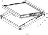
Fig. 1 window with lifting device -
Fig. 2 exploded view of lifting device -
Fig. 3 spatial view and top view of lifting device -
Fig. 4 front view of lifting device mounted on window side stile -
Fig. 5 back view of lifting device mounted on window side stile - In the first embodiment, the lifting device according to the invention is designed for a roof window. The roof window is constructed out of
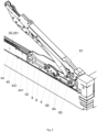
jamb 1 andsash 2 with a glass unit seated in a jamb via a hinge assembly, which facilitates at least a tilt opening of the roof window with the axis of rotation located byjamb 1 upper stile. On at least oneroof window jamb 1 side stile there is a lifting device according to the invention constructed out of spring assembly 3,adjustment assembly 4,coupling assembly 5 andsledge assembly 6, whereinsledge assembly 6 with liftingarm 61 comprise a connector between the lifting device andsash 2. After installing the window in a roof, the techniciancouples coupling assembly 5 withsledge assembly 6 and the roof window is ready for use. Spring assembly 3 is constructed out of twomain springs 31, with main inner springs inside them with a different spring constant and opposite coil directions as compared tomain springs 31.Main spring 31 and the main inner spring are seated onrods adjustment assembly 4front wall 41 and plasticadjustable plug 32, whose position onrod nut 33 androd rod adjustable plug 32. The location of eachadjustable plug 32 withnut 33 onrod main spring 31 and the main inner spring.Adjustment assembly 4 is constructed out of a chute with bottom 43,front wall 41 andback wall 42 with twolongitudinal walls 44. In theadjustment assembly 4 chute there is an auxiliary spring unit of the spring assembly, each constructed out twosprings appropriate rod Springs appropriate rod collet front wall 41 insideadjustment assembly 4 chute. Whereas the adjustment assembly chute includesadjustable plate 45, withopenings 451 fordevice rods arms 452 designed to be seated inadjustment assembly 4 chutelongitudinal walls 44edge grooves 441. There areopenings 431 inbottom 43 of the adjustment assembly chute foradjustable plate ridges 453, positioned to coincide withedge grooves 441 so thatedge grooves 441 andopenings 431 inbottom 43 of the chute share the same axis.Springs rods adjustable plate 45 andadjustment assembly 4chute front wall 41.Rods exit adjustment assembly 4 chute viaback wall openings 421 and connect tocoupling assembly 5.Coupling assembly 5 comprises a layered structure hook, one which is constructed out of two flatouter elements 51 with flatinner element 52 between them and connected to one another using screws 53. Flatouter elements 51 feature coaxial throughopenings 511, which establish a socket forrod spigot 82, which, in its installed state, is located belowsecond rod 9. The aforementionedsecond rod 9 also featuresspigot 92, which during coupling ofcoupling assembly 5 withsledge assembly 6 moves in hook flat outer elements' 51 openings, which are elongatedopenings 512 with the same curvature, so thatsecond rod 9spigot 92 moves in thoseelongated openings 512 simultaneously, duringcoupling assembly 5 rotation around the axis passing through devicefirst rod 8spigot 82. Flatinner element 52 includesridge 521 which limits hook rotation relative torod 8.Coupling assembly 5 includes a spring element in the form offlat spring 54 for self-positioning ofcoupling assembly 5 to its coupled position withsledge assembly 6.Flat spring 54 is seated incoupling assembly 5 flatinner element 52 socket, constitutingslot 55 for seatingflat spring 54 bent end. The second freeflat spring 54 end abutsfirst rod 8. The hook features a ramp plate surface which slides along coupling peg (65) during coupling of the coupling assembly with the sledge assembly until coupling peg (65) enters the hook socket.Coupling assembly 5 hook in the coupled position oncoupling peg 65 withsledge assembly 6slider 62 transfers movement ofrods arm 61 toroof window sash 2. Liftingarm 61 is rotatably attached tosledge assembly 6slider 62peg 63 and the axis of rotation passing through thatpeg 63 and slider 621 side walls, and the other end of liftingarm 61 is rotatably attached with intermediate arm z-section, such as disclosed in patent descriptionPL231796B1 Slider 62, moving insidechute 10 seated on jamb side stile.Slider 62 in the shape of a u-section, slides alongchute 10 bottom, and to reducefriction slider 62 features plastic slide overlays 64, located betweenslider 62 andchute bottom 10. These overlays overlapslider 62 side walls 621. - In the second embodiment, the solution features the properties of the first embodiment without
second rod 9 and without the elongated openings incoupling assembly 5 hookouter elements 51.
Claims (19)
- A roof window sash lifting device comprising- a spring assembly (3) with at least one main spring (31), and with at least one auxiliary spring unit seated in a device adjusting assembly (4),- a coupling assembly (5),- a sledge assembly (6),wherein the spring assembly (3) is seated on at least one rod (8, 9) which at one end terminates with an adjustable plug (32) abut with main spring (31) of the spring assembly (3), and the other end of the said rod (8, 9) is rotatably connected to the coupling assembly (5), and said coupling assembly (5) is designed for a detachable attachment to the device sledge assembly (6), characterised in thatthe coupling assembly (5) includes a spring element for self-positioning of the coupling assembly (5) to its coupled position with the sledge assembly (6).
- The roof window sash lifting device according to claim 1 characterized in that the spring element is a flat spring (54).
- The roof window sash lifting device according to claim 1 or 2 characterized in that the coupling assembly (5) is made out of plastic and includes a built-in flat spring (54).
- The roof window sash lifting device according to claim 1 or 2 characterized in that the coupling assembly (5) comprises a layered structure, so that the layers of the coupling assembly are connected to each other via flat elements.
- The roof window sash lifting device according to claim 4 characterized in that the coupling assembly includes two outer flat elements (51) with at least one flat inner element (52) between them.
- The roof window sash lifting device according to claim 4 or 5 characterized in that the flat outer elements (51) comprises a coaxial through openings (511), which establish a socket for rod (8) spigot (82) .
- The roof window sash lifting device according to claim 1 or 2, or 4, or 5, or 6 characterized in that the flat spring (54) is an element integrated with the inner element (52), so that it is positioned in the coupling assembly (5) flat inner element (52) socket, and is made out of plastic.
- The roof window sash lifting device according to claim 7 characterized in that the flat inner element socket is a slot (55) for seating the spring element.
- The roof window sash lifting device according to claim 1 or 2, or 3, or 4, or 5, or 6, or 7, or 8 characterized in that it comprises a second rod (9), on which second main spring (31) and second auxiliary spring unit are seated, wherein second rod (9) terminates with adjustable plug (32) which abuts second main spring (9) and is connected with coupling assembly (5) whose flat outer elements (51) feature elongated openings (512) with the same curvature, so that second rod (9) spigot (92) moves in those elongated openings (512) simultaneously, during coupling assembly (5) rotation around the axis passing through device first rod (8) spigot (82) .
- The roof window sash lifting device according to claim 1 or 2, or 3, or 4, or 5, or 6, or 7, or 8, or 9 characterized in that flat inner element (52) includes ridge (521) which limits coupling assembly (5) rotation angle relative to rod (8).
- The roof window sash lifting device according to claim 1 or 2, or 3, or 4, or 5, or 6, or 7, or 8, or 9, or 10 characterized in that adjustable plug (32) of first and second rods (8, 9) is attached to the appropriate rod by means of a threaded connection.
- The roof window sash lifting device according to claim 1 or 2, or 3, or 4, or 5, or 6, or 7, or 8, or 9, or 10, or 11 characterized in that coupling assembly (5) constitutes a hook.
- The roof window sash lifting device according to claim 12 characterized in that the hook features a ramp plate surface on which coupling peg (65) slides during coupling of the coupling assembly with the sledge assembly until coupling peg (65) enters the hook socket.
- The roof window sash lifting device according to claim 1 or 2, or 3, or 4, or 5, or 6, or 7, or 8, or 9, or 10, or 11, or 12, or 13 characterized in that adjustment assembly (4) is comprising a chute with an auxiliary spring unit inside it, wherein the chute front wall (41) constitutes an abutment for each main spring (8, 9) and on the opposite side that front wall (41) constitutes an abutment for the auxiliary spring unit, and in the chute there is adjustable plate (45) with openings (451) for rods, used to adjust the length of the adjustment assembly chute designed for an auxiliary spring unit.
- The roof window sash lifting device according to claim 14 characterized in that adjustment assembly (4) chute features at least one edge groove (441) in its longitudinal walls (44) determining at least one adjustable plate (45) position in the chute.
- The roof window sash lifting device according to claim 1 or 2, or 3, or 4, or 5, or 6, or 7, or 8, or 9, or 10, or 11, or 12, or 13, or 14, or 15 characterized in that the sledge assembly (6) comprises a chute with slider (62) and a lifting arm (61), so that the lifting arm (61) moves together with slider (62) coupled with the device coupling assembly.
- The roof window sash lifting device according to claim 1 or 2, or 3, or 4, or 5, or 6, or 7, or 8, or 9, or 10, or 11 or 12, or 13, or 14, or 15, or 16 characterized in that the auxiliary spring unit comperising two springs (35, 351) with a different spring constant and opposite coil directions positioned one inside the other.
- The roof window sash lifting device according to claim 17 characterized in that the auxiliary spring unit springs terminate with plugs (36).
- The roof window comprising a sash with glass unit, wherein sash (2) is seated in an articulated manner in a jamb (1) and the roof windows comprises the lifting device according to claims 1-16 so that sledge assembly (6), the spring assembly (3), the adjustment assembly (4) and the coupling assembly (5) are on jamb (1) stile and the sledge assembly (6) lifting arm (61) connects the lifting device according to claims 1-16 with roof window sash (2).
Applications Claiming Priority (1)
| Application Number | Priority Date | Filing Date | Title |
|---|---|---|---|
| PL443602A PL443602A1 (en) | 2023-01-27 | 2023-01-27 | Device for lifting the roof window sash and a roof window with this device |
Publications (3)
| Publication Number | Publication Date |
|---|---|
| EP4407133A1 true EP4407133A1 (en) | 2024-07-31 |
| EP4407133C0 EP4407133C0 (en) | 2025-11-26 |
| EP4407133B1 EP4407133B1 (en) | 2025-11-26 |
Family
ID=89474316
Family Applications (1)
| Application Number | Title | Priority Date | Filing Date |
|---|---|---|---|
| EP23220495.8A Active EP4407133B1 (en) | 2023-01-27 | 2023-12-28 | Roof window sash lifting device and a roof window with such a device |
Country Status (2)
| Country | Link |
|---|---|
| EP (1) | EP4407133B1 (en) |
| PL (1) | PL443602A1 (en) |
Cited By (1)
| Publication number | Priority date | Publication date | Assignee | Title |
|---|---|---|---|---|
| DK202470170A1 (en) * | 2024-06-18 | 2026-01-08 | Vkr Holding As | Roof window with a lifting device with a sledge guide having a rail forming part of a side frame reinforcement |
Citations (6)
| Publication number | Priority date | Publication date | Assignee | Title |
|---|---|---|---|---|
| US5070649A (en) * | 1988-04-08 | 1991-12-10 | V. Kann Rasmussen Industri A/S | Window, especially for installation in an inclined roof |
| US5689916A (en) * | 1993-12-10 | 1997-11-25 | V, Kann Rasmussen Industri A/S | Window particularly for installation in an inclined roof surface |
| US20160258199A1 (en) * | 2015-03-03 | 2016-09-08 | Hahn Gasfedern Gmbh | Spring and/or damping element |
| EP3348763A1 (en) * | 2017-01-16 | 2018-07-18 | FAKRO PP Sp. z o.o. | Intermediate arm assembly for a dual-function roof window |
| EP3714116B1 (en) | 2017-11-24 | 2021-09-08 | VKR Holding A/S | Roof window with improved spring assembly |
| EP3714125B1 (en) * | 2017-11-24 | 2021-09-08 | VKR Holding A/S | Roof window with a primary frame and at least one secondary frame, method for installing such a roof window and method for dismantling a secondary frame of the roof window |
Family Cites Families (3)
| Publication number | Priority date | Publication date | Assignee | Title |
|---|---|---|---|---|
| PL210344B1 (en) * | 2004-04-30 | 2012-01-31 | Fakro Pp Społka Z Ograniczoną Odpowiedzialnością | Skylight with two functions: pivoting and opening |
| PL206424B1 (en) * | 2007-06-11 | 2010-08-31 | Kaczy & Nacute Ska Renata Dobr | Device for determination of roof window wing location |
| PL242906B1 (en) * | 2019-11-22 | 2023-05-15 | Fakro Pp Spolka Z Ograniczona Odpowiedzialnoscia | Double-sash roof window |
-
2023
- 2023-01-27 PL PL443602A patent/PL443602A1/en unknown
- 2023-12-28 EP EP23220495.8A patent/EP4407133B1/en active Active
Patent Citations (7)
| Publication number | Priority date | Publication date | Assignee | Title |
|---|---|---|---|---|
| US5070649A (en) * | 1988-04-08 | 1991-12-10 | V. Kann Rasmussen Industri A/S | Window, especially for installation in an inclined roof |
| US5689916A (en) * | 1993-12-10 | 1997-11-25 | V, Kann Rasmussen Industri A/S | Window particularly for installation in an inclined roof surface |
| US20160258199A1 (en) * | 2015-03-03 | 2016-09-08 | Hahn Gasfedern Gmbh | Spring and/or damping element |
| EP3348763A1 (en) * | 2017-01-16 | 2018-07-18 | FAKRO PP Sp. z o.o. | Intermediate arm assembly for a dual-function roof window |
| PL231796B1 (en) | 2017-01-16 | 2019-04-30 | Fakro Pp Spolka Z Ograniczona Odpowiedzialnoscia | Intermediate arm assembly in a bifunctional roof window |
| EP3714116B1 (en) | 2017-11-24 | 2021-09-08 | VKR Holding A/S | Roof window with improved spring assembly |
| EP3714125B1 (en) * | 2017-11-24 | 2021-09-08 | VKR Holding A/S | Roof window with a primary frame and at least one secondary frame, method for installing such a roof window and method for dismantling a secondary frame of the roof window |
Cited By (2)
| Publication number | Priority date | Publication date | Assignee | Title |
|---|---|---|---|---|
| DK202470170A1 (en) * | 2024-06-18 | 2026-01-08 | Vkr Holding As | Roof window with a lifting device with a sledge guide having a rail forming part of a side frame reinforcement |
| DK182420B1 (en) * | 2024-06-18 | 2026-08-06 | Vkr Holding As | Roof window with a lifting device with a sledge guide having a rail forming part of a side frame reinforcement |
Also Published As
| Publication number | Publication date |
|---|---|
| PL443602A1 (en) | 2024-07-29 |
| EP4407133C0 (en) | 2025-11-26 |
| EP4407133B1 (en) | 2025-11-26 |
Similar Documents
| Publication | Publication Date | Title |
|---|---|---|
| US5052079A (en) | Pivoted fitting or turn-and-tilt fitting for windows, doors | |
| EP4407133B1 (en) | Roof window sash lifting device and a roof window with such a device | |
| US10253540B2 (en) | Apparatus for connecting door closer or operator to swing door | |
| CA2046988C (en) | Torque rod counterbalanced door assembly | |
| CA2331459C (en) | Buffer device | |
| DE19945081C2 (en) | Ceiling-supported suspension for a device, in particular an operating light | |
| EP2770146A1 (en) | An improved pivot hinge fitting and a roof window comprising such a hinge fitting | |
| PL176763B1 (en) | Window in particular for mounting in inclined roof surface | |
| EP3505712A1 (en) | Roof window | |
| CN111779393B (en) | Door systems | |
| EP0360995A1 (en) | Hardware set for coplanar sliding closet doors | |
| DE69417469T2 (en) | Chain drive for windows | |
| EP0819804A2 (en) | Articulated arm for an awning with articulated arms | |
| EP2085548A1 (en) | A hinge for doors or windows | |
| EP4567239A1 (en) | A roof window with a lifting device | |
| US20250116115A1 (en) | Lifting mechanism for scissor attic stairs, attic stairs, and method of lifting attic stairs using a lifting mechanism | |
| US20050179279A1 (en) | System for counterbalancing a tailgate | |
| DE102019211796B4 (en) | Guide fitting for a sliding leaf assembly and sliding leaf assembly | |
| HUE028281T2 (en) | A lifting device for a roof window | |
| DK201770887A1 (en) | Roof window with improved spring assembly | |
| DE202010008353U1 (en) | awning | |
| EP1908892A2 (en) | Skylight | |
| EP0674062B1 (en) | Awning mechanism | |
| CN121941826A (en) | Fitting for sliding/tilting window | |
| EP2105565B1 (en) | Drive to operate the leaf of a window |
Legal Events
| Date | Code | Title | Description |
|---|---|---|---|
| PUAI | Public reference made under article 153(3) epc to a published international application that has entered the european phase |
Free format text: ORIGINAL CODE: 0009012 |
|
| STAA | Information on the status of an ep patent application or granted ep patent |
Free format text: STATUS: THE APPLICATION HAS BEEN PUBLISHED |
|
| AK | Designated contracting states |
Kind code of ref document: A1 Designated state(s): AL AT BE BG CH CY CZ DE DK EE ES FI FR GB GR HR HU IE IS IT LI LT LU LV MC ME MK MT NL NO PL PT RO RS SE SI SK SM TR |
|
| STAA | Information on the status of an ep patent application or granted ep patent |
Free format text: STATUS: REQUEST FOR EXAMINATION WAS MADE |
|
| 17P | Request for examination filed |
Effective date: 20250311 |
|
| GRAP | Despatch of communication of intention to grant a patent |
Free format text: ORIGINAL CODE: EPIDOSNIGR1 |
|
| STAA | Information on the status of an ep patent application or granted ep patent |
Free format text: STATUS: GRANT OF PATENT IS INTENDED |
|
| GRAS | Grant fee paid |
Free format text: ORIGINAL CODE: EPIDOSNIGR3 |
|
| INTG | Intention to grant announced |
Effective date: 20250826 |
|
| GRAA | (expected) grant |
Free format text: ORIGINAL CODE: 0009210 |
|
| STAA | Information on the status of an ep patent application or granted ep patent |
Free format text: STATUS: THE PATENT HAS BEEN GRANTED |
|
| AK | Designated contracting states |
Kind code of ref document: B1 Designated state(s): AL AT BE BG CH CY CZ DE DK EE ES FI FR GB GR HR HU IE IS IT LI LT LU LV MC ME MK MT NL NO PL PT RO RS SE SI SK SM TR |
|
| REG | Reference to a national code |
Ref country code: CH Ref legal event code: F10 Free format text: ST27 STATUS EVENT CODE: U-0-0-F10-F00 (AS PROVIDED BY THE NATIONAL OFFICE) Effective date: 20251126 Ref country code: GB Ref legal event code: FG4D |
|
| REG | Reference to a national code |
Ref country code: IE Ref legal event code: FG4D |
|
| U01 | Request for unitary effect filed |
Effective date: 20251126 |
|
| U07 | Unitary effect registered |
Designated state(s): AT BE BG DE DK EE FI FR IT LT LU LV MT NL PT RO SE SI Effective date: 20251201 |
|
| PGFP | Annual fee paid to national office [announced via postgrant information from national office to epo] |
Ref country code: AT Payment date: 20260113 Year of fee payment: 3 |
|
| U20 | Renewal fee for the european patent with unitary effect paid |
Year of fee payment: 3 Effective date: 20251205 |
|
| PG25 | Lapsed in a contracting state [announced via postgrant information from national office to epo] |
Ref country code: ES Free format text: LAPSE BECAUSE OF FAILURE TO SUBMIT A TRANSLATION OF THE DESCRIPTION OR TO PAY THE FEE WITHIN THE PRESCRIBED TIME-LIMIT Effective date: 20251126 |
|
| PG25 | Lapsed in a contracting state [announced via postgrant information from national office to epo] |
Ref country code: NO Free format text: LAPSE BECAUSE OF FAILURE TO SUBMIT A TRANSLATION OF THE DESCRIPTION OR TO PAY THE FEE WITHIN THE PRESCRIBED TIME-LIMIT Effective date: 20260226 |
|
| PG25 | Lapsed in a contracting state [announced via postgrant information from national office to epo] |
Ref country code: HR Free format text: LAPSE BECAUSE OF FAILURE TO SUBMIT A TRANSLATION OF THE DESCRIPTION OR TO PAY THE FEE WITHIN THE PRESCRIBED TIME-LIMIT Effective date: 20251126 |
|
| PG25 | Lapsed in a contracting state [announced via postgrant information from national office to epo] |
Ref country code: RS Free format text: LAPSE BECAUSE OF FAILURE TO SUBMIT A TRANSLATION OF THE DESCRIPTION OR TO PAY THE FEE WITHIN THE PRESCRIBED TIME-LIMIT Effective date: 20260226 |
|
| PG25 | Lapsed in a contracting state [announced via postgrant information from national office to epo] |
Ref country code: IS Free format text: LAPSE BECAUSE OF FAILURE TO SUBMIT A TRANSLATION OF THE DESCRIPTION OR TO PAY THE FEE WITHIN THE PRESCRIBED TIME-LIMIT Effective date: 20260326 |
|
| PG25 | Lapsed in a contracting state [announced via postgrant information from national office to epo] |
Ref country code: PL Free format text: LAPSE BECAUSE OF FAILURE TO SUBMIT A TRANSLATION OF THE DESCRIPTION OR TO PAY THE FEE WITHIN THE PRESCRIBED TIME-LIMIT Effective date: 20251126 |
|
| PG25 | Lapsed in a contracting state [announced via postgrant information from national office to epo] |
Ref country code: SM Free format text: LAPSE BECAUSE OF FAILURE TO SUBMIT A TRANSLATION OF THE DESCRIPTION OR TO PAY THE FEE WITHIN THE PRESCRIBED TIME-LIMIT Effective date: 20251126 |
|
| PG25 | Lapsed in a contracting state [announced via postgrant information from national office to epo] |
Ref country code: CZ Free format text: LAPSE BECAUSE OF FAILURE TO SUBMIT A TRANSLATION OF THE DESCRIPTION OR TO PAY THE FEE WITHIN THE PRESCRIBED TIME-LIMIT Effective date: 20251126 |
|
| PG25 | Lapsed in a contracting state [announced via postgrant information from national office to epo] |
Ref country code: SK Free format text: LAPSE BECAUSE OF FAILURE TO SUBMIT A TRANSLATION OF THE DESCRIPTION OR TO PAY THE FEE WITHIN THE PRESCRIBED TIME-LIMIT Effective date: 20251126 |
|
| PG25 | Lapsed in a contracting state [announced via postgrant information from national office to epo] |
Ref country code: MC Free format text: LAPSE BECAUSE OF FAILURE TO SUBMIT A TRANSLATION OF THE DESCRIPTION OR TO PAY THE FEE WITHIN THE PRESCRIBED TIME-LIMIT Effective date: 20251126 |