EP4407099A1 - Mobile barrier for allowing/blocking the flow of traffic along a transit path - Google Patents
Mobile barrier for allowing/blocking the flow of traffic along a transit path Download PDFInfo
- Publication number
- EP4407099A1 EP4407099A1 EP23305088.9A EP23305088A EP4407099A1 EP 4407099 A1 EP4407099 A1 EP 4407099A1 EP 23305088 A EP23305088 A EP 23305088A EP 4407099 A1 EP4407099 A1 EP 4407099A1
- Authority
- EP
- European Patent Office
- Prior art keywords
- barrier
- end portion
- mounting end
- boom
- mobile
- Prior art date
- Legal status (The legal status is an assumption and is not a legal conclusion. Google has not performed a legal analysis and makes no representation as to the accuracy of the status listed.)
- Granted
Links
Images


Classifications
-
- E—FIXED CONSTRUCTIONS
- E01—CONSTRUCTION OF ROADS, RAILWAYS, OR BRIDGES
- E01F—ADDITIONAL WORK, SUCH AS EQUIPPING ROADS OR THE CONSTRUCTION OF PLATFORMS, HELICOPTER LANDING STAGES, SIGNS, SNOW FENCES, OR THE LIKE
- E01F13/00—Arrangements for obstructing or restricting traffic, e.g. gates, barricades ; Preventing passage of vehicles of selected category or dimensions
- E01F13/04—Arrangements for obstructing or restricting traffic, e.g. gates, barricades ; Preventing passage of vehicles of selected category or dimensions movable to allow or prevent passage
- E01F13/06—Arrangements for obstructing or restricting traffic, e.g. gates, barricades ; Preventing passage of vehicles of selected category or dimensions movable to allow or prevent passage by swinging into open position about a vertical or horizontal axis parallel to the road direction, i.e. swinging gates
-
- B—PERFORMING OPERATIONS; TRANSPORTING
- B61—RAILWAYS
- B61L—GUIDING RAILWAY TRAFFIC; ENSURING THE SAFETY OF RAILWAY TRAFFIC
- B61L29/00—Safety means for rail/road crossing traffic
- B61L29/04—Gates for level crossings
-
- B—PERFORMING OPERATIONS; TRANSPORTING
- B61—RAILWAYS
- B61L—GUIDING RAILWAY TRAFFIC; ENSURING THE SAFETY OF RAILWAY TRAFFIC
- B61L29/00—Safety means for rail/road crossing traffic
- B61L29/08—Operation of gates; Combined operation of gates and signals
- B61L29/10—Means for securing gates in their desired position
Definitions
- the present invention concerns a mobile barrier for allowing/blocking the flow of traffic along a transit path.
- the mobile barrier according to the invention is especially suitable for being applied at railway level crossings, and will be described hereinafter by making particular reference to such application, without intending in any way to limit its possible use in other types of transit paths.
- the movable barrier according to the present invention can be used in toll stations of highways or of any road where transit is not free, at the entrance/exit of guarded areas, parking lots, areas with restricted access, et cetera.
- a typical example is represented by railway level crossings where the barriers at both sides of a railway are normally raised and then temporarily lowered in order to block the transit over the rails of vehicles, pedestrians, bicycles, et cetera, until a train has passed by.
- each mobile barrier is mounted on and actuated by a driving unit which is housed inside a casing or small column placed at a side of the traffic path.
- the devised structure has to be modified depending on whether a movable barrier has to be installed on the right side or on the left side of the passage path.
- the completely free breakage and release of the main part relative to the end part coupled to the drive unit can cause potentially dangerous situations, for instance since the broken part may end over the rails.
- a mobile barrier for allowing/blocking the flow of traffic along a transit path comprising at least:
- the mobile barrier according to the invention may comprise one or more of the following features, which may be combined in any technical feasible combination:
- any component as a whole, or to any part of a component, or to a combination of components, it has to be understood that it means and encompasses correspondingly either the structure, and/or configuration and/or form and/or positioning of the related component or part thereof, or combinations, such term refers to.
- transversal or transversally are hereby used, they have to be understood as encompassing a direction non-parallel to the reference part(s) or direction(s)/axis they refer to, and perpendicularity has to be considered a specific case of transverse direction.
- Figure 1 illustrates a possible embodiment of a mobile barrier 1 according to the invention for allowing/blocking the flow of traffic along a transit path indicated in figure 5 by the arrow P for both directions.
- the mobile barrier 1 comprises a mounting end portion 4 which is configured to be coupled to a drive unit suitable for rotating the mobile barrier 1 around a first axis, indicated in figures 3 to 5 with the capital letter X, between a raised position, where the flow of traffic along the transit path P is allowed, and a lowered position where the flow of traffic is at least temporarily blocked.
- Such drive unit can be accommodated in a housing 100 installed at the side of the path P, e.g. a side of a road crossed by a railway 10, and is arranged for rotating the mobile barrier 1 around the first axis X; to this end, the mounting end portion 4 is mounted on a rotating shaft of the drive unit.
- the configuration of the drive unit, its installation inside the housing 100, as well as the coupling of the mounting end portion 4 with the drive unit and in particular to the rotating shaft, can be realized according to solutions well known in the art or in any case readily available to those skilled in the art, and therefore not described herein in detail.
- the mobile barrier 1 according to the invention further comprises also at least:
- the barrier boom 3 forms the part of the mobile barrier 1 which is suitable to be positioned across the transit path P when the mobile barrier 1 is in the lowered position, thus at least temporarily hindering the flow of traffic along the transit path P.
- the barrier boom 3 comprises a tubular body made of a lightweight material, such as aluminum.
- the barrier boom 3 has a modular structure, i.e. its body is formed by a plurality of sections or modules, e.g. two or more, assembled to each other.
- the length of the whole barrier boom 3 can be easily sized according to the installation site of the mobile barrier 1.
- the barrier boom 3 comprises two tubular pieces, namely a first piece 5 positioned at the free end of the barrier boom 3, and a second longer piece which extends from the end piece 5 towards the mounting end portion 4.
- connection between the pieces of the barrier boom 3, such as between the tubular end piece 5 and the other part of the boom 3, can be realized easily, e.g. via a telescopic coupling by inserting a portion of one piece into the adjacent one.
- the barrier boom 3 comprises one or more signaling lights, such as LEDs, which are distributed, spaced apart from each other, along the longitudinal extension of its body; for instance, in figure 1 there are schematically illustrated three signaling lights indicated by the reference number 2.
- Each position along the barrier boom 3 devised for positioning a signaling light 2 is provided with a suitable cable holder.
- connection means are configured to connect the barrier boom 3 to the mounting end portion 4 so that they rotate substantially solidly with each other around the first axis X between the raised position and the lowered position, and also to allow the barrier boom 3 to rotate relative to the mounting end portion 4 around a third axis transversal to the first and second axes X and Y (indicated in figure 4 by the capital letter Z), when the barrier boom 3 is hit by a body which exerts on the barrier boom 3 a force indicated in figure 5 by the arrow F, is higher than a predefined threshold.
- this predefined threshold can be adjustable.
- Such body can be for example a vehicle, a bicycle, et cetera, and, depending on the angle of inclination of the impacting body, the force to be considered as higher than a predefined threshold can be the whole force F, i. e. the body impacts the barrier boom 3 substantially perpendicularly to the vertical virtual plane where the barrier boom 3 moves between the raised and lower positions, or preferably its component directed substantially perpendicularly to such vertical virtual plane, i.e. the force component directed along the transit path P (namely substantially along the first axis X).
- connection means are configured to connect the barrier boom 3 to the mounting end portion 4 allowing the barrier boom 3 to rotate relative to the mounting portion 4 around the third axis Z either clockwise and counterclockwise when hit by the impacting body.
- the mobile barrier 1 can have the same structure regardless of whether it has to be installed on one or the other side of the associated transit path P, namely on right or left road sides and on exits/entrances from/to level crossing areas.
- connection means are configured to keep the barrier boom 3 mechanically connected to the mounting portion 4 when the barrier boom 3 is hit by a body and rotates relative to the mounting end portion 4, at least until the level of force exerted by the hitting body does not exceed the predefined threshold.
- the barrier boom 3 is connected to the mounting portion 4 by means of a hinge mechanism which does not allow the barrier boom 3 to drop off, thus differently from known solutions where existing barriers are mechanically disconnected from the mounting points when impacted and among other cut the power wires to lights.
- the present solution does not cut wires and allows quickly reassembling barrier booms to guarding positions after accident, requiring the presence of a single person, while known solution need at least two people.
- connection means comprise means for limiting the rotation around the third axis Z of the barrier boom 3 relative to the mounting portion 4 up to a predefined angular threshold.
- connection means comprise a connector 20 having one end portion 21 which is fitted inside and is mechanically secured to one end of the barrier boom 3, and an opposite end portion 9 which is inserted inside a cavity 50 provided in the mounting end portion 4.
- the end portion 21 can be releasably secured to the end portion of the barrier boom 3 via a plurality of fixing screws 15.
- connection means further comprise a rotation pivot 6 which is positioned inside the mounting end portion 4; in particular, the rotating pivot 6 has a body, e.g. substantially cylindrical, which is inserted in a through opening 22 of and extends transversally with respect to the connector 20.
- the rotation pivot 6, and in particular its axis, defines the third axis Z once the mobile barrier 1 is installed.
- connection means further comprise:
- the closing cap 12 forms a sort of cap washer fixed inside the cavity 24 of the connector 20, and substantially contributes to hold the spherical body 8 in position inside the cavity of the connector 20 in normal operating conditions.
- the closing cap 12 works together with a breaking washer 9 that is fixedly connected to the mounting part 4 and protrudes inside the cavity 24 and has a surface which is geometrically conjugated with and adapted to keep the spherical body 8 urging against the preloaded spring 7 in normal operating conditions, i.e. when the barrier boom 3 is not hit by any object.
- the spherical body 8 urges against the preloaded spring 7, thus the barrier boom 3 is blocked in position and rotates solidly with the various connection means and the mounting end portion 4 between the raised and lowered positions.
- the spherical body 8 moves towards and inside the cavity 24; thus, the barrier boom is unlocked and, under the action of the impacting force, can rotate about the pivot 6, and in particular around the axis Z, together with the connector 20 relative to the mounting end portion 4.
- connection means devised allow the barrier boom 3 to rotate clockwise or counterclockwise depending on the direction of the impacting body.
- the mobile barrier 1 further comprises an alarm device, indicated in figures 2 and 4 by the reference number 10, which is operatively associated with the connection means and is configured to automatically output an alarm signal indicative that the barrier boom 3 has rotated around the third axis Z relative to the mounting end portion 4 due to being hit by a body.
- an alarm device indicated in figures 2 and 4 by the reference number 10 which is operatively associated with the connection means and is configured to automatically output an alarm signal indicative that the barrier boom 3 has rotated around the third axis Z relative to the mounting end portion 4 due to being hit by a body.
- the alarm device 10 is fully embedded inside the structure of the mobile barrier 1, and in particular inside the body of the mounting end portion 4.
- an electrical junction box 13 is conveniently located inside the mounting part 4.
- the alarm device 10 comprises a normally closed switch which has one contact portion, for instance a roller, arranged to rest against the substantially spherical body 8 in normal operating conditions, and to be spaced therefrom when the spherical body 8 displaces away inside the cavity 24 as above indicated.
- one contact portion for instance a roller
- the electrical circuit is interrupted and the switch 10 automatically outputs a signal indicative that the barrier boom 3 has been hit by a body and has rotated relative to the mounting end portion 4.
- This signal is suitable for warning operators and can be used locally, for instance to lit a warning light, e.g. on the housing 100, or it can be sent remotely from the mobile barrier 1, e.g. in a control room.
- an internal channel is defined inside at least the mounting end portion 4 and the connection means, in particular the rotating pivot 6 and the connector 20; usefully this internal channel 30 is configured to route towards the one or more signaling lights 2 of the barrier boom 3, one or more power cables, schematically indicated in figure 2 by the reference number 31.
- an opening 32 is provided onto the mounting end portion 4 to grant access to access points of such power cables if necessary during all operating states, i.e. when the barrier 1 is raised, lowered, and after being hit and reassembled.
- the movable barrier 1 allows achieving the intended aim since it has an optimized structure which can be installed on the right or left side without any substantial modification, where the barrier boom 3 can rotate in both directions.
- the barrier boom is properly configured to limit the possibility that the barrier boom 3 is always detached from the mounting end portion 4, at least up to a certain level of impacting force, which is particularly important for some applications, such in railway level crossings.
- the mobile barrier 1 thus conceived is susceptible of modifications and variations, all of which are within the scope of the inventive concept as defined in particular by the appended claims; for example, in relation to the specific application, some of the components described can be differently shaped or sized, the material used for each of them can be any suitable one, et cetera.
Landscapes
- Engineering & Computer Science (AREA)
- Mechanical Engineering (AREA)
- Architecture (AREA)
- Civil Engineering (AREA)
- Structural Engineering (AREA)
- Refuge Islands, Traffic Blockers, Or Guard Fence (AREA)
- Train Traffic Observation, Control, And Security (AREA)
Abstract
- a mounting end portion (4) configured to be coupled to a drive unit suitable for rotating the mobile barrier (1) around a first axis (X) between a raised position where the flow of traffic along the transit path (P) is allowed and a lowered position where the flow of traffic is at least temporarily blocked;
- a barrier boom (3) which extends longitudinally along a second axis (Y) transversal to the first axis (X); and
- connection means (20, 6, 7, 8) which interconnect mechanically the mounting end portion (4) to one end of the barrier boom (3).
Description
- The present invention concerns a mobile barrier for allowing/blocking the flow of traffic along a transit path.
- The mobile barrier according to the invention is especially suitable for being applied at railway level crossings, and will be described hereinafter by making particular reference to such application, without intending in any way to limit its possible use in other types of transit paths.
- For example, the movable barrier according to the present invention can be used in toll stations of highways or of any road where transit is not free, at the entrance/exit of guarded areas, parking lots, areas with restricted access, et cetera.
- The use of mobile barriers for allowing or blocking at least temporarily the flow of traffic along a transit path is well known in the art.
- A typical example is represented by railway level crossings where the barriers at both sides of a railway are normally raised and then temporarily lowered in order to block the transit over the rails of vehicles, pedestrians, bicycles, et cetera, until a train has passed by.
- Typically, at the installation sites, each mobile barrier is mounted on and actuated by a driving unit which is housed inside a casing or small column placed at a side of the traffic path.
- Since in operations mobile barriers may be subject to impacts, namely when lowered they can be accidentally hit for example by approaching vehicles, bicycles, et cetera, some solutions have been adopted to allow the main part of the barrier extending along the passage path to break relative to and be released from the end part connected to the drive unit; further, according to this solution, some known mobile barriers have been provided also with means, typically sheer wires, for checking the structural continuity of the mobile barriers themselves.
- In this way, in case of impacts, the possibility of damaging also the drive unit is mitigated and operators can also visually check, following an impact, the current continuity of the barriers.
- Although the structures of known mobile barriers have been ameliorated over the years and perform their functionalities in a quite satisfying way, there is still room and desire for further improvements under various aspects.
- For example, in some known solutions the devised structure has to be modified depending on whether a movable barrier has to be installed on the right side or on the left side of the passage path.
- In some applications, like at railway level crossings, the completely free breakage and release of the main part relative to the end part coupled to the drive unit can cause potentially dangerous situations, for instance since the broken part may end over the rails.
- Further, the use of sheer wires is somehow cumbersome for the realization of mobile barriers and implies that continuity checks can be performed only via visual inspection of the barriers.
- Therefore, it is a main aim of the present invention to fulfill at least partially such room and desire, and in particular to provide a movable barrier capable of at least mitigating one or more of the above mentioned issues.
- This aim is achieved by a mobile barrier for allowing/blocking the flow of traffic along a transit path, comprising at least:
- a mounting end portion which is configured to be coupled to a drive unit suitable for rotating the mobile barrier around a first axis between a raised position where the flow of traffic along the transit path is allowed and a lowered position where the flow of traffic is at least temporarily blocked;
- a barrier boom having a body which extends longitudinally along a second axis transversal to said first axis; and
- connection means which interconnect mechanically the mounting end portion to one end of the barrier boom;
- According to some embodiments, the mobile barrier according to the invention may comprise one or more of the following features, which may be combined in any technical feasible combination:
- the connection means are configured to connect the barrier boom to the mounting end portion to allow the barrier boom rotating relative to the mounting end portion around said third axis either clockwise and counterclockwise when hit by said body;
- the connection means are configured to keep said barrier boom mechanically connected to the mounting portion when the barrier boom is hit by said body and rotates relative to the mounting end portion;
- the connection means comprise means for limiting the rotation around the third axis of the barrier boom relative to the mounting end portion until a predefined angular threshold is reached;
- the connection means comprise a connector having one end portion which is fitted inside and is mechanically secured to said one end of the barrier boom, and an opposite end portion which is inserted inside a cavity provided in the mounting end portion;
- the connection means further comprise a pivot, positioned inside said mounting end portion, said pivot having a body which is inserted in a through opening of and extends transversally with respect to the connector;
- the connection means further comprise:
- at least one preloaded spring which is fitted at least partially inside a further cavity provided at said opposite end portion of the connector;
- a substantially spherical body which is housed at least partially inside a cavity and resides on a seat provided in the connector and is suitable to urge against and contrast the movement of the preloaded spring; and
- a closing cap which protrudes inside said cavity and compresses the at least one preloaded spring to hold the spherical body in position inside the cavity in normal operating conditions.
- the mobile barrier further comprises an alarm device which is operatively associated with said connection means and is configured to automatically output a signal indicative that the barrier boom has rotated around said third axis relative to the mounting end portion due to being hit by said body;
- the alarm device is embedded inside said mounting end portion;
- the alarm device comprises a normally closed switch which has one contact portion arranged to rest against the substantially spherical body in normal operating conditions, and to be spaced therefrom when the spherical body is displaced away following the rotation of the barrier boom relative to the mounting end portion due to being hit by said body, and wherein, when the contact portion is spaced from the spherical body, said normally closed switch automatically outputs a signal indicative that the barrier boom has been hit by said body and has rotated relative to the mounting end portion;
- the barrier boom comprises one or more signaling lights, and wherein an internal channel is defined inside at least the mounting end portion and at least part of the connection means and is configured to route towards the one or more signaling lights of the barrier boom one or more power cables;
- the barrier boom has a tubular body made of a lightweight material;
- the barrier boom comprises a modular body formed by a plurality of sections assembled to each other;
- the sections of said plurality of sections are mutually assembled by means of telescopic couplings;
- the mobile barrier further comprising an electrical junction box located inside the mounting part.
- Further characteristics and advantages will become apparent from the description of some preferred but not exclusive exemplary embodiments of a mobile barrier according to the present invention, illustrated only by way of non-limitative examples with the accompanying drawings, wherein:
-
Figure 1 is a view front view schematically showing an embodiment of a mobile barrier according to the invention; -
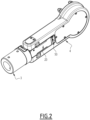
Figure 2 is a perspective view illustrating some parts of the mobile barrier offigure 1 ; -
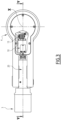
Figure 3 is a side view, with a partial cross section, of the parts of the mobile barrier illustrated infigure 2 ; -
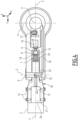
Figure 4 is a cross section of part of the mobile barrier offigure 1 , according to one possible embodiment; -
Figure 5 shows a mobile barrier according to the invention installed at a railway level crossing. - It should be noted that in the detailed description that follows, identical or similar components, either from a structural and/or functional point of view, may have the same or different reference numerals, regardless of whether they are shown in different embodiments of the present disclosure; it should also be noted that in order to clearly and concisely describe the present disclosure, the drawings may not necessarily be to scale and certain features of the disclosure may be shown in somewhat schematic form.
- Further, when the term "adapted" or "arranged" or "configured" or "shaped", or any similar term is used herein while referring to any component as a whole, or to any part of a component, or to a combination of components, it has to be understood that it means and encompasses correspondingly either the structure, and/or configuration and/or form and/or positioning of the related component or part thereof, or combinations, such term refers to.
- In addition, when the term "about" or "substantial" or "substantially" is used herein, it has to be understood as encompassing an actual variation of plus or
minus 5% with respect to an indicated reference axis or position, and when these terms are used with reference to moving parts, e.g. two parts moving substantially solidly to each other, it has to be understood that they move together apart from unavoidable mechanical inertia, - Finally, when the terms transversal or transversally are hereby used, they have to be understood as encompassing a direction non-parallel to the reference part(s) or direction(s)/axis they refer to, and perpendicularity has to be considered a specific case of transverse direction.
-
Figure 1 illustrates a possible embodiment of amobile barrier 1 according to the invention for allowing/blocking the flow of traffic along a transit path indicated infigure 5 by the arrow P for both directions. - In particular, the
mobile barrier 1 comprises amounting end portion 4 which is configured to be coupled to a drive unit suitable for rotating themobile barrier 1 around a first axis, indicated infigures 3 to 5 with the capital letter X, between a raised position, where the flow of traffic along the transit path P is allowed, and a lowered position where the flow of traffic is at least temporarily blocked. - Such drive unit can be accommodated in a
housing 100 installed at the side of the path P, e.g. a side of a road crossed by arailway 10, and is arranged for rotating themobile barrier 1 around the first axis X; to this end, themounting end portion 4 is mounted on a rotating shaft of the drive unit. - The configuration of the drive unit, its installation inside the
housing 100, as well as the coupling of themounting end portion 4 with the drive unit and in particular to the rotating shaft, can be realized according to solutions well known in the art or in any case readily available to those skilled in the art, and therefore not described herein in detail. - The
mobile barrier 1 according to the invention further comprises also at least: - a
barrier boom 3 which extends, from themounting end portion 4, longitudinally along a second axis which is transversal to the first axis X, and is indicated infigures 3 and4 by the capital letter Y; and - connection means which interconnect mechanically the
mounting end portion 4 to one end of thebarrier boom 3. - In operations, the
barrier boom 3 forms the part of themobile barrier 1 which is suitable to be positioned across the transit path P when themobile barrier 1 is in the lowered position, thus at least temporarily hindering the flow of traffic along the transit path P. - In particular, in one possible embodiment of the
mobile barrier 1 according to the invention, thebarrier boom 3 comprises a tubular body made of a lightweight material, such as aluminum. - Usefully, in one possible embodiment, the
barrier boom 3 has a modular structure, i.e. its body is formed by a plurality of sections or modules, e.g. two or more, assembled to each other. - In this way, the length of the
whole barrier boom 3 can be easily sized according to the installation site of themobile barrier 1. - For instance, in the exemplary embodiment of the
mobile barrier 1 illustrated infigure 1 , thebarrier boom 3 comprises two tubular pieces, namely afirst piece 5 positioned at the free end of thebarrier boom 3, and a second longer piece which extends from theend piece 5 towards themounting end portion 4. - The connection between the pieces of the
barrier boom 3, such as between thetubular end piece 5 and the other part of theboom 3, can be realized easily, e.g. via a telescopic coupling by inserting a portion of one piece into the adjacent one. - In yet a possible embodiment, the
barrier boom 3 comprises one or more signaling lights, such as LEDs, which are distributed, spaced apart from each other, along the longitudinal extension of its body; for instance, infigure 1 there are schematically illustrated three signaling lights indicated by thereference number 2. - Each position along the
barrier boom 3 devised for positioning a signalinglight 2 is provided with a suitable cable holder. - Conveniently, in the
mobile barrier 1 according to the invention, the connection means are configured to connect thebarrier boom 3 to themounting end portion 4 so that they rotate substantially solidly with each other around the first axis X between the raised position and the lowered position, and also to allow thebarrier boom 3 to rotate relative to themounting end portion 4 around a third axis transversal to the first and second axes X and Y (indicated infigure 4 by the capital letter Z), when thebarrier boom 3 is hit by a body which exerts on the barrier boom 3 a force indicated infigure 5 by the arrow F, is higher than a predefined threshold. - Advantageously, this predefined threshold can be adjustable.
- Such body can be for example a vehicle, a bicycle, et cetera, and, depending on the angle of inclination of the impacting body, the force to be considered as higher than a predefined threshold can be the whole force F, i. e. the body impacts the
barrier boom 3 substantially perpendicularly to the vertical virtual plane where thebarrier boom 3 moves between the raised and lower positions, or preferably its component directed substantially perpendicularly to such vertical virtual plane, i.e. the force component directed along the transit path P (namely substantially along the first axis X). - In particular, in one possible embodiment, the connection means are configured to connect the
barrier boom 3 to themounting end portion 4 allowing thebarrier boom 3 to rotate relative to themounting portion 4 around the third axis Z either clockwise and counterclockwise when hit by the impacting body. - In this way, the
mobile barrier 1 can have the same structure regardless of whether it has to be installed on one or the other side of the associated transit path P, namely on right or left road sides and on exits/entrances from/to level crossing areas. - In yet a further embodiment, the connection means are configured to keep the
barrier boom 3 mechanically connected to the mountingportion 4 when thebarrier boom 3 is hit by a body and rotates relative to the mountingend portion 4, at least until the level of force exerted by the hitting body does not exceed the predefined threshold. - In practice, and as it will result more in details hereinafter, the
barrier boom 3 is connected to the mountingportion 4 by means of a hinge mechanism which does not allow thebarrier boom 3 to drop off, thus differently from known solutions where existing barriers are mechanically disconnected from the mounting points when impacted and among other cut the power wires to lights. - The present solution does not cut wires and allows quickly reassembling barrier booms to guarding positions after accident, requiring the presence of a single person, while known solution need at least two people.
- In particular, the connection means comprise means for limiting the rotation around the third axis Z of the
barrier boom 3 relative to the mountingportion 4 up to a predefined angular threshold. - In particular, as illustrated in
figures 2 to 4 , in one possible embodiment of themobile barrier 1 according to the invention, the connection means comprise aconnector 20 having oneend portion 21 which is fitted inside and is mechanically secured to one end of thebarrier boom 3, and anopposite end portion 9 which is inserted inside acavity 50 provided in the mountingend portion 4. - As illustrated in
figure 4 , theend portion 21 can be releasably secured to the end portion of thebarrier boom 3 via a plurality of fixing screws 15. - The connection means further comprise a
rotation pivot 6 which is positioned inside the mountingend portion 4; in particular, therotating pivot 6 has a body, e.g. substantially cylindrical, which is inserted in a throughopening 22 of and extends transversally with respect to theconnector 20. Therotation pivot 6, and in particular its axis, defines the third axis Z once themobile barrier 1 is installed. - As illustrated in
figure 4 , the connection means further comprise: - at least one
preloaded spring 7 which is fitted, at least partially, inside acavity 24 provided at theend portion 9 of theconnector 20; - a substantially
spherical body 8, e.g. a metallic ball, which is housed at least partially inside aseat 18 provided in thecavity 24 and is suitable to urge against and contrast the movement of thepreloaded spring 7; and - a
closing cap 12 which compresses thespring 7. - The
closing cap 12 forms a sort of cap washer fixed inside thecavity 24 of theconnector 20, and substantially contributes to hold thespherical body 8 in position inside the cavity of theconnector 20 in normal operating conditions. - In one possible embodiment, the
closing cap 12 works together with a breakingwasher 9 that is fixedly connected to the mountingpart 4 and protrudes inside thecavity 24 and has a surface which is geometrically conjugated with and adapted to keep thespherical body 8 urging against thepreloaded spring 7 in normal operating conditions, i.e. when thebarrier boom 3 is not hit by any object. - In practice, in normal operating conditions, the
spherical body 8 urges against thepreloaded spring 7, thus thebarrier boom 3 is blocked in position and rotates solidly with the various connection means and the mountingend portion 4 between the raised and lowered positions. When a load greater than the preloaded force is applied transversally to thebarrier boom 3, thespherical body 8 moves towards and inside thecavity 24; thus, the barrier boom is unlocked and, under the action of the impacting force, can rotate about thepivot 6, and in particular around the axis Z, together with theconnector 20 relative to the mountingend portion 4. - As previously mentioned, the connection means devised allow the
barrier boom 3 to rotate clockwise or counterclockwise depending on the direction of the impacting body. - Usefully, in yet a possible embodiment, the
mobile barrier 1 according to the invention further comprises an alarm device, indicated infigures 2 and4 by thereference number 10, which is operatively associated with the connection means and is configured to automatically output an alarm signal indicative that thebarrier boom 3 has rotated around the third axis Z relative to the mountingend portion 4 due to being hit by a body. - Conveniently, in the
mobile barrier 1 according to the invention thealarm device 10 is fully embedded inside the structure of themobile barrier 1, and in particular inside the body of the mountingend portion 4. - Further, an
electrical junction box 13 is conveniently located inside the mountingpart 4. - In particular, as schematically illustrated in
figure 2 , thealarm device 10 comprises a normally closed switch which has one contact portion, for instance a roller, arranged to rest against the substantiallyspherical body 8 in normal operating conditions, and to be spaced therefrom when thespherical body 8 displaces away inside thecavity 24 as above indicated. - Thus, when the
spherical body 8 displaces away and is spaced from the contact portion, the electrical circuit is interrupted and theswitch 10 automatically outputs a signal indicative that thebarrier boom 3 has been hit by a body and has rotated relative to the mountingend portion 4. - This signal is suitable for warning operators and can be used locally, for instance to lit a warning light, e.g. on the
housing 100, or it can be sent remotely from themobile barrier 1, e.g. in a control room. - In yet a further embodiment, an internal channel, schematically represented in
figure 4 with thereference number 30, is defined inside at least the mountingend portion 4 and the connection means, in particular therotating pivot 6 and theconnector 20; usefully thisinternal channel 30 is configured to route towards the one ormore signaling lights 2 of thebarrier boom 3, one or more power cables, schematically indicated infigure 2 by thereference number 31. - In this way, the power cables are protected inside the body of the
mobile barrier 1 and the possibility of being damaged in case thebarrier boom 3 is hit is mitigated, even during release of impact events. - In addition, an
opening 32 is provided onto the mountingend portion 4 to grant access to access points of such power cables if necessary during all operating states, i.e. when thebarrier 1 is raised, lowered, and after being hit and reassembled. - Hence, it is evident from the foregoing description that the
movable barrier 1 according to the present invention allows achieving the intended aim since it has an optimized structure which can be installed on the right or left side without any substantial modification, where thebarrier boom 3 can rotate in both directions. - Further, as previously mentioned, the barrier boom is properly configured to limit the possibility that the
barrier boom 3 is always detached from the mountingend portion 4, at least up to a certain level of impacting force, which is particularly important for some applications, such in railway level crossings. - In addition, the way of checking continuity of the mobile barrier is substantially improved compared with known solutions.
- It is worth noting that such results are achieved thanks to a quite simple structure which is easy to be realized and assembled at competitive costs, and where, if necessary, parts can be also quite easily replaced.
- The
mobile barrier 1 thus conceived is susceptible of modifications and variations, all of which are within the scope of the inventive concept as defined in particular by the appended claims; for example, in relation to the specific application, some of the components described can be differently shaped or sized, the material used for each of them can be any suitable one, et cetera. - All the details may furthermore be replaced with technically equivalent elements.
Claims (15)
- A mobile barrier (1) for allowing/blocking the flow of traffic along a transit path (P), comprising at least:- a mounting end portion (4) which is configured to be coupled to a drive unit suitable for rotating the mobile barrier (1) around a first axis (X) between a raised position where the flow of traffic along the transit path (P) is allowed and a lowered position where the flow of traffic is at least temporarily blocked;- a barrier boom (3) having a body which extends longitudinally along a second axis (Y) transversal to said first axis (X); and- connection means (20, 6, 7, 8) which interconnect mechanically the mounting end portion (4) to one end of the barrier boom (3);- characterized in that said connection means (20, 6, 7, 8) are configured to connect the barrier boom (3) to the mounting end portion (4) so that they rotate substantially solidly with each other around said first axis (X) between said raised position and said lowered position, and further to allow the barrier boom (3) to rotate relative to the mounting end portion (4) around a third axis (Z) transversal to said first and second axes (X, Y) when the barrier boom (3) is hit by a body which exerts on the barrier boom (3) a force whose component directed along said transit path (P) is higher than a predefined threshold.
- The barrier (1) according to claim 1, wherein said connection means are configured to connect the barrier boom (3) to the mounting end portion (4) to allow the barrier boom (3) rotating relative to the mounting end portion (4) around said third axis (Z) either clockwise and counterclockwise when hit by said body.
- The barrier (1) according to claim 1 or 2, wherein said connection means are configured to keep said barrier boom (3) mechanically connected to the mounting portion (4) when the barrier boom (3) is hit by said body and rotates relative to the mounting end portion (4).
- The mobile barrier (1) according to one or more of the previous claims, wherein said connection means comprise means for limiting the rotation around the third axis (Z) of the barrier boom (3) relative to the mounting end portion (4) until a predefined angular threshold is reached.
- The mobile barrier (1) according to one or more of the previous claims, wherein said connection means comprise a connector (20) having one end portion (21) which is fitted inside and is mechanically secured to said one end of the barrier boom (3), and an opposite end portion (9) which is inserted inside a cavity (50) provided in the mounting end portion (4).
- The mobile barrier (1) according to claim 5, wherein said connection means further comprise a pivot (6), positioned inside said mounting end portion (4), said pivot (6) having a body which is inserted in a through opening (22) of and extends transversally with respect to the connector (20).
- The mobile barrier (1) according to claim 5 or 6, wherein said connection means further comprise:- at least one preloaded spring (7) which is fitted at least partially inside a further cavity (24) provided at said opposite end portion of the connector (20);- a substantially spherical body (8) which is housed at least partially inside a cavity (24) and resides on a seat (18) provided in the connector (20) and is suitable to urge against and contrast the movement of the preloaded spring (7); and- a closing cap (12) which protrudes inside said cavity (24) and compresses the at least one preloaded spring (7) to hold the spherical body (8) in position inside the cavity (24) in normal operating conditions.
- The mobile barrier (1) according to one or more of the previous claims, wherein it further comprises an alarm device (10) which is operatively associated with said connection means and is configured to automatically output a signal indicative that the barrier boom (3) has rotated around said third axis (Z) relative to the mounting end portion (4) due to being hit by said body.
- The mobile barrier (1) according to claim 8, wherein said alarm device (10) is embedded inside said mounting end portion (4).
- The mobile barrier (1) according to claims 7 and 8, wherein said alarm device (10) comprises a normally closed switch which has one contact portion arranged to rest against the substantially spherical body (8) in normal operating conditions, and to be spaced therefrom when the spherical body (8) is displaced away following the rotation of the barrier boom (3) relative to the mounting end portion (4) due to being hit by said body, and wherein, when the contact portion is spaced from the spherical body (8), said normally closed switch automatically outputs a signal indicative that the barrier boom (3) has been hit by said body and has rotated relative to the mounting end portion (4).
- The mobile barrier (1) according to one or more of the previous claims, wherein said barrier boom (3) comprises one or more signaling lights (2), and wherein an internal channel (30) is defined inside at least the mounting end portion (4) and at least part of the connection means and is configured to route towards the one or more signaling lights (2) of the barrier boom (3) one or more power cables (31).
- The mobile barrier (1) according to one or more of the previous claims, wherein said barrier boom (3) has a tubular body made of a lightweight material.
- The mobile barrier (1) according to one or more of the previous claims, wherein said barrier boom (3) comprises a modular body formed by a plurality of sections assembled to each other.
- The mobile barrier (1) according to claim 13, wherein the sections of said plurality of sections are mutually assembled by means of telescopic couplings.
- The mobile barrier (1) according to one or more of the previous claims comprising an electrical junction box (13) located inside the mounting part (4).
Priority Applications (4)
| Application Number | Priority Date | Filing Date | Title |
|---|---|---|---|
| PL23305088.9T PL4407099T3 (en) | 2023-01-24 | 2023-01-24 | Mobile barrier for allowing/blocking the flow of traffic along a transit path |
| EP23305088.9A EP4407099B1 (en) | 2023-01-24 | 2023-01-24 | Mobile barrier for allowing/blocking the flow of traffic along a transit path |
| LTEP23305088.9T LT4407099T (en) | 2023-01-24 | 2023-01-24 | Mobile barrier for allowing/blocking the flow of traffic along a transit path |
| HRP20260392TT HRP20260392T1 (en) | 2023-01-24 | 2023-01-24 | MOBILE BARRIER TO ENABLE/BLOCK TRAFFIC FLOW ALONG THE TRANSIT ROAD |
Applications Claiming Priority (1)
| Application Number | Priority Date | Filing Date | Title |
|---|---|---|---|
| EP23305088.9A EP4407099B1 (en) | 2023-01-24 | 2023-01-24 | Mobile barrier for allowing/blocking the flow of traffic along a transit path |
Publications (2)
| Publication Number | Publication Date |
|---|---|
| EP4407099A1 true EP4407099A1 (en) | 2024-07-31 |
| EP4407099B1 EP4407099B1 (en) | 2026-03-11 |
Family
ID=85328664
Family Applications (1)
| Application Number | Title | Priority Date | Filing Date |
|---|---|---|---|
| EP23305088.9A Active EP4407099B1 (en) | 2023-01-24 | 2023-01-24 | Mobile barrier for allowing/blocking the flow of traffic along a transit path |
Country Status (4)
| Country | Link |
|---|---|
| EP (1) | EP4407099B1 (en) |
| HR (1) | HRP20260392T1 (en) |
| LT (1) | LT4407099T (en) |
| PL (1) | PL4407099T3 (en) |
Citations (5)
| Publication number | Priority date | Publication date | Assignee | Title |
|---|---|---|---|---|
| GB1480992A (en) * | 1974-10-31 | 1977-07-27 | Malkmus Doernemann Carola | Traffic control device |
| US5884432A (en) * | 1997-10-17 | 1999-03-23 | Delillo; Michael J. | Breakaway assembly for vehicle barrier device |
| JP2011168987A (en) * | 2010-02-17 | 2011-09-01 | Mitsubishi Precision Co Ltd | Release restriction mechanism of stop bar holder |
| JP2015040459A (en) * | 2013-08-23 | 2015-03-02 | 三菱重工業株式会社 | Start control device |
| WO2019190523A1 (en) * | 2018-03-29 | 2019-10-03 | Siemens Industry, Inc. | A spring-loaded gate retraction device to return a rail-road crossing gate arm |
-
2023
- 2023-01-24 LT LTEP23305088.9T patent/LT4407099T/en unknown
- 2023-01-24 HR HRP20260392TT patent/HRP20260392T1/en unknown
- 2023-01-24 PL PL23305088.9T patent/PL4407099T3/en unknown
- 2023-01-24 EP EP23305088.9A patent/EP4407099B1/en active Active
Patent Citations (5)
| Publication number | Priority date | Publication date | Assignee | Title |
|---|---|---|---|---|
| GB1480992A (en) * | 1974-10-31 | 1977-07-27 | Malkmus Doernemann Carola | Traffic control device |
| US5884432A (en) * | 1997-10-17 | 1999-03-23 | Delillo; Michael J. | Breakaway assembly for vehicle barrier device |
| JP2011168987A (en) * | 2010-02-17 | 2011-09-01 | Mitsubishi Precision Co Ltd | Release restriction mechanism of stop bar holder |
| JP2015040459A (en) * | 2013-08-23 | 2015-03-02 | 三菱重工業株式会社 | Start control device |
| WO2019190523A1 (en) * | 2018-03-29 | 2019-10-03 | Siemens Industry, Inc. | A spring-loaded gate retraction device to return a rail-road crossing gate arm |
Also Published As
| Publication number | Publication date |
|---|---|
| HRP20260392T1 (en) | 2026-04-24 |
| LT4407099T (en) | 2026-06-25 |
| EP4407099B1 (en) | 2026-03-11 |
| PL4407099T3 (en) | 2026-07-20 |
Similar Documents
| Publication | Publication Date | Title |
|---|---|---|
| KR100759957B1 (en) | Shutdown Bar Automatic Return System | |
| US8640996B2 (en) | Multiple direction railroad gate release mechanism | |
| ES2679122T3 (en) | Guardrail | |
| EP2773816B1 (en) | Barrier assembly | |
| KR920006426B1 (en) | Barrier post free of jamming points | |
| US4923327A (en) | Terrorist vehicle arresting system | |
| KR20110104985A (en) | Vehicle traffic control | |
| US6470626B2 (en) | Gate release mechanism with detent and plunger, and gate incorporating same | |
| PT92221B (en) | CABLE PROTECTION BARRIER AND PROCESS FOR ASSEMBLY | |
| US5490661A (en) | Quick release system for guardrail terminals | |
| US4219969A (en) | Pivoting breakaway coupling system | |
| EP4407099B1 (en) | Mobile barrier for allowing/blocking the flow of traffic along a transit path | |
| KR102492493B1 (en) | Vehicle entry blocking structure for flooded roads | |
| ES2346914T3 (en) | LINE OF PROTECTION BARRIERS AND SAFETY SYSTEM FOR SHOES. | |
| JP2008210312A (en) | Toll gate crossing device | |
| RU2333308C1 (en) | Anti-ram barrier | |
| ES2630210T3 (en) | Perimeter Security Barriers | |
| DE102006005371A1 (en) | Guiding profile line for assembly beside trackway, particularly on bridge, has path sensor, which is assigned to guiding profile for non-destructive acquisition of lateral path | |
| KR20050090674A (en) | Car parking control system having car entrance and exit gate for guidancing pedestrianes | |
| KR20230075185A (en) | Apparatus for breaking of railroad crossing | |
| JP2024030638A (en) | Breakage prevention device for the breaking rod of bent type circuit breaker | |
| KR200374521Y1 (en) | The barricade device for a railway crossing | |
| KR0133194Y1 (en) | Motor intercepter applied to both direction | |
| CN216684447U (en) | Electric barrier with self-parking function for railway crossing | |
| CN118208089B (en) | Railing connection structure convenient to install |
Legal Events
| Date | Code | Title | Description |
|---|---|---|---|
| PUAI | Public reference made under article 153(3) epc to a published international application that has entered the european phase |
Free format text: ORIGINAL CODE: 0009012 |
|
| STAA | Information on the status of an ep patent application or granted ep patent |
Free format text: STATUS: THE APPLICATION HAS BEEN PUBLISHED |
|
| STAA | Information on the status of an ep patent application or granted ep patent |
Free format text: STATUS: REQUEST FOR EXAMINATION WAS MADE |
|
| AK | Designated contracting states |
Kind code of ref document: A1 Designated state(s): AL AT BE BG CH CY CZ DE DK EE ES FI FR GB GR HR HU IE IS IT LI LT LU LV MC ME MK MT NL NO PL PT RO RS SE SI SK SM TR |
|
| 17P | Request for examination filed |
Effective date: 20240717 |
|
| RBV | Designated contracting states (corrected) |
Designated state(s): AL AT BE BG CH CY CZ DE DK EE ES FI FR GB GR HR HU IE IS IT LI LT LU LV MC ME MK MT NL NO PL PT RO RS SE SI SK SM TR |
|
| GRAP | Despatch of communication of intention to grant a patent |
Free format text: ORIGINAL CODE: EPIDOSNIGR1 |
|
| STAA | Information on the status of an ep patent application or granted ep patent |
Free format text: STATUS: GRANT OF PATENT IS INTENDED |
|
| INTG | Intention to grant announced |
Effective date: 20250923 |
|
| GRAS | Grant fee paid |
Free format text: ORIGINAL CODE: EPIDOSNIGR3 |
|
| GRAA | (expected) grant |
Free format text: ORIGINAL CODE: 0009210 |
|
| STAA | Information on the status of an ep patent application or granted ep patent |
Free format text: STATUS: THE PATENT HAS BEEN GRANTED |
|
| AK | Designated contracting states |
Kind code of ref document: B1 Designated state(s): AL AT BE BG CH CY CZ DE DK EE ES FI FR GB GR HR HU IE IS IT LI LT LU LV MC ME MK MT NL NO PL PT RO RS SE SI SK SM TR |
|
| REG | Reference to a national code |
Ref country code: CH Ref legal event code: F10 Free format text: ST27 STATUS EVENT CODE: U-0-0-F10-F00 (AS PROVIDED BY THE NATIONAL OFFICE) Effective date: 20260311 Ref country code: GB Ref legal event code: FG4D |
|
| REG | Reference to a national code |
Ref country code: DE Ref legal event code: R096 Ref document number: 602023013322 Country of ref document: DE |
|
| REG | Reference to a national code |
Ref country code: IE Ref legal event code: FG4D |
|
| P01 | Opt-out of the competence of the unified patent court (upc) registered |
Free format text: CASE NUMBER: UPC_APP_0010093_4407099/2026 Effective date: 20260317 |
|
| REG | Reference to a national code |
Ref country code: HR Ref legal event code: T1PR Ref document number: P20260392 Country of ref document: HR |
|
| REG | Reference to a national code |
Ref country code: EE Ref legal event code: FG4A Ref document number: E025717 Country of ref document: EE Effective date: 20260317 |
|
| REG | Reference to a national code |
Ref country code: SK Ref legal event code: T3 Ref document number: E 48486 Country of ref document: SK |
|
| PG25 | Lapsed in a contracting state [announced via postgrant information from national office to epo] |
Ref country code: RS Free format text: LAPSE BECAUSE OF FAILURE TO SUBMIT A TRANSLATION OF THE DESCRIPTION OR TO PAY THE FEE WITHIN THE PRESCRIBED TIME-LIMIT Effective date: 20260611 |
|
| PG25 | Lapsed in a contracting state [announced via postgrant information from national office to epo] |
Ref country code: ES Free format text: LAPSE BECAUSE OF FAILURE TO SUBMIT A TRANSLATION OF THE DESCRIPTION OR TO PAY THE FEE WITHIN THE PRESCRIBED TIME-LIMIT Effective date: 20260311 |
|
| PG25 | Lapsed in a contracting state [announced via postgrant information from national office to epo] |
Ref country code: NO Free format text: LAPSE BECAUSE OF FAILURE TO SUBMIT A TRANSLATION OF THE DESCRIPTION OR TO PAY THE FEE WITHIN THE PRESCRIBED TIME-LIMIT Effective date: 20260611 |
|
| PG25 | Lapsed in a contracting state [announced via postgrant information from national office to epo] |
Ref country code: FI Free format text: LAPSE BECAUSE OF FAILURE TO SUBMIT A TRANSLATION OF THE DESCRIPTION OR TO PAY THE FEE WITHIN THE PRESCRIBED TIME-LIMIT Effective date: 20260311 Ref country code: SE Free format text: LAPSE BECAUSE OF FAILURE TO SUBMIT A TRANSLATION OF THE DESCRIPTION OR TO PAY THE FEE WITHIN THE PRESCRIBED TIME-LIMIT Effective date: 20260311 |
|
| REG | Reference to a national code |
Ref country code: NL Ref legal event code: MP Effective date: 20260311 |
|
| PG25 | Lapsed in a contracting state [announced via postgrant information from national office to epo] |
Ref country code: BG Free format text: LAPSE BECAUSE OF FAILURE TO SUBMIT A TRANSLATION OF THE DESCRIPTION OR TO PAY THE FEE WITHIN THE PRESCRIBED TIME-LIMIT Effective date: 20260311 |