EP4406904A2 - Systeme zur erkennung von rettungswindenlasten - Google Patents
Systeme zur erkennung von rettungswindenlasten Download PDFInfo
- Publication number
- EP4406904A2 EP4406904A2 EP24181484.7A EP24181484A EP4406904A2 EP 4406904 A2 EP4406904 A2 EP 4406904A2 EP 24181484 A EP24181484 A EP 24181484A EP 4406904 A2 EP4406904 A2 EP 4406904A2
- Authority
- EP
- European Patent Office
- Prior art keywords
- boom assembly
- electronic component
- hoist
- base portion
- signal
- Prior art date
- Legal status (The legal status is an assumption and is not a legal conclusion. Google has not performed a legal analysis and makes no representation as to the accuracy of the status listed.)
- Pending
Links
Images



Classifications
-
- B—PERFORMING OPERATIONS; TRANSPORTING
- B66—HOISTING; LIFTING; HAULING
- B66C—CRANES; LOAD-ENGAGING ELEMENTS OR DEVICES FOR CRANES, CAPSTANS, WINCHES, OR TACKLES
- B66C23/00—Cranes comprising essentially a beam, boom, or triangular structure acting as a cantilever and mounted for translatory of swinging movements in vertical or horizontal planes or a combination of such movements, e.g. jib-cranes, derricks, tower cranes
- B66C23/88—Safety gear
- B66C23/90—Devices for indicating or limiting lifting moment
-
- B—PERFORMING OPERATIONS; TRANSPORTING
- B66—HOISTING; LIFTING; HAULING
- B66C—CRANES; LOAD-ENGAGING ELEMENTS OR DEVICES FOR CRANES, CAPSTANS, WINCHES, OR TACKLES
- B66C13/00—Other constructional features or details
- B66C13/16—Applications of indicating, registering, or weighing devices
-
- B—PERFORMING OPERATIONS; TRANSPORTING
- B66—HOISTING; LIFTING; HAULING
- B66C—CRANES; LOAD-ENGAGING ELEMENTS OR DEVICES FOR CRANES, CAPSTANS, WINCHES, OR TACKLES
- B66C23/00—Cranes comprising essentially a beam, boom, or triangular structure acting as a cantilever and mounted for translatory of swinging movements in vertical or horizontal planes or a combination of such movements, e.g. jib-cranes, derricks, tower cranes
- B66C23/02—Cranes comprising essentially a beam, boom, or triangular structure acting as a cantilever and mounted for translatory of swinging movements in vertical or horizontal planes or a combination of such movements, e.g. jib-cranes, derricks, tower cranes with non-adjustable and non-inclinable jibs mounted solely for slewing movements
- B66C23/022—Pivot axis common with column
-
- B—PERFORMING OPERATIONS; TRANSPORTING
- B66—HOISTING; LIFTING; HAULING
- B66C—CRANES; LOAD-ENGAGING ELEMENTS OR DEVICES FOR CRANES, CAPSTANS, WINCHES, OR TACKLES
- B66C23/00—Cranes comprising essentially a beam, boom, or triangular structure acting as a cantilever and mounted for translatory of swinging movements in vertical or horizontal planes or a combination of such movements, e.g. jib-cranes, derricks, tower cranes
- B66C23/16—Cranes comprising essentially a beam, boom, or triangular structure acting as a cantilever and mounted for translatory of swinging movements in vertical or horizontal planes or a combination of such movements, e.g. jib-cranes, derricks, tower cranes with jibs supported by columns, e.g. towers having their lower end mounted for slewing movements
-
- B—PERFORMING OPERATIONS; TRANSPORTING
- B66—HOISTING; LIFTING; HAULING
- B66C—CRANES; LOAD-ENGAGING ELEMENTS OR DEVICES FOR CRANES, CAPSTANS, WINCHES, OR TACKLES
- B66C23/00—Cranes comprising essentially a beam, boom, or triangular structure acting as a cantilever and mounted for translatory of swinging movements in vertical or horizontal planes or a combination of such movements, e.g. jib-cranes, derricks, tower cranes
- B66C23/18—Cranes comprising essentially a beam, boom, or triangular structure acting as a cantilever and mounted for translatory of swinging movements in vertical or horizontal planes or a combination of such movements, e.g. jib-cranes, derricks, tower cranes specially adapted for use in particular purposes
-
- B—PERFORMING OPERATIONS; TRANSPORTING
- B66—HOISTING; LIFTING; HAULING
- B66C—CRANES; LOAD-ENGAGING ELEMENTS OR DEVICES FOR CRANES, CAPSTANS, WINCHES, OR TACKLES
- B66C23/00—Cranes comprising essentially a beam, boom, or triangular structure acting as a cantilever and mounted for translatory of swinging movements in vertical or horizontal planes or a combination of such movements, e.g. jib-cranes, derricks, tower cranes
- B66C23/88—Safety gear
- B66C23/90—Devices for indicating or limiting lifting moment
- B66C23/905—Devices for indicating or limiting lifting moment electrical
-
- G—PHYSICS
- G01—MEASURING; TESTING
- G01G—WEIGHING
- G01G19/00—Weighing apparatus or methods adapted for special purposes not provided for in the preceding groups
- G01G19/14—Weighing apparatus or methods adapted for special purposes not provided for in the preceding groups for weighing suspended loads
- G01G19/18—Weighing apparatus or methods adapted for special purposes not provided for in the preceding groups for weighing suspended loads having electrical weight-sensitive devices
-
- G—PHYSICS
- G01—MEASURING; TESTING
- G01L—MEASURING FORCE, STRESS, TORQUE, WORK, MECHANICAL POWER, MECHANICAL EFFICIENCY, OR FLUID PRESSURE
- G01L5/00—Apparatus for, or methods of, measuring force, work, mechanical power, or torque, specially adapted for specific purposes
- G01L5/0028—Force sensors associated with force applying means
- G01L5/0042—Force sensors associated with force applying means applying a torque
-
- G—PHYSICS
- G01—MEASURING; TESTING
- G01L—MEASURING FORCE, STRESS, TORQUE, WORK, MECHANICAL POWER, MECHANICAL EFFICIENCY, OR FLUID PRESSURE
- G01L5/00—Apparatus for, or methods of, measuring force, work, mechanical power, or torque, specially adapted for specific purposes
- G01L5/0061—Force sensors associated with industrial machines or actuators
- G01L5/0071—Specific indicating arrangements, e.g. of overload
Definitions
- the disclosure relates generally to cable hoists, and more particularly to rescue hoist load sensing systems and methods.
- the supported load on the rescue hoist cable is imparted to the aircraft via the rescue hoist and supporting structure.
- the support load will be one or two personnel.
- the hoists have safe operating capacities, and exceeding the safe capacity may result in dangerous conditions.
- a helicopter may have a maximum load capacity that includes any weight hoisted on a hook.
- operating within capacity limits is important for the safety of the aircraft, crew, and passengers.
- load measurements on the hoist are typically estimated by operators.
- a boom assembly for a hoist may include a flat surface configured to elastically deform in response to a load on the hoist, and a strain sensor coupled to the flat surface and configured to generate an electronic signal.
- a first electronic component may be mechanically coupled to the boom assembly and configured to process the electronic signal.
- the first electronic component may include a transient suppressor, an amplifier, a low-pass filter, a scaling network, and/or an input/output connector.
- a second electronic component may be mechanically coupled to the boom assembly and configured to provide a power signal.
- the second electronic component may include the transient suppressor, an electromagnetic interference (EMI) filter, a DC to DC converter, a DC bus, and/or a precision reference component.
- the boom assembly may also include an end cap with the first electronic component and the second electronic component mechanically coupled to the end cap.
- a base portion may be mechanically coupled to the end cap with the flat surface being a surface of the base portion.
- An arm may also extend from the base portion and have a hoist interface configured to retain a hoist assembly.
- the hoist load sensor system may include a strain load sensor mechanically coupled to a boom assembly.
- An amplifier may be mechanically coupled to the boom assembly and electronically coupled to the strain load sensor. The amplifier may amplify a signal generated by the strain load sensor.
- a low-pass filter may be electronically coupled to the boom assembly and electronically coupled to the amplifier. The low-pass filter may filter an amplified signal from the amplifier.
- An input/output connector may be electronically coupled to the low-pass filter. The input/output connector may output a filtered signal from the low-pass filter.
- an electromagnetic interference (EMI) filter may be configured to filter a power signal from the input/output connector.
- a precision reference component may generate a reference signal for use by the strain load sensor.
- the strain load sensor may be mounted on a flat surface of the boom assembly.
- a base portion of the boom assembly may include the flat surface.
- An end cap may include the amplifier, the low-pass filter, and/or the input/output connector disposed on the end cap.
- the end cap may further include a plug having a wire configured to carry the signal generated by the strain load sensor. The plug may be electronically connected to the amplifier.
- a boom assembly for a hoist may include a base portion configured to mounting to an airframe, a flat surface formed on the base portion and configured to elastically deform in response to a load on the hoist, and a strain sensor coupled to the flat surface.
- the strain sensor may generate a signal in response to elastic deformation of the flat surface.
- An arm may extend from the base portion and include a hoist interface.
- a first electronic component may be mechanically coupled to the boom assembly and configured to process the signal.
- the first electronic component may include a transient suppressor, an amplifier, a low-pass filter, a scaling network, and/or an input/output connector.
- a second electronic component may be mechanically coupled to the boom assembly and configured to provide a power signal.
- the second electronic component may include the transient suppressor, an electromagnetic interference (EMI) filter, a DC to DC converter, a DC bus, and/or a precision reference component.
- EMI electromagnetic interference
- the first electronic component and the second electronic component may be mechanically coupled to the end cap.
- Hoist load sensors and systems of the present disclosure may accurately measure the load imparted into the airframe of an aircraft through a hoist.
- a strain sensor measures strain in the load path of the hoist.
- the signal from the strain gauge may then be processed and converted to a load measurement.
- the load sensing systems enable an aircrew to accurately assess the mass of the on-hoist load.
- Boom assembly 100 may include a base portion 102 configured for mounting to a support structure such as, for example, an airframe at surface 103.
- Base portion 102 may be fixed to the support structure by fasteners 107 such as bolts, rivets, or other suitable fasteners.
- Base portion 102 may be rotatable about axis A-A' to position arm 104 relative to the support structure. For example, base portion 102 may rotate to translate arm 104 into a deployed position (i.e., protruding from the airframe) and/or into a stowed position (i.e., retracted near or into the airframe).
- Base portion 102 may generally extend from the support structure in the x-direction.
- arm 104 may extend from base portion 102 in the y-direction. Arm 104 may terminate at end 105 with distal hoist interface 108 and proximal hoist interface 106 configured to retain a hoist assembly.
- the load path from a hoist assembly e.g., a hook, cable, and drum among other components
- the load path may continue through arm 104 and into base portion 102. From base portion 102, the load path disperses into the airframe.
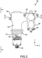
- Boom assembly 100 is shown from the vantage point 2 of FIG. 1 , with base housing 110 removed, in accordance with various embodiments.
- Boom assembly 100 includes rotary interface 122 coupled to base portion 102.
- Housing support 124 on base portion 102 is configured to support base housing 110 of FIG. 1 .
- a strain sensor 120 is coupled to flat surface 121 of boom assembly 100. Strain sensor 120 may be disposed on flat surface 121 anywhere on boom assembly 100.
- the strain sensor location may be positioned so as to tend to reduce strain imparted by rotational or twisting moment caused by the offset location of the attached rescue hoists. Thus, the strain sensor location may be in line with the greatest imparted strain in response to a load being applied to the hoist.
- strain sensor 120 is coupled to a lower portion of base portion 102 and protected by base housing 110 of FIG. 1 .
- Flat surface 121 may be formed on boom assembly 100 by, for example, milling, turning, or other machining techniques. Strain sensor 120 may be disposed in the load path of boom assembly 100 to accurately measure the load imparted to an airframe. Flat surface 121 may be precisely formed to create a surface that elastically deforms under load on boom assembly 100 and returns to the initial flat shape absent the load. Strain sensor 120 may produce an output voltage with a predetermined relationship to the load on boom assembly 100 and flat surface 121.
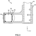
- end cap 126 may be coupled to base portion 102 of boom assembly 100.
- End cap 126 may contain signal processing electronics that are electrically coupled to strain sensor 120, as explained in greater detail below.
- end cap 126 is depicted as located in base portion 102 opposite support portion 125 in the z-direction, other locations may be suitable for signal processing electronics.
- base portion 102 may extend in the z-direction into support portion 125 for arm 104 of FIG. 1 .
- Arm 104 may extend from support portion 125 and terminate and end 105.
- Distal hoist interface 108 and proximal hoist interface 106 may thus be disposed along arm 104 between end 105 and support portion 125 of boom assembly 100.
- Boom assembly 100 may be formed from with tubular sections defining cavities.
- Base portion 102 includes walls 129 that define cavity 130. Cavity 130 may be partially opened in the z-direction towards end cap 126.
- End cap 126 may be oriented with internal components 128 disposed within cavity 130. End cap 126 may be removably fixed to base portion 102 so that internal components 128 are retained in cavity.
- Support portion 125 may extend from base portion in the z-direction and include a tubular interface extending in the x direction to interface with arm 104.
- support portion 125 may comprise a tubular section having a larger diameter than arm 104 so that arm 104 may slide into support portion 125.
- Rotary interface 122 extends from base portion 102.
- Housing support 124 on base portion 102 is configured to support base housing 110 of FIG. 1 .
- Strain sensor 120 is located on a flat segment of housing assembly and configured to measure strain in the load path.
- End cap 126 is installed in base portion 102 and arm 104 extends away from base portion 102.
- End cap 126 contains internal components 128.
- Internal components 128 may include circuitry 132 for processing signals from strain sensor 120 of FIG. 2 .
- Circuitry 132 may communicate with strain sensor 120 through plugs 134.
- Plugs 134 may be an electronic interface having one or more wire to carry a strain signal.
- circuitry 132 may include one or more electronic components 150 to process and transmit the signal from strain load sensor 152 (i.e., strain sensor 120 of FIG. 2 ) for further use.
- the signal from strain load sensor may include noise artifacts from various conditions around the sensor, and the signal may also vary in strength and characteristics in various embodiments. For example, the vibration of a helicopter in flight may manifest in the signal as the vibrations are transferred into boom assembly 100.
- Strain load sensor 152 may be in electronic communication with sensor input connector 154. Sensor input connector 154 may be, for example, plugs 134 of FIG. 5 .
- the signal from strain load sensor 152 may be passed from sensor input connector 154 into transient suppressor 156.
- Transient suppressor 156 may be, for example, a transient voltage suppressor to protect electronic components 150 from momentary voltage surges, for example.
- the signal may then be passed from transient suppressor 156 a pre-amplifier 158 to apply a gain and amplify the signal.
- the gain value may vary in various embodiments.
- the pre-amplifier 158 may apply a voltage gain value from 200-600, from 300 to 500, or about 400.
- the amplified signal may then be filtered in low-pass filter 160.
- the target frequencies of low-pass filter 160 may vary in various embodiments. For example, the low-pass filter may be tuned to -6 dB of the target frequencies.
- the signal from low-pass filter 160 may be an input into scaling network 162.
- the scaled signal from scaling network may be input to a secondary low-pass filter 164.
- Secondary low-pass filter 164 may be tuned to various frequencies in various embodiments. For example, secondary low-pass filter 164 may be tuned to -12 dB.
- the filtered output signal of secondary low-pass filter 164 may be passed to a secondary transient suppressor 166.
- the output from secondary transient suppressor 166 may be sent to an aircraft input/output connector for use by various systems in the aircraft such as, for example, a gauge or monitoring device that reports the load on boom assembly 100 (e.g., as measured in pounds, kilograms, or another readable format for an aircrew).
- secondary transient suppressor 166 may receive a power signal from the aircraft input/output connector 168 for use in signal amplification in pre-amplifier 158 and providing a reference power source for strain load sensor 152.
- aircraft input/output connector 168 may provide 28 volt power from an electronic system of an aircraft.
- Secondary transient suppressor 166 may send a signal through electromagnetic interference (EMI) filter 170.
- EMI filter 170 may provide an input signal to a DC to DC converter 172, which in turn powers DC Bus 174.
- DC bus 174 may provide a power source for the various electronic devices of boom assembly 100.
- a precision reference component 176 may produce a precision reference voltage for use in strain load sensor 152.
- the precision reference voltage may be passed through the sensor input connector 154 and into strain load sensor 152 for further use. Power from the DC bus 174 may also be used as a power source for pre-amplifier 158.
- the electronic components 150 may act as an amplifier for the strain sensor signal having an input of +/- 25mV, an output of +/- 10V, and a cutoff frequency of -5 Hz, for example.
- FIG. 7 a graph of load (in pounds) against voltage out is shown, in accordance with various embodiments.
- Data 1, Data 2, Data 3, Data 4, and Data 5 are each measured results from test runs loading boom assembly 100 with the load (represented on the y-axis) and the corresponding amplifier output voltage (represented on the x-axis).
- a linear line was fit to the data sets and is depicted to illustrate the load corresponding to a measured voltage may be loosely (relative to the quadratic function) modeled by a linear function.
- a quadratic function is also fit to the data sets and is depicted to illustrate the load corresponding to a measured voltage may be tightly (relative to the linear function) modeled by a quadratic function.
- the values of each factor in the quadratic and/or linear functions may be modified to suit the various boom assemblies 100 that may be used in various embodiments.
- the load measurement systems and methods disclosed herein may make accurate electronic measurements of the load on boom assembly 100.
- the load measurements may then be used to assess the total load on an aircraft, for example.
- the electronic components integrated into boom assembly 100 allow for strain measurement to generate an electronic strain signal and processing to convert the raw strain signal into a useable output signal representative of load on boom assembly 100.
- references to "one embodiment”, “an embodiment”, “an example embodiment”, etc. indicate that the embodiment described may include a particular feature, structure, or characteristic, but every embodiment may not necessarily include the particular feature, structure, or characteristic. Moreover, such phrases are not necessarily referring to the same embodiment. Further, when a particular feature, structure, or characteristic is described in connection with an embodiment, it is submitted that it is within the knowledge of one skilled in the art to affect such feature, structure, or characteristic in connection with other embodiments whether or not explicitly described. After reading the description, it will be apparent to one skilled in the relevant art(s) how to implement the disclosure in alternative embodiments.
Landscapes
- Engineering & Computer Science (AREA)
- Mechanical Engineering (AREA)
- Physics & Mathematics (AREA)
- General Physics & Mathematics (AREA)
- Chemical & Material Sciences (AREA)
- Analytical Chemistry (AREA)
- Measurement Of Length, Angles, Or The Like Using Electric Or Magnetic Means (AREA)
- Force Measurement Appropriate To Specific Purposes (AREA)
- Control And Safety Of Cranes (AREA)
- Forklifts And Lifting Vehicles (AREA)
- Jib Cranes (AREA)
Applications Claiming Priority (2)
| Application Number | Priority Date | Filing Date | Title |
|---|---|---|---|
| US15/069,646 US9828220B2 (en) | 2016-03-14 | 2016-03-14 | Systems and methods for detecting rescue hoist loads |
| EP17154989.2A EP3219661B1 (de) | 2016-03-14 | 2017-02-07 | Systeme zur detektion von rettungswindenlasten |
Related Parent Applications (1)
| Application Number | Title | Priority Date | Filing Date |
|---|---|---|---|
| EP17154989.2A Division EP3219661B1 (de) | 2016-03-14 | 2017-02-07 | Systeme zur detektion von rettungswindenlasten |
Publications (2)
| Publication Number | Publication Date |
|---|---|
| EP4406904A2 true EP4406904A2 (de) | 2024-07-31 |
| EP4406904A3 EP4406904A3 (de) | 2024-10-23 |
Family
ID=58017927
Family Applications (2)
| Application Number | Title | Priority Date | Filing Date |
|---|---|---|---|
| EP24181484.7A Pending EP4406904A3 (de) | 2016-03-14 | 2017-02-07 | Systeme zur erkennung von rettungswindenlasten |
| EP17154989.2A Active EP3219661B1 (de) | 2016-03-14 | 2017-02-07 | Systeme zur detektion von rettungswindenlasten |
Family Applications After (1)
| Application Number | Title | Priority Date | Filing Date |
|---|---|---|---|
| EP17154989.2A Active EP3219661B1 (de) | 2016-03-14 | 2017-02-07 | Systeme zur detektion von rettungswindenlasten |
Country Status (3)
| Country | Link |
|---|---|
| US (1) | US9828220B2 (de) |
| EP (2) | EP4406904A3 (de) |
| CA (1) | CA3255054A1 (de) |
Families Citing this family (2)
| Publication number | Priority date | Publication date | Assignee | Title |
|---|---|---|---|---|
| US12466704B2 (en) | 2022-11-14 | 2025-11-11 | Hornet Acquisitionco, Llc | Homing load detecting device for rescue hoist and winch assemblies |
| US12459793B2 (en) | 2022-11-14 | 2025-11-04 | Hornet Acquisitionco, Llc | Method to detect homing loads in rescue hoist and winch assemblies |
Family Cites Families (25)
| Publication number | Priority date | Publication date | Assignee | Title |
|---|---|---|---|---|
| DE2230546C3 (de) * | 1972-06-22 | 1982-01-21 | Magirus-Deutz Ag, 7900 Ulm | Einrichtung zur Ermittlung bzw. Anzeige der Belastung einer anziehbaren Drehleiter |
| US3809334A (en) | 1972-11-06 | 1974-05-07 | United Aircraft Corp | Winch system for helicopter |
| US3826321A (en) * | 1973-05-25 | 1974-07-30 | Trans Sonics Inc | Load weighing system for cranes with rotatable booms |
| SE396108B (sv) * | 1975-03-12 | 1977-09-05 | Akermans Verkstad Ab | Vinkelmetdon for grevarmen vid grevmaskiner |
| US4178591A (en) * | 1978-06-21 | 1979-12-11 | Eaton Corporation | Crane operating aid with operator interaction |
| DE3500891C1 (de) * | 1985-01-12 | 1986-06-26 | Krupp Mak Maschinenbau Gmbh, 2300 Kiel | Meßelement zur Ermittlung von Belastungen mit Hilfe von Schubspannungen |
| US4660729A (en) | 1985-09-16 | 1987-04-28 | Hugh E. Carbert | Method and apparatus for preventing boom overload |
| FR2667693B1 (fr) * | 1990-10-09 | 1993-01-22 | Imago | Machine pour le controle des caracteristiques de materiaux presentant une transformation de phase, reversible ou non. |
| US5331857A (en) * | 1992-08-21 | 1994-07-26 | General Automotive Specialty Co., Inc. | Pressure transducer |
| US5359516A (en) * | 1993-09-16 | 1994-10-25 | Schwing America, Inc. | Load monitoring system for booms |
| US6044991A (en) | 1995-06-21 | 2000-04-04 | Altec Industries, Inc. | Load measuring apparatus for aerial booms and jibs |
| CN1077187C (zh) * | 1996-12-12 | 2002-01-02 | 新卡特彼勒三菱株式会社 | 用于建工机械的控制装置 |
| GB9715293D0 (en) * | 1997-07-22 | 1997-09-24 | Street Crane Company Limited | Monitor and/or overload means |
| US6202013B1 (en) * | 1998-01-15 | 2001-03-13 | Schwing America, Inc. | Articulated boom monitoring system |
| NL1010355C2 (nl) * | 1998-10-20 | 2000-04-25 | Seumeren Holland Bv Van | Werkwijze voor het gebruik van een ringkraan, en ringkraan. |
| US6708926B2 (en) | 2002-05-28 | 2004-03-23 | Sikorsky Aircraft Corporation | Modular integrated self-contained cargo deployment/retrieval system |
| US6898983B2 (en) * | 2002-11-12 | 2005-05-31 | Key Energy Services, Inc. | Mechanical multiplier for a strain gage on a derrick |
| WO2004078630A2 (en) * | 2003-03-05 | 2004-09-16 | Charles Patrick De Klerk | A method of operating a hoisting device and an accessory for a hoisting device |
| US7100455B2 (en) * | 2004-08-27 | 2006-09-05 | Dresser-Nagano, Inc. | System and method for pressure measurement |
| US20100044332A1 (en) * | 2008-08-22 | 2010-02-25 | Cameron John F | Monitoring crane component overstress |
| FI122429B (fi) | 2008-12-29 | 2012-01-31 | Bronto Skylift Oy Ab | Menetelmä henkilönostimen puomin taipuman mittaamiseksi, henkilönostin sekä mittausjärjestelmä |
| US8193664B2 (en) * | 2009-11-19 | 2012-06-05 | Lien Chang Electronic Enterprise Co., Ltd. | Electrical power-saving control apparatus, power supply including that apparatus and power-saving method thereof |
| EP2332877B1 (de) * | 2009-12-08 | 2012-08-08 | Tamtron Oy | Anordnung zur Feststellung einer Eigenschaft von mittels Hebevorrichtungen manipulierten Lasten |
| WO2013040633A1 (en) * | 2011-09-20 | 2013-03-28 | Tech Mining Pty Ltd Acn 153 118 024 | Stress and/or accumulated damage monitoring system |
| WO2016007796A1 (en) | 2014-07-10 | 2016-01-14 | Breeze-Eastern Corporation | Helicopter hoist systems, devices, and methodologies |
-
2016
- 2016-03-14 US US15/069,646 patent/US9828220B2/en active Active
-
2017
- 2017-01-16 CA CA3255054A patent/CA3255054A1/en active Pending
- 2017-02-07 EP EP24181484.7A patent/EP4406904A3/de active Pending
- 2017-02-07 EP EP17154989.2A patent/EP3219661B1/de active Active
Also Published As
| Publication number | Publication date |
|---|---|
| US9828220B2 (en) | 2017-11-28 |
| CA2955120A1 (en) | 2017-09-14 |
| US20170260030A1 (en) | 2017-09-14 |
| EP3219661B1 (de) | 2024-07-03 |
| EP3219661A2 (de) | 2017-09-20 |
| EP4406904A3 (de) | 2024-10-23 |
| EP3219661A3 (de) | 2017-11-08 |
| CA3255054A1 (en) | 2025-02-25 |
Similar Documents
| Publication | Publication Date | Title |
|---|---|---|
| JP6888083B2 (ja) | 軸受の検出装置及び方法 | |
| EP1888407B1 (de) | System und verfahren zum ermitteln von hartlandungsereignissen aus trägheits- und flugzeugbezugsrahmendaten | |
| US7983854B2 (en) | Method and apparatus for monitoring a structure | |
| EP3172546B1 (de) | Ferngesteuerte und fernabgefragte drehmomentmessvorrichtungen | |
| CN105628378B (zh) | 齿轮动应力测试设备 | |
| RU2686522C2 (ru) | Способ мониторинга в режиме реального времени рабочего состояния емкостного датчика | |
| US20180162423A1 (en) | Train Coupler Structural Health Monitoring System | |
| US9828220B2 (en) | Systems and methods for detecting rescue hoist loads | |
| US7325455B2 (en) | High-temperature piezoelectric vibration sensor assembly | |
| CA2955120C (en) | Systems and methods for detecting rescue hoist loads | |
| US10890601B2 (en) | Electrical equipment for connection to a tachometer for measuring a speed of rotation of a wheel of an aircraft landing gear | |
| US12379273B2 (en) | Fastener, reader, kit, and signal acquiring method | |
| RU2654996C1 (ru) | Устройство для диагностики оборудования (измерительный канал) | |
| CN116045886A (zh) | 救援绞车缆绳角度超出检测布置 | |
| US20040035215A1 (en) | Load monitoring systems and methods | |
| CA2610835C (en) | System and method for determining aircraft hard landing events from inertial and aircraft reference frame data | |
| CN109900921A (zh) | 用于测量飞行器起落架的至少两个轮子的旋转速度的设备 | |
| CN111017238B (zh) | 一种直升机主旋翼动载荷测量装置及方法 | |
| CN224152055U (zh) | 一种动车组车内舒适性的测试装置 | |
| US12503250B2 (en) | Systems and method to determine connection of a boom with a receiver aircraft | |
| CN112526916B (zh) | 一种飞机装配型架碰撞监控方法 | |
| CN206489214U (zh) | 一种航空电磁法地面异常环感应电流采集装置 | |
| CN118323459A (zh) | 一种过载启动装置 | |
| CN114136519A (zh) | 汽车半轴动态扭矩测试系统 | |
| Sirnaik | Studies On Direct Sensor Interface Technology For Launch Vehicle Applications |
Legal Events
| Date | Code | Title | Description |
|---|---|---|---|
| PUAI | Public reference made under article 153(3) epc to a published international application that has entered the european phase |
Free format text: ORIGINAL CODE: 0009012 |
|
| STAA | Information on the status of an ep patent application or granted ep patent |
Free format text: STATUS: THE APPLICATION HAS BEEN PUBLISHED |
|
| AC | Divisional application: reference to earlier application |
Ref document number: 3219661 Country of ref document: EP Kind code of ref document: P |
|
| AK | Designated contracting states |
Kind code of ref document: A2 Designated state(s): AL AT BE BG CH CY CZ DE DK EE ES FI FR GB GR HR HU IE IS IT LI LT LU LV MC MK MT NL NO PL PT RO RS SE SI SK SM TR |
|
| REG | Reference to a national code |
Ref country code: DE Ref legal event code: R079 Free format text: PREVIOUS MAIN CLASS: B66C0013040000 Ipc: B66C0013160000 |
|
| PUAL | Search report despatched |
Free format text: ORIGINAL CODE: 0009013 |
|
| AK | Designated contracting states |
Kind code of ref document: A3 Designated state(s): AL AT BE BG CH CY CZ DE DK EE ES FI FR GB GR HR HU IE IS IT LI LT LU LV MC MK MT NL NO PL PT RO RS SE SI SK SM TR |
|
| RIC1 | Information provided on ipc code assigned before grant |
Ipc: B66C 13/04 20060101ALI20240917BHEP Ipc: G01G 19/18 20060101ALI20240917BHEP Ipc: G01L 5/00 20060101ALI20240917BHEP Ipc: B66C 23/02 20060101ALI20240917BHEP Ipc: B66C 23/90 20060101ALI20240917BHEP Ipc: B66C 23/18 20060101ALI20240917BHEP Ipc: B66C 23/16 20060101ALI20240917BHEP Ipc: B66C 13/16 20060101AFI20240917BHEP |
|
| RAP1 | Party data changed (applicant data changed or rights of an application transferred) |
Owner name: HORNET ACQUISITIONCO, LLC |
|
| STAA | Information on the status of an ep patent application or granted ep patent |
Free format text: STATUS: REQUEST FOR EXAMINATION WAS MADE |
|
| 17P | Request for examination filed |
Effective date: 20250409 |
|
| STAA | Information on the status of an ep patent application or granted ep patent |
Free format text: STATUS: EXAMINATION IS IN PROGRESS |
|
| 17Q | First examination report despatched |
Effective date: 20260212 |