EP4406903A2 - Netzladebügel mit funktionshaken - Google Patents
Netzladebügel mit funktionshaken Download PDFInfo
- Publication number
- EP4406903A2 EP4406903A2 EP24176062.8A EP24176062A EP4406903A2 EP 4406903 A2 EP4406903 A2 EP 4406903A2 EP 24176062 A EP24176062 A EP 24176062A EP 4406903 A2 EP4406903 A2 EP 4406903A2
- Authority
- EP
- European Patent Office
- Prior art keywords
- hanger body
- hanger
- aperture
- lift
- planar side
- Prior art date
- Legal status (The legal status is an assumption and is not a legal conclusion. Google has not performed a legal analysis and makes no representation as to the accuracy of the status listed.)
- Pending
Links
Images



Classifications
-
- A—HUMAN NECESSITIES
- A01—AGRICULTURE; FORESTRY; ANIMAL HUSBANDRY; HUNTING; TRAPPING; FISHING
- A01F—PROCESSING OF HARVESTED PRODUCE; HAY OR STRAW PRESSES; DEVICES FOR STORING AGRICULTURAL OR HORTICULTURAL PRODUCE
- A01F15/00—Baling presses for straw, hay or the like
- A01F15/07—Rotobalers, i.e. machines for forming cylindrical bales by winding and pressing
- A01F15/071—Wrapping devices
-
- B—PERFORMING OPERATIONS; TRANSPORTING
- B66—HOISTING; LIFTING; HAULING
- B66D—CAPSTANS; WINCHES; TACKLES, e.g. PULLEY BLOCKS; HOISTS
- B66D3/00—Portable or mobile lifting or hauling appliances
- B66D3/18—Power-operated hoists
- B66D3/26—Other details, e.g. housings
-
- A—HUMAN NECESSITIES
- A01—AGRICULTURE; FORESTRY; ANIMAL HUSBANDRY; HUNTING; TRAPPING; FISHING
- A01F—PROCESSING OF HARVESTED PRODUCE; HAY OR STRAW PRESSES; DEVICES FOR STORING AGRICULTURAL OR HORTICULTURAL PRODUCE
- A01F15/00—Baling presses for straw, hay or the like
- A01F15/07—Rotobalers, i.e. machines for forming cylindrical bales by winding and pressing
- A01F15/071—Wrapping devices
- A01F15/0715—Wrapping the bale in the press chamber before opening said chamber
-
- A—HUMAN NECESSITIES
- A01—AGRICULTURE; FORESTRY; ANIMAL HUSBANDRY; HUNTING; TRAPPING; FISHING
- A01F—PROCESSING OF HARVESTED PRODUCE; HAY OR STRAW PRESSES; DEVICES FOR STORING AGRICULTURAL OR HORTICULTURAL PRODUCE
- A01F15/00—Baling presses for straw, hay or the like
- A01F15/08—Details
-
- B—PERFORMING OPERATIONS; TRANSPORTING
- B66—HOISTING; LIFTING; HAULING
- B66C—CRANES; LOAD-ENGAGING ELEMENTS OR DEVICES FOR CRANES, CAPSTANS, WINCHES, OR TACKLES
- B66C1/00—Load-engaging elements or devices attached to lifting or lowering gear of cranes or adapted for connection therewith for transmitting lifting forces to articles or groups of articles
- B66C1/10—Load-engaging elements or devices attached to lifting or lowering gear of cranes or adapted for connection therewith for transmitting lifting forces to articles or groups of articles by mechanical means
- B66C1/12—Slings comprising chains, wires, ropes, or bands; Nets
- B66C1/16—Slings with load-engaging platforms or frameworks
-
- B—PERFORMING OPERATIONS; TRANSPORTING
- B66—HOISTING; LIFTING; HAULING
- B66D—CAPSTANS; WINCHES; TACKLES, e.g. PULLEY BLOCKS; HOISTS
- B66D3/00—Portable or mobile lifting or hauling appliances
- B66D3/18—Power-operated hoists
- B66D3/20—Power-operated hoists with driving motor, e.g. electric motor, and drum or barrel contained in a common housing
Definitions
- the disclosure generally relates to a lift system and a hanger for a baler implement.
- a baler implement gathers crop material and forms the crop material into a baler.
- the baler implement may be configured as a round baler, which forms the bale into a bale having a cylindrical shape.
- the baler implement may include a wrap system that is operable to wrap or encircle the bale with a wrap material.
- the wrap material generally may be supplied on a roll, which is loaded into the wrap system.
- the baler implement may include a roll lift system for lifting the roll of the wrap material into the wrap system.
- the lift system may include a hanger attached to a lift line, with the lift line attached to a line actuator for raising and lowering the hanger.
- the hanger When not in use, the hanger must be stored. Due to the height of the wrap system, the hanger may be positioned at a height above ground that is difficult for some users to reach, thereby making it difficult for these users to attach and/or detach the hanger.
- a lift system for loading a roll of wrap material into a wrap system of a baler implement includes a line actuator that is configured for attachment to a structure of the baler implement.
- a hanger includes a hanger body having a first planar side and an opposing second planar side. The hanger body defines a first aperture extending through the hanger body, between the first planar side and the second planar side. The first aperture is positioned such that a center of gravity of the hanger body is located within the first aperture.
- a lift line includes an upper end portion that is secured to the line actuator. The lift line is retractable into the line actuator in response to movement of the line actuator in a first direction.
- the lift line is extendable out of the line actuator in response to movement of the line actuator in a second direction.
- the lift line includes a lower end portion supporting the hanger. The lower end portion of the lift line passes through the first aperture such that the lift line applies a lift force to the hanger body at the center of gravity of the hanger body.
- the line actuator may raise the hanger to a storage position in which the lift line is fully retracted and the hanger is brought into engagement with structure of the baler implement. Because the lift line applies the lift force at the center of gravity of the hanger body, the hanger will naturally come to rest against the structure with one of the first planar side or the second planar side of the hanger body flat against the structure, thereby securing the hanger tightly against the structure for storage. Tension of the lift line maintains the hanger in storage position. Because the hanger rests flat against the structure, and is tensioned against the structure by the lift line, the hanger may remain stationary in the storage position. As such, the lift system described herein provides for storage of the hanger without the user having to reattach the hanger from the lift line and/or detach the hanger from the lift line before or after use.
- the lift line includes a central portion disposed between the upper end portion and the lower end portion of the lift line.
- a connection secures the lower end portion to the central portion thereby forming a loop portion of the lift line, which supports the hanger.
- the loop portion of the lift line passes through the first aperture.
- connection may include one of a sewn connection or a mechanical fastener.
- connection includes a tri-glide fastener.
- connection may include other types of mechanical fasteners not mentioned or described herein.
- the hanger body defines a second aperture extending through the hanger body, between the first planar side and the second planar side.
- the hanger body includes an upper edge and an opposing lower edge.
- the second aperture is positioned vertically below the center of gravity when the hanger body is arranged in an upright position.
- the upright position is defined as an orientation of the hanger body in which the first planar side and the second planar side are vertical, with the upper edge of the hanger body disposed above the lower edge of the hanger body.
- the second aperture is positioned vertically below the first aperture when the hanger body is arranged with the first planar side and the second planar side vertical and with the upper edge vertically above the lower edge.
- the lift line follows a lashing path to secure the hanger to the lift line.
- the lashing path passes the lift line from the first planar side to the second planar side through the first aperture, positions the lift line adjacent the second planar side between the first aperture and the second aperture, passes the lift line from the second planar side to the first planar side through the second aperture, positions the lift line adjacent the first planar side between the second aperture and the lower edge of the hanger body, wraps the lift line from the first planar side around the lower edge of the hanger body to the second planar side, positions the lift line on the second planar side of the hanger body between the lower edge of the hanger body and the first aperture, and passes the lift line from the second planar side to the first planar side through the first aperture, whereby the connection may secure the lower end portion of the lift line to the central portion of the lift line.
- the hanger body may define a third aperture extending through the hanger body, between the first planar side and the second planar side.
- the third aperture is positioned vertically above the center of gravity when the hanger body is arranged in the upright position.
- the third aperture may be used for an alternative lashing path of the lift line if desired.
- the lift line may include one of, but is not limited to, a generally circular cross-sectional shape or a generally flat cross sectional shape.
- the lift line may include a substantially flat strap of nylon webbing material.
- the first aperture may include a shape corresponding to a cross-sectional shape of the lift line.
- the first aperture may include an elongated slot having a long axis extending parallel with a long dimension of the hanger, and shaped to correspond to the generally rectangular cross-sectional shape of the lift line.
- the second aperture may include a shape corresponding to the cross-sectional shape of the lift line and substantially identical to the shape of the first aperture.
- the hanger body includes an upper edge and an opposing lower edge each extending between a first longitudinal end and a second longitudinal end of the hanger body.
- the upper edge of the hanger body defines a first pocket disposed proximate the first longitudinal end of the hanger body.
- the upper edge of the hanger body defines a second pocket disposed proximate the second longitudinal end of the hanger body.
- each of the first pocket and the second pocket may be shaped to receive a respective lifting band of the roll of wrap material therein.
- the first pocket may be shaped to include sides extending vertically when the hanger is arranged in the upright position to capture a respective lifting band of the roll of wrap material therebetween, such that the lifting band is restricted against lateral movement off the first longitudinal end of the hanger.
- the second pocket may be shaped to include sides extending vertically when the hanger is arranged in the upright position to capture a respective lifting band of the roll of wrap material therebetween, such that the lifting band is restricted against lateral movement off the second longitudinal end of the hanger.
- each of the first pocket and the second pocket may include an opening defining an opening width along the upper edge of the hanger.
- Each of the first pocket and the second pocket may include an interior for securing the respective lifting band therein, wherein the interior of each of the first pocket and the second pocket defines an interior width along the upper edge of the hanger.
- the opening width is less than the interior width.
- the first pocket may include a respective outer lip partially covering an outer edge of the first pocket, and a respective inner lip partially covering an inner edge of the first pocket.
- the second pocket may include a respective outer lip partially covering an outer edge of the second pocket, and a respective inner lip partially covering an inner edge of the second pocket.
- the first pocket and the second pocket are spaced equidistant from the center of gravity of the hanger body along a long dimension and/or a central longitudinal axis of the hanger body.
- the first pocket and the second pocket each include a respective engagement surface positioned vertically below the first aperture, i.e., vertically below the center of gravity when the hanger is level, when the hanger body is arranged in the upright position with the upper edge positioned vertically above the lower edge.
- a hanger for a net wrap lift system of a baler implement comprising a hanger body having an upper edge and an opposing lower edge, with a first planar side and an opposing second planar side extending between the upper edge and the lower edge; wherein the hanger body defines a first aperture extending through the hanger body between the first planar side and the second planar side, with the first aperture positioned such that a center of gravity of the hanger body is located within the first aperture; and wherein the hanger body defines a second aperture extending through the hanger body between the first planar side and the second planar side, with the second aperture positioned vertically below the first aperture when the hanger body is arranged in an upright position with the upper edge of the hanger body positioned vertically above the lower edge of the hanger body.
- the upper edge and the opposing lower edge of the hanger body each extend between a first longitudinal end and a second longitudinal end of the hanger body, wherein the upper edge of the hanger body defines a first pocket disposed proximate the first longitudinal end of the hanger body, and wherein the upper edge of the hanger body defines a second pocket disposed proximate the second longitudinal end of the hanger body.
- the first pocket is shaped to include sides extending vertically when the hanger is arranged in an upright position to capture a respective lifting band of the roll of wrap material therebetween, such that the lifting band is restricted against lateral movement off the first longitudinal end of the hanger
- the second pocket is shaped to include sides extending vertically when the hanger is arranged in an upright position to capture a respective lifting band of the roll of wrap material therebetween, such that the lifting band is restricted against lateral movement off the second longitudinal end of the hanger.
- each of the first pocket and the second pocket includes an opening defining an opening width along the upper edge of the hanger, and wherein each of the first pocket and the second pocket include an interior for securing a respective lifting band therein, wherein the interior of each of the first pocket and the second pocket defines an interior width along the upper edge of the hanger, with the opening width less than the interior width.
- the first pocket includes a respective outer lip partially covering an outer edge of the first pocket and a respective inner lip partially covering an inner edge of the first pocket
- the second pocket includes a respective outer lip partially covering an outer edge of the second pocket and a respective inner lip partially covering an inner edge of the second pocket
- first pocket and the second pocket are spaced equidistant from the center of gravity of the hanger body.
- first pocket and the second pocket each include a respective engagement surface positioned vertically below the first aperture when the hanger body is arranged in an upright position with the upper edge positioned vertically above the lower edge.
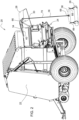
- baler implement 20 is generally shown at 20.
- the baler implement 20 is configured to produce a bale having a cylindrical shape, and may be referred to as a round baler.
- the baler implement 20 may be configured differently than described herein, and that the teachings of the disclosure may apply to implements other than the round baler described herein.
- the baler implement 20 accumulates cut crop material, and forms the accumulated crop material into a bale.
- the bale has a cylindrical shape, and may be referred to as a round bale.
- the baler implement 20 accumulates the crop material in a bale forming chamber, wherein the baler implement 20 forms the crop material into the round bale.
- the manner, process, and/or features used to form the crop material into the round bale in the bale forming chamber are known to those skilled in the art, are not pertinent to the teachings of this disclosure, and are therefore not described in detail herein.
- the baler implement 20 includes an implement body 22.
- the implement body 22 may include one or more panels that form an exterior surface of the baler implement 20, as well as the frame and other support members that support the panels and other components of the baler implement 20.
- the baler implement 20 includes a wrap system 24 that is attached to the implement body 22.
- the wrap system 24 includes a roll of wrap material 26 that is supported relative to the implement body 22 in an installed position 32.
- the roll of wrap material 26 includes a width that is substantially equal to, or perhaps slightly larger than, a height (or length) of the round bale.
- the wrap material may include a film, mesh, net, or other material suitable for wrapping around a circumference of the round bale to secure the shape and/or form of the round bale, and/or to protect the round bale from moisture intrusion.
- the wrap material may include, but is not limited to, a net or a plastic film that is wound around the circumference of the round bale.
- the wrap system 24 is configured for wrapping the wrap material around the formed round bale in the bale forming chamber of the baler implement 20. As such, the wrap system 24 un-winds the wrap material from the roll of wrap material 26 and feeds the wrap material into the bale forming chamber, where the wrap material is wound around the circumference of the round bale.
- the specific manner in which the wrap system 24 un-winds the wrap material, feeds the wrap material into the bale forming chamber, and wraps the wrap material around the round bale within the bale forming chamber is not pertinent to the teachings of this disclosure, are known to those skilled in the art, and are therefore not described in detail herein.
- a cover 28 is moveably attached to the implement body 22.
- the cover 28 is moveable between a closed position, shown in FIG. 1 , and an open position, shown in FIG. 2 .
- the cover 28 When the cover 28 is disposed in the open position, the cover 28 provides access to the wrap system 24 from an exterior location of the baler implement 20.
- the exterior location may include, for example, a location an operator may stand when loading the roll of wrap material 26 into the wrap system 24, or otherwise servicing the wrap system 24.
- the cover 28 When the cover 28 is disposed in the closed position, the cover 28 encloses the wrap system 24 from the exterior location.
- the implement body 22 and the cover 28 cooperate to form a wrap chamber therebetween, wherein the roll of the wrap material is positioned when in the installed position 32.
- the wrap chamber is generally closed or sealed to prevent or limit dust, dirt, debris, and moisture from contacting the wrap system 24, including the roll of wrap material 26.
- the exemplary implementation of the baler implement 20 includes the cover 28 rotatable about a horizontal axis, such that the cover 28 moves in an upward and/or downward motion relative to the implement body 22, whereby the cover 28 is positioned vertically above the wrap system 24 when disposed in the open position.
- the cover 28 may rotate about a vertical axis, such that the cover 28 moves in a side-to-side motion, whereby the cover 28 is positioned to a side of the baler implement 20 when positioned in the open position.
- the baler implement 20 further includes a lift system 30.
- the lift system 30 is operable to raise the roll of wrap material 26, relative to the implement body 22, into the installed position 32.
- the lift system 30 is attached to one of the implement body 22 and the cover 28.
- the lift system 30 When the cover 28 is disposed in the closed position, such as shown in FIG. 1 , the lift system 30 is concealed between the implement body 22 and the cover 28, within the wrap chamber.
- the lift system 30 may be accessed by moving the cover 28 into the open position, such as shown in FIG. 2 .
- the lift system 30 is positioned below the cover 28. However, as noted above, if the cover 28 moves to the side when opened, then the lift system 30 would not be positioned below the cover 28.
- the lift system 30 includes a lift location, or a lift point.
- the lift location is the location from which a vertical force is applied to one or more components of the baler implement 20 in order to raise the roll of wrap material 26.
- the lift location is positionable at an elevation disposed above the installed position 32 of the roll of wrap material 26.
- the lift location is located vertically above the installed position 32 of the roll of wrap material 26 so that the roll may be fully lifted into the installed position 32.
- the lift system 30 may include a line actuator 34 having a lift line 36.
- the lift line 36 extends from the lift location downward for engagement with the roll of wrap material 26.
- the lift line 36 may include, but is not limited to, a cable, a rope, a chain, a strap, etc.
- the lift line 36 includes or is attached to a hanger 38 for engaging lifting bands 88 associated with the roll of wrap material 26.
- the line actuator 34 may include a mechanism capable of retracting and extending the lift line 36 in order to raise and lower the roll of wrap material 26.
- the line actuator 34 may include a winding device having a rotatable member that is rotatable about an axis, and that is capable of winding and unwinding the lift line 36 in order to raise and lower the roll of wrap material 26.
- the line actuator 34 may include, but is not limited to, an electrically driven winch or a manually operated winch that winds and unwinds the lift line 36 to raise and lower the roll.
- the lift system 30 may include a device other than the exemplary embodiments of the line actuator 34 described herein for raising the roll of wrap material 26.
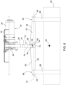
- the lift system 30 may include a lift structure 40.
- the lift structure 40 may be directly attached to the cover 28 to define the lift location, such as shown in FIGS. 2 and 6 .
- the lift structure 40 may be attached to other structural components of the implement body 22.
- the example implementation of the lift system 30 includes the line actuator 34 directly attached to the lift structure 40, which is in turn attached to the cover 28.
- the line actuator 34 may be extended to lower the lift line 36 for attachment to the roll of wrap material 26 at a lower elevation. Once the lift line 36 is attached to the roll of wrap material 26, the line actuator 34 may be retracted, e.g., wound, to raise the roll of wrap material 26 into the installed position 32 in the wrap system 24.
- the hanger 38 includes a hanger body 42.
- the hanger body 42 is a generally planar structure.
- the hanger body 42 extends along a central longitudinal axis 44 between a first longitudinal end 46 and a second longitudinal end 48.
- the hanger body 42 includes an upper edge 50 and a lower edge 52 both extending between the first longitudinal end 46 and the second longitudinal end 48.
- the first longitudinal end 46, the second longitudinal end 48, the upper edge 50, and the lower edge 52 all exhibit a thickness 54 of the hanger body 42.
- the hanger body 42 further includes a first planar side 56 and an opposing second planar side 58.
- the first planar side 56 and the second planar side 58 extend longitudinal along the central longitudinal axis 44 between the first longitudinal end 46 and the second longitudinal end 48.
- the first planar side 56 and the second planar side 58 also extend laterally between the upper edge 50 and the lower edge 52.
- the hanger body 42 defines a first aperture 60.
- the first aperture 60 extends through the hanger body 42, between the first planar side 56 and the second planar side 58.
- the first aperture 60 is positioned such that a center of gravity 62 of the hanger body 42 is located within the first aperture 60.
- the hanger body 42 further defines a second aperture 64.
- the second aperture 64 extends through the hanger body 42, between the first planar side 56 and the second planar side 58.
- the second aperture 64 is positioned vertically below the first aperture 60 and below the center of gravity 62 of the hanger body 42 when the hanger body 42 is arranged in an upright position.
- the upright position is defined as an orientation of the hanger body 42 in which the first planar side 56 and the second planar side 58 are vertical, with the upper edge 50 of the hanger body 42 disposed above the lower edge 52 of the hanger body 42.
- the second aperture 64 is positioned vertically below the first aperture 60 when the hanger body 42 is arranged with the first planar side 56 and the second planar side 58 vertical and with the upper edge 50 vertically above the lower edge 52.
- the lift line 36 has an upper end portion 66, a lower end portion 68, and a central portion 70.
- the upper end portion 66 is secured to the line actuator 34.
- the upper end portion 66 is secured to the rotatable member of the line actuator 34.
- the lift line 36 is retractable into the line actuator 34 in response to movement of the line actuator 34 in a first direction, e.g., rotation of the rotatable member in a first rotational direction.
- the lift line 36 is extendable out of the line actuator 34 in response to movement of the line actuator 34 in a second direction, e.g., rotation of the rotatable member in a second rotational direction.
- the lower end portion 68 of the lift line 36 is attached to and/or supports the hanger 38.
- the lower end portion 68 of the lift line 36 passes through the first aperture 60 such that the lift line 36 applies a lift force to the hanger body 42 at the first aperture 60, i.e., at the center of gravity 62 of the hanger body 42.
- the central portion 70 of the lift line 36 is disposed between the upper end portion 66 and the lower end portion 68 of the lift line 36.
- the lift line 36 may further include a connection 72 securing the lower end portion 68 to the central portion 70, thereby forming a loop portion 74 of the lift line 36.
- the hanger 38 may be supported by the loop portion 74 of the lift line 36.
- connection 72 between the lower end portion 68 and the central portion 70 of the lift line 36 may include, but is not limited to, one of a sewn connection 72 or a mechanical fastener 76. If the connection 72 is made via a mechanical fastener 76, the connection 72 may include, but is not limited to, a tri-glide fastener, a D-ring, buckle, cam lock, or some other type of fastener capable of securing strap or cable.
- the lift line 36 may include, but is not limited to, a generally rectangular cross-sectional shape, or a generally circular cross-sectional shape.
- the first aperture 60 and the second aperture 64 are sized and shaped to correspond to the cross-sectional shape of the lift line 36.
- the lift line 36 is implemented as a substantially flat strap, such as but not limited to flexible nylon strap, having a generally rectangular cross-sectional shape.
- the first aperture 60 and the second aperture 64 are shaped to correspond with the generally rectangular cross-sectional shape of the strap.
- first aperture 60 and the second aperture 64 are each implemented as elongated slots having a shape and size to match the generally rectangular cross-sectional shape of the lift line 36, and having a long axis 78 extending parallel with the central longitudinal axis 44 and/or the long dimension of the hanger body 42.
- the lower end portion 68 of the lift line 36 may be secured to the central portion 70 of the lift line 36 to form the loop portion 74 of the lift line 36.
- the loop portion 74 of the lift line 36 passes through the first aperture 60.
- the lift line 36 follows a lashing path 80 to secure the hanger 38 to the lift line 36.
- the lashing path 80 passes the lift line 36 from the first planar side 56 to the second planar side 58 through the first aperture 60, positions the lift line 36 adjacent the second planar side 58 between the first aperture 60 and the second aperture 64, passes the lift line 36 from the second planar side 58 to the first planar side 56 through the second aperture 64, positions the lift line 36 adjacent the first planar side 56 between the second aperture 64 and the lower edge 52 of the hanger body 42, wraps the lift line 36 from the first planar side 56 around the lower edge 52 of the hanger body 42 to the second planar side 58, positions the lift line 36 adjacent the second planar side 58 between the lower edge 52 of the hanger body 42 and the first aperture 60, and passes the lift line 36 from the second planar side 58 to the first planar side 56 through the first aperture 60, whereby the lower end portion 68 of the lift line 36 may be attached to the central portion 70 of the lift line
- the lift line 36 applies the lifting force to the hanger body 42 at the first aperture 60, i.e., the center of gravity 62 of the hanger body 42, from the first planar side 56 of the hanger body 42.
- This configuration enables the hanger 38 to be drawn up snugly against the lift structure 40 and held with the first planar side 56 of the hanger body 42 resting flat against the lift structure 40 when the lift line 36 is retracted into the line actuator 34, such as shown in FIG. 7 and in phantom in FIG. 6 .
- the hanger 38 may be conveniently stored tight against the lift structure 40 when not in use, and held in place via tension in the lift line 36 applied via the line actuator 34.
- the lashing path 80 described above may be reversed to position the second planar side 58 of the hanger 38 against the lift structure 40.
- the hanger body 42 may further define a third aperture 82.
- the third aperture 82 extends through the hanger body 42 between the first planar side 56 and the second planar side 58.
- the third aperture 82 is positioned vertically above the center of gravity 62 when the hanger body 42 is arranged in an upright position.
- the third aperture 82 permits the lift line 36 to be routed using an alternative configuration if desired.
- the upper edge 50 of the hanger body 42 defines a first pocket 84 disposed proximate the first longitudinal end 46 of the hanger body 42, and a second pocket 86 disposed proximate the second longitudinal end 48 of the hanger body 42.
- the first pocket 84 and the second pocket 86 are spaced equidistant from the center of gravity 62 of the hanger body 42, along the central longitudinal axis 44 of the hanger body 42.
- Each of the first pocket 84 and the second pocket 86 are shaped to receive a respective lifting band 88 of the roll of wrap material 26 therein for raising the roll of the wrap material.
- the first pocket 84 and the second pocket 86 may each include a respective engagement surface 90 that is positioned vertically below the first aperture 60 when the hanger body 42 is arranged in the upright position, with the upper edge 50 positioned vertically above the lower edge 52.
- the combined center of gravity 92 of the hanger 38 and the roll of wrap material 26 is below the first aperture 60.
- This configuration in which the engagement surface 90s are positioned below the first aperture 60, causes the hanger 38 to rotate into the upright position while raising the roll of the wrap material.
- the center of gravity 62 of the hanger 38 aligns with the first aperture 60, thereby enabling the hanger 38 to lay flat such that the hanger 38 may be positioned flat against the lift structure 40 when raised into the storage position.
- the first pocket 84 may be shaped to include pocket sides 94 extending vertically when the hanger 38 is arranged in the upright position to capture its respective lifting band 88 of the roll of wrap material 26 therebetween, such that the lifting band 88 is restricted against lateral movement off the first longitudinal end 46 of the hanger 38.
- the second pocket 86 may be shaped to include pocket sides 94 extending vertically when the hanger 38 is arranged in the upright position to capture a respective lifting band 88 of the roll of wrap material 26 therebetween, such that the lifting band 88 is restricted against lateral movement off the second longitudinal end 48 of the hanger 38.
- each of the first pocket 84 and the second pocket 86 includes an opening 96 defining an opening width 98 along the upper edge 50 of the hanger 38.
- Each of the first pocket 84 and the second pocket 86 include an interior 100 for securing the respective lifting band 88 therein.
- the interior 100 of each of the first pocket 84 and the second pocket 86 defines an interior width 102 along the upper edge 50 of the hanger 38.
- the opening width 98 may be less than the interior width 102 to restrict the lifting bands 88 from dislodging from the interior 100 of the first pocket 84 and the second pocket 86 respectively.
- the first pocket 84 may include a respective outer lip 104 partially covering an outer edge 108 of the first pocket 84, and a respective inner lip 106 partially covering an inner edge 110 of the first pocket 84.
- the inner lip 106 and the outer lip 104 of the first pocket 84 operate to capture the respective lifting band 88 therein to prevent the lifting band 88 from dislodging from the first pocket 84.
- the second pocket 86 may include a respective outer lip 112 partially covering an outer edge 116 of the second pocket 86 and a respective inner lip 114 partially covering an inner edge 118 of the second pocket 86.
- the inner lip 114 and the outer lip 112 of the second pocket 86 operate to capture the respective lifting band 88 therein to prevent the lifting band 88 from dislodging from the second pocket 86.
- baler implement 20 shown in the Figures and described herein shows the wrap system 24 and the lift system 30 located at the rearward end of the baler implement 20.
- the teachings of this disclosure may be applied to implementations of the baler implement 20 in which the wrap system 24, the lift system 30 and the cover 28 are located at the forward end of the baler implement 20.
Landscapes
- Engineering & Computer Science (AREA)
- Mechanical Engineering (AREA)
- Life Sciences & Earth Sciences (AREA)
- Environmental Sciences (AREA)
- Load-Engaging Elements For Cranes (AREA)
- Packaging Of Machine Parts And Wound Products (AREA)
Applications Claiming Priority (3)
| Application Number | Priority Date | Filing Date | Title |
|---|---|---|---|
| US202263267222P | 2022-01-27 | 2022-01-27 | |
| US18/048,872 US12234134B2 (en) | 2022-01-27 | 2022-10-24 | Net loading hanger with functional hooks |
| EP23152072.7A EP4218399B1 (de) | 2022-01-27 | 2023-01-17 | Hubsystem zum beladen einer wickelmaterialrolle mit hänger mit funktionshaken |
Related Parent Applications (2)
| Application Number | Title | Priority Date | Filing Date |
|---|---|---|---|
| EP23152072.7A Division-Into EP4218399B1 (de) | 2022-01-27 | 2023-01-17 | Hubsystem zum beladen einer wickelmaterialrolle mit hänger mit funktionshaken |
| EP23152072.7A Division EP4218399B1 (de) | 2022-01-27 | 2023-01-17 | Hubsystem zum beladen einer wickelmaterialrolle mit hänger mit funktionshaken |
Publications (2)
| Publication Number | Publication Date |
|---|---|
| EP4406903A2 true EP4406903A2 (de) | 2024-07-31 |
| EP4406903A3 EP4406903A3 (de) | 2025-02-26 |
Family
ID=84981924
Family Applications (2)
| Application Number | Title | Priority Date | Filing Date |
|---|---|---|---|
| EP23152072.7A Active EP4218399B1 (de) | 2022-01-27 | 2023-01-17 | Hubsystem zum beladen einer wickelmaterialrolle mit hänger mit funktionshaken |
| EP24176062.8A Pending EP4406903A3 (de) | 2022-01-27 | 2023-01-17 | Netzladebügel mit funktionshaken |
Family Applications Before (1)
| Application Number | Title | Priority Date | Filing Date |
|---|---|---|---|
| EP23152072.7A Active EP4218399B1 (de) | 2022-01-27 | 2023-01-17 | Hubsystem zum beladen einer wickelmaterialrolle mit hänger mit funktionshaken |
Country Status (2)
| Country | Link |
|---|---|
| US (1) | US12234134B2 (de) |
| EP (2) | EP4218399B1 (de) |
Family Cites Families (6)
| Publication number | Priority date | Publication date | Assignee | Title |
|---|---|---|---|---|
| JPS557128A (en) * | 1978-06-26 | 1980-01-18 | Katayama Kiyoharu | Crane hanging metal tool |
| US7430959B2 (en) | 2006-11-23 | 2008-10-07 | Elgin Routledge | Device for lifting bale wrapping rolls |
| CN103818824A (zh) * | 2013-12-14 | 2014-05-28 | 河南机电高等专科学校 | 一种可翻转h型钢吊运装置 |
| CA3026362A1 (en) * | 2017-12-04 | 2019-06-04 | Vermeer Manufacturing Company | Wrap material transfer device |
| US10820527B2 (en) | 2018-07-13 | 2020-11-03 | Deere & Company | Baler with netwrap roll loading device |
| US10934143B2 (en) | 2018-07-13 | 2021-03-02 | Deere & Company | Net wrap lifting device |
-
2022
- 2022-10-24 US US18/048,872 patent/US12234134B2/en active Active
-
2023
- 2023-01-17 EP EP23152072.7A patent/EP4218399B1/de active Active
- 2023-01-17 EP EP24176062.8A patent/EP4406903A3/de active Pending
Also Published As
| Publication number | Publication date |
|---|---|
| EP4218399B1 (de) | 2025-08-13 |
| EP4406903A3 (de) | 2025-02-26 |
| US20230234818A1 (en) | 2023-07-27 |
| EP4218399A2 (de) | 2023-08-02 |
| US12234134B2 (en) | 2025-02-25 |
| EP4218399A3 (de) | 2023-11-29 |
Similar Documents
| Publication | Publication Date | Title |
|---|---|---|
| US6550841B1 (en) | Tailgate nested tailgate bed extender | |
| US4784427A (en) | Enclosure assembly for open bed vehicle | |
| US5549347A (en) | All weather mechanically reciprocatable roll top cover apparatus | |
| US6461090B1 (en) | Stowable cargo restraining barrier assembly and method | |
| US20050212322A1 (en) | Retractable car cover | |
| US11299379B2 (en) | Net wrap lifting device | |
| US8919085B2 (en) | Net roll support for storage and installation in baler | |
| US20120217762A1 (en) | Vehicle tie-down device for hauling a load | |
| US3222102A (en) | Vehicle cover | |
| US4148516A (en) | Means for automatically opening rear storage compartment cover of an automobile | |
| EP4406903A2 (de) | Netzladebügel mit funktionshaken | |
| CA2498069C (en) | Sun shade apparatus for a vehicle | |
| US5567002A (en) | Vehicle cover and tent device | |
| KR100907667B1 (ko) | 암롤 트럭의 적재함 덮개장치 | |
| EP2024233B1 (de) | Bindegarnrollenlagerung für ballenpressen | |
| US8573119B2 (en) | Round baler | |
| JP2863488B2 (ja) | 荷物運搬車両の荷台のカバー装置 | |
| US12382872B2 (en) | Net wrap roll with lift hook location markings | |
| US6332473B1 (en) | Apparatus for horse trailer | |
| CA2366149C (en) | Tailgate nested tailgate bed extender | |
| US20240300400A1 (en) | Cover assembly for cargo area of a fire truck | |
| US5295501A (en) | Circus tent | |
| CN219541304U (zh) | 一种施工用环保防尘网 | |
| CN213706535U (zh) | 软开顶集装箱 | |
| CN212555789U (zh) | 一种轻便型多用途汽车帐装置 |
Legal Events
| Date | Code | Title | Description |
|---|---|---|---|
| PUAI | Public reference made under article 153(3) epc to a published international application that has entered the european phase |
Free format text: ORIGINAL CODE: 0009012 |
|
| STAA | Information on the status of an ep patent application or granted ep patent |
Free format text: STATUS: THE APPLICATION HAS BEEN PUBLISHED |
|
| AC | Divisional application: reference to earlier application |
Ref document number: 4218399 Country of ref document: EP Kind code of ref document: P |
|
| AK | Designated contracting states |
Kind code of ref document: A2 Designated state(s): AL AT BE BG CH CY CZ DE DK EE ES FI FR GB GR HR HU IE IS IT LI LT LU LV MC ME MK MT NL NO PL PT RO RS SE SI SK SM TR |
|
| REG | Reference to a national code |
Ref country code: DE Ref legal event code: R079 Free format text: PREVIOUS MAIN CLASS: B66C0001160000 Ipc: A01F0015070000 |
|
| PUAL | Search report despatched |
Free format text: ORIGINAL CODE: 0009013 |
|
| AK | Designated contracting states |
Kind code of ref document: A3 Designated state(s): AL AT BE BG CH CY CZ DE DK EE ES FI FR GB GR HR HU IE IS IT LI LT LU LV MC ME MK MT NL NO PL PT RO RS SE SI SK SM TR |
|
| RIC1 | Information provided on ipc code assigned before grant |
Ipc: B66C 1/16 20060101ALI20250117BHEP Ipc: A01F 15/07 20060101AFI20250117BHEP |
|
| STAA | Information on the status of an ep patent application or granted ep patent |
Free format text: STATUS: REQUEST FOR EXAMINATION WAS MADE |
|
| 17P | Request for examination filed |
Effective date: 20250826 |