EP4406831A1 - Spoiler - Google Patents
Spoiler Download PDFInfo
- Publication number
- EP4406831A1 EP4406831A1 EP24153238.1A EP24153238A EP4406831A1 EP 4406831 A1 EP4406831 A1 EP 4406831A1 EP 24153238 A EP24153238 A EP 24153238A EP 4406831 A1 EP4406831 A1 EP 4406831A1
- Authority
- EP
- European Patent Office
- Prior art keywords
- wing
- spoiler
- aircraft
- pop
- actuation mechanism
- Prior art date
- Legal status (The legal status is an assumption and is not a legal conclusion. Google has not performed a legal analysis and makes no representation as to the accuracy of the status listed.)
- Pending
Links
Images

Classifications
-
- B—PERFORMING OPERATIONS; TRANSPORTING
- B64—AIRCRAFT; AVIATION; COSMONAUTICS
- B64C—AEROPLANES; HELICOPTERS
- B64C9/00—Adjustable control surfaces or members, e.g. rudders
- B64C9/14—Adjustable control surfaces or members, e.g. rudders forming slots
- B64C9/146—Adjustable control surfaces or members, e.g. rudders forming slots at an other wing location than the rear or the front
-
- B—PERFORMING OPERATIONS; TRANSPORTING
- B64—AIRCRAFT; AVIATION; COSMONAUTICS
- B64C—AEROPLANES; HELICOPTERS
- B64C3/00—Wings
- B64C3/58—Wings provided with fences or spoilers
-
- B—PERFORMING OPERATIONS; TRANSPORTING
- B64—AIRCRAFT; AVIATION; COSMONAUTICS
- B64C—AEROPLANES; HELICOPTERS
- B64C9/00—Adjustable control surfaces or members, e.g. rudders
- B64C9/32—Air braking surfaces
- B64C9/323—Air braking surfaces associated with wings
-
- B—PERFORMING OPERATIONS; TRANSPORTING
- B64—AIRCRAFT; AVIATION; COSMONAUTICS
- B64C—AEROPLANES; HELICOPTERS
- B64C13/00—Control systems or transmitting systems for actuating flying-control surfaces, lift-increasing flaps, air brakes, or spoilers
- B64C13/24—Transmitting means
- B64C13/26—Transmitting means without power amplification or where power amplification is irrelevant
- B64C13/28—Transmitting means without power amplification or where power amplification is irrelevant mechanical
-
- B—PERFORMING OPERATIONS; TRANSPORTING
- B64—AIRCRAFT; AVIATION; COSMONAUTICS
- B64C—AEROPLANES; HELICOPTERS
- B64C5/00—Stabilising surfaces
- B64C5/08—Stabilising surfaces mounted on, or supported by, wings
-
- B—PERFORMING OPERATIONS; TRANSPORTING
- B64—AIRCRAFT; AVIATION; COSMONAUTICS
- B64C—AEROPLANES; HELICOPTERS
- B64C9/00—Adjustable control surfaces or members, e.g. rudders
- B64C9/02—Mounting or supporting thereof
-
- B—PERFORMING OPERATIONS; TRANSPORTING
- B64—AIRCRAFT; AVIATION; COSMONAUTICS
- B64C—AEROPLANES; HELICOPTERS
- B64C9/00—Adjustable control surfaces or members, e.g. rudders
- B64C9/32—Air braking surfaces
-
- B—PERFORMING OPERATIONS; TRANSPORTING
- B64—AIRCRAFT; AVIATION; COSMONAUTICS
- B64C—AEROPLANES; HELICOPTERS
- B64C9/00—Adjustable control surfaces or members, e.g. rudders
- B64C9/34—Adjustable control surfaces or members, e.g. rudders collapsing or retracting against or within other surfaces or other members
-
- B—PERFORMING OPERATIONS; TRANSPORTING
- B64—AIRCRAFT; AVIATION; COSMONAUTICS
- B64C—AEROPLANES; HELICOPTERS
- B64C30/00—Supersonic type aircraft
Definitions
- the present invention relates to an aircraft wing with a pop-up spoiler unit.
- Aircraft wing spoilers are used to disrupt lift produced by the wing and also increase drag. They are moveable between a retracted and a deployed position. Traditional spoilers for large aircraft are mounted on the upper wing surface near the wing trailing edge, often just forward of trailing edge flaps, and are deployed by rotating upwardly into the oncoming airflow.
- Aircraft wings are subject to bending load deflections and this can present challenges for mounting pop-up spoilers.
- a first aspect of the invention provides an aircraft wing comprising a wing structure supporting a wing cover having an outer aerodynamic surface, and a pop-up spoiler unit including an actuation mechanism and a spoiler coupled to the actuation mechanism, wherein the spoiler is moveable by the actuation mechanism to deploy through an aperture in the wing cover, and wherein the pop-up spoiler unit is mounted to the wing structure so as to be substantially isolated from wing bending deflections.
- wing bending deflections are substantially not transferred to impart loads (bending, compressive, tensile, etc.) to the pop-up spoiler unit.
- loads bending, compressive, tensile, etc.
- the transfer of any significant loads to the pop-up spoiler unit may be detrimental to the operation of the spoiler actuation mechanism, and therefore spoiler deployment or retraction.
- the wing covers may include structural wing covers forming part of a wing box of the wing and/or leading and trailing edge cover panels.
- the wing structure may have a neutral plane, and wherein the pop-up spoiler unit is mounted to the wing structure at locations substantially lying in the neutral plane only.
- the neutral plane of the wing in this context is the conceptual surface through the cantilevered wing which is unstressed, either in tension or compression, as the cantilever wing bends.
- the neutral plane is not necessarily flat, it may be a curved conceptual surface.
- the pop-up spoiler unit may be mounted to the wing structure by pin joints about which the pop-up spoiler unit is substantially free to rotate.
- a pin joint is otherwise known as a revolute joint.
- Each pin joint may include a pin having a pin axis oriented substantially transverse to a spanwise axis of the wing.
- the pin axis lies substantially in the neutral plane and substantially normal to the local constant percentage chord line of the wing.
- Each pin joint may constrain relative motion of the wing structure and the pop-up spoiler unit to pure rotation along the pin axis.
- the pop-up spoiler unit may be mounted to the wing structure by a pair of the pin joints, one of the pair of pin joints being located at each end of the pop-up spoiler unit.
- the spoiler may have a length extending substantially in a spanwise direction of the wing, and a height extending substantially in a thickness direction of the wing.
- the spoiler may be configured to deploy through an upper aerodynamic surface of the wing.
- the aperture may be an elongate slot.
- the spoiler may be arranged to move in a direction substantially normal to an outer aerodynamic surface of the wing cover.
- the spoiler may be moveable between a retracted and an extended position, and wherein the spoiler does not extend beyond an aerofoil profile of the wing when the spoiler is in the retracted position. In other words, the spoiler remains entirely within the aerodynamic surface of the wing when the spoiler is retracted.
- the spoiler may carry a panel forming a substantially flush surface with an outer aerodynamic surface of the wing cover when the spoiler is in the retracted position.
- the spoiler unit may occupy substantially a full depth of the wing between upper and lower aerodynamic surfaces thereof.
- the actuation mechanism may be operable to move the spoiler without jamming during wing bending deflections under all normal operating conditions of the aircraft wing.
- a further aspect of the invention provides an aircraft including the aircraft wing of the first aspect.
- the actuation mechanism may be operable to move the spoiler when the aircraft is in flight or is on the ground under all normal operating conditions of the aircraft.
- the aircraft may be a subsonic or transonic large transport aircraft.
- a yet further aspect of the invention provides an aircraft wing comprising a wing structure supporting a wing cover having an outer aerodynamic surface, and a pop-up spoiler unit including an actuation mechanism and a spoiler coupled to the actuation mechanism, wherein the spoiler is moveable by the actuation mechanism to deploy through an aperture in the wing cover, wherein the wing structure has a neutral plane which is substantially neither stretched nor compressed during bending of the wing structure, and the pop-up spoiler unit is mounted to the wing structure at only two pin joints each having a respective pin axis about which the pop-up spoiler unit is substantially free to rotate, and each pin axis substantially lies in the neutral plane.
- Figure 1 shows an aircraft 10.
- the aircraft 10 has a fuselage 12, and starboard and port fixed wings 13, 14.
- An engine 15 is mounted to each wing 13, 14.
- the aircraft 10 is a typical jet passenger transport aircraft but the invention is applicable to a wide variety of fixed wing aircraft types, including commercial, military, passenger, cargo, jet, propeller, general aviation, etc. with any number of engines attached to the wings or fuselage.
- Each wing has a cantilevered wing structure with a length extending in a spanwise direction from a root 18 to a tip 19, with the root 18 being joined to the aircraft fuselage 12.
- the wings 13, 14 are similar in construction and so only the starboard wing 13 will be described in detail.
- the wing 13 has a leading edge 16 and a trailing edge 17. The leading edge 16 is at the forward end of the wing and the trailing edge 17 is at the rearward end of the wing.
- the wing 13 may comprise a wing box 20.
- the wing box 20 forms a structural assembly including forward and rear spars (part of the rear spar shown in Figure 2 ), ribs extending between the forward and rear spars.
- the wing 13 may alternatively have a multi-spar construction.
- the wing has upper and lower wing covers, 21, 22 and leading and trailing edge cover panels (collectively the "wing covers"), which form part of the outer aerodynamic surface of the wing.
- the wing 13 has an upper aerodynamic surface between the leading and trailing edges 16, 17 and a lower aerodynamic surface between the leading and trailing edges of the wing.
- the wing 13 has a spanwise axis S which extends in a direction from the wing root 18 to the wing tip 19, and a chordwise axis which extends in the direction from the leading edge 16 to the trailing edge 17.
- the wing 13 has an aerofoil cross section.
- the wing 13 has a thickness direction perpendicular to the chordwise and spanwise directions.
- the wing 13 has a pop-up spoiler unit 30 as best shown in Figure 2 .
- the pop-up spoiler unit comprises an actuation mechanism 31 and a spoiler 32 coupled to the actuation mechanism.
- the spoiler 32 is moved by the actuation mechanism 31 to translate along substantially a single linear axis without rotation.
- the spoiler is arranged to move substantially vertically in a direction substantially normal to the outer aerodynamic surface of the upper wing cover, e.g. wing cover 21.
- the spoiler 32 is moveable by the actuation mechanism 31 to deploy through an aperture 23 in the upper wing cover 21.
- the spoiler 32 is moveable by the actuation mechanism 31 to deploy through an aperture in another of the wing covers, e.g.
- the spoiler 32 is configured to move between a retracted position in which the spoiler is fully within the aerofoil profile of the wing 13, and an extended position in which the spoiler extends above the surface of the upper wing cover 21.
- the spoiler 23 may have a plurality of extended positions.
- the spoiler 32 is arranged as a substantially flat wall or thick plate facing the oncoming airflow over the wing aerodynamic surface when the spoiler is in the extended position.
- the spoiler 32 may have a length extending substantially in a spanwise direction of the wing, and a height extending substantially in a thickness direction of the wing. The length of the spoiler 32 may be several times its height.
- the actuation mechanism 31 may be behind the thick plate so as to be protected by the spoiler from high speed airflow.
- the aperture 23 in the wing cover may be an elongate slot, preferably a substantially rectangular slot.
- the spoiler 32 may carry a panel 34.
- the panel 34 has an upper surface which forms a substantially flush surface with an outer aerodynamic surface of the upper wing cover, e.g. wing cover 21, when the spoiler 32 is in the retracted position.
- the panel 34 may be a substantially flat plate affixed to the top of the spoiler 32 to form a 'top hat'.
- the panel 34 moves with the deployment and retraction of the spoiler 32.
- the panel 34 may have a slightly curved surface to match the aerofoil profile of the wing 13 (i.e. the shape of the outer aerodynamic surface of the wing cover(s)) when the panel 34 occupies the aperture 23.
- Figure 3 shows the spoiler 32 in the retracted position.
- the spoiler 32 By activating the actuation mechanism 31 to move the spoiler from the retracted position to the fully extended position, shown in Figure 4 , the spoiler 32 is moved through the aperture 23.
- the panel 34 atop the spoiler 32 lies substantially parallel with the outer aerodynamic surface of the upper wing cover, e.g. wing cover 21, so that in the extended position of the spoiler the panel 34 is substantially aligned with the oncoming airflow over the wing 13.
- the pop-up spoiler unit 30 is mounted to the internal wing structure 24 between the upper and lower aerodynamic surfaces of the wing.
- the pop-up spoiler unit 30 is mounted to the internal wing structure 24 in such a way as to be substantially isolated from wing bending deflections.
- the wing 13 has a neutral plane 25.
- the neutral plane 25 of the wing 13 is the conceptual surface, shown as a surface bounded by a dot-dash broken line, through the cantilevered wing which is unstressed, either in tension or compression, as the cantilever wing bends.
- the neutral plane is not necessarily flat, it may be a curved conceptual surface.
- the neutral plane 25 lies substantially midway between the upper and lower wing covers defining the upper and lower aerodynamic surfaces of the wing at a particular wing chord location.
- the neutral plane 25 is shown as a line in the cross section views of Figures 3 and 4 through the wing.
- the pop-up spoiler unit 30 is mounted to the wing structure at locations substantially lying in the neutral plane only.
- the pop-up spoiler 30 mountings are at locations that are not stressed, either in tension or compression, as the cantilever wing 13 bends. Therefore, as the wing bends, the spanwise spacing between the mounting locations of the pop-up spoiler unit 30 substantially does not change and so the wing bending loads, which cause extension and contraction away from the neutral plane in the spanwise direction during wing bending, are not transferred into the pop-up spoiler unit 30.
- the pop-up spoiler unit 30 is not stressed and does not deform under the wing bending loads.
- the actuation mechanism 31 is operable to move the spoiler 32 without jamming during wing bending deflections under all normal operating conditions of the aircraft wing 13, including when the aircraft 10 is in flight or is on the ground. Even small deflections of the pop-unit spoiler unit may be sufficient to cause the actuation mechanism to jam or at least lead to an unacceptable increase in load on an actuator of the actuation mechanism, and therefore need to be avoided.
- the pop-up spoiler unit 30 occupies substantially a full depth of the wing between upper and lower aerodynamic surfaces thereof, as shown in Figure 3 .
- the spoiler 32 is substantially rigid to ensure that it does not significantly deflect under the high aerodynamic loads when in the extended position, even for a large transonic aircraft if deployed at cruise speeds, e.g. around Mach 0.8.
- the pop-up spoiler unit 30 is mounted to the wing structure 24 by pin joints 35 (also known as revolute joints) about which the pop-up spoiler 30 unit is substantially free to rotate.
- Each pin joint 35 includes a pin having a pin axis oriented substantially transverse to a spanwise axis S of the wing 13 (the pin axis is into the page in Figures 3 and 4 ).
- the pin axis lies substantially in the neutral plane and substantially normal to the local constant percentage chord line of the wing.
- the pop-up spoiler unit 30 is mounted to the wing structure at only two pin joints 35, each pin axis substantially lies in the neutral plane 25.
- Each pin joint 35 constrains relative motion of the wing structure 24 and the pop-up spoiler unit 30 to pure rotation along the pin axis.
- the pop-up spoiler unit 30 is mounted to the wing structure 24 by only two of the pin joints 35, one of the pin joints being located at each end of the pop-up spoiler unit in the spanwise direction S.
- Figure 5 shows schematically the wing 13 in an undeflected state 100 (no wing bending) in dotted broken line, and the wing 13 in a deflected state 200 (under wing bending) in solid line.
- the upper wing cover e.g. wing cover 21
- the lower wing cover e.g. wing cover 22
- the neutral plane 25 is again shown in dot dash broken line where the cantilevered wing which is unstressed, either in tension or compression, as the cantilever wing bends.
- Figure 6 shows the wing 13 in the deflected state 200 and with the pop-up spoiler 30 shown schematically and coupled to the wing structure by the pin joints 35 on the neutral plane 25 to illustrate how the pin joints 35 remain spaced apart by the same distance in the deflected state 200 as in the undeflected state 100, and the pin joints are unable to transfer bending moment from the wing structure into the pop-up spoiler unit 30, thereby isolating the pop-up spoiler unit from the wing bending deflections.
Landscapes
- Engineering & Computer Science (AREA)
- Aviation & Aerospace Engineering (AREA)
- Mechanical Engineering (AREA)
- Automation & Control Theory (AREA)
- Tires In General (AREA)
- Superstructure Of Vehicle (AREA)
- Toys (AREA)
Abstract
Description
- The present invention relates to an aircraft wing with a pop-up spoiler unit.
- Aircraft wing spoilers are used to disrupt lift produced by the wing and also increase drag. They are moveable between a retracted and a deployed position. Traditional spoilers for large aircraft are mounted on the upper wing surface near the wing trailing edge, often just forward of trailing edge flaps, and are deployed by rotating upwardly into the oncoming airflow.
- More recently, there has been increased interest in a type of spoiler known as a pop-up spoiler, which moves from a retracted to an extended position by translating the spoiler substantially vertically through the aircraft wing. Pop-up spoilers have been used primarily on gliders to date.
- Aircraft wings are subject to bending load deflections and this can present challenges for mounting pop-up spoilers.
- A first aspect of the invention provides an aircraft wing comprising a wing structure supporting a wing cover having an outer aerodynamic surface, and a pop-up spoiler unit including an actuation mechanism and a spoiler coupled to the actuation mechanism, wherein the spoiler is moveable by the actuation mechanism to deploy through an aperture in the wing cover, and wherein the pop-up spoiler unit is mounted to the wing structure so as to be substantially isolated from wing bending deflections.
- By substantially isolated, in this context it is meant that the wing bending deflections are substantially not transferred to impart loads (bending, compressive, tensile, etc.) to the pop-up spoiler unit. The transfer of any significant loads to the pop-up spoiler unit may be detrimental to the operation of the spoiler actuation mechanism, and therefore spoiler deployment or retraction.
- The wing covers may include structural wing covers forming part of a wing box of the wing and/or leading and trailing edge cover panels.
- The wing structure may have a neutral plane, and wherein the pop-up spoiler unit is mounted to the wing structure at locations substantially lying in the neutral plane only. The neutral plane of the wing in this context is the conceptual surface through the cantilevered wing which is unstressed, either in tension or compression, as the cantilever wing bends. The neutral plane is not necessarily flat, it may be a curved conceptual surface.
- The pop-up spoiler unit may be mounted to the wing structure by pin joints about which the pop-up spoiler unit is substantially free to rotate. A pin joint is otherwise known as a revolute joint.
- Each pin joint may include a pin having a pin axis oriented substantially transverse to a spanwise axis of the wing. Preferably, the pin axis lies substantially in the neutral plane and substantially normal to the local constant percentage chord line of the wing.
- Each pin joint may constrain relative motion of the wing structure and the pop-up spoiler unit to pure rotation along the pin axis.
- The pop-up spoiler unit may be mounted to the wing structure by a pair of the pin joints, one of the pair of pin joints being located at each end of the pop-up spoiler unit.
- The spoiler may have a length extending substantially in a spanwise direction of the wing, and a height extending substantially in a thickness direction of the wing.
- The spoiler may be configured to deploy through an upper aerodynamic surface of the wing.
- The aperture may be an elongate slot.
- The spoiler may be arranged to move in a direction substantially normal to an outer aerodynamic surface of the wing cover.
- The spoiler may be moveable between a retracted and an extended position, and wherein the spoiler does not extend beyond an aerofoil profile of the wing when the spoiler is in the retracted position. In other words, the spoiler remains entirely within the aerodynamic surface of the wing when the spoiler is retracted.
- The spoiler may carry a panel forming a substantially flush surface with an outer aerodynamic surface of the wing cover when the spoiler is in the retracted position.
- The spoiler unit may occupy substantially a full depth of the wing between upper and lower aerodynamic surfaces thereof.
- The actuation mechanism may be operable to move the spoiler without jamming during wing bending deflections under all normal operating conditions of the aircraft wing.
- A further aspect of the invention provides an aircraft including the aircraft wing of the first aspect.
- The actuation mechanism may be operable to move the spoiler when the aircraft is in flight or is on the ground under all normal operating conditions of the aircraft.
- The aircraft may be a subsonic or transonic large transport aircraft.
- A yet further aspect of the invention provides an aircraft wing comprising a wing structure supporting a wing cover having an outer aerodynamic surface, and a pop-up spoiler unit including an actuation mechanism and a spoiler coupled to the actuation mechanism, wherein the spoiler is moveable by the actuation mechanism to deploy through an aperture in the wing cover, wherein the wing structure has a neutral plane which is substantially neither stretched nor compressed during bending of the wing structure, and the pop-up spoiler unit is mounted to the wing structure at only two pin joints each having a respective pin axis about which the pop-up spoiler unit is substantially free to rotate, and each pin axis substantially lies in the neutral plane.
- Embodiments of the invention will now be described with reference to the accompanying drawings, in which:
-
Figure 1 shows a plan view of an aircraft having pop-up spoilers on the wings; -
Figure 2 shows a schematic perspective view of an aircraft wing structure with a pop-up spoiler in the deployed position; -
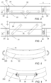
Figure 3 shows a schematic spanwise sectional view of the aircraft wing structure with the pop-up spoiler retracted; -
Figure 4 shows a schematic spanwise sectional view of the aircraft wing structure with the pop-up spoiler deployed; -
Figure 5 shows a schematic view of the wing structure under spanwise bending, showing the neutral plane; and -
Figure 6 shows the wing structure ofFigure 5 with the pin joint mounted pop-up spoiler unit on the neutral plane. -
Figure 1 shows anaircraft 10. Theaircraft 10 has afuselage 12, and starboard and port fixedwings engine 15 is mounted to eachwing aircraft 10 is a typical jet passenger transport aircraft but the invention is applicable to a wide variety of fixed wing aircraft types, including commercial, military, passenger, cargo, jet, propeller, general aviation, etc. with any number of engines attached to the wings or fuselage. - Each wing has a cantilevered wing structure with a length extending in a spanwise direction from a
root 18 to atip 19, with theroot 18 being joined to theaircraft fuselage 12. Thewings starboard wing 13 will be described in detail. Thewing 13 has a leadingedge 16 and atrailing edge 17. The leadingedge 16 is at the forward end of the wing and thetrailing edge 17 is at the rearward end of the wing. - The
wing 13 may comprise awing box 20. Thewing box 20 forms a structural assembly including forward and rear spars (part of the rear spar shown inFigure 2 ), ribs extending between the forward and rear spars. Thewing 13 may alternatively have a multi-spar construction. Regardless of the wing structure, the wing has upper and lower wing covers, 21, 22 and leading and trailing edge cover panels (collectively the "wing covers"), which form part of the outer aerodynamic surface of the wing. Thewing 13 has an upper aerodynamic surface between the leading andtrailing edges - The
wing 13 has a spanwise axis S which extends in a direction from thewing root 18 to thewing tip 19, and a chordwise axis which extends in the direction from the leadingedge 16 to thetrailing edge 17. Thewing 13 has an aerofoil cross section. Thewing 13 has a thickness direction perpendicular to the chordwise and spanwise directions. - The
wing 13 has a pop-up spoiler unit 30 as best shown inFigure 2 . The pop-up spoiler unit comprises anactuation mechanism 31 and aspoiler 32 coupled to the actuation mechanism. Thespoiler 32 is moved by theactuation mechanism 31 to translate along substantially a single linear axis without rotation. The spoiler is arranged to move substantially vertically in a direction substantially normal to the outer aerodynamic surface of the upper wing cover,e.g. wing cover 21. Thespoiler 32 is moveable by theactuation mechanism 31 to deploy through anaperture 23 in theupper wing cover 21. Alternatively, thespoiler 32 is moveable by theactuation mechanism 31 to deploy through an aperture in another of the wing covers, e.g. a leading edge cover panel or a trailing edge cover panel on the upper or lower surface of the wing. Thespoiler 32 is configured to move between a retracted position in which the spoiler is fully within the aerofoil profile of thewing 13, and an extended position in which the spoiler extends above the surface of theupper wing cover 21. Thespoiler 23 may have a plurality of extended positions. - The
spoiler 32 is arranged as a substantially flat wall or thick plate facing the oncoming airflow over the wing aerodynamic surface when the spoiler is in the extended position. Thespoiler 32 may have a length extending substantially in a spanwise direction of the wing, and a height extending substantially in a thickness direction of the wing. The length of thespoiler 32 may be several times its height. With thespoiler 32 facing the oncoming airflow, theactuation mechanism 31 may be behind the thick plate so as to be protected by the spoiler from high speed airflow. - The
aperture 23 in the wing cover may be an elongate slot, preferably a substantially rectangular slot. Thespoiler 32 may carry apanel 34. Thepanel 34 has an upper surface which forms a substantially flush surface with an outer aerodynamic surface of the upper wing cover,e.g. wing cover 21, when thespoiler 32 is in the retracted position. Thepanel 34 may be a substantially flat plate affixed to the top of thespoiler 32 to form a 'top hat'. Thepanel 34 moves with the deployment and retraction of thespoiler 32. Thepanel 34 may have a slightly curved surface to match the aerofoil profile of the wing 13 (i.e. the shape of the outer aerodynamic surface of the wing cover(s)) when thepanel 34 occupies theaperture 23.Figure 3 shows thespoiler 32 in the retracted position. - By activating the
actuation mechanism 31 to move the spoiler from the retracted position to the fully extended position, shown inFigure 4 , thespoiler 32 is moved through theaperture 23. Thepanel 34 atop thespoiler 32 lies substantially parallel with the outer aerodynamic surface of the upper wing cover,e.g. wing cover 21, so that in the extended position of the spoiler thepanel 34 is substantially aligned with the oncoming airflow over thewing 13. - The pop-up
spoiler unit 30 is mounted to theinternal wing structure 24 between the upper and lower aerodynamic surfaces of the wing. The pop-upspoiler unit 30 is mounted to theinternal wing structure 24 in such a way as to be substantially isolated from wing bending deflections. As shown inFigure 2 , thewing 13 has aneutral plane 25. Theneutral plane 25 of thewing 13 is the conceptual surface, shown as a surface bounded by a dot-dash broken line, through the cantilevered wing which is unstressed, either in tension or compression, as the cantilever wing bends. The neutral plane is not necessarily flat, it may be a curved conceptual surface. Theneutral plane 25 lies substantially midway between the upper and lower wing covers defining the upper and lower aerodynamic surfaces of the wing at a particular wing chord location. - The
neutral plane 25 is shown as a line in the cross section views ofFigures 3 and 4 through the wing. As can be seen the pop-upspoiler unit 30 is mounted to the wing structure at locations substantially lying in the neutral plane only. In this way, the pop-upspoiler 30 mountings are at locations that are not stressed, either in tension or compression, as thecantilever wing 13 bends. Therefore, as the wing bends, the spanwise spacing between the mounting locations of the pop-upspoiler unit 30 substantially does not change and so the wing bending loads, which cause extension and contraction away from the neutral plane in the spanwise direction during wing bending, are not transferred into the pop-upspoiler unit 30. - This is beneficial as the wing bending deflections and loads are therefore isolated from the pop-up
spoiler unit 30, so the pop-upspoiler unit 30 is not stressed and does not deform under the wing bending loads. This ensures that theactuation mechanism 31 of the pop-up spoiler unit is not subjected to stresses from the wing bending loads and so jamming of the actuation mechanism can be prevented. It is important that theactuation mechanism 31 is operable to move thespoiler 32 without jamming during wing bending deflections under all normal operating conditions of theaircraft wing 13, including when theaircraft 10 is in flight or is on the ground. Even small deflections of the pop-unit spoiler unit may be sufficient to cause the actuation mechanism to jam or at least lead to an unacceptable increase in load on an actuator of the actuation mechanism, and therefore need to be avoided. - The pop-up
spoiler unit 30 occupies substantially a full depth of the wing between upper and lower aerodynamic surfaces thereof, as shown inFigure 3 . Thespoiler 32 is substantially rigid to ensure that it does not significantly deflect under the high aerodynamic loads when in the extended position, even for a large transonic aircraft if deployed at cruise speeds, e.g. around Mach 0.8. - The pop-up
spoiler unit 30 is mounted to thewing structure 24 by pin joints 35 (also known as revolute joints) about which the pop-upspoiler 30 unit is substantially free to rotate. Each pin joint 35 includes a pin having a pin axis oriented substantially transverse to a spanwise axis S of the wing 13 (the pin axis is into the page inFigures 3 and 4 ). The pin axis lies substantially in the neutral plane and substantially normal to the local constant percentage chord line of the wing. The pop-upspoiler unit 30 is mounted to the wing structure at only twopin joints 35, each pin axis substantially lies in theneutral plane 25. Each pin joint 35 constrains relative motion of thewing structure 24 and the pop-upspoiler unit 30 to pure rotation along the pin axis. The pop-upspoiler unit 30 is mounted to thewing structure 24 by only two of the pin joints 35, one of the pin joints being located at each end of the pop-up spoiler unit in the spanwise direction S. -
Figure 5 shows schematically thewing 13 in an undeflected state 100 (no wing bending) in dotted broken line, and thewing 13 in a deflected state 200 (under wing bending) in solid line. In the deflected state with bending moment applied as shown by the arrows the upper wing cover,e.g. wing cover 21, is under compression and the lower wing cover,e.g. wing cover 22, is under tension. Theneutral plane 25 is again shown in dot dash broken line where the cantilevered wing which is unstressed, either in tension or compression, as the cantilever wing bends. -
Figure 6 shows thewing 13 in the deflectedstate 200 and with the pop-upspoiler 30 shown schematically and coupled to the wing structure by the pin joints 35 on theneutral plane 25 to illustrate how the pin joints 35 remain spaced apart by the same distance in the deflectedstate 200 as in theundeflected state 100, and the pin joints are unable to transfer bending moment from the wing structure into the pop-upspoiler unit 30, thereby isolating the pop-up spoiler unit from the wing bending deflections. - Where the word 'or' appears this is to be construed to mean 'and/or' such that items referred to are not necessarily mutually exclusive and may be used in any appropriate combination.
- Although the invention has been described above with reference to one or more preferred embodiments, it will be appreciated that various changes or modifications may be made without departing from the scope of the invention as defined in the appended claims.
Claims (15)
- An aircraft wing comprising a wing structure supporting a wing cover having an outer aerodynamic surface, and a pop-up spoiler unit including an actuation mechanism and a spoiler coupled to the actuation mechanism, wherein the spoiler is moveable by the actuation mechanism to deploy through an aperture in the wing cover, and wherein the pop-up spoiler unit is mounted to the wing structure so as to be substantially isolated from wing bending deflections.
- An aircraft wing according to claim 1, wherein the wing structure has a neutral plane, and wherein the pop-up spoiler unit is mounted to the wing structure at locations substantially lying in the neutral plane only.
- An aircraft wing according to claim 1 or claim 2, wherein the pop-up spoiler unit is mounted to the wing structure by pin joints about which the pop-up spoiler unit is substantially free to rotate.
- An aircraft wing according to claim 3, wherein each pin joint includes a pin having a pin axis oriented substantially transverse to a spanwise axis of the wing.
- An aircraft wing according to claim 4, wherein each pin joint constrains relative motion of the wing structure and the pop-up spoiler unit to pure rotation along the pin axis.
- An aircraft wing according to any of claims 3 to 5, wherein the pop-up spoiler unit is mounted to the wing structure by a pair of the pin joints, one of the pair of pin joints being located at each end of the pop-up spoiler unit.
- An aircraft wing according to any preceding claim, wherein the spoiler has a length extending substantially in a spanwise direction of the wing, and a height extending substantially in a thickness direction of the wing.
- An aircraft wing according to any preceding claim, wherein the spoiler is configured to deploy through an upper aerodynamic surface of the wing.
- An aircraft wing according to any preceding claim, wherein the aperture is an elongate slot.
- An aircraft wing according to any preceding claim, wherein the spoiler is arranged to move in a direction substantially normal to the outer aerodynamic surface of the wing cover.
- An aircraft wing according to any preceding claim, wherein the spoiler is moveable between a retracted and an extended position, and wherein the spoiler does not extend beyond an aerofoil profile of the wing when the spoiler is in the retracted position, preferably wherein the spoiler carries a panel, and the panel forms a substantially flush surface with the outer aerodynamic surface of the wing cover when the spoiler is in the retracted position.
- An aircraft wing according to any preceding claim, wherein the spoiler unit occupies substantially a full depth of the wing between upper and lower aerodynamic surfaces thereof.
- An aircraft wing according to any preceding claim, wherein the actuation mechanism is operable to move the spoiler without jamming during wing bending deflections under all normal operating conditions of the aircraft wing.
- An aircraft including the aircraft wing of any preceding claim, preferably wherein the actuation mechanism is operable to move the spoiler when the aircraft is in flight or is on the ground under all normal operating conditions of the aircraft, and preferably wherein the aircraft is a subsonic or transonic large transport aircraft.
- An aircraft wing comprising a wing structure supporting a wing cover having an outer aerodynamic surface, and a pop-up spoiler unit including an actuation mechanism and a spoiler coupled to the actuation mechanism, wherein the spoiler is moveable by the actuation mechanism to deploy through an aperture in the wing cover, wherein the wing structure has a neutral plane which is substantially neither stretched nor compressed during bending of the wing structure, and the pop-up spoiler unit is mounted to the wing structure at only two pin joints each having a respective pin axis about which the pop-up spoiler unit is substantially free to rotate, and each pin axis substantially lies in the neutral plane.
Applications Claiming Priority (1)
| Application Number | Priority Date | Filing Date | Title |
|---|---|---|---|
| GB2301109.1A GB2626560A (en) | 2023-01-26 | 2023-01-26 | Spoiler |
Publications (1)
| Publication Number | Publication Date |
|---|---|
| EP4406831A1 true EP4406831A1 (en) | 2024-07-31 |
Family
ID=85476421
Family Applications (1)
| Application Number | Title | Priority Date | Filing Date |
|---|---|---|---|
| EP24153238.1A Pending EP4406831A1 (en) | 2023-01-26 | 2024-01-22 | Spoiler |
Country Status (5)
| Country | Link |
|---|---|
| US (1) | US12365441B2 (en) |
| EP (1) | EP4406831A1 (en) |
| KR (1) | KR20240118022A (en) |
| CN (1) | CN118387285A (en) |
| GB (1) | GB2626560A (en) |
Citations (5)
| Publication number | Priority date | Publication date | Assignee | Title |
|---|---|---|---|---|
| DE733504C (en) * | 1936-07-17 | 1943-03-27 | Forschungsanstalt Fuer Segelfl | Spoiler flap |
| DE202015102982U1 (en) * | 2015-06-09 | 2015-06-24 | Waldemar Mezler | Tragfläche particular of an aircraft |
| CN109515689A (en) * | 2018-03-16 | 2019-03-26 | 陕西飞机工业(集团)有限公司 | A kind of aircraft trailing type spoiler differential control mechanism |
| US20190375493A1 (en) * | 2018-06-06 | 2019-12-12 | Ge Aviation Systems Limited | Method and apparatus for reducing aircraft wing bending moment |
| US20220144412A1 (en) * | 2020-11-09 | 2022-05-12 | Airbus Operations Limited | Aircraft spoiler and actuation apparatus |
Family Cites Families (17)
| Publication number | Priority date | Publication date | Assignee | Title |
|---|---|---|---|---|
| US1858259A (en) * | 1928-09-22 | 1932-05-17 | Alfaro Heraclio | Airplane |
| US2164531A (en) * | 1935-12-04 | 1939-07-04 | United Aircraft Corp | Control device for airplanes |
| US3064930A (en) | 1959-09-08 | 1962-11-20 | Nord Aviation | Roll control surfaces |
| US3318555A (en) * | 1966-04-21 | 1967-05-09 | North American Aviation Inc | Aircraft flight control system |
| US4693437A (en) * | 1984-10-11 | 1987-09-15 | Harry Khachikian | Spoileron control mechanism |
| US4783024A (en) * | 1986-11-17 | 1988-11-08 | Precise Flight, Inc. | Speedbrake |
| US6766981B2 (en) * | 2002-10-25 | 2004-07-27 | Northrop Grumman Corporation | Control system for alleviating a gust load on an aircraft wing |
| US7891612B2 (en) * | 2007-05-10 | 2011-02-22 | Amirhossein Mahmoudi | Flap device |
| GB0808349D0 (en) * | 2008-05-09 | 2008-06-18 | Airbus Uk Ltd | Spoiler deployment mechanism |
| US8740146B2 (en) * | 2008-06-12 | 2014-06-03 | Airbus Operations Gmbh | Cover panel for an aircraft, more particularly a landing gear cover panel for a cargo plane |
| FR2990744B1 (en) | 2012-05-16 | 2014-06-13 | Airbus Operations Sas | SUPPORT FOR CONDUIT FLOWING IN AN AIRCRAFT WING |
| CN104613061B (en) * | 2013-11-01 | 2018-09-04 | 空中客车简化股份公司 | Hold bent sub and aircraft |
| CN106240802A (en) | 2016-07-20 | 2016-12-21 | 天津津宇凯创航空科技发展有限公司 | A kind of wing aerodynamic deceleration mechanism |
| GB2590620A (en) * | 2019-12-20 | 2021-07-07 | Airbus Operations Ltd | Spoiler actuation apparatus for moving an aircraft spoiler |
| GB2600743A (en) * | 2020-11-09 | 2022-05-11 | Airbus Operations Ltd | Actuator and aircraft spoiler |
| GB2613342A (en) * | 2021-11-26 | 2023-06-07 | Airbus Operations Ltd | Aerodynamic control surface |
| GB2629364A (en) * | 2023-04-25 | 2024-10-30 | Airbus Operations Ltd | Pop-up spoiler |
-
2023
- 2023-01-26 GB GB2301109.1A patent/GB2626560A/en active Pending
-
2024
- 2024-01-22 EP EP24153238.1A patent/EP4406831A1/en active Pending
- 2024-01-23 KR KR1020240010351A patent/KR20240118022A/en active Pending
- 2024-01-24 CN CN202410102047.2A patent/CN118387285A/en active Pending
- 2024-01-25 US US18/422,761 patent/US12365441B2/en active Active
Patent Citations (5)
| Publication number | Priority date | Publication date | Assignee | Title |
|---|---|---|---|---|
| DE733504C (en) * | 1936-07-17 | 1943-03-27 | Forschungsanstalt Fuer Segelfl | Spoiler flap |
| DE202015102982U1 (en) * | 2015-06-09 | 2015-06-24 | Waldemar Mezler | Tragfläche particular of an aircraft |
| CN109515689A (en) * | 2018-03-16 | 2019-03-26 | 陕西飞机工业(集团)有限公司 | A kind of aircraft trailing type spoiler differential control mechanism |
| US20190375493A1 (en) * | 2018-06-06 | 2019-12-12 | Ge Aviation Systems Limited | Method and apparatus for reducing aircraft wing bending moment |
| US20220144412A1 (en) * | 2020-11-09 | 2022-05-12 | Airbus Operations Limited | Aircraft spoiler and actuation apparatus |
Also Published As
| Publication number | Publication date |
|---|---|
| GB202301109D0 (en) | 2023-03-15 |
| GB2626560A (en) | 2024-07-31 |
| US12365441B2 (en) | 2025-07-22 |
| KR20240118022A (en) | 2024-08-02 |
| US20240253772A1 (en) | 2024-08-01 |
| CN118387285A (en) | 2024-07-26 |
Similar Documents
| Publication | Publication Date | Title |
|---|---|---|
| EP2397403B1 (en) | Morphing control surface transition | |
| US7475848B2 (en) | Wing employing leading edge flaps and winglets to achieve improved aerodynamic performance | |
| USRE44313E1 (en) | Airplane with unswept slotted cruise wing airfoil | |
| EP2727826B1 (en) | Hinged raked wing tip | |
| US5294080A (en) | Lift enhancing tabs for airfoils | |
| US8622350B1 (en) | Compound leading edge device for aircraft | |
| WO1998017529A9 (en) | Airplane with unswept slotted cruise wing airfoil | |
| WO1994018069A1 (en) | High-efficiency, supersonic aircraft | |
| US5738298A (en) | Tip fence for reduction of lift-generated airframe noise | |
| US20050116116A1 (en) | Wing employing leading edge flaps and winglets to achieve improved aerodynamic performance | |
| US6935592B2 (en) | Aircraft lift device for low sonic boom | |
| US4093156A (en) | Supersonic transport | |
| EP4303121A1 (en) | Airfoil with flexible trailing edge | |
| US12365441B2 (en) | Spoiler | |
| US12187430B2 (en) | Underwing-mounted trailing edge bifold flaps for wings of aircraft | |
| US12269593B2 (en) | Wing assemblies and aircraft | |
| CN116176829A (en) | Aerodynamic control surface assembly | |
| US12377956B2 (en) | Aircraft assembly with moveable device and panel displaced from moveable device | |
| US12371151B2 (en) | Flight control surface | |
| EP4342789B1 (en) | Flight control surface | |
| US11214351B2 (en) | Wing, aircraft, and method for delaying wing stall of an aircraft | |
| GB2632284A (en) | Flight control surface deployment |
Legal Events
| Date | Code | Title | Description |
|---|---|---|---|
| PUAI | Public reference made under article 153(3) epc to a published international application that has entered the european phase |
Free format text: ORIGINAL CODE: 0009012 |
|
| STAA | Information on the status of an ep patent application or granted ep patent |
Free format text: STATUS: THE APPLICATION HAS BEEN PUBLISHED |
|
| AK | Designated contracting states |
Kind code of ref document: A1 Designated state(s): AL AT BE BG CH CY CZ DE DK EE ES FI FR GB GR HR HU IE IS IT LI LT LU LV MC ME MK MT NL NO PL PT RO RS SE SI SK SM TR |
|
| STAA | Information on the status of an ep patent application or granted ep patent |
Free format text: STATUS: REQUEST FOR EXAMINATION WAS MADE |
|
| 17P | Request for examination filed |
Effective date: 20250117 |
|
| GRAP | Despatch of communication of intention to grant a patent |
Free format text: ORIGINAL CODE: EPIDOSNIGR1 |
|
| STAA | Information on the status of an ep patent application or granted ep patent |
Free format text: STATUS: GRANT OF PATENT IS INTENDED |
|
| RIC1 | Information provided on ipc code assigned before grant |
Ipc: B64C 9/02 20060101AFI20251222BHEP Ipc: B64C 9/14 20060101ALI20251222BHEP Ipc: B64C 9/32 20060101ALI20251222BHEP Ipc: B64C 13/28 20060101ALI20251222BHEP |
|
| INTG | Intention to grant announced |
Effective date: 20260123 |
|
| GRAS | Grant fee paid |
Free format text: ORIGINAL CODE: EPIDOSNIGR3 |
|
| GRAA | (expected) grant |
Free format text: ORIGINAL CODE: 0009210 |
|
| STAA | Information on the status of an ep patent application or granted ep patent |
Free format text: STATUS: THE PATENT HAS BEEN GRANTED |